Multiresolution Modelling of Polygonal Surface Meshes Using Triangle Fans Jos´ e Ribelles, Angeles L´ opez, Inmaculada Remolar, Oscar Belmonte, and Miguel Chover Departamento de Inform´ atica, Universitat Jaume I, E-12080 Castell´ on, Spain {ribelles,lopeza,remolar,belfern,chover}@uji.es Abstract. Multiresolution modelling of polygonal surface meshes has been presented as a solution for the interactive visualisation of scenes formed by hundreds of thousands of polygons. On the other hand, it has been shown that representing surfaces using sets of triangle strips or fans greatly reduces visualisation time and provides an important memory savings. In this paper we present a new method to model polygonal surface meshes. Like the previously explained Multiresolution Ordered Meshes (MOM), this method permits the efficient management of an ample range of approximations of the given model. Furthermore, this method utilises the triangle fan as its basic representation primitive. Experiments realised with data sets of varying complexity demonstrate reduced storage space requirements, while retaining the advantages of MOMs. 1 Introduction One of the principle objectives of multiresolution modelling [1] is to permit in- teractive visualisation of surfaces formed by thousands of polygons. Given a mesh, M , a multiresolution model defines how to store and retrieve n differ- ent approximations or levels of detail (LOD), M 0 ,M 1 , ....,M n−1 , in an efficient manner. Several mechanisms have been developed to accelerate the process of visual- ising polygonal models. For example, strips and fans of triangles (see figure 1) appear as drawing primitives in some graphics libraries, such as OpenGL. This type of primitives allow for rapid visualisation. To draw a fan of n triangles, for example, it is only necessary to pass n+2 vertices, instead of 3n, to the graphics processor. This not only reduces computation time due to a reduction in vertices, but also an important memory savings. Obtaining the optimal set of strips or fans for a given surface is a process realised off-line when working with static models. However, when working with a multiresolution model, the surface connectivity changes with changes in level Supportedby grant TIC1999-0510-C02-02 (CICYT, Ministerio de Educaci´on y Cien- cia) G. Borgefors, I. Nystr¨om, and G. Sanniti di Baja (Eds.): DGCI 2000, LNCS 1953, pp. 431–443, 2000. c Springer-Verlag Berlin Heidelberg 2000
Transcript
Multiresolution Modelling of Polygonal Surface
Meshes Using Triangle Fans�
Jose Ribelles, Angeles Lopez, Inmaculada Remolar,Oscar Belmonte, and Miguel Chover
Departamento de Informatica, Universitat Jaume I,E-12080 Castellon, Spain
{ribelles,lopeza,remolar,belfern,chover}@uji.es
Abstract. Multiresolution modelling of polygonal surface meshes hasbeen presented as a solution for the interactive visualisation of scenesformed by hundreds of thousands of polygons. On the other hand, it hasbeen shown that representing surfaces using sets of triangle strips or fansgreatly reduces visualisation time and provides an important memorysavings. In this paper we present a new method to model polygonalsurface meshes. Like the previously explained Multiresolution OrderedMeshes (MOM), this method permits the efficient management of anample range of approximations of the given model. Furthermore, thismethod utilises the triangle fan as its basic representation primitive.Experiments realised with data sets of varying complexity demonstratereduced storage space requirements, while retaining the advantages ofMOMs.
1 Introduction
One of the principle objectives of multiresolution modelling [1] is to permit in-teractive visualisation of surfaces formed by thousands of polygons. Given amesh, M , a multiresolution model defines how to store and retrieve n differ-ent approximations or levels of detail (LOD), M0, M1, ...., Mn−1, in an efficientmanner.
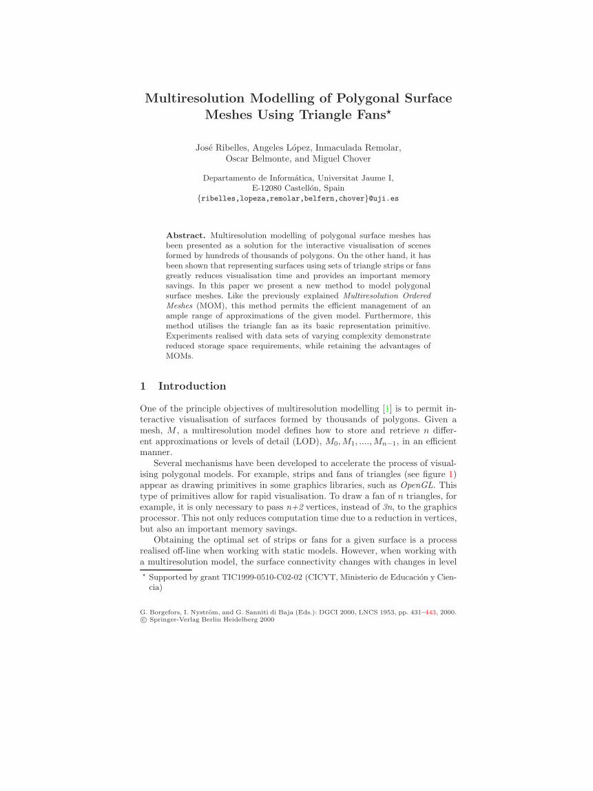
Several mechanisms have been developed to accelerate the process of visual-ising polygonal models. For example, strips and fans of triangles (see figure 1)appear as drawing primitives in some graphics libraries, such as OpenGL. Thistype of primitives allow for rapid visualisation. To draw a fan of n triangles, forexample, it is only necessary to pass n+2 vertices, instead of 3n, to the graphicsprocessor. This not only reduces computation time due to a reduction in vertices,but also an important memory savings.
Obtaining the optimal set of strips or fans for a given surface is a processrealised off-line when working with static models. However, when working witha multiresolution model, the surface connectivity changes with changes in level� Supported by grant TIC1999-0510-C02-02 (CICYT, Ministerio de Educacion y Cien-cia)
Fig. 1. Example of a strip and a fan of triangles. On the left, a strip defined byv0, v1, v2, v3, v4, v5 and on the right, a fan defined by v0, v1, v2, v3, v4, v5, v6, v1
Model Mesh LOD
UpdateMultiresolution
Triangle Strips LOD
DisplayGenerate
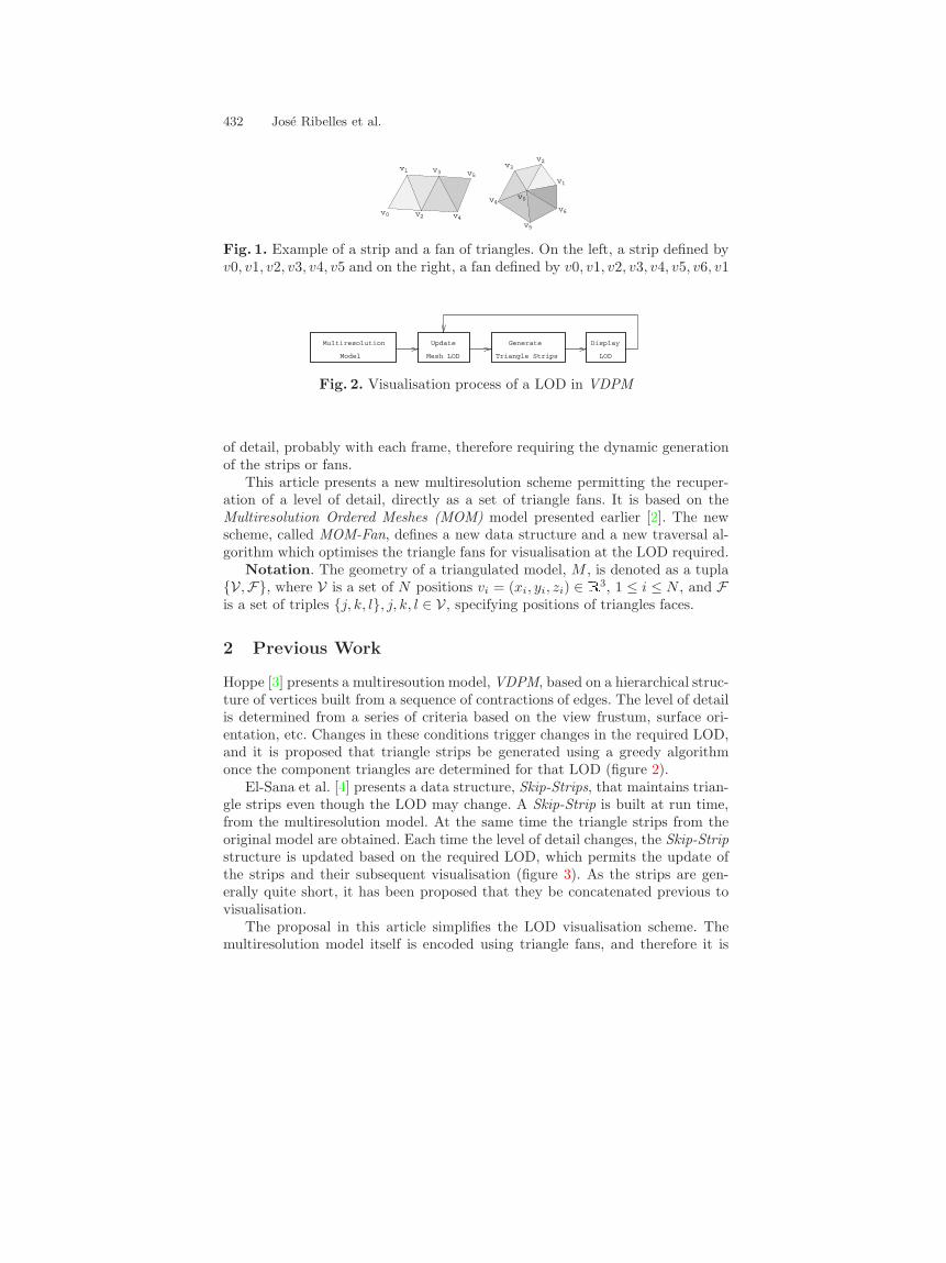
Fig. 2. Visualisation process of a LOD in VDPM
of detail, probably with each frame, therefore requiring the dynamic generationof the strips or fans.
This article presents a new multiresolution scheme permitting the recuper-ation of a level of detail, directly as a set of triangle fans. It is based on theMultiresolution Ordered Meshes (MOM) model presented earlier [2]. The newscheme, called MOM-Fan, defines a new data structure and a new traversal al-gorithm which optimises the triangle fans for visualisation at the LOD required.
Notation. The geometry of a triangulated model, M , is denoted as a tupla{V ,F}, where V is a set of N positions vi = (xi, yi, zi) ∈ R3, 1 ≤ i ≤ N , and Fis a set of triples {j, k, l}, j, k, l ∈ V , specifying positions of triangles faces.
2 Previous Work
Hoppe [3] presents a multiresoution model, VDPM, based on a hierarchical struc-ture of vertices built from a sequence of contractions of edges. The level of detailis determined from a series of criteria based on the view frustum, surface ori-entation, etc. Changes in these conditions trigger changes in the required LOD,and it is proposed that triangle strips be generated using a greedy algorithmonce the component triangles are determined for that LOD (figure 2).
El-Sana et al. [4] presents a data structure, Skip-Strips, that maintains trian-gle strips even though the LOD may change. A Skip-Strip is built at run time,from the multiresolution model. At the same time the triangle strips from theoriginal model are obtained. Each time the level of detail changes, the Skip-Stripstructure is updated based on the required LOD, which permits the update ofthe strips and their subsequent visualisation (figure 3). As the strips are gen-erally quite short, it has been proposed that they be concatenated previous tovisualisation.
The proposal in this article simplifies the LOD visualisation scheme. Themultiresolution model itself is encoded using triangle fans, and therefore it is
Multiresolution Modelling Using Triangle Fans 433
Skip-Strips Strips
JoinBuild
Generate Triangle Strips
Model
Multiresolution
Mesh LOD
Update Update
Skip-Strips Strips
Update Display
LOD
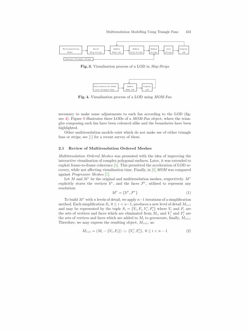
Fig. 3. Visualisation process of a LOD in Skip-Strips
Mesh LOD
Update Display
LOD
Multiresolution Model
with Triangle Fans
Fig. 4. Visualisation process of a LOD using MOM-Fan
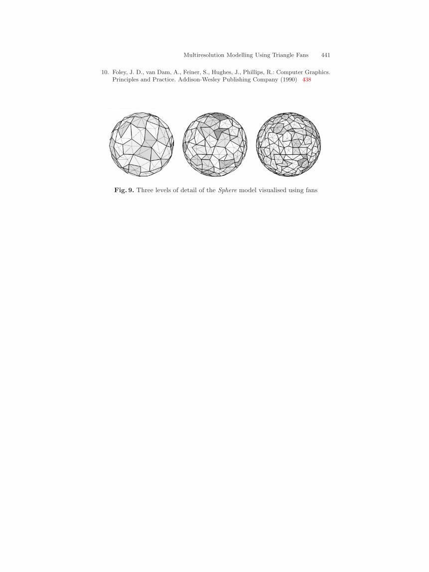
necessary to make some adjustments to each fan according to the LOD (fig-ure 4). Figure 9 illustrates three LODs of a MOM-Fan object, where the trian-gles composing each fan have been coloured alike and the boundaries have beenhighlighted.
Other multiresolution models exist which do not make use of either trianglefans or strips; see [1] for a recent survey of these.
2.1 Review of Multiresolution Ordered Meshes
Multitresolution Ordered Meshes was presented with the idea of improving theinteractive visualisation of complex polygonal surfaces. Later, it was extended toexploit frame-to-frame coherence [5]. This permitted the acceleration of LOD re-covery, while not affecting visualisation time. Finally, in [6] MOM was comparedagainst Progressive Meshes [7].
Let M and M r be the original and multiresolution meshes, respectively. M r
explicitly stores the vertices Vr, and the faces Fr, utilised to represent anyresolution:
M r = {Vr,Fr} (1)
To build M r with n levels of detail, we apply n−1 iterations of a simplificationmethod. Each simplification Si, 0 ≤ i < n−1, produces a new level of detail Mi+1
and may be represented by the tuple Si = {Vi, Fi, V′i , F ′
i} where Vi and Fi arethe sets of vertices and faces which are eliminated from Mi, and V ′
i and F ′i are
the sets of vertices and faces which are added to Mi to gerenerate, finally, Mi+1.Therefore, we may express the resulting object, Mi+1, as:
Mi+1 = (Mi − {Vi, Fi}) ∪ {V ′i , F ′
i}, 0 ≤ i < n − 1 (2)
434 Jose Ribelles et al.
Given that M r stores all vertices and faces that can be used at any set level ofdetail, M r can be defined as:
M r =n−1⋃
i=0
Mi, n ≥ 1 (3)
From the equations 1 - 3, we derive that M r can be expressed as the initialmesh, M = M0, plus all vertices and faces generated in each iteration of thesimplification process:
Vr = V0 ∪ V ′0 ∪ V ′
1 ∪ ... ∪ V ′n−2 = V0 ∪
n−2⋃
i=0
V ′i (4)
Fr = F0 ∪ F ′0 ∪ F ′
1 ∪ ... ∪ F ′n−2 = F0 ∪
n−2⋃
i=0
F ′i (5)
or also, as the mesh corresponding to the worst level of detail, Mn−1, plus thevertices and faces eliminated in each iteration of the simplification process:
Vr = V0 ∪ V1 ∪ ... ∪ Vn−2 ∪ Vn−1 =n−2⋃
i=0
Vi ∪ Vn−1 (6)
Fr = F0 ∪ F1 ∪ ... ∪ Fn−2 ∪ Fn−1 =n−2⋃
i=0
Fi ∪ Fn−1 (7)
The basic idea of MOM is based on the expressions of the two previousequations. That is, store in ordered form the sequences of vertices and faceseliminated, Vi and Fi, 0 ≤ i < n − 2, plus the vertices and faces correspondingto the worst level of detail Mn−1 = {Vn−1,Fn−1}. Each stored face is identifiedby a value representing its position in the face sequence ordered according toequation 5 above. MOM-Fan is based on the same idea, the difference beingthat here we store and manipulate triangle fans instead of isolated triangles. Insection 3 we show how to store the fans in the data structure, and in section 4how to recover those fans which form a given level of detail.
3 Data Structure
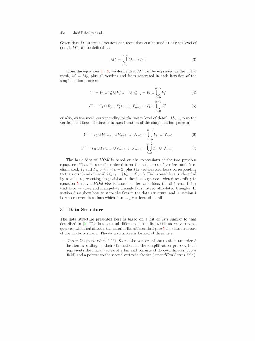
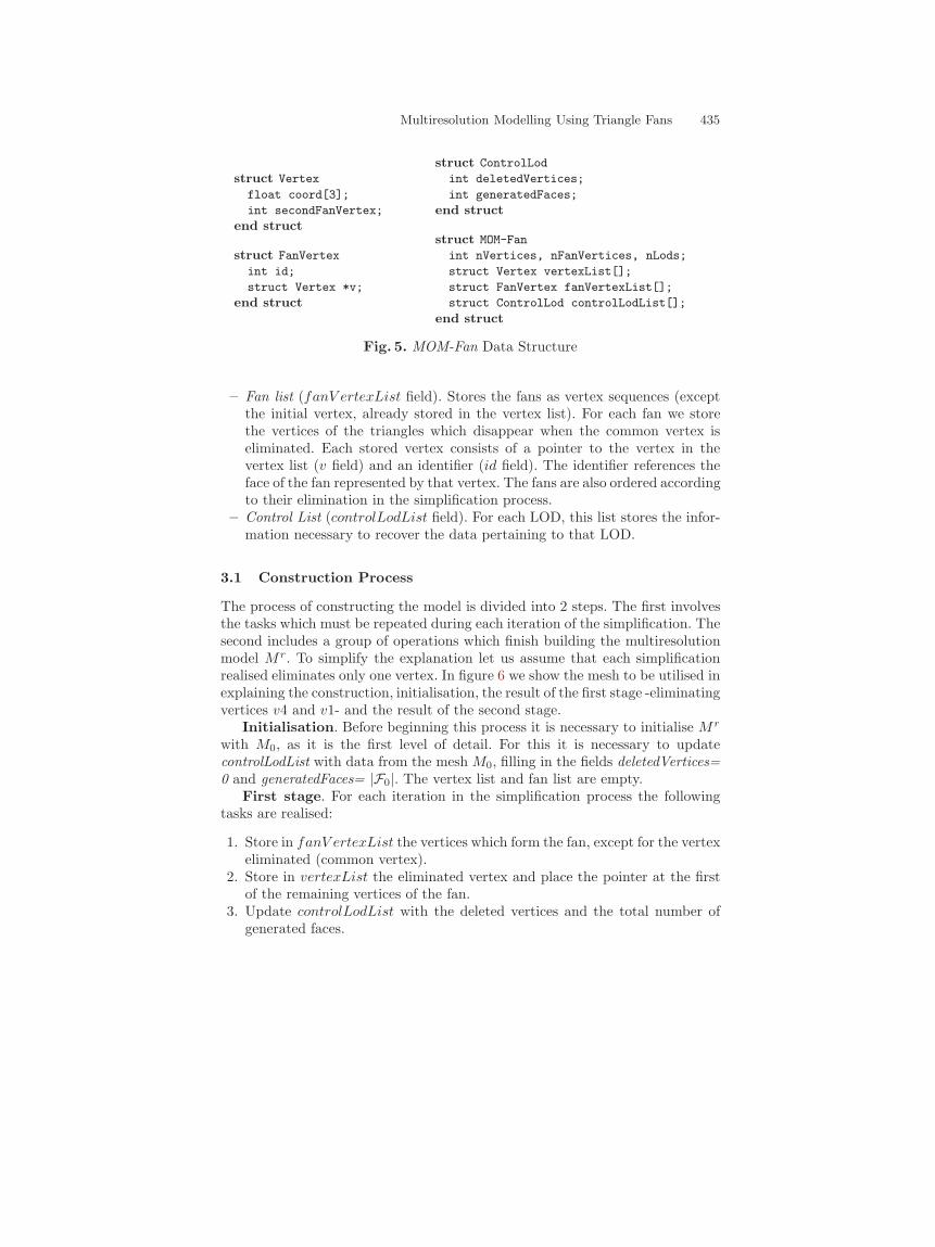
The data structure presented here is based on a list of lists similar to thatdescribed in [2]. The fundamental difference is the list which stores vertex se-quences, which substitutes the anterior list of faces. In figure 5 the data structureof the model is shown. The data structure is formed of three lists:
– Vertex list (vertexList field). Stores the vertices of the mesh in an orderedfashion according to their elimination in the simplification process. Eachrepresents the initial vertex of a fan and consists of its co-ordinates (coordfield) and a pointer to the second vertex in the fan (secondFanV ertex field).
Multiresolution Modelling Using Triangle Fans 435
struct Vertex
float coord[3];
int secondFanVertex;
end struct
struct FanVertex
int id;
struct Vertex *v;
end struct
struct ControlLod
int deletedVertices;
int generatedFaces;
end struct
struct MOM-Fan
int nVertices, nFanVertices, nLods;
struct Vertex vertexList[];
struct FanVertex fanVertexList[];
struct ControlLod controlLodList[];
end struct
Fig. 5. MOM-Fan Data Structure
– Fan list (fanV ertexList field). Stores the fans as vertex sequences (exceptthe initial vertex, already stored in the vertex list). For each fan we storethe vertices of the triangles which disappear when the common vertex iseliminated. Each stored vertex consists of a pointer to the vertex in thevertex list (v field) and an identifier (id field). The identifier references theface of the fan represented by that vertex. The fans are also ordered accordingto their elimination in the simplification process.
– Control List (controlLodList field). For each LOD, this list stores the infor-mation necessary to recover the data pertaining to that LOD.
3.1 Construction Process
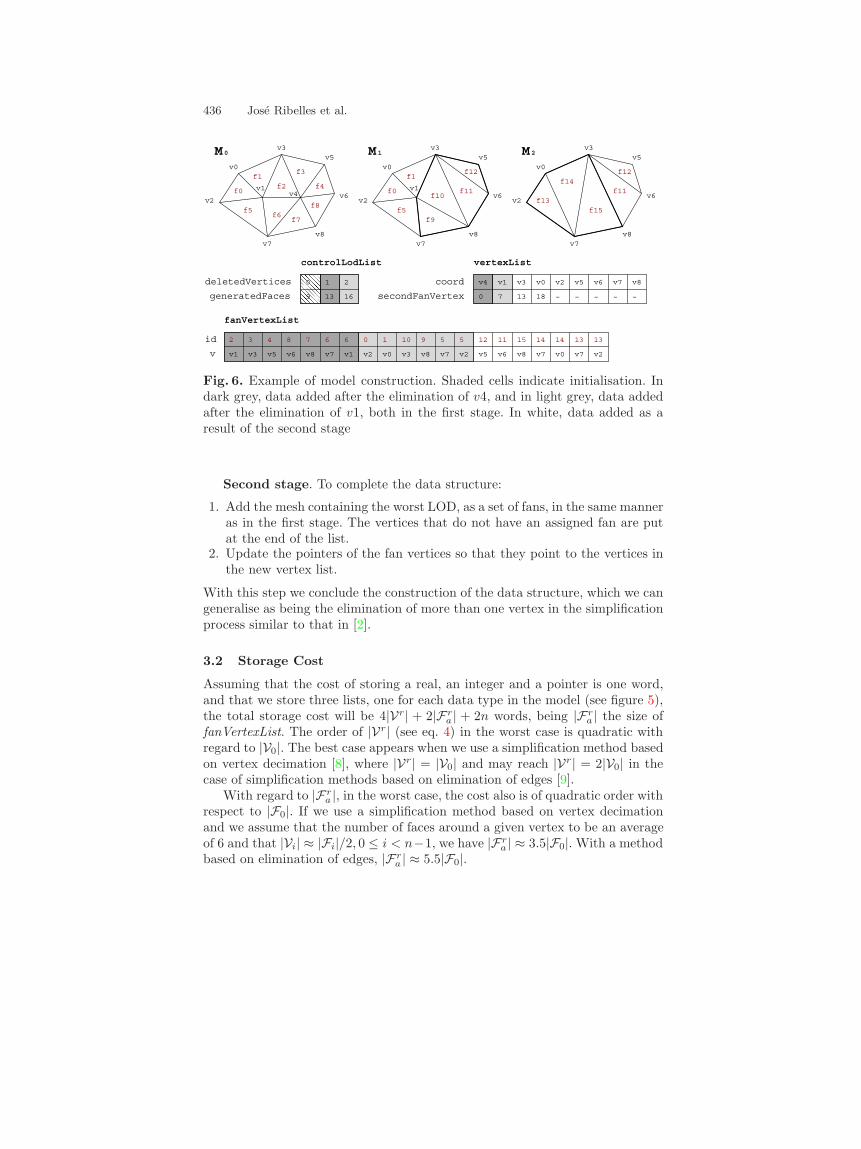
The process of constructing the model is divided into 2 steps. The first involvesthe tasks which must be repeated during each iteration of the simplification. Thesecond includes a group of operations which finish building the multiresolutionmodel M r. To simplify the explanation let us assume that each simplificationrealised eliminates only one vertex. In figure 6 we show the mesh to be utilised inexplaining the construction, initialisation, the result of the first stage -eliminatingvertices v4 and v1- and the result of the second stage.
Initialisation. Before beginning this process it is necessary to initialise M r
with M0, as it is the first level of detail. For this it is necessary to updatecontrolLodList with data from the mesh M0, filling in the fields deletedVertices=0 and generatedFaces= |F0|. The vertex list and fan list are empty.
First stage. For each iteration in the simplification process the followingtasks are realised:
1. Store in fanV ertexList the vertices which form the fan, except for the vertexeliminated (common vertex).
2. Store in vertexList the eliminated vertex and place the pointer at the firstof the remaining vertices of the fan.
3. Update controlLodList with the deleted vertices and the total number ofgenerated faces.
436 Jose Ribelles et al.
��������9
0 1 2
13 16
v1 v3 v5 v7
2
v1 v2 v8
3 4 8 7 6 6 0 1 10 9
v6 v8 v0 v3
5 5 12 11 15
v7 v2 v5 v6 v8 v7 v0 v7 v2
14 14 13 13
v1v4
0 7
v3 v0 v2
13 18 ~
v5 v6 v7 v8
~ ~ ~ ~
v5v3
v6
v8v7
v2
v0f1
f5
f0 v1
f6
f2
f7
f3
f4
f8
v4
v5
f12
v3
v6
v8v7
v2
v0
f11f10
f1
f5f9
f0 v1
M1 M2v5
f12
v3
v6
v8v7
v2
v0
f13
f14
f15
f11
deletedVertices
generatedFaces
controlLodList
id
v
fanVertexList
vertexList
coord
secondFanVertex
M0
Fig. 6. Example of model construction. Shaded cells indicate initialisation. Indark grey, data added after the elimination of v4, and in light grey, data addedafter the elimination of v1, both in the first stage. In white, data added as aresult of the second stage
Second stage. To complete the data structure:
1. Add the mesh containing the worst LOD, as a set of fans, in the same manneras in the first stage. The vertices that do not have an assigned fan are putat the end of the list.
2. Update the pointers of the fan vertices so that they point to the vertices inthe new vertex list.
With this step we conclude the construction of the data structure, which we cangeneralise as being the elimination of more than one vertex in the simplificationprocess similar to that in [2].
3.2 Storage Cost
Assuming that the cost of storing a real, an integer and a pointer is one word,and that we store three lists, one for each data type in the model (see figure 5),the total storage cost will be 4|Vr| + 2|Fr
a | + 2n words, being |Fra | the size of
fanVertexList. The order of |Vr| (see eq. 4) in the worst case is quadratic withregard to |V0|. The best case appears when we use a simplification method basedon vertex decimation [8], where |Vr| = |V0| and may reach |Vr| = 2|V0| in thecase of simplification methods based on elimination of edges [9].
With regard to |Fra |, in the worst case, the cost also is of quadratic order with
respect to |F0|. If we use a simplification method based on vertex decimationand we assume that the number of faces around a given vertex to be an averageof 6 and that |Vi| ≈ |Fi|/2, 0 ≤ i < n−1, we have |Fr
a | ≈ 3.5|F0|. With a methodbased on elimination of edges, |Fr
a | ≈ 5.5|F0|.
Multiresolution Modelling Using Triangle Fans 437
for each vertex v from DV and while there exist triangles to paintInterruptionFan <- true {force the a.1 case}for each vertex vi of the fan associated with v, from the first to the penultimate
if fanVertexList[vi].id < GF then {case a) paint vi}if InterruptionFan thenpaint(v) {case a.1) paint the initial vertex}InterruptionFan <- false {do not repeat case a.1)}
end ifpaint(vi)
NF <- NF-1
else {case b) do not visualise vi}if no InterruptionFan thenpaint(vi) {paint vi to close triangle}InterruptionFan <- true {force case a.1)}
end ifend if
end forif no InterruptionFan then
paint(vi) {last vertex vi from the list, to close fan}end if
end for
Fig. 7. Visualisation algorithm
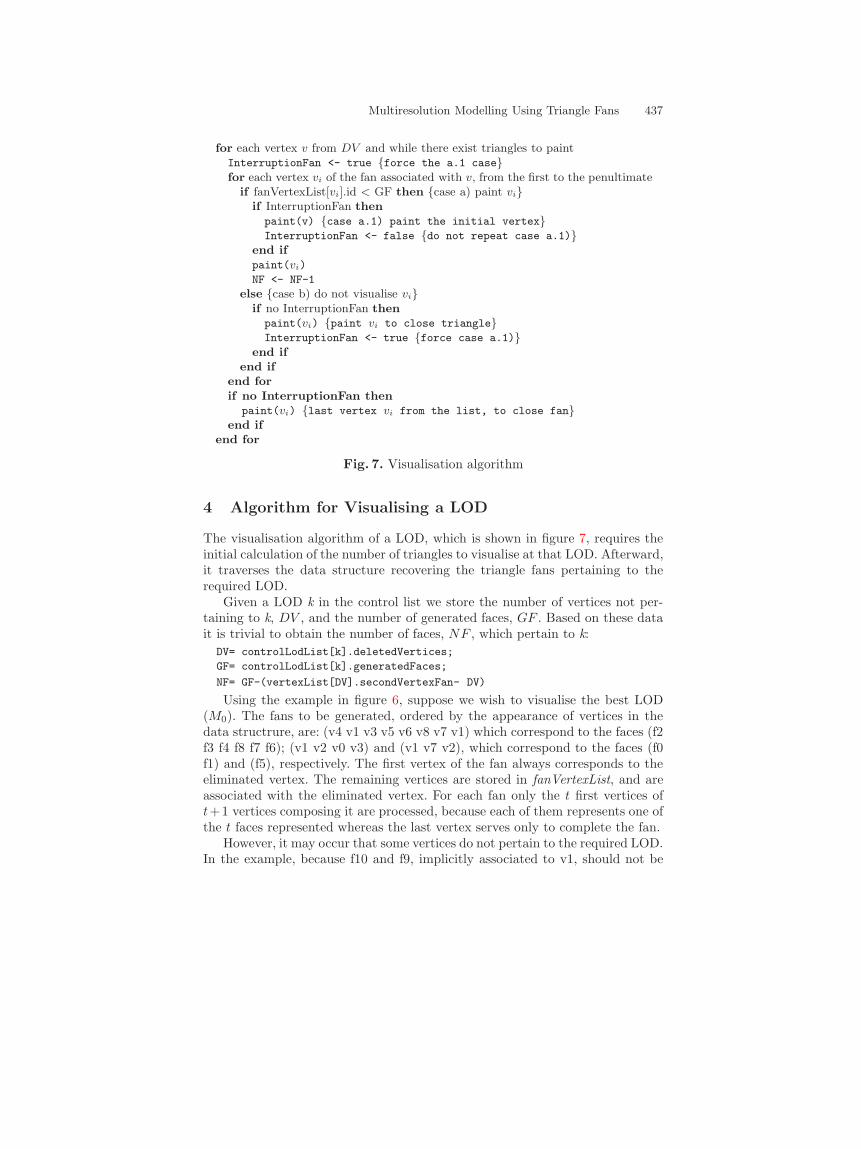
4 Algorithm for Visualising a LOD
The visualisation algorithm of a LOD, which is shown in figure 7, requires theinitial calculation of the number of triangles to visualise at that LOD. Afterward,it traverses the data structure recovering the triangle fans pertaining to therequired LOD.
Given a LOD k in the control list we store the number of vertices not per-taining to k, DV , and the number of generated faces, GF . Based on these datait is trivial to obtain the number of faces, NF , which pertain to k:
DV= controlLodList[k].deletedVertices;
GF= controlLodList[k].generatedFaces;
NF= GF-(vertexList[DV].secondVertexFan- DV)
Using the example in figure 6, suppose we wish to visualise the best LOD(M0). The fans to be generated, ordered by the appearance of vertices in thedata structrure, are: (v4 v1 v3 v5 v6 v8 v7 v1) which correspond to the faces (f2f3 f4 f8 f7 f6); (v1 v2 v0 v3) and (v1 v7 v2), which correspond to the faces (f0f1) and (f5), respectively. The first vertex of the fan always corresponds to theeliminated vertex. The remaining vertices are stored in fanVertexList, and areassociated with the eliminated vertex. For each fan only the t first vertices oft+1 vertices composing it are processed, because each of them represents one ofthe t faces represented whereas the last vertex serves only to complete the fan.
However, it may occur that some vertices do not pertain to the required LOD.In the example, because f10 and f9, implicitly associated to v1, should not be
438 Jose Ribelles et al.
visualised, there is a jump from vertex v3 to v7. To resolve these jumps withoutsplitting fans, it is necessary to introduce the vertex v1 between v3 and v7,thus producing two degenerate triangles. While the first fan is resolved withoutdegenerate triangles (v4 v1 v3 v5 v6 v8 v7 v1), the second fan (v1 v2 v0 v3 v1 v7v2) includes two of them, (v1 v3 v1) and (v1 v1 v7). Upon processing each of thevertices two things may occur: a) the vertex identifier indicates that the triangleshould be painted, or b) the vertex identifier indicates that the triangle shouldnot be painted. When the second case occurs, this signifies an interruption inthe fan, and if this continues further along it is necessary to insert the initialvertex. Therefore, the first time that case a) is encountered after an interruptionthe insertion should be realised (case a.1 in the algorithm).
The computational cost of the algorithm to extract LOD k depends on thetotal number of vertices not eliminated, which is at most |Vr| − k, and the totalnumber of vertices of the associated fans, which is at most |Fr
a | − 2k. |Vr| and|Fr
a | are, in the worst case, of quadratic order with respect to |V0| and |F0|,respectively, but this case differs substantially from the normal case. With themethod of simplification by elimination of vertices the cost is O(8|Vk|) and witha method based on edge elimination, O(13|Vk|).
5 Results
The experiments were realised utilising a Silicon Graphics RealityEngine 2, witha MIPS R10000 at 194 MHz and 256 Mb RAM. Coding of the model was in C++and utilised OpenGL as its graphics library. The simplification method used toconstruct the multiresolution representations is that proposed by Garland andHeckbert [9] based on contraction of edges. The meshes come from the StanfordUniversity Computer Graphics Laboratory (http://www-graphics.stanford.edu/data/3Dscanrep/) and Cyberware (http://www.cyberware.com/models/).
In table 1 we summarise the characteristics and storage costs of the objectsused in the experiments. For each of them we indicate the number of verticesand faces of the original model, and its storage cost assuming a structure basedon a vertex list and a triangle list [10]. Also it is assumed that a word (integer,real, or pointer) carries a set cost of 4 bytes. With regard to the multiresolutionordered mesh (MOM) representation, we indicate the number of levels of detail,the number of faces and the total storage cost. Regarding the new representa-tion proposed in this article, we indicate the number of fanVertex and the totalstorage cost. It can be observed that the number of fan vertices stored in thenew representation is higher than that of the faces in the MOM representation.However, given that the cost to store a fan vertex is less than for a face, thestorage cost of the new list provides a memory savings of about 20% over theface list. The repercussion of this is that the total storage cost is reduced byan important amount, approximately 15%, due to the fact that the list which isreduced is the ”heaviest” list in the model (compare the number of faces withthe number of vertices and LODs).
Multiresolution Modelling Using Triangle Fans 439
Table 1. Characteristics and storage costs
Original MOM MOM-FanVertices Faces MB Lods Faces MB Fan V. MB
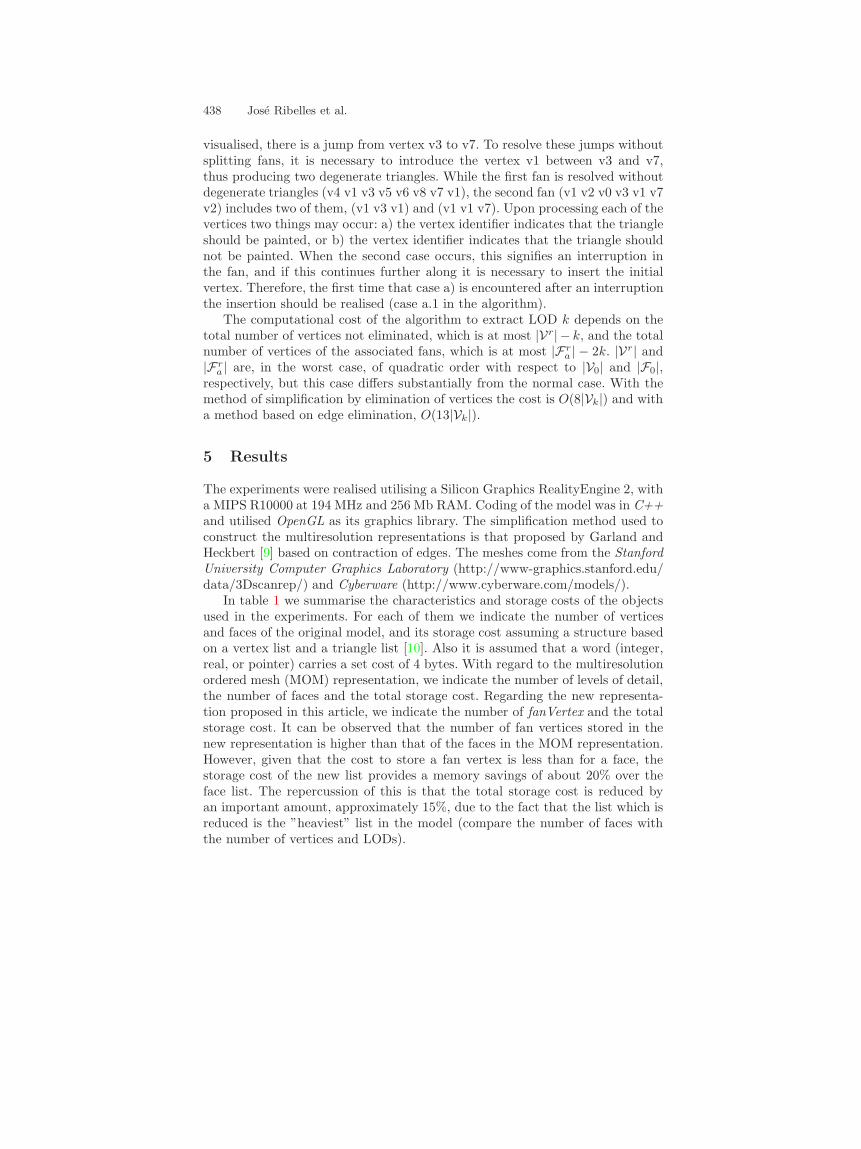
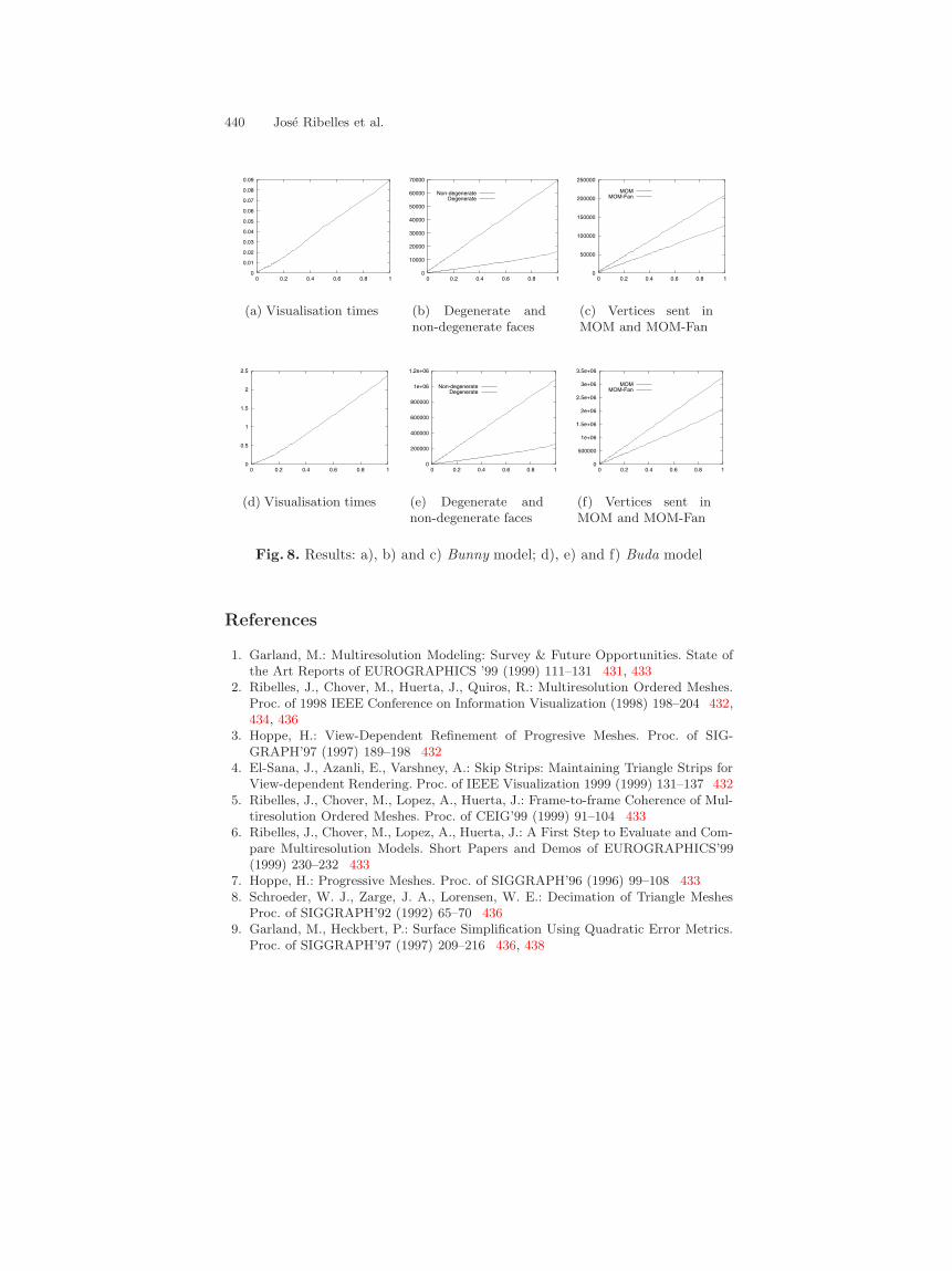
In figures 8(a) and 8(d) the behavior of the new representation is shown,using the Bunny and Buda models (some views of them are shown in figures 10and 11). On the X-axis the level of detail is represented, where 0 is the poorestand 1 the best. On the Y-axis we show the time spent (in seconds) for themodel to recover the data pertaining to a given LOD and to visualise them. Thebehavior is similar to that obtained with the earlier MOM scheme and one canobserve the linear response with respect to the number of triangles of the LODvisualised. The improvement gained by the use of triangle fans is diminishedsomewhat by the slight increase in data recovery time due to a more complexalgorithm, the short length of fans (an average of 3.3 triangles per fan), thedegenerate triangles, and the overhead caused by executing, for each fan, theinstructions glBegin and glEnd in the OpenGL implementation. In figures 8(b)and 8(e) we show the number of non-degenerate triangles and the number ofdegenerates (around 23% of the total triangles) sent to the graphic subsystemper LOD. In figure 8(c) and 8(f) we show the number of vertices sent per LODin the MOM representation, and those sent in the new representation (about40% fewer).
6 Conclusions and Future Work
In this article we present a new multiresolution scheme which permits the storageand visualisation of the distinct levels of detail as triangle fans. The objective isdouble: to reduce the visualisation time and also the space (storage) cost.
The experimental results show a reduction of about 15% in storage cost withrespect to the previous MOM representation, upon which the new approximationis based. However, the behavior of the new model regarding its visualisationtime, is similar to its ancestor. A short average fan length, the high percentageof degenerate triangles, and the necessity to adjust the fans to the required LODin real-time contribute to produce overall results which do not suppose a globalimprovement in visualisation time.
This work will proceed from this moment on, toward the utilisation of trianglestrips which, in principle, will permit a higher average number of triangles perstrip than has been obtained using fans. In this manner we expect the storagecost to be further improved, as well as visualisation times.
440 Jose Ribelles et al.
0
0.01
0.02
0.03
0.04
0.05
0.06
0.07
0.08
0.09
0 0.2 0.4 0.6 0.8 1
(a) Visualisation times
0
10000
20000
30000
40000
50000
60000
70000
0 0.2 0.4 0.6 0.8 1
Non-degenerateDegenerate
(b) Degenerate andnon-degenerate faces
0
50000
100000
150000
200000
250000
0 0.2 0.4 0.6 0.8 1
MOMMOM-Fan
(c) Vertices sent inMOM and MOM-Fan
0
0.5
1
1.5
2
2.5
0 0.2 0.4 0.6 0.8 1
(d) Visualisation times
0
200000
400000
600000
800000
1e+06
1.2e+06
0 0.2 0.4 0.6 0.8 1
Non-degenerateDegenerate
(e) Degenerate andnon-degenerate faces
0
500000
1e+06
1.5e+06
2e+06
2.5e+06
3e+06
3.5e+06
0 0.2 0.4 0.6 0.8 1
MOMMOM-Fan
(f) Vertices sent inMOM and MOM-Fan
Fig. 8. Results: a), b) and c) Bunny model; d), e) and f) Buda model
References
1. Garland, M.: Multiresolution Modeling: Survey & Future Opportunities. State ofthe Art Reports of EUROGRAPHICS ’99 (1999) 111–131 431, 433
2. Ribelles, J., Chover, M., Huerta, J., Quiros, R.: Multiresolution Ordered Meshes.Proc. of 1998 IEEE Conference on Information Visualization (1998) 198–204 432,434, 436
3. Hoppe, H.: View-Dependent Refinement of Progresive Meshes. Proc. of SIG-GRAPH’97 (1997) 189–198 432
4. El-Sana, J., Azanli, E., Varshney, A.: Skip Strips: Maintaining Triangle Strips forView-dependent Rendering. Proc. of IEEE Visualization 1999 (1999) 131–137 432
5. Ribelles, J., Chover, M., Lopez, A., Huerta, J.: Frame-to-frame Coherence of Mul-tiresolution Ordered Meshes. Proc. of CEIG’99 (1999) 91–104 433
6. Ribelles, J., Chover, M., Lopez, A., Huerta, J.: A First Step to Evaluate and Com-pare Multiresolution Models. Short Papers and Demos of EUROGRAPHICS’99(1999) 230–232 433
7. Hoppe, H.: Progressive Meshes. Proc. of SIGGRAPH’96 (1996) 99–108 4338. Schroeder, W. J., Zarge, J. A., Lorensen, W. E.: Decimation of Triangle Meshes
Proc. of SIGGRAPH’92 (1992) 65–70 4369. Garland, M., Heckbert, P.: Surface Simplification Using Quadratic Error Metrics.
Proc. of SIGGRAPH’97 (1997) 209–216 436, 438
Multiresolution Modelling Using Triangle Fans 441
10. Foley, J. D., van Dam, A., Feiner, S., Hughes, J., Phillips, R.: Computer Graphics.Principles and Practice. Addison-Wesley Publishing Company (1990) 438
Fig. 9. Three levels of detail of the Sphere model visualised using fans
442 Jose Ribelles et al.
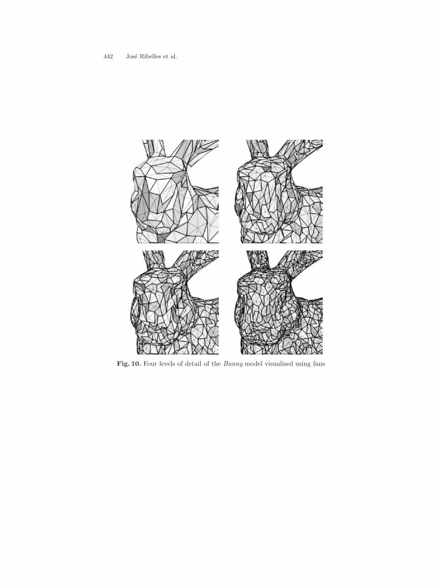
Fig. 10. Four levels of detail of the Bunny model visualised using fans
Multiresolution Modelling Using Triangle Fans 443
Fig. 11. Two levels of detail of the Buda model visualised using fans