Old Dominion University ODU Digital Commons Computer Science Faculty Publications Computer Science 2011 Multitissue Tetrahedral Image-to-Mesh Conversion with Guaranteed Quality and Fidelity Andrey N. Chernikov Old Dominion University Nikos P. Chrisochoides Old Dominion University Follow this and additional works at: hps://digitalcommons.odu.edu/computerscience_fac_pubs Part of the Computer Sciences Commons is Article is brought to you for free and open access by the Computer Science at ODU Digital Commons. It has been accepted for inclusion in Computer Science Faculty Publications by an authorized administrator of ODU Digital Commons. For more information, please contact [email protected]. Repository Citation Chernikov, Andrey N. and Chrisochoides, Nikos P., "Multitissue Tetrahedral Image-to-Mesh Conversion with Guaranteed Quality and Fidelity" (2011). Computer Science Faculty Publications. 75. hps://digitalcommons.odu.edu/computerscience_fac_pubs/75 Original Publication Citation Chernikov, A. N., & Chrisochoides, N. P. (2011). Multitissue tetrahedral image-to-mesh conversion with guaranteed quality and fidelity. SIAM Journal on Scientific Computing, 33(6), 3491-3508. doi:10.1137/100815256
Multitissue Tetrahedral Image-to-MeshConversion with Guaranteed Quality and FidelityAndrey N. ChernikovOld Dominion University
Nikos P. ChrisochoidesOld Dominion University
Follow this and additional works at: https://digitalcommons.odu.edu/computerscience_fac_pubs
Part of the Computer Sciences Commons
This Article is brought to you for free and open access by the Computer Science at ODU Digital Commons. It has been accepted for inclusion inComputer Science Faculty Publications by an authorized administrator of ODU Digital Commons. For more information, please [email protected].
Repository CitationChernikov, Andrey N. and Chrisochoides, Nikos P., "Multitissue Tetrahedral Image-to-Mesh Conversion with Guaranteed Quality andFidelity" (2011). Computer Science Faculty Publications. 75.https://digitalcommons.odu.edu/computerscience_fac_pubs/75
Original Publication CitationChernikov, A. N., & Chrisochoides, N. P. (2011). Multitissue tetrahedral image-to-mesh conversion with guaranteed quality andfidelity. SIAM Journal on Scientific Computing, 33(6), 3491-3508. doi:10.1137/100815256
MULTITISSUE TETRAHEDRAL IMAGE-TO-MESH CONVERSIONWITH GUARANTEED QUALITY AND FIDELITY∗
ANDREY N. CHERNIKOV† AND NIKOS P. CHRISOCHOIDES†
Abstract. We present a novel algorithm for tetrahedral image-to-mesh conversion which allowsfor guaranteed bounds on the smallest dihedral angle and on the distance between the boundariesof the mesh and the boundaries of the tissues. The algorithm produces a small number of meshelements that comply with these bounds. We also describe and evaluate our implementation of theproposed algorithm that is compatible in performance with a state-of-the art Delaunay code, but inaddition solves the small dihedral angle problem.
1. Introduction. The problem of unstructured image-to-mesh conversion (I2M)is the following. Given an image as a collection of voxels, such that each voxel isassigned a label of a single tissue or of the background, construct a tetrahedral meshthat overlays the tissues and conforms to their boundaries. In this paper we presentan algorithm for constructing meshes that are suitable for real-time finite element(FE) analysis, i.e., they satisfy the following requirements:
1. Elements do not have arbitrarily small angles which lead to poor conditioningof the stiffness matrix in FE analysis for biomechanics applications. In particular, weguarantee that all dihedral angles are above a user-specified lower bound which canbe set to any value up to 35.26◦. In contrast, guaranteed-quality Delaunay methodsonly satisfy a bound on circumradius-to-shortest-edge ratio which in three dimensionsdoes not imply a bound on dihedral angles.
2. The mesh offers a reasonably close representation (fidelity) of the underlyingtissues. Since the image is already an approximation (up to a pixel granularity) of acontinuous physical object, even a strict matching of the mesh to individual pixel’sboundaries will not lead to a mesh which is completely faithful to the boundaries ofthe object. Moreover, this approach will produce a large number of elements thatwill slow down the solver. Instead, our solution is to expose parameters that allowfor a trade-off between the fidelity and the final number of elements with the goal ofimproving the end-to-end execution time of the FE analysis codes.
3. The number of tetrahedra in the mesh is as small as possible provided the tworequirements above are satisfied. This requirement is based on the cost of assemblingand solving a sparse system of linear equations in the FE method, which directlydepends on the number of tetrahedra [20, 23]. We achieve this goal by developing aspecialized mesh decimation procedure.
∗Submitted to the journal’s Methods and Algorithms for Scientific Computing section November17, 2010; accepted for publication (in revised form) September 6, 2011; published electronicallyDecember 15, 2011. This work was supported in part by NSF grants CCF-1139864, CCF-1136538,and CSI-1136536, as well as by the John Simon Guggenheim Foundation and the Richard T. ChengEndowment.
http://www.siam.org/journals/sisc/33-6/81525.html†Department of Computer Science, Old Dominion University, Norfolk, VA 23529 (achernik@cs.
3492 ANDREY N. CHERNIKOV AND NIKOS P. CHRISOCHOIDES
4. The mesh can be constructed within tight real-time time constraints enforcedby clinical applications. Below we describe our efficient implementation which is closein performance and even faster than a state-of-the art Delaunay code.
There is a large body of work on constructing guaranteed quality meshes forcomputer aided design (CAD) models. The specificity of CAD-oriented approachesis that the meshes have to match exactly to the boundaries of the models. Themost widely used guaranteed-quality CAD-oriented approach is based on Delaunayrefinement; see [6] and the references therein. However, the problem with Delaunayrefinement in three dimensions is that it allows only for a bound on circumradius-to-shortest-edge ratio of tetrahedra, which does not help to improve the dihedral angles.As a result, almost flat tetrahedra called slivers can survive. There are a number ofpostprocessing techniques to eliminate slivers [2, 3, 4, 9, 14, 21]. While some havebeen shown to produce very good dihedral angles in practice, we are not aware of animplementation that can guarantee significant (1◦ and above) dihedral angle bounds.
Labelle and Shewchuk [8] described a guaranteed-quality tetrahedral meshingalgorithm for general surfaces. They offer a one-sided fidelity guarantee (from themesh to the model) in terms of the Hausdorff distance and, provided the surface issufficiently smooth, also the guarantee in the other direction (from the model to themesh). Their algorithm first constructs an octree that covers the model, then fills theoctree leaves with high-quality template elements, and finally warps the mesh verticesonto the model surface, or inserts vertices on the surface, and locally modifies themesh. Using interval arithmetic, they prove that new elements have dihedral anglesabove a certain threshold. However, images are not smooth surfaces, and to the best ofour knowledge, this technique has not been extended to mesh images. One approachcould be to interpolate or approximate the boundary pixels by a smooth surface,but it would be complicated by the need to control the maximum approximation(interpolation) error. On the other hand, an I2M solution can benefit from the factthat images provide more information on their structure than general surfaces. Forexample, in our proposed I2M algorithm we do not have to struggle with the problemof quadruple-zero tetrahedra, which complicates the solution in [8]. Quadruple-zerotetrahedra are those that have all four vertices on the surface, and it is not clear ifthey should be classified as interior or exterior.
There are also heuristic solutions to the I2M problem, some of them developedin our group [5, 10], that fall into two categories: (1) first coarsen the boundaryof the image, and then apply CAD-based algorithms to construct the final mesh;(2) construct the mesh which covers the image, and then warp some of the meshvertices onto the image surface. The first approach tries to address the fidelity andthen the quality requirements, while the second approach does it in reverse order.Unfortunately, neither of these approaches can guarantee the quality of elements interms of dihedral angles. Both face the same underlying difficulty which consists inseparating the steps that attempt to satisfy the quality and the fidelity requirements.As a result, the output of one step does not produce an optimal input for the otherstep.
The solution we propose in this paper is to simultaneously satisfy the quality andthe fidelity requirements. We achieve this goal by constructing an initial fine meshwith very high quality and fidelity. The construction of this mesh is feasible due tothe specific structure of the input, which is a collection of cubic blocks correspondingto the voxels of the image. This initial mesh, however, has a large number of elementsbecause it is a one-fits-all solution with respect to the angle and fidelity parameters,for the given image, since it satisfies the highest dihedral angle and fidelity bounds.
Therefore, we implement a postprocessing decimation step that coarsens the mesh toa much lower number of elements while at all times maintaining the required fidelityand quality bounds. Mesh coarsening using vertex removal operation, which we usein our algorithm, has been employed in various formulations in a large number ofworks for a variety of optimization problems; see, e.g., [7, 11, 13, 15, 22] and thereferences therein. The proposed approach may appear to require excessive amountsof computational time and storage. However, we demonstrate that with a carefullyoptimized implementation it can be used to mesh three-dimensional images of prac-tically significant sizes even on a regular desktop workstation. Furthermore, our timemeasurements show that for two complex medical atlas images (brain and abdominal)it is 28% to 42% faster than a state-of-the art Delaunay software.
The rest of the paper is organized as follows. In section 2 we describe the proposedalgorithm in detail. In section 3 we present the implementation details along with theexperimental evaluation. Section 4 concludes the paper.
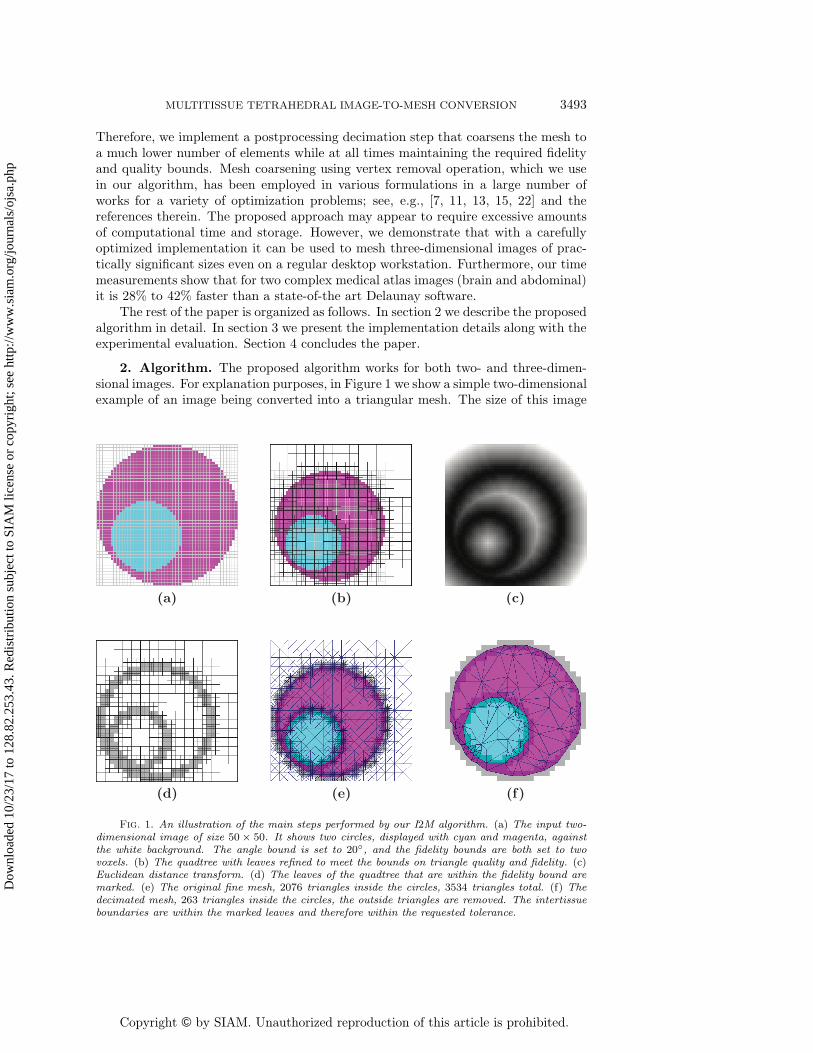
2. Algorithm. The proposed algorithm works for both two- and three-dimen-sional images. For explanation purposes, in Figure 1 we show a simple two-dimensionalexample of an image being converted into a triangular mesh. The size of this image
)c()b()a(
)f()e()d(
Fig. 1. An illustration of the main steps performed by our I2M algorithm. (a) The input two-dimensional image of size 50× 50. It shows two circles, displayed with cyan and magenta, againstthe white background. The angle bound is set to 20◦, and the fidelity bounds are both set to twovoxels. (b) The quadtree with leaves refined to meet the bounds on triangle quality and fidelity. (c)Euclidean distance transform. (d) The leaves of the quadtree that are within the fidelity bound aremarked. (e) The original fine mesh, 2076 triangles inside the circles, 3534 triangles total. (f) Thedecimated mesh, 263 triangles inside the circles, the outside triangles are removed. The intertissueboundaries are within the marked leaves and therefore within the requested tolerance.
3494 ANDREY N. CHERNIKOV AND NIKOS P. CHRISOCHOIDES
I
M H(M → I) H(I → M)
I
M
H(M → I)
H(I → M)
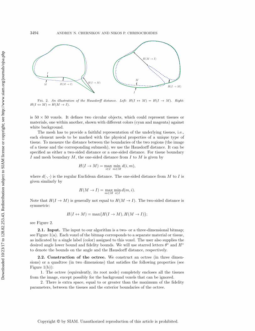
Fig. 2. An illustration of the Hausdorff distance. Left: H(I ↔ M) = H(I → M). Right:H(I ↔ M) = H(M → I).
is 50 × 50 voxels. It defines two circular objects, which could represent tissues ormaterials, one within another, shown with different colors (cyan and magenta) againstwhite background.
The mesh has to provide a faithful representation of the underlying tissues, i.e.,each element needs to be marked with the physical properties of a unique type oftissue. To measure the distance between the boundaries of the two regions (the imageof a tissue and the corresponding submesh), we use the Hausdorff distance. It can bespecified as either a two-sided distance or a one-sided distance. For tissue boundaryI and mesh boundary M , the one-sided distance from I to M is given by
H(I → M) = maxi∈I
minm∈M
d(i,m),
where d(·, ·) is the regular Euclidean distance. The one-sided distance from M to I isgiven similarly by
H(M → I) = maxm∈M
mini∈I
d(m, i).
Note that H(I → M) is generally not equal to H(M → I). The two-sided distance issymmetric:
H(I ↔ M) = max{H(I → M), H(M → I)};see Figure 2.
2.1. Input. The input to our algorithm is a two- or a three-dimensional bitmap;see Figure 1(a). Each voxel of the bitmap corresponds to a separate material or tissue,as indicated by a single label (color) assigned to this voxel. The user also supplies thedesired angle lower bound and fidelity bounds. We will use starred letters θ∗ and H∗
to denote the bounds on the angle and the Hausdorff distance, respectively.
2.2. Construction of the octree. We construct an octree (in three dimen-sions) or a quadtree (in two dimensions) that satisfies the following properties (seeFigure 1(b)):
1. The octree (equivalently, its root node) completely encloses all the tissuesfrom the image, except possibly for the background voxels that can be ignored.
2. There is extra space, equal to or greater than the maximum of the fidelityparameters, between the tissues and the exterior boundaries of the octree.
3. The boundaries between the leaves correspond exactly to the boundariesbetween the voxels. This is possible by using integer coordinates corresponding tovoxel indices.
4. No leaf contains voxels from multiple tissues. The nodes of the tree are splitrecursively until all the leaves satisfy this condition.
5. The sizes of the octree leaves respect the 2-to-1 rule, i.e., two adjacent leavesmust differ in depth by no more than one.
2.3. Computation of the distance transform. A distance transform of animage is an assignment to every voxel of a distance to the nearest feature of theimage. In our case, the features are the boundaries between the tissues, and thedistance is measured in the usual Euclidean metric. See, e.g., Figure 1(c), wheredarker shades correspond to the voxels that are closer to tissue boundaries. Weimplemented the Euclidean distance transform (EDT) algorithm described by Maurer,Qi, and Raghavan [12]. We chose this algorithm for two reasons: (1) its linear timecomplexity with respect to the number of voxels, and (2) it is formulated to work inan arbitrary dimension. We run the EDT computation on the extended image, i.e.,the image is padded with imaginary background voxels (or truncated of the extrabackground voxels) to the size of the octree root node.
2.4. Labeling of octree leaves. For each leaf of the octree, we find the max-imum distance to the intertissue boundaries, using the EDT values of the voxels en-closed by this leaf. In Figure 1(d) we marked the leaves that are within the tolerance(two voxels in this example) in transparent gray.
2.5. Filling in the octree. We process the leaves in the order of their size, start-ing with the smallest; see Figure 1(e) for a two-dimensional example. The procedureis recursive on dimension: to triangulate an n-dimensional face of the leaf, first trian-gulate all of its (n−1)-dimensional sub-faces. If at least one of the (n−1)-dimensionalsub-faces is split by a midpoint, introduce the midpoint of the n-dimensional face andconnect to the elements of the (n − 1)-dimensional triangulation of the sub-face toconstruct the n-dimensional triangulation of the face. If none of the sub-faces wassplit, use the diagonals of the face.
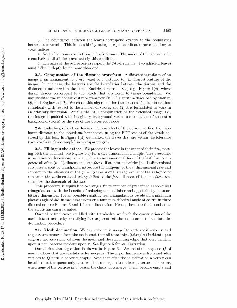
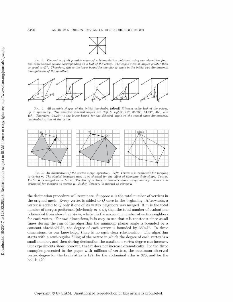
This procedure is equivalent to using a finite number of predefined canonic leaftriangulations, with the benefits of reducing manual labor and applicability in an ar-bitrary dimension. For all possible resulting leaf triangulations we obtain a minimumplanar angle of 45◦ in two dimensions or a minimum dihedral angle of 35.26◦ in threedimensions; see Figures 3 and 4 for an illustration. Hence, these are the bounds thatthe algorithm can guarantee.
Once all octree leaves are filled with tetrahedra, we finish the construction of themesh data structure by identifying face-adjacent tetrahedra, in order to facilitate thedecimation procedure.
2.6. Mesh decimation. We say vertex u is merged to vertex v if vertex u andedge uv are removed from the mesh, such that all tetrahedra (triangles) incident uponedge uv are also removed from the mesh and the remaining edges that were incidentupon u now become incident upon v. See Figure 5 for an illustration.
Our decimation algorithm is shown in Figure 6. We maintain a queue Q ofmesh vertices that are candidates for merging. The algorithm removes from and addsvertices to Q until it becomes empty. Note that after the initialization a vertex canbe added on the queue only as a result of a merge of an adjacent vertex. Therefore,when none of the vertices in Q passes the check for a merge, Q will become empty and
3496 ANDREY N. CHERNIKOV AND NIKOS P. CHRISOCHOIDES
Fig. 3. The union of all possible edges of a triangulation obtained using our algorithm for atwo-dimensional square corresponding to a leaf of the octree. The edges meet at angles greater thanor equal to 45◦. Therefore, this is the lower bound for the planar angle in the initial two-dimensionaltriangulation of the quadtree.
Fig. 4. All possible shapes of the initial tetrahedra (abcd) filling a cubic leaf of the octree,up to symmetry. The smallest dihedral angles are (left to right): 45◦, 35.26◦, 54.74◦, 45◦, and45◦. Therefore, 35.26◦ is the lower bound for the dihedral angle in the initial three-dimensionaltetrahedralization of the octree.
u
vw
v(u)w w(u,v)
Fig. 5. An illustration of the vertex merge operation. Left: Vertex u is evaluated for mergingto vertex v. The shaded triangles need to be checked for the effect of changing their shape. Center:Vertex u is merged to vertex v. The list of vertices in brackets shows merge history. Vertex v isevaluated for merging to vertex w. Right: Vertex v is merged to vertex w.
the decimation procedure will terminate. Suppose n is the total number of vertices inthe original mesh. Every vertex is added to Q once in the beginning. Afterwards, avertex is added to Q only if one of its vertex neighbors was merged. If m is the totalnumber of merges performed (obviously m < n), then the total number of evaluationsis bounded from above by n+cm, where c is the maximum number of vertex neighborsfor each vertex. For two dimensions, it is easy to see that c is constant: since at alltimes during the run of the algorithm the minimum planar angle is bounded by aconstant threshold θ∗, the degree of each vertex is bounded by 360/θ∗. In threedimensions, to our knowledge, there is no such clear relationship. The algorithmstarts with a semi-regular filling of the octree in which the degree of each vertex is asmall number, and then during decimation the maximum vertex degree can increase.Our experiments show, however, that it does not increase dramatically. For the threeexamples presented in the paper with millions of vertices, the maximum observedvertex degree for the brain atlas is 187, for the abdominal atlas is 326, and for theball is 420.
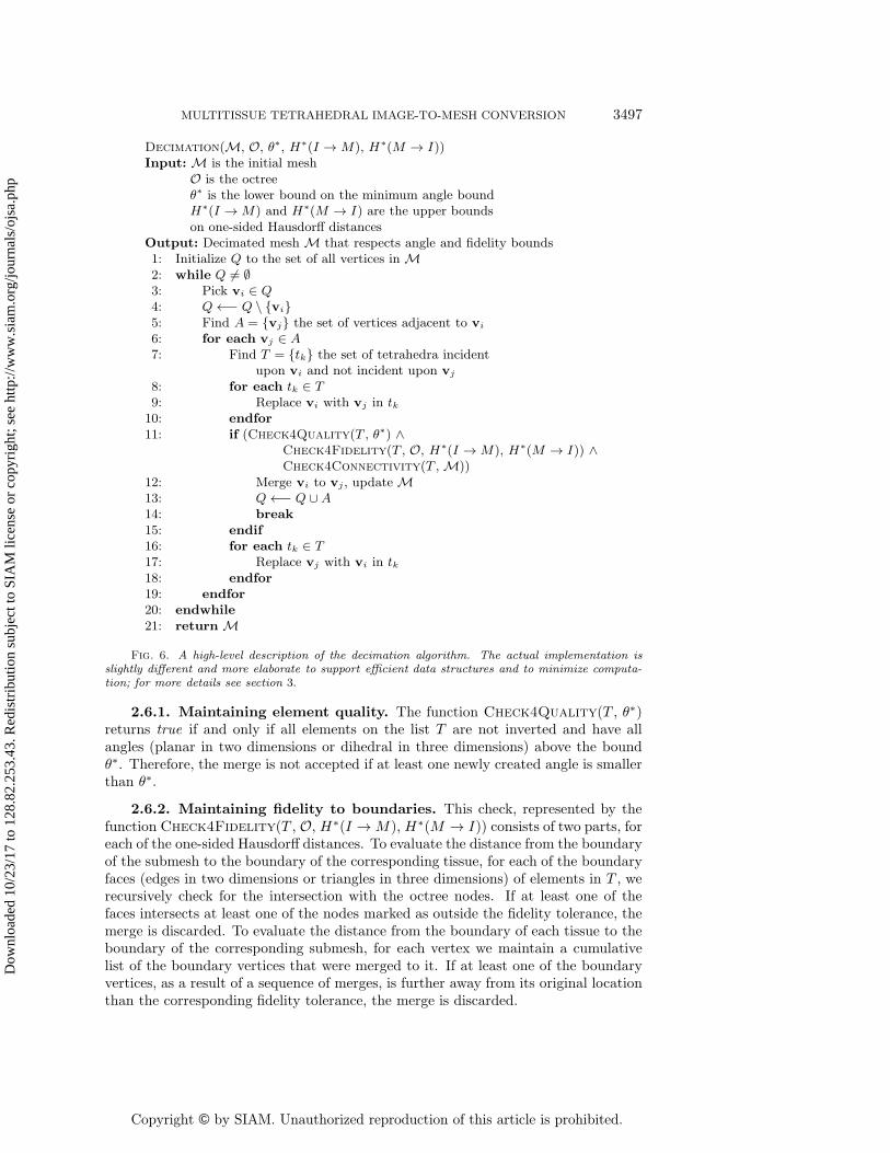
Decimation(M, O, θ∗, H∗(I → M), H∗(M → I))Input:M is the initial mesh
O is the octreeθ∗ is the lower bound on the minimum angle boundH∗(I →M) and H∗(M → I) are the upper boundson one-sided Hausdorff distances
Output: Decimated meshM that respects angle and fidelity bounds1: Initialize Q to the set of all vertices inM2: while Q �= ∅3: Pick vi ∈ Q4: Q←− Q \ {vi}5: Find A = {vj} the set of vertices adjacent to vi
6: for each vj ∈ A7: Find T = {tk} the set of tetrahedra incident
upon vi and not incident upon vj
8: for each tk ∈ T9: Replace vi with vj in tk
10: endfor11: if (Check4Quality(T , θ∗) ∧
Check4Fidelity(T , O, H∗(I →M), H∗(M → I)) ∧Check4Connectivity(T ,M))
12: Merge vi to vj , updateM13: Q←− Q ∪A14: break15: endif16: for each tk ∈ T17: Replace vj with vi in tk18: endfor19: endfor20: endwhile21: returnM
Fig. 6. A high-level description of the decimation algorithm. The actual implementation isslightly different and more elaborate to support efficient data structures and to minimize computa-tion; for more details see section 3.
2.6.1. Maintaining element quality. The function Check4Quality(T , θ∗)returns true if and only if all elements on the list T are not inverted and have allangles (planar in two dimensions or dihedral in three dimensions) above the boundθ∗. Therefore, the merge is not accepted if at least one newly created angle is smallerthan θ∗.
2.6.2. Maintaining fidelity to boundaries. This check, represented by thefunction Check4Fidelity(T , O, H∗(I → M), H∗(M → I)) consists of two parts, foreach of the one-sided Hausdorff distances. To evaluate the distance from the boundaryof the submesh to the boundary of the corresponding tissue, for each of the boundaryfaces (edges in two dimensions or triangles in three dimensions) of elements in T , werecursively check for the intersection with the octree nodes. If at least one of thefaces intersects at least one of the nodes marked as outside the fidelity tolerance, themerge is discarded. To evaluate the distance from the boundary of each tissue to theboundary of the corresponding submesh, for each vertex we maintain a cumulativelist of the boundary vertices that were merged to it. If at least one of the boundaryvertices, as a result of a sequence of merges, is further away from its original locationthan the corresponding fidelity tolerance, the merge is discarded.
3498 ANDREY N. CHERNIKOV AND NIKOS P. CHRISOCHOIDES
2.6.3. Maintaining tissue connectivity. The geometric constructions used inour algorithm are assigned colors based on their location with respect to the tissueson the bitmap:
1. Each leaf of the octree (quadtree) derives the color from the block of voxelsthat it encloses. Remember that the nodes are split recursively until they enclosevoxels of a single color; in the limit case a leaf encloses a single voxel.
2. Each tetrahedron in three dimensions (or triangle in two dimensions) derivesits color from the octree (quadtree) leaf that is used to tetrahedralize; it keeps theoriginal color even after it changes shape due to vertex merge. As a result, all tetra-hedra (triangles) are always correctly classified with respect to the underlying tissues,including the quadruple-zero (triple-zero) ones.
3. Each vertex derives its color from the block of incident voxels (eight in threedimensions or four in two dimensions); if the block of voxels has multiple colors, thevertex is considered boundary.
The following rules help us maintain the original structure of the intertissueboundaries: (1) boundary vertices cannot merge to nonboundary vertices, (2) a ver-tex cannot merge to a nonboundary vertex of a different color, and (3) a boundaryvertex can merge to another boundary vertex only along a boundary edge—this helpsto prevent the case when a vertex from one boundary merges to another boundaryalong a nonboundary edge, and thus the merge connects the parts of the boundariesthat were not originally connected.
3. Implementation and evaluation. We implemented the proposed latticedecimation (LD) algorithm in C++, in both two and three dimensions. The followingimplementation decisions have significantly improved the performance:
1. Most of the computation is performed in integer arithmetic. This is possiblebecause vertex coordinates are integers; they are indices with respect to the matrix ofvoxels. The only floating point computation is involved in the comparison of cosinesof angles since long integer arithmetic could overflow. In addition, the lengths ofthe integer variables correspond to the range of values of each specific arithmeticoperation, such that very long integers are used only when necessary to avoid overflow.For example, if variable x is represented with b bits, then x2 requires 2b bits, whilex4 requires 4b bits; using 4b bits for x2 would be excessive.
2. All expensive mathematical functions, such as trigonometric, square root,etc., including floating point division, are avoided in the computationally criticalparts. Instead, computation is performed on squares, cosines, and other functions ofthe original values.
3. We wrote customized memory allocation functions, such that objects that arecreated in large numbers but occupy little memory each (vertices, tetrahedra, nodesof the tree) are allocated in contiguous memory buffers. This improvement decreasesmemory fragmentation and allocation overheads.
4. We arranged the sequences of complex pass-fail condition evaluations suchthat the least expensive conditions and those most likely to fail are evaluated first,while the most expensive ones are evaluated last.
Clearly, the performance of our algorithm in terms of the running time, as wellas the number and the size of tetrahedra, depends on the input geometry. There-fore, our approach to the evaluation is based on two experimental setups. The firstsetup uses a very simple three-dimensional geometry (sphere) and evaluates the per-formance with respect to different sizes of the sphere. This way, we gain insightinto the performance for a controlled range of domain geometries with varied ratio
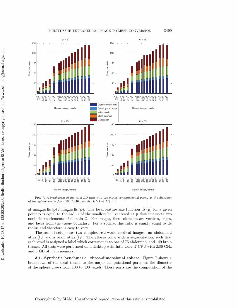
Fig. 7. A breakdown of the total LD time into the major computational parts, as the diameterof the sphere varies from 100 to 400 voxels. H∗(I ↔ M) = 0.
of maxp∈Ω lfs (p) /minp∈Ω lfs (p). The local feature size function lfs (p) for a givenpoint p is equal to the radius of the smallest ball centered at p that intersects twononincident elements of domain Ω. For images, these elements are vertices, edges,and faces from the tissue boundary. For a sphere, this ratio is simply equal to itsradius and therefore is easy to vary.
The second setup uses two complex real-world medical images: an abdominalatlas [18] and a brain atlas [19]. The atlases come with a segmentation, such thateach voxel is assigned a label which corresponds to one of 75 abdominal and 149 braintissues. All tests were performed on a desktop with Intel Core i7 CPU with 2.80 GHzand 8 GB of main memory.
3.1. Synthetic benchmark—three-dimensional sphere. Figure 7 shows abreakdown of the total time into the major computational parts, as the diameterof the sphere grows from 100 to 400 voxels. These parts are the computation of the
3500 ANDREY N. CHERNIKOV AND NIKOS P. CHRISOCHOIDES
distance transform, the construction of the octree, the construction of the initial meshthat fills the leaves of the octree, the finding of the connectivity among the tetrahedraof the initial mesh (which is expensive because involves a search through the adjacentleaves), and the decimation. Here and in all other time measurements we exclude thetime taken by input and output and by the process of initializing the data structurerepresenting the initial image. We conclude that all components represented in thefigure grow approximately linear with respect to the total number of voxels in theimage, while the sharp jump between the diameter values of 250 and 275 correspondsto the increase of the octree size which can only take values of powers of two.
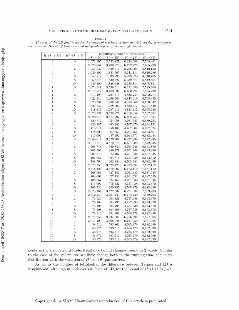
Table 1 shows the output mesh size of our implementation for a sphere of a fixeddiameter of 400 voxels. In these tests, having fixed the dihedral angle bound and thediameter of the sphere, we vary each of the two one-sided Hausdorff distance boundparameters independently. We present four columns, for different interesting valuesof the dihedral angle bound (5◦, 15◦, 25◦, and 35◦) spread through the range of itsfeasible values (0◦ to 35.26◦). As we can see from Table 1, for all configurationsthe output mesh size is high when either one or both of the H∗ parameters is low(H∗(M → I) has higher influence than H∗(I → M) due to implementation-specificdetails) and decreases as the H∗ bounds decrease. Indeed, the weaker constraints canbe satisfied with a smaller number of tetrahedra. The same argument explains whythe final number of tetrahedra grows as the dihedral angle bound increases. The totalrunning time in these tests does not change significantly with the variation of thefidelity bounds and is close to 250 seconds. The actually obtained smallest dihedralangles in all experiments are between θ∗ and θ∗ + 0.3◦.
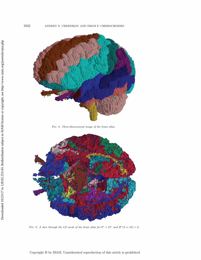
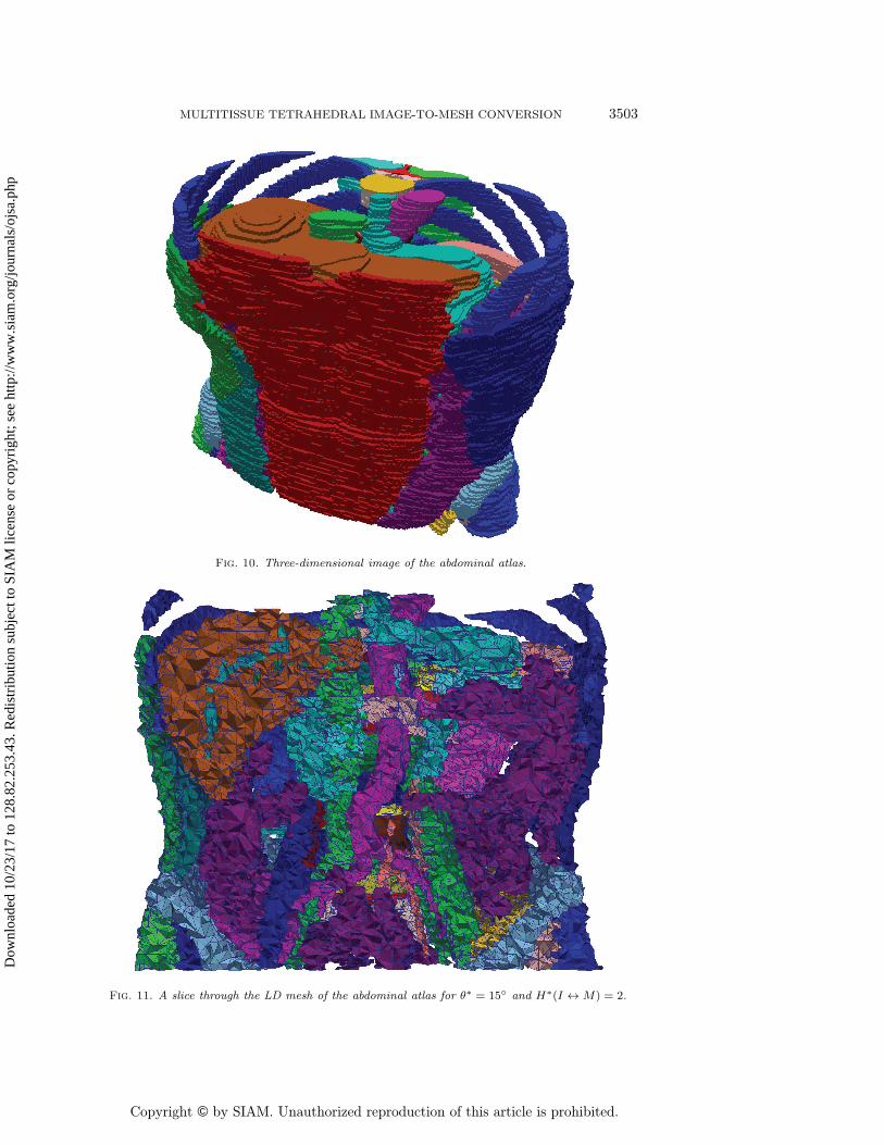
3.2. Three-dimensional medical images. The size of the abdominal atlas is256 × 256 × 113 voxels and the size of the brain atlas is 256 × 256 × 159 voxels. Inboth cases each voxel has side lengths of 0.9375, 0.9375, and 1.5000 units in x, y, andz directions, respectively. Before meshing the atlases, we resampled them with voxelsof equal side length corresponding to the original 0.9375 units. As a result, in bothcases we obtained equally spaced images that were used for meshing. Figures 8, 9, 10and 11 show the atlas images and corresponding three-dimensional meshes.
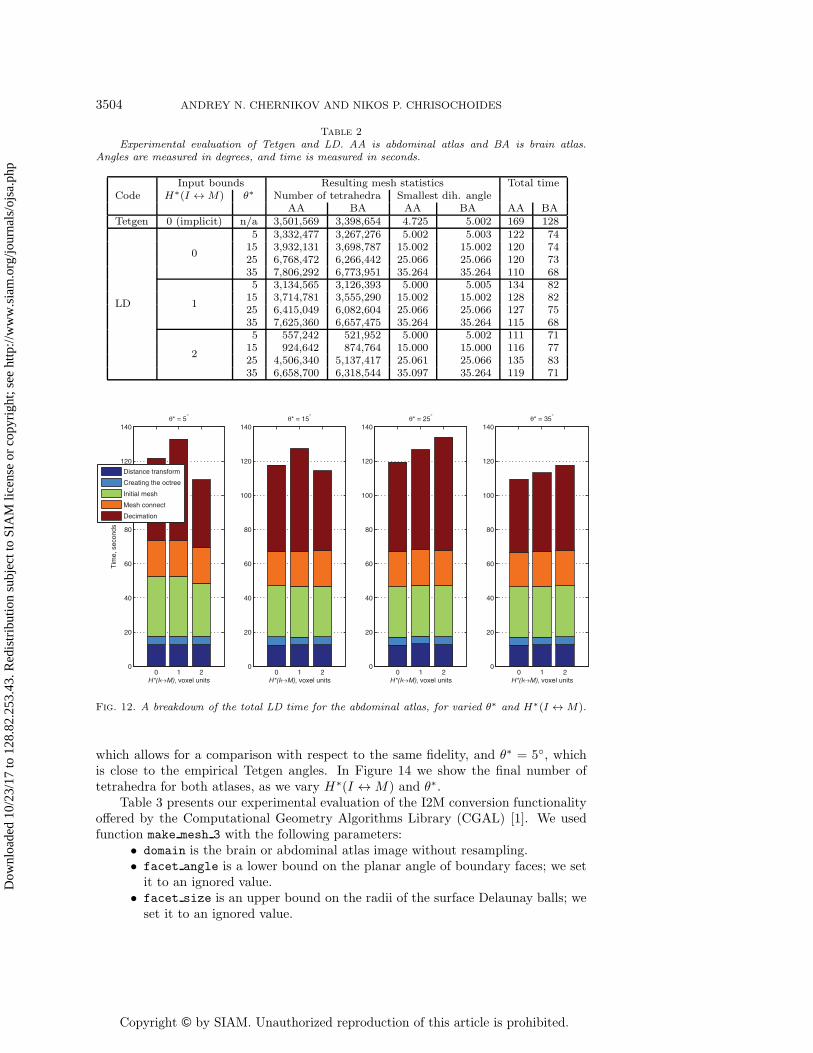
In Table 2 we list the final number of tetrahedra, the smallest dihedral angle,and the total running time for both images, as we vary the H∗ and θ∗ parameters.To obtain a point of reference for these numbers, we conducted a separate exper-iment using a state-of-the art open source tetrahedral mesh generator Tetgen [16].Tetgen is designed to work with piecewise linear complexes (PLCs) and not images.Therefore, to make it process the same tissue geometries, we extracted the voxel facescorresponding to the boundaries between different tissues and between the tissuesand the surrounding space and saved them in the PLC format files that we passedto Tetgen. The main difference between the two methods is that Tetgen does notprovide any guarantees on the dihedral angle (since it is designed to improve onlycircumradius-to-shortest-edge ratio of tetrahedra for general PLCs), and its empiricalsmallest dihedral angle will generally be different for other input geometries. As canbe expected, the meshes produced by Tetgen had low smallest dihedral angles, around5◦. At the same time, our LD algorithm can provide guaranteed smallest dihedralangles up to 35.26◦ for all input images.
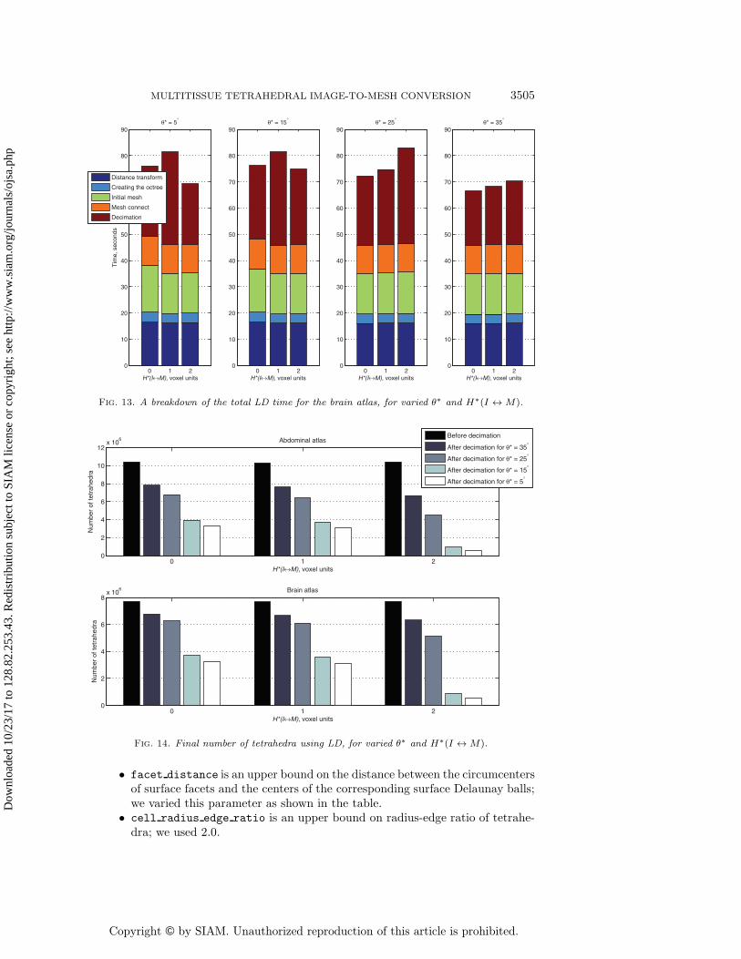
For all our time measurements we excluded all data preprocessing, such as imageresampling, surface extraction, and input and output. We see that our LD implemen-tation is faster than Tetgen by a significant margin for both atlas images. Figures 12and 13 show breakdowns of the total LD time into the main computational compo-
The size of the LD final mesh for the image of a sphere of diameter 400 voxels, depending onthe one-sided Hausdorff bounds varied independently, and on the angle bound.
nents as the symmetric Hausdorff distance bound changes from 0 to 2 voxels. Similarto the case of the sphere, we see little change both in the running time and in itsdistribution with the variation of H∗ and θ∗ parameters.
As far as the number of tetrahedra, the difference between Tetgen and LD isinsignificant, although in both cases in favor of LD, for the bound of H∗(I ↔ M) = 0
Fig. 12. A breakdown of the total LD time for the abdominal atlas, for varied θ∗ and H∗(I ↔ M).
which allows for a comparison with respect to the same fidelity, and θ∗ = 5◦, whichis close to the empirical Tetgen angles. In Figure 14 we show the final number oftetrahedra for both atlases, as we vary H∗(I ↔ M) and θ∗.
Table 3 presents our experimental evaluation of the I2M conversion functionalityoffered by the Computational Geometry Algorithms Library (CGAL) [1]. We usedfunction make mesh 3 with the following parameters:
• domain is the brain or abdominal atlas image without resampling.• facet angle is a lower bound on the planar angle of boundary faces; we set
it to an ignored value.• facet size is an upper bound on the radii of the surface Delaunay balls; weset it to an ignored value.
Fig. 13. A breakdown of the total LD time for the brain atlas, for varied θ∗ and H∗(I ↔ M).
0 1 20
2
4
6
8
10
12x 10
6
H*(I↔M), voxel units
Num
ber
of te
trah
edra
Abdominal atlasBefore decimation
After decimation for θ* = 35°
After decimation for θ* = 25°
After decimation for θ* = 15°
After decimation for θ* = 5°
0 1 20
2
4
6
8x 10
6
H*(I↔M), voxel units
Num
ber
of te
trah
edra
Brain atlas
Fig. 14. Final number of tetrahedra using LD, for varied θ∗ and H∗(I ↔ M).
• facet distance is an upper bound on the distance between the circumcentersof surface facets and the centers of the corresponding surface Delaunay balls;we varied this parameter as shown in the table.
• cell radius edge ratio is an upper bound on radius-edge ratio of tetrahe-dra; we used 2.0.
3506 ANDREY N. CHERNIKOV AND NIKOS P. CHRISOCHOIDES
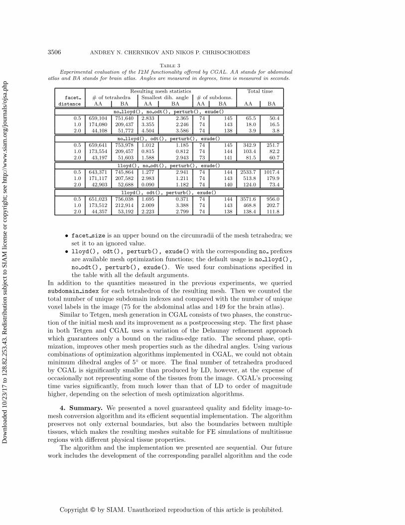
Table 3
Experimental evaluation of the I2M functionality offered by CGAL. AA stands for abdominalatlas and BA stands for brain atlas. Angles are measured in degrees, time is measured in seconds.
Resulting mesh statistics Total timefacet # of tetrahedra Smallest dih. angle # of subdoms.
• facet size is an upper bound on the circumradii of the mesh tetrahedra; weset it to an ignored value.
• lloyd(), odt(), perturb(), exude() with the corresponding no prefixesare available mesh optimization functions; the default usage is no lloyd(),
no odt(), perturb(), exude(). We used four combinations specified inthe table with all the default arguments.
In addition to the quantities measured in the previous experiments, we queriedsubdomain index for each tetrahedron of the resulting mesh. Then we counted thetotal number of unique subdomain indexes and compared with the number of uniquevoxel labels in the image (75 for the abdominal atlas and 149 for the brain atlas).
Similar to Tetgen, mesh generation in CGAL consists of two phases, the construc-tion of the initial mesh and its improvement as a postprocessing step. The first phasein both Tetgen and CGAL uses a variation of the Delaunay refinement approachwhich guarantees only a bound on the radius-edge ratio. The second phase, opti-mization, improves other mesh properties such as the dihedral angles. Using variouscombinations of optimization algorithms implemented in CGAL, we could not obtainminimum dihedral angles of 5◦ or more. The final number of tetrahedra producedby CGAL is significantly smaller than produced by LD, however, at the expense ofoccasionally not representing some of the tissues from the image. CGAL’s processingtime varies significantly, from much lower than that of LD to order of magnitudehigher, depending on the selection of mesh optimization algorithms.
4. Summary. We presented a novel guaranteed quality and fidelity image-to-mesh conversion algorithm and its efficient sequential implementation. The algorithmpreserves not only external boundaries, but also the boundaries between multipletissues, which makes the resulting meshes suitable for FE simulations of multitissueregions with different physical tissue properties.
The algorithm and the implementation we presented are sequential. Our futurework includes the development of the corresponding parallel algorithm and the code
to increase the processing speed and the size of the images that can be handled. Onestage of the algorithm, the distance transform, has already been parallelized [17].However, according to Amdahl’s law, to achieve good speedup, we need to parallelizethe other stages as well. We also plan to address the smoothness of mesh boundariesin order to improve the accuracy of such simulations as blood flow.
Acknowledgments. We thank the anonymous reviewers for detailed commentswhich helped us improve the manuscript.
REFERENCES
[1] Computational Geometry Algorithms Library, http://www.cgal.org.[2] D. Boltcheva, M. Yvinec, and J.-D. Boissonnat, Mesh generation from 3d multi-material
images, in Proceedings of the 12th International Conference on Medical Image Computingand Computer-Assisted Intervention: Part II, Springer-Verlag, Berlin, 2009, pp. 283–290.
[3] S.-W. Cheng, T. K. Dey, H. Edelsbrunner, M. A. Facello, and S.-H. Teng, Sliver exu-dation, J. ACM, 47 (2000), pp. 883–904.
[4] L. P. Chew, Guaranteed-quality Delaunay meshing in 3D, in Proceedings of the 13th ACMSymposium on Computational Geometry, Nice, France, 1997, pp. 391–393.
[5] A. Fedorov and N. Chrisochoides, Tetrahedral mesh generation for non-rigid registrationof brain MRI: Analysis of the requirements and evaluation of solutions, in Proceedings ofthe 17th International Meshing Roundtable, Pittsburgh, PA, 2008, Springer-Verlag, Berlin,pp. 55–72.
[6] P.-L. George and H. Borouchaki, Delaunay Triangulation and Meshing. Application toFinite Elements, Hermes, Paris, 1998.
[7] H. Hoppe, T. DeRose, T. Duchamp, J. McDonald, and W. Stuetzle, Mesh optimization,in Proceedings of the 20th Annual Conference on Computer Graphics and InteractiveTechniques, New York, 1993, ACM, pp. 19–26.
[8] F. Labelle and J. R. Shewchuk, Isosurface stuffing: Fast tetrahedral meshes with good di-hedral angles, ACM Transactions on Graphics, 26 (2007), pp. 57.1–57.10.
[9] X.-Y. Li and S.-H. Teng, Generating well-shaped Delaunay meshes in 3D, in Proceedings ofthe 12th Annual ACM-SIAM Symposium on Discrete Algorithms, Washington, DC, 2001,pp. 28–37.
[10] Y. Liu, P. Foteinos, A. Chernikov, and N. Chrisochoides, Multi-tissue mesh generation forbrain images, in Proceedings of the 19th International Meshing Roundtable, Chattanooga,TN, Springer-Verlag, Berlin, 2011, pp. 367–384.
[11] D. P. Luebke, A developer’s survey of polygonal simplification algorithms, IEEE Comput.Graph. Appl., 21 (2001), pp. 24–35.
[12] C. Maurer, R. Qi, and V. Raghavan, A linear time algorithm for computing exact Euclideandistance transforms of binary images in arbitrary dimensions, IEEE Trans. Pattern Anal.Machine Intel., 25 (2003), pp. 265–270.
[13] R. Pajarola and J. Rossignac, Compressed progressive meshes, IEEE Trans. VisualizationComput. Graphics, 6 (2000), pp. 79–93.
[14] J.-P. Pons, F. Segonne, J.-D. Boissonnat, L. Rineau, M. Yvinec, and R. Keriven, High-quality consistent meshing of multi-label datasets, in Proceedings of the 20th InternationalConference on Information Processing in Medical Imaging, 2007, Springer-Verlag, Berlin,pp. 198–210.
[15] W. J. Schroeder, J. A. Zarge, and W. E. Lorensen, Decimation of triangle meshes, in Pro-ceedings of the 19th Annual Conference on Computer Graphics and Interactive Techniques,New York, 1992, ACM, pp. 65–70.
[16] H. Si, Tetgen Version 1.4.3, http://tetgen.berlios.de.[17] R. Staubs, A. Fedorov, L. Linardakis, B. Dunton, and N. Chrisochoides, Parallel n-
dimensional exact signed Euclidean distance transform, Insight J., 2006.[18] I. Talos, M. Jakab, and R. Kikinis, SPL Abdominal Atlas 2010, http://www.spl.harvard.edu/
publications/item/view/1918 (Oct. 2010).[19] I. Talos, M. Jakab, R. Kikinis, and M. Shenton, SPL-PNL Brain Atlas, http://www.spl.
harvard.edu/publications/item/view/1265 (March 2008).[20] J. F. Thompson, B. K. Soni, and N. P. Weatherill, Handbook of Grid Generation, CRC
3508 ANDREY N. CHERNIKOV AND NIKOS P. CHRISOCHOIDES
[21] J. Tournois, R. Srinivasan, and P. Alliez, Perturbing slivers in 3D Delaunay meshes, inProceedings of the 18th International Meshing Roundtable, B. W. Clark, ed., Springer-Verlag, Berlin, 2009, pp. 157–173.
[22] J. Yan, P. Shi, and D. Zhang, Mesh simplification with hierarchical shape analysis and iter-ative edge contraction, IEEE Trans. Visualization Comput. Graphics, 10 (2004), pp. 142–151.
[23] O. C. Zienkiewicz, R. L. Taylor, and J. Z. Zhu, The Finite Element Method: Its Basis andFundamentals, 6th ed., Butterworth-Heinemann, London, 2005.