1 Multiuser Detection for Out-of-Cell Cochannel Interference Mitigation in the IS–95 Downlink D. Richard Brown III, H. Vincent Poor, Sergio Verd´ u, and C. Richard Johnson, Jr. This research was supported in part by NSF grants ECS-9811297, ECS-9811095, EEC-9872436, and Applied Signal Technology. D.R. Brown III is with the Department of Electrical and Computer Engineering, Worcester Polytechnic Institute, Worcester, MA 01609, USA. H.V. Poor and S. Verd´ u are with the Department of Electrical Engineering, Princeton University, Princeton, NJ 08544 USA. C.R. Johnson, Jr. is with the School of Electrical Engineering, Cornell University, Ithaca, NY 14853 USA. September 19, 2001 DRAFT
Transcript
1
Multiuser Detection for Out-of-Cell
Cochannel Interference Mitigation in the
IS–95 Downlink
D. Richard Brown III, H. Vincent Poor, Sergio Verdu, and C. Richard
Johnson, Jr.
This research was supported in part by NSF grants ECS-9811297, ECS-9811095, EEC-9872436, and Applied
Signal Technology. D.R. Brown III is with the Department of Electrical and Computer Engineering, Worcester
Polytechnic Institute, Worcester, MA 01609, USA. H.V. Poor and S. Verdu are with the Department of Electrical
Engineering, Princeton University, Princeton, NJ 08544 USA. C.R. Johnson, Jr. is with the School of Electrical
Engineering, Cornell University, Ithaca, NY 14853 USA.
September 19, 2001 DRAFT
Abstract
This paper considers the application of multiuser detection techniques to improve the quality of
downlink reception in a multi-cell IS–95 digital cellular communication system. In order to understand the
relative performance of suboptimum multiuser detectors including the matched filter detector, optimum
multiuser detection in the context of the IS–95 downlink is first considered. A reduced complexity optimum
detector that takes advantage of the structural properties of the IS–95 downlink and exhibits exponentially
lower complexity than the brute-force optimum detector is developed. The Group Parallel Interference
Cancellation (GPIC) detector, a suboptimum, low-complexity multiuser detector that also exploits the
structure of the IS–95 downlink is then developed. Simulation evidence is presented that suggests that
the performance of the GPIC detector may be near-optimum in several cases. The GPIC detector is also
tested on a snapshot of on-air data measured with an omnidirectional antenna in an active IS–95 system
and is shown to be effective for extracting weak downlink transmissions from strong out-of-cell cochannel
interference. The results of this paper suggest that the GPIC detector offers the most performance gain
in scenarios where weak downlink signals are corrupted by strong out-of-cell cochannel interference.
I. Introduction
An important milestone in the development of personal wireless communication systems
occurred in the early 1990’s when Qualcomm introduced a new digital cellular communica-
tion system based on Code Division Multiple Access (CDMA) technology. The proposed
cellular system offered several advantages over first generation analog cellular systems in-
cluding increased capacity and reliability as well as improved sound quality and battery
life. Early trials of this new cellular system proved to be quite successful and, in 1993, the
details of the system were published by the Telecommunications Industry Association as
the IS–95A standard [1].
Despite the well documented performance benefits of multiuser detection in the liter-
ature prior to 1993, the IS–95 cellular standard was designed such that adequate per-
formance could be achieved by a downlink receiver (typically a mobile handset) using
conventional single-user matched filter detection with coherent multipath combining. The
choice of matched filter detection for the IS–95 downlink resulted in the need for strict,
closed-loop power control on both the uplink and downlink in order to avoid “near-far”
problems (cf. [2]). One reason for this approach is that, unlike power control, the majority
of the multiuser detectors proposed in the literature have been regarded as too complex for
cost-effective implementation in IS–95 downlink receivers. Despite the exponential perfor-
mance improvements in microprocessors and DSPs over the last decade, these constraints
have continued to outweigh the potential performance benefits of multiuser detection for
the IS–95 downlink.
In this paper we attempt to bridge some of the gap between IS–95 and multiuser de-
tection. Toward that goal, several authors have studied the problem of improving the
performance of IS-95 and third generation Wideband-CDMA downlink reception in a
single-cell environment. In [3]–[12] the authors observe that the orthogonality of the user
transmissions within a particular cell is destroyed by multiple paths in the propagation
channel between the base station and the IS–95 downlink receiver. The authors propose
receivers that all share the common feature of a linear equalizer front-end that cancels
the effects of the multipath propagation channel and restores the orthogonality of the
users. This approach effectively eliminates the in-cell multiuser interference and allows
the conventional matched filter detector to be used. In [13], the authors propose and com-
pare several algorithms applicable to the IS–95 downlink for multipath channel estimation.
In [14], [15], the authors developed a nonlinear multipath canceller to cancel the in-cell
multiuser interference caused by multipath replicas of the base station’s pilot signal.
Our approach here differs from the prior approaches in that we investigate multiuser
detection for the IS–95 downlink in a multi-cell environment. Multiuser detection in a
multi-cell environment was considered recently for the IS–95 uplink in [16], [17]. In this
paper we consider receivers that mitigate the effects of the out-of-cell cochannel interfer-
ence from neighboring base stations in the IS–95 downlink. To establish a performance
benchmark, we first examine optimum detection for the IS–95 downlink and develop a
reduced complexity optimum detector that exploits the structure of the IS–95 downlink.
We then propose the Group Parallel Interference Cancellation (GPIC) detector, a sub-
optimum, low-complexity multiuser detector that also exploits the structure of the IS–95
downlink.
The results of this paper suggest that multiuser detection may provide modest per-
formance improvements over the conventional matched filter detector in scenarios where
a strong desired signal is corrupted by weak out-of-cell cochannel interference. On the
other hand, our results suggest that multiuser detection may offer significant performance
improvements in conditions where an IS–95 downlink receiver is detecting a weak desired
signal in the presence of strong out-of-cell cochannel interference. Although this scenario
would be unusual for a subscribing user in an IS–95 cellular system, the practical impli-
cations of our results include:
• Nonsubscribing users (e.g. eavesdroppers or test/diagnostic receivers) which do not
have the benefit of power control may wish to extract a weak desired signal from
strong out-of-cell cochannel interference. Multiuser detection receivers tend to offer
superior performance in these cases.
• Subscribing users with multiuser detectors require less transmit power from their base
station to maintain an equal quality of service. This “good neighbor” effect leads to a
reduced level of cochannel interference induced on other out-of-cell users in the system.
This balance of this paper is organized as follows. In Section II we develop a concise
model with mild simplifying assumptions for the IS–95 downlink that includes the effects of
the time and phase asynchronous, nonorthogonal, and non-cyclostationary transmissions
of aM base station communication system. In Section III we use this model to understand
optimum multiuser detection in the context of the IS–95 downlink. Although the optimum
detector is often too complex for implementation in realistic systems, its role is still impor-
tant in order to determine the relative performance of suboptimum multiuser detectors. In
Section IV we show that the structure of the IS–95 downlink allows the optimum detector
to be posed in a computationally efficient form with complexity exponentially less than a
brute-force implementation. In Section V we develop a computationally efficient nonlinear
multiuser detector for the IS–95 downlink called the Group Parallel Interference Cancel-
lation (GPIC) detector. The GPIC detector is derived from examination of properties
of the reduced complexity optimum detector and also exploits the structure in the IS–95
downlink. In Section VI we examine the performance of the GPIC detector relative to
the conventional matched filter and optimum detectors via simulation and show that the
GPIC detector exhibits near-optimum performance in the cases examined and provides
the largest benefit when the desired signal is received in the presence of strong out-of-cell
cochannel interference. Finally, in Section VII we apply the GPIC detector to a snapshot
of on-air data from an active IS–95 system and present results that suggest that GPIC
detection offers significant performance improvements when extracting weak signals in the
presence of severe out-of-cell cochannel interference.
II. IS–95 Downlink System Model
Figure 1 shows a model of a single IS–95 base station downlink transmitter. This model
is simplified in the sense that the scrambling and channel encoding operations specified
by the IS–95 standard prior to the channelization block in Figure 1 are not shown. An
IS–95 downlink receiver typically consists of four fundamental stages: multipath timing
and phase estimation (via the downlink pilot), coded symbol detection (matched filter
with multipath combining), decoding (convolutional and repetition), and descrambling.
Since this paper focuses on the problem of improving the performance of the detection
stage, we consider the portion of the IS–95 downlink transmitter “inside the coders” as
shown in Figure 1.
Channelizer Power Control
PN-Code
Pulse Shaping
pilot:m
b(m,1)
b(m,Km)
Walsh Code
Walsh Code
Walsh Code
a(m,0)
a(m,1)
a(m,K1)
......
zm(t)
Fig. 1. Single base station IS–95 downlink baseband transmitter model.
We denote m as the base station index and Km as the number of data streams simul-
taneously transmitted by the mth base station, not including the pilot transmission. Note
that Km is typically greater than the actual number of physical users in the cell since
the IS–95 standard specifies that each base station must transmit additional data streams
for call setup, paging, and overhead information. For the purposes of this paper, we will
henceforth refer to each of these data streams as a “user” even if the data stream is an
overhead channel and not actually allocated to a particular user in the cell. The details
of Figure 1 as specified by the IS–95 standard may be summarized as follows:
• Channelizer: Orthogonalizes the user transmissions by assigning a unique length-64
Walsh code to each user and spreads the input symbols with this code. Each user’s
Walsh code remains fixed for the duration of their connection. The Walsh-0 code is
always assigned to the base station’s pilot signal which transmits a constant stream of
binary symbols equal to +1. The remaining 63 Walsh codes are assigned as needed to
the users in the cell as well as to overhead and paging channels.
• Power Control: Sets the gain on each user’s transmission to provide a minimum accept-
able transmission quality in order to avoid generating excessive cochannel interference
in neighboring cells.
• PN-Code: Multiplies the chip-rate aggregate base station data stream by a complex
pseudonoise (PN) code in order to cause the cochannel interference observed by the
users in neighboring cells to appear noiselike and random [18, pp. 11]. Each base
station uses the same PN-code but is distinguished by a unique, fixed PN-phase. The
PN-code has elements from the set 1 + j, 1 − j,−1 + j,−1 − j and has a period of
215 chips.
• Pulse Shaping: Specified in the IS–95 standard.
Note that the total spreading gain on the coded symbols in the IS–95 downlink is 64 and
that all spreading occurs in the channelizer block. The PN-code does not provide any
additional spreading.
Since the IS–95 standard specifies universal frequency reuse for all base stations in a
cellular system, it is reasonable to model the downlink receiver’s observation as the sum of
transmissions fromM base stations and additive channel noise as shown in Figure 2. Each
base station’s aggregate transmission passes through an individual propagation channel
that accounts for the effects of multipath, delay, and attenuation. The channel noise is
modeled as an additive, white, complex Gaussian random process denoted by σw(t) where
E(w(t)) = 0 and E(Re(w(t))2) = E(Im(w(t))2) = 1/2. The real and imaginary parts are
uncorrelated and also assumed to be independent of the base station transmissions.
z1(t)
z2(t)
zM(t)
Channel 1
Channel 2
Channel M
r(t)
σw(t)
...
Fig. 2. Baseband IS–95 downlink received signal model.
We define the total number of users in the system as K =∑M
m=1Km. To facilitate the
analytical development in the following sections, we also make the following simplifying
assumptions which may be relaxed or eliminated at the expense of greater notational
complexity:
• We ignore the soft-handoff feature of IS–95 where two base stations may be transmitting
identical bit streams to a single user.
• We assume the user population remains fixed over the receiver’s observation interval.
This implies that users do not enter or leave the system, users are not handed off
between cells, and that voice activity switching does not occur during the observation
interval.
• We ignore base station antenna sectorization.
Indexing the users by a two dimensional index (base station, user number), we denote
the (m, k)th user’s positive real amplitude and coded binary symbol at symbol index
as a(m,k)
and b(m,k)
respectively. We denote the unit-energy normalized combined impulse
response of the (m, k)th user’s channelization code, PN-code, baseband pulse shaping, and
propagation channel at symbol index as s(m,k)
(t). Note that s(m,k)
(t) includes any inherent
propagation delay and asynchronicity between base stations and is assumed to be FIR.
We also denote φm as the received phase of the transmission from the mth base station.
The baseband signal observed at the downlink receiver may then be written as
r(t) =M∑
m=1
ejφm
L∑=−L
[a(m,0)
s(m,0)
(t− T ) +Km∑k=1
b(m,k)
a(m,k)
s(m,k)
(t− T )
]+ σw(t).
where we have separated the terms corresponding to the non-data-bearing pilots with the
superscript notation (m, 0).
In order to represent the observation r(t) compactly, we establish the following vector
notation. If x(m,k)
represents a (possibly complex) scalar quantity corresponding to the
(m, k)th user at symbol index , we can construct the vectors
x[m]
=[x(m,1)
, . . . , x(m,Km)
],
x[m] =[x[m]−L , . . . ,x[m]
L
], and
x =[x[1], . . . ,x[M ]] .
The superscripts x, x∗ and xH denote transpose, complex conjugate, and complex con-
jugate transpose, respectively. Define a and b according to this notation and define the
vector of signature waveforms as
s[m]
(t− T ) =[s(m,1)
(t− T ), . . . , s(m,Km)
(t− T )]
,
s[m](t) =[s[m]−L (t+ LT ), . . . , s[m]
L (t− LT )]
, and
s(t) =[s[1](t), . . . , s[M ](t)
].
Finally, define
A = diag([ejφ1a[1], . . . , ejφM a[M ]])
as the K(2L+ 1)×K(2L+ 1) dimensional diagonal matrix of user amplitudes multiplied
by the appropriate base station transmission phases. We can then write the continuous
time observation as
r(t) =M∑
m=1
ejφm
L∑=−L
a(m,0)
s(m,0)
(t− T )
︸ ︷︷ ︸pilots
+ s(t)Ab︸ ︷︷ ︸users
+ σw(t)︸ ︷︷ ︸AWGN
= p(t) + s(t)Ab + σw(t)
(1)
where the pilots are denoted as p(t) for notational convenience.
III. Optimum Detection
In this section we examine optimum (joint maximum likelihood) detection in the context
of the previously developed IS–95 downlink system model. In a single-cell scenario with
single-path channels, an IS–95 downlink receiver observes the sum of K orthogonally
modulated signals in the presence of independent AWGN. It is easy to show that the
optimum detector is equivalent to the conventional single-user matched filter detector
in this case. In this paper, however, we consider the multi-cell scenario where an IS–
95 downlink receiver observes nonorthogonal out-of-cell cochannel interference and the
optimum detector is not the matched filter detector.
We assume that the receiver is able to acquire the pilot (and hence the PN-phase) of each
base station m ∈ 1, . . . ,M via correlation with the known periodic PN-code of length
215. This then allows the receiver to estimate the impulse response of the propagation
channel and transmission phases of each base station. For each base station, the receiver
can then construct a bank of 63 matched filters, one matched filter for each of the non-pilot
Walsh codes, in order to determine which users are active in each cell. Since the receiver
now knows the Walsh codes of the active users, the phase of the PN-code, the propagation
channels, and the baseband pulse-shaping, we can construct the set of s(m,k)
(t) for all users
in the multi-cell system. Finally, amplitude estimates are generated for each user and the
pilots (cf. [19]). For the purposes of the remaining analytical development, we assume that
all of these estimates are perfect and that the only unknowns in (1) are b and σw(t).
Let I represent a compact interval in time containing the support of r(t) and let Urepresent the set of cardinality 2K(2L+1) containing all admissible binary symbol vectors of
length K(2L+ 1). Then the jointly optimum symbol estimates [20] are given by
bOPT = argmaxu∈U
exp
(− 1
σ2
∫I|r(t)− p(t)− s(t)Au|2dt
).
Manipulation of the term inside the exponent yields the expression for jointly optimum
IS–95 downlink symbol estimates as
bOPT = argmaxu∈U
2Re[uAH(y − p)]− uAHRAu︸ ︷︷ ︸Ω(u)
where y =∫I s∗(t)r(t) dt represents the K(2L + 1)-vector of matched filter outputs, p =∫
I s∗(t)p(t) dt represents theK(2L+1)-vector of matched filter outputs for the pilot portion
of the received signal, and R =∫I s∗(t)s(t) dt represents the K(2L + 1) × K(2L + 1)
dimensional user signature correlation matrix.
The brute-force solution to the problem of computing the jointly optimum symbol esti-
mates requires the exhaustive computation of Ω(u) over the set of all 2K(2L+1) hypotheses
u ∈ U to find the maximum.
IV. Reduced Complexity Optimum Detection
In this section we take advantage of the structure of the IS–95 downlink in order to
propose an optimum detector that exhibits significantly less complexity than the brute-
force approach. The intuitive idea behind the reduced complexity optimum detector is to
use the fact that the Km + 1 synchronous user plus pilot transmissions from base station
m are mutually orthogonal at every symbol index if the propagation channel from the mth
base station to the receiver is single-path. This will allow us to “decouple” the decisions
of one base station’s users to achieve the desired complexity reduction while retaining
optimality. This idea can also be applied in the multipath channel case but since users
within a cell are no longer orthogonal there will be some loss of optimality. Note that
even if the orthogonality between the users within a particular cell is restored using the
equalization techniques described in [3], [4], [5], [6], [7], [8], [9], [10], [11], the resulting
matched filter bank outputs will contain noise terms that are correlated across the users.
Hence, the ideas described in this section may also be applied to an IS–95 downlink receiver
with an equalizer front-end but there will be some loss of optimality.
To develop the reduced complexity optimum detector, we first observe that the signature
correlation matrix exhibits the structure
R =
∫I
s[1]∗(t)...
s[M ]∗(t)
[
s[1](t) · · · s[M ](t)]dt =
R[1,1] . . . R[1,M ]
.... . .
...
R[M,1] . . . R[M,M ]
where R[m,m′] has dimension Km(2L+1)×Km′(2L+1). The submatrices R[m,m′] have the
structure
R[m,m′] =
R[m,m′]−L,−L . . . R[m,m′]
−L,L
.... . .
...
R[m,m′]L,−L . . . R[m,m′]
L,L
where
R[m,m′],′ =
∫Is[m]∗
(t)s[m′]′ (t) dt = R[m′,m]H
′, .
At this point we require the propagation channels to be single-path in order to proceed
with the complexity reduction. This assumption, combined with the facts that
1. the IS–95 pulse shaping filters approximately satisfy the Nyquist pulse criterion and
2. each base station assigns orthonormal signature waveforms to the set of users in its
cell,
implies that the downlink transmissions in each cell do not interfere with the other down-
link transmissions in the same cell and that the downlink transmissions in each cell are
received without any intersymbol interference. In this case, the IS–95 downlink signature
correlation matrix exhibits two special properties:
1. The lack of intersymbol interference implies that R[m,m]
,′ = 0 for = ′.
2. The orthonormal signature sequences of all in-cell users of each base-station at symbol
index implies that R[m,m]
, = I.
The combination of these two properties implies that R[m,m] = I for m = 1, . . . ,M . Let
H = AHRA and note that since R is a Hermitian matrix then H is also Hermitian.
Moreover, since A is diagonal, H shares the same IS–95 structure properties as R except
that
H [m,m] = A[m,m]HA[m,m] (2)
It turns out that this difference will not matter in the maximization of Ω(u). Using our
previously developed notation, we can write
Ω(u) = 2Re[uAH(y − p)
]− uHu. (3)
Since A is diagonal and u is real, we can isolate the symbols from the first1 base station
to write
2Re[uAH(y − p)] = u[1]2Re[A[1]H(y[1] − p[1])
]+ u2Re
[A
H(y − p)
](4)
where vectors with an overbar are (K −K1)(2L+ 1)× 1 dimensional with elements from
all base stations except m = 1 and matrices with an overbar are (K−K1)(2L+1)× (K−K1)(2L+ 1) dimensional with corresponding elements.
The quadratic term in (3) may be rewritten as
uHu =M∑
m=1
M∑m′=1
u[m]H [m,m′]u[m′].
The binary nature of u and (2) imply that
u[m]H [m,m]u[m] = 1A[m,m]HA[m,m]1
= αm
where αm is a real positive constant that does not depend on u. Denoting α =∑M
m=1 αm,
we can then write
uHu = α+M∑
m=1
∑m′ =m
u[m]H [m,m′]u[m′].
As before, we isolate the symbols from the first base station to write
uHu = α+M∑
m=2
u[m]H [m,1]u[1] +M∑
m=2
u[1]H [1,m]u[m] +M∑
m=2
∑m′ =mm′ =1
u[m]H [m,m′]u[m′]
︸ ︷︷ ︸G(u)
.
Since H is a Hermitian matrix then H [m,1]H = H [1,m] and we can write
uHu = α+M∑
m=2
u[1]2Re (H [1,m]u[m]) +G(u). (5)
1In order to achieve the maximum complexity reduction we assume without loss of generality that K1 =
maxm Km.
Finally, we plug (4) and (5) back into (3) and collect terms to write
Ω(u) = u[1] 2Re
[A[1]H(y[1] − p[1])−
M∑m=2
H [1,m]u[m]
]︸ ︷︷ ︸
F (u)
+ u2Re[A
H(y − p)
]− α−G(u).
(6)
Observe that, for any u ∈ BK−K1 , (6) is maximized when u[1] = sgn(F (u)). Hence, the
reduced complexity optimum detector needs only to compute
ˆbOPT = arg maxu∈BK−K1
Ω([sgn(F (u)), u]) (7)
from which the vector of optimum symbol estimates can be written directly as
bOPT =
[sgn
(F(ˆbOPT
)), ˆb
OPT
].
Note that, in contrast to the brute-force optimum detector, (7) only requires the compu-
tation of Ω(u) over a set of 2(K−K1)(2L+1) hypotheses in order to find the maximum. For
a cell system with two or three significant base stations, this complexity reduction can be
significant.
This prior analysis can also be easily applied to the synchronous CDMA case where the
brute-force optimum detector requires the evaluation of Ω(u) for 2K hypotheses. In this
case, the reduced complexity optimum detector requires the evaluation of Ω(u) for 2K−K1
hypotheses.
V. Group Parallel Interference Cancellation Detection
In this section, we examine the properties of the reduced complexity optimum detector
in order to develop a low-complexity suboptimum detector called the Group Parallel In-
terference Cancellation (GPIC) detector. Like the reduced complexity optimum detector,
the GPIC detector also exploits the orthogonality of the in-cell user transmissions in the
IS–95 downlink.
In the following development, we consider an approach similar to that described in [21]
where a conditional maximum likelihood detector was developed by relaxing the maximum
likelihood criterion for a set of undesired symbols. Suppose temporarily that the IS–95
downlink receiver has perfect knowledge of ˆbOPT, the jointly optimum symbol estimate
of the users’ symbols in cells 2, . . . ,M . In this case, we showed in Section IV that b[1]
=
sgn(F (ˆbOPT)) is the jointly optimum estimate of the users’ symbols in cell 1. Unfortunately,
realistic receivers do not have access to the jointly optimum out-of-cell symbol estimates
in general, but we are compelled to ask the following question: What if the receiver
formed some low-complexity estimate ˆb of b and we let b[1]
= sgn(F (ˆb))? In fact, consider
the lowest complexity estimate of b: conventional matched filter estimates where ˆbMF =
sgn(Re(AH
y)). Then
b[1]
= sgn(F (ˆbMF))
= sgn
(Re
[A[1]H(y[1] − p[1])−
M∑m=2
H [1,m]b[m]
MF
])
but since H [1,m] = A[1]HR[1,m]A[m] then
b[1]
= sgn
Re
[A[1]H
((y[1] − p[1])−
M∑m=2
R[1,m]A[m]b[m]
MF
)]. (8)
It is evident from this last expression that a detector using (8) forms decisions by sub-
tracting the estimated out-of-cell cochannel interference from the matched filter inputs
(minus the known pilot terms) corresponding to the users in cell 1. When this operation
is performed on all of the base stations it is called parallel interference cancellation (first
called multistage detection in [22]) and, since the interference cancellation is performed
over groups of users, we coin the name Group Parallel Interference Cancellation for this
detector. We can extend this idea to write the following expression for the GPIC detector
of base station m as
b[m]
= sgn
Re
[A[m]H
((y[m] − p[m])−
∑m′ =m
R[m,m′]A[m′]b[m′]MF
)]
where b[m′]MF = sgn(Re(A
[m′]Hy[m′])). Assembling the symbol estimates into a K(2L + 1)
vector containing all of the users’ bits in the multi-cell system, we can write a a simple
expression for the GPIC detector as
bGPIC =
b[1]
...
b[M ]
= sgn
Re(AH
[(y − p) + (I − R)AbMF
]).
We note that although it is certainly possible to perform GPIC detection in batch where
all K(2L+1) symbols are first estimated with the conventional matched filter detector and
stored prior to calculation of the GPIC symbol estimates, it is also possible to implement
the GPIC detector with a decision delay proportional to K.
VI. Simulation Results
In this section we compare the performance of the optimum, GPIC, and conventional
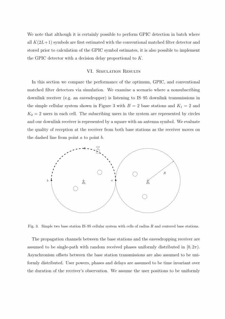
matched filter detectors via simulation. We examine a scenario where a nonsubscribing
downlink receiver (e.g. an eavesdropper) is listening to IS–95 downlink transmissions in
the simple cellular system shown in Figure 3 with B = 2 base stations and K1 = 2 and
K2 = 2 users in each cell. The subscribing users in the system are represented by circles
and our downlink receiver is represented by a square with an antenna symbol. We evaluate
the quality of reception at the receiver from both base stations as the receiver moves on
the dashed line from point a to point b.
R
ab
Fig. 3. Simple two base station IS–95 cellular system with cells of radius R and centered base stations.
The propagation channels between the base stations and the eavesdropping receiver are
assumed to be single-path with random received phases uniformly distributed in [0, 2π).
Asynchronism offsets between the base station transmissions are also assumed to be uni-
formly distributed. User powers, phases and delays are assumed to be time invariant over
the duration of the receiver’s observation. We assume the user positions to be uniformly
distributed within the cell. This assumption combined with IS–95 downlink power con-
trol implies that the user amplitudes observed at the eavesdropper are also random. The
distribution of the user amplitudes is derived in the Appendix under similar path-loss
modeling assumptions as the uplink study in [23], [24].
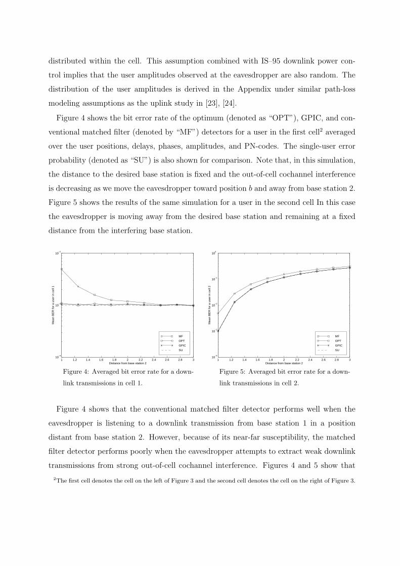
Figure 4 shows the bit error rate of the optimum (denoted as “OPT”), GPIC, and con-
ventional matched filter (denoted by “MF”) detectors for a user in the first cell2 averaged
over the user positions, delays, phases, amplitudes, and PN-codes. The single-user error
probability (denoted as “SU”) is also shown for comparison. Note that, in this simulation,
the distance to the desired base station is fixed and the out-of-cell cochannel interference
is decreasing as we move the eavesdropper toward position b and away from base station 2.
Figure 5 shows the results of the same simulation for a user in the second cell In this case
the eavesdropper is moving away from the desired base station and remaining at a fixed
distance from the interfering base station.
1 1.2 1.4 1.6 1.8 2 2.2 2.4 2.6 2.8 310
−4
10−3
10−2
Mea
n B
ER
for
a us
er in
cel
l 1
Distance from base station 2
MF
OPT
GPIC
SU
Figure 4: Averaged bit error rate for a down-
link transmissions in cell 1.
1 1.2 1.4 1.6 1.8 2 2.2 2.4 2.6 2.8 310
−4
10−3
10−2
10−1
100
Mea
n B
ER
for
a us
er in
cel
l 2
Distance from base station 2
MF
OPT
GPIC
SU
Figure 5: Averaged bit error rate for a down-
link transmissions in cell 2.
Figure 4 shows that the conventional matched filter detector performs well when the
eavesdropper is listening to a downlink transmission from base station 1 in a position
distant from base station 2. However, because of its near-far susceptibility, the matched
filter detector performs poorly when the eavesdropper attempts to extract weak downlink
transmissions from strong out-of-cell cochannel interference. Figures 4 and 5 show that
2The first cell denotes the cell on the left of Figure 3 and the second cell denotes the cell on the right of Figure 3.
the GPIC detector does not suffer from this problem and actually exhibits performance
indistinguishable from the optimum detector in these examples. These results suggest
that the GPIC detector may offer near-optimum eavesdropping performance over a wide
range of out-of-cell cochannel interference powers with the most benefit in severe out-of-cell
cochannel interference environments.
VII. On-Air Data
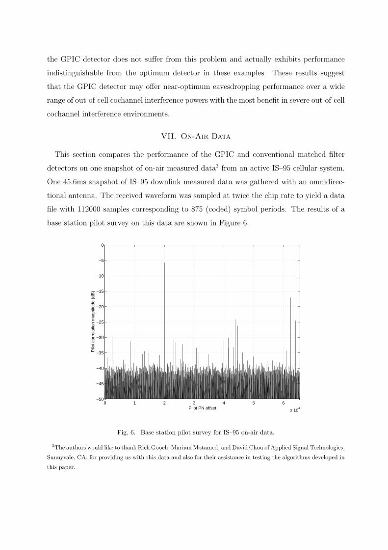
This section compares the performance of the GPIC and conventional matched filter
detectors on one snapshot of on-air measured data3 from an active IS–95 cellular system.
One 45.6ms snapshot of IS–95 downlink measured data was gathered with an omnidirec-
tional antenna. The received waveform was sampled at twice the chip rate to yield a data
file with 112000 samples corresponding to 875 (coded) symbol periods. The results of a
base station pilot survey on this data are shown in Figure 6.
0 1 2 3 4 5 6
x 104
−50
−45
−40
−35
−30
−25
−20
−15
−10
−5
0
Pilo
t cor
rela
tion
mag
nitu
de (
dB)
Pilot PN offset
Fig. 6. Base station pilot survey for IS–95 on-air data.
3The authors would like to thank Rich Gooch, MariamMotamed, and David Chou of Applied Signal Technologies,
Sunnyvale, CA, for providing us with this data and also for their assistance in testing the algorithms developed in
this paper.
Throughout this section, base station 1 denotes the base station with the strongest pilot
as seen at PN-offset 20000 in Figure 6. Base station 2 denotes the second strongest base
station at PN-offset 62500. The powers of each active Walsh channel at the output of
their respective matched filter detector, for both base station 1 and base station 2, are
given in Tables I and II. It can be seen that the power of the pilot (Walsh channel 0) from
base station 1 is approximately 11dB higher than the pilot from base station 2, hence our
receiver is positioned close to base station 1 and relatively distant from base station 2.
The remaining base stations seen in Figure 6 are ignored in the following development for
clarity.
Walsh Channel % of BS1 transmit power % of total received power
0 55.6 45.3
1 19.4 15.8
12 4.5 3.6
32 4.6 3.8
63 15.9 13.0
Total 100 81.4
TABLE I
Base station 1 active Walsh channels.
A. Conventional Matched Filter Detection
In this section we qualitatively examine the soft outputs of the conventional matched
filter detector for base stations 1 and 2. The matched filters are obtained by estimating
the impulse response of the combined propagation channel and pulse shaping filters via
pilot correlation and convolving this impulse response with the appropriate combined
Walsh and PN-codes for each active user in the system. Although Rake detection is
not used, the matched filter detector considered in this section automatically includes
coherent multipath combining since it incorporates the estimated impulse response of the
propagation channel.
Figure 7 shows a histogram of the matched filter outputs for the active Walsh channels
Walsh Channel % of BS2 transmit power % of total received power
0 54.5 3.2
1 18.5 1.1
20 17.0 1.0
32 5.2 0.3
34 4.8 0.3
Total 100 5.9
TABLE II
Base station 2 active Walsh channels.
of base station 1. Figure 7 clearly shows that the eye is open for all of the active channels
and implies that one could expect that these users’ decoded symbols would have very low
probability of error. In addition to the strong pilot channel at Walsh code 0, there is
a strong paging channel at Walsh code 1, a relatively weak sync channel at Walsh code
32, and two traffic channels of disparate power at Walsh codes 12 and 63. Qualitatively,
matched filter detection appears to be adequate for downlink reception of this base station.
Figure 8 shows a histogram of the matched filter outputs for the active Walsh channels
of base station 2. Figure 8 clearly shows that, unlike the transmissions from base station 1,
all of the channels from base station 2 are highly corrupted by interference (including out-
of-cell cochannel interference from base station 1, other base stations, and “unstructured”
noise sources). The eye is closed for all Walsh channels, implying that subsequent channel
decoding may be unreliable.
0
10
20
30
40
50
60
−0.6−0.4
−0.20
0.20.4
0.60.8
0
50
100
150
200
250
Walsh Channel
Matched Filter Output
pdf
Figure 7: Histograms of MF outputs by
Walsh channel for base station 1.
0
10
20
30
40
50
60
−0.5−0.4
−0.3−0.2
−0.10
0.10.2
0.30.4
0
20
40
60
80
Walsh Channel
Matched Filter Output
pdf
Figure 8: Histograms of MF outputs by
Walsh channel for base station 2.
B. GPIC Detection
In this section we qualitatively examine the soft outputs of the GPIC detector for base
stations 1 and 2. The matched filter outputs generated in the prior subsection are passed
through a hard decision device and then respread by the combined impulse response of the
appropriate Walsh codes, PN-codes, and estimated pulse-shaping and propagation channel
impulse responses. The waveforms are then scaled and rotated according to each user’s
estimated amplitude and phase.
Figure 9 shows the histogram of the matched filter outputs by Walsh channel of base
station 1 after subtraction of the estimated interference from base station 2. There is little
noticeable change from the results in Figure 7 since the out-of-cell cochannel interference
from base station 2 is very weak with respect to the transmission of base station 1 and
interference cancellation has little effect.
Figure 10 shows the histogram of the matched filter outputs by Walsh channel of base
station 2 after subtraction of the estimated interference from base station 1. The perfor-
mance improvement is significant with respect to the conventional matched filter results
in Figure 8. Channels 1 and 20 appear to be much cleaner and channels 32 and 34 are be-
ginning to exhibit troughs in the middle of their histograms indicating improved detection
quality. The pilot channel is also significantly cleaner.
0
10
20
30
40
50
60
−0.6−0.4
−0.20
0.20.4
0.60.8
0
50
100
150
200
Walsh Channel
Matched Filter Output
pdf
Figure 9: Histograms of GPIC outputs by
Walsh channel for base station 1.
0
10
20
30
40
50
60
−0.2−0.1
00.1
0.20.3
0
50
100
Walsh Channel
Matched Filter Output
pdf
Figure 10: Histograms of GPIC outputs by
Walsh channel for base station 2.
The results in this section agree with the simulation results in Section VI and suggest
that the GPIC detector may not offer much performance improvement when detecting
strong signals in the presence of weak out-of-cell cochannel interference. On the other
hand, comparison of Figures 8 and 10 show that significant performance improvements
are possible for a downlink receiver attempting to extract weak signals from strong out-
of-cell cochannel interference.
VIII. Conclusions
In this paper we investigated nonlinear multiuser detection for improving the perfor-
mance of IS–95 downlink reception. We used the orthogonality of the in-cell users of the
IS–95 downlink to develop a reduced complexity optimum detector with exponentially
lower complexity than the brute-force optimum detector under the assumption that the
propagation channels between the base stations and the receiver were single-path. Exam-
ination of the properties of the reduced complexity optimum detector led to the develop-
ment of the suboptimum, low-complexity GPIC detector. The GPIC detector does not
require any form of subspace tracking, matrix inversions, or exhaustive searches for global
maxima. Simulations and experiments with on-air IS–95 downlink data showed that the
GPIC detector offers the greatest performance improvements when detecting weak desired
signals in the presence of strong out-of-cell cochannel interference. Although this scenario
would be unusual for a subscribing user in an IS–95 cellular system, a nonsubscribing
user such as an eavesdropper may derive the greatest benefit from GPIC detection. Our
results also suggest that subscribing users that use GPIC detection can achieve an accept-
able quality of service with less base station transmit power which results in less induced
cochannel interference on out-of-cell users in the system.
Appendix: Received Power Distribution
In this appendix, we derive the received user power distribution for transmissions to users
in the mth cell observed by a receiver positioned at a deterministic distance d(m) ∈ (0,∞)
from the mth base station. We impose the following assumptions:
• Each base station is located in the center of its circular cell of radius R.
• Each user’s position is uniformly distributed in their cell and is independent of other
user positions. The kth user’s distance from base stationm is denoted by d(m,k) ∈ (0, R].
• Perfect power control is maintained between each base station and its users such that
the power received is identical for all users within the cell.
• The ratio of received to transmitted power obeys a simple path loss model 1/d2λ where d
is the distance separating the transmitter and receiver, and λ is the path loss exponent.
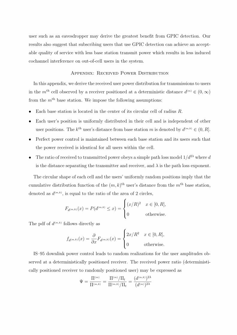
The circular shape of each cell and the users’ uniformly random positions imply that the
cumulative distribution function of the (m, k)th user’s distance from the mth base station,
denoted as d(m,k), is equal to the ratio of the area of 2 circles,
Fd(m,k)(x) = P (d(m,k) ≤ x) =
(x/R)2 x ∈ [0, R],
0 otherwise.
The pdf of d(m,k) follows directly as
fd(m,k)(x) =∂
∂xFd(m,k)(x) =
2x/R2 x ∈ [0, R],
0 otherwise.
IS–95 downlink power control leads to random realizations for the user amplitudes ob-
served at a deterministically positioned receiver. The received power ratio (deterministi-
cally positioned receiver to randomly positioned user) may be expressed as
Ψ =Π(m)
Π(m,k)=
Π(m)/Πt
Π(m,k)/Πt
=(d(m,k))2λ
(d(m))2λ
where Π(m), Π(m,k), and Πt denote the power of the mth base station observed at the eaves-
dropper, the power of the mth base station observed at the (m, k)th user, and the power
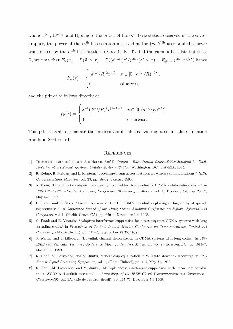
transmitted by the mth base station, respectively. To find the cumulative distribution of
Ψ, we note that FΨ(x) = P (Ψ ≤ x) = P ((d(m,k))2λ/(d(m))2λ ≤ x) = Fd(m,k)(d(m)x1/2λ) hence
FΨ(x) =
(d(m)/R)2x1/λ x ∈ [0, (d(m)/R)−2λ],
0 otherwise
and the pdf of Ψ follows directly as
fΨ(x) =
λ−1(d(m)/R)2x(1−λ)/λ x ∈ [0, (d(m)/R)−2λ],
0 otherwise.
This pdf is used to generate the random amplitude realizations used for the simulation
results in Section VI.
References
[1] Telecommunications Industry Association, Mobile Station – Base Station Compatibility Standard for Dual-