Page 1 | 74 Project Name: PROPOSED HVAC SYSTEM FOR MICROBIOLOGY LABORATORY AT CANCER CENTER Project Location: BGHMC COMPOUND, BAGUIO CITY TECHNICAL SPECIFICATIONS PREPARED BY: LENON S. BANA-E
Transcript
P a g e 1 | 74
Project Name: PROPOSED HVAC SYSTEM FOR MICROBIOLOGY LABORATORY AT CANCER CENTER
Project Location: BGHMC COMPOUND, BAGUIO CITY
TECHNICAL SPECIFICATIONS
PREPARED BY:
LENON S. BANA-E
P a g e 2 | 74
TABLE OF CONTENTS PART I GENERAL PROVISIONS PART II PRELIMINARY WORKS PART III EARTHWORKS AND SITE WORKS PART IV STRUCTURAL WORKS PART V CIVIL WORKS PART VI WATERPROOFING WORKS PART VII ARCHITECTURAL FINISHES PART VIII DOORS AND WINDOWS
P a g e 3 | 74
PART 1: GENERAL PROVISIONS AND CONDITIONS
1. GENERAL These specifications shall encompass all the work necessary for the building construction for the Project for Construction of “PROPOSED HVAC SYSTEM FOR MICROBIOLOGY LABORATORY AT CANCER CENTER” and as further defined herein. The work shall include furnishing all labor, materials, equipments, tools, facilities and transportation to complete the project in accordance the drawings and specifications.
The project site is located in BGHMC Compound, Baguio City, Philippines.
The work is implemented by the BGHMC.
Utilities for the temporary facilities shall be borne by the contractor such as, electricity, water
and means of communication during the implementation of the Project.
The Project Management Team shall act as the client’s representative for the building construction of the Project and provide construction supervisory services in an effort to ensure compliance by the Contractor with the contract document.
2. DEFINITIONS
The” Project” means the Project for the “PROPOSED HVAC SYSTEM FOR
MICROBIOLOGY LABORATORY AT CANCER CENTER” to be located at BGHMC Compound, Baguio City.
The “Client” means the Baguio General Hospital and Medical Center, and shall include any person or persons authorized to act in behalf BGHMC
The “PMT” means the Project Management Team which consist of engineers and architects hired by BGHMC to oversee the construction of the Project and shall include any person or persons authorized to act on behalf of the client.
The “BGHMC Project Manager”
means the person Designated by the Project Management Team as the over-all project manager who’s tasked to coordinated with the contractor’s technical personnel, end-users, suppliers and other persons involved in the project as the PMT representative
The “Work” comprises the completed construction required in the tender documents and includes all labor, services, materials and equipments incorporated in the construction.
The “Contractor” means the construction firm or company who has been awarded the contract by the client by due process of law and includes the Contractor’s personal representatives, successors and authorized assigns.
The “Supplier” means the person, persons or company where in the materials and equipments are awarded for the supply and installation if any.
3. CONTRACT DOCUMENTS Unless otherwise when clearly described, the drawings have the priority to the Specifications; the general notes in the drawings and subsequent design drawings shall prevail over the provisions described in the Specifications herein in case of discrepancies.
4. PERMITS AND LICENSES
The Contractor shall secure all the permits, except for the Building permission undertaken by the Client and licenses necessary for progression of work and negotiate and obtain permission with the related authorities.
5. WORKMANSHIP AND SAFETY
P a g e 4 | 74
The Contractor shall so conduct his operations as to work in harmony with the various trades involved and so conduct his work as not to endanger, damage, or interfere with or delay the operations of the Client and the Supplier during the Contractor carrying out all operations in connection with this contract.
Specially, the Contractor shall cooperate with the Supplier and coordinate his work with that of the latter with regard to the installation and testing of all the equipments.
The Contractor shall provide adequate temporary barracks and communal/sanitary facilities for his constituent or employee including health and insurances as defined under the National Labor Code and Safety.
6. PRESENCE OF THE PMT
Where so required in the Specifications, the Contractor shall carry out the work in the presence of the PMT representative.
The Contractor shall ask the PMT if his attendance to inspect required for any work, inspection is impossible or difficult after completion of the work, in the course of the work.
7. MEASUREMENT SYSTEM
The measurement system for the work shall be metric system.
8. APPLICABLE STANDARDS AND CODES The National Building Code of the Philippines and its implementing rules and regulations The Fire Code of the Philippines and Regulations Japanese Industrial Standards (JIS) American National Standards (ANSI) International Electrical Commission (IEC) National Structural Code of the Philippines (NSCP) International Organization for Standardization (ISO) American Society of Testing Materials (ASTM) National Fire Protection Association (NFPA) National Organization of Building Officials (NCBO) National Bureau of Standards (NBS) National Electrical Code of the Philippines (NEC) Sanitation Code of the Philippines (SCP) Plumbing Code of the Philippines (PCP) General Specifications for Building Construction Works
9. MATERIALS AND GOODS
Unless otherwise specified, all materials and goods shall be new and unused and all workmanship and materials shall meet and conform to the standards specified in the relevant sections of these Specifications. The Contractor shall carry out inspection of the materials to be used immediately upon the delivery to the site and shall promptly report the result of the inspection, any damage or substandard materials to the PMT. The PMT will judge whether they are satisfactory based on these Specifications. The materials and goods which are judged by the PMT unsatisfactory must not be used and be promptly removed from the site.
10. SAMPLES
The Contractor shall furnish for the approval of the PMT, with reasonable promptness all samples as specified in the relevant sections of these Specifications or as directed by the PMT. The work shall be in accordance with approved samples clearly marked must be kept on site at all times until final approval of the workmanship or fixing of the materials to which they apply.
11. APPROVAL OF MANUFACTURERS
The Contractor shall submit to the PMT for his approval a list of materials and equipments to be used and their manufacturer.
Where a name of trade firm or supplier is specified in the Contract Documents, no other products or services of other firms may be used. A substitution may be used subject to the PMT’s written approval where it is in all respects equal or superior to the original specification.
P a g e 5 | 74
12. SHOP DRAWINGS
The Contractor shall check and verify all site measurements and shall submit three (3) shop or setting out drawings and schedules with such promptness as to cause no delay in his own work or in that of any contractors. All of shop drawings shall be done by professional and shop draftsmen.
No Work shall commence before the approval of the PMT on such drawings and schedules.
The Contractor shall submit shop drawings for review by the PMT on a regular basis before required for construction or manufacturing.
The Contractor shall inform the PMT of any discrepancies or contradictions found in the Contract Documents, prepare proposals for resolving the problem.
Prior to every shop drawing, the Contractor shall submit the General Shop Drawings,1:50 scale
plans and interior elevations and ceiling reflected plans drawn all visible things including electrical, plumbing, air-conditioning and ventilation works.
All shop drawings shall be reduced to A3 size bond paper and be submitted to the PMT upon completion of the work.
Shop drawings are subjected to be drawn computer aided. Data of working drawings will be allowed to be used for reference of them.
13. TEST AND INSPECTIONS
Each part of the Work shall be inspected and tested to confirm that the workmanship is satisfactory for the requirements specified in the design documents at each stage of the work or when so directed by the PMT.
The Contractor shall consult with the PMT as to the program of the inspection and test and shall ask the PMT’s attendance to the inspection and test. Upon the practical completion of the work, the Contractor shall, in the presence of the PMT, inspect and test the whole of the works to confirm that all the work done is in conformity with the requirements specified in the design documents.
Any defects found during this inspection shall be repaired to the satisfaction of the PMT before the agreed repairing period is over.
All concrete test cylinders, water and reinforcing bars shall be tested at an authorized testing laboratory approved by the PMT and tested with the presence of the PMT representative/s.
All manufacturers’ instructions must be strictly observed and adhered to with respect to workmanship, handling and conditions at time of installation or application.
The Contractor shall record the results of each inspection and test and submit them for the PMT’s approval without undue delay.
14. RECORDS, REPORTS AND CONFIRMATION
The Contractor shall take photographs of the Site before starting the construction and keep detailed records as specified below and as directed by the PMT and submit diurnally to the PMT for his approval. Photographs shall be taken by digital camera and be submitted by data too.
Daily Weather Conditions
Progress of Work including photographs showing the progress Delivery of materials and equipment Site labor time sheets Details of all visitors to the site
P a g e 6 | 74
The Contractor shall always be requested to confirm and inspect whole process of the work and shall report that process and inspection record in writing before requesting the inspection by the PMT without failure. No exception shall be accepted.
The Contractor shall submit from time to time to the PMT reports, notices and other documents as specified in the Specifications and as directed by the PMT such as,
Notification of commencement and information of works
Manufacturer’s List General Work Schedule Monthly Progress Reports Work Diary Detailed Work Schedule Shop Drawings and Construction Details Test Results
Daily Activities Report (Submitted Weekly and signed by Contractor and Client representative)
15. CONSTRUCTION AND INSURANCES
The Contractor shall at its expense buy and maintain the following insurance effective during the performance of the Contract such as, Erection All Risk Insurance, Third party Liability Insurance and Workers’ Compensation.
15. REPORTS AND SUBMITTALS
The Contractor shall submit to the PMT their daily activity reports every last working day of the week. Use format shown below.
P a g e 7 | 74
* Daily Activity Report Format
P a g e 8 | 74
QUALITY REQUIREMENTS: A. This Section specifies administrative and procedural requirements for quality control services that are to be performed by the Contractor and his subcontractors for all aspects of project coordination, administration, monitoring and execution. This procedure requires that the Contractor establish an independent internal team staffed apart from the Contractors administrative team whose sole responsibility is to provide quality assurance monitoring and quality control reporting and implementation of specified standards. This independent team shall act as a separate audit and shall report to the Project Manager and Contractor’s administrative staff on a weekly basis covering all aspects of work or preparation for work not yet began and implementation of repair works and monitoring of repair.
P a g e 9 | 74
PART II: PRELIMINARY WORKS
A. GENERAL
This section covers the requirements for providing all the temporary work at the Project Site. The work shall include all labor, materials, equipment, tools and transportation necessary to complete the temporary work specified herein. B. TEMPORARY CONSTRUCTION AND FACILITIES The Contractor shall provide and maintain all temporary construction and facilities necessary to complete the Work as shown on the drawings and as specified herein. All temporary installation used for the work shall be removed after completion of the Work. C. BENCH MARK The Contractor shall relate his site level to the nearest official Benchmark established by the Municipal
Government. Should this prove impractical then the Contractor shall refer to site datum level benchmark to be established inside the site boundary in the presence of the PMT, where it shall rigidly set in position and where it can remain undisturbed during the whole progress of the Work and be provided with adequate protection. It shall be adequately maintained and inspected at regular intervals. D. PREVENTION OF ACCIDENTS It is a standard procedure for the Contractor to maintain proper safety inside and around the premises of the job site for his employees, constituents and pedestrians. Adequate gadget for fire and other ways and means shall be readily available at all times in case of emergency and disaster.
P a g e 10 | 74
PART III: EARTHWORKS WORKS AND SITE WORKS A. GENERAL This section covers the requirements for performing all filling works, excavation required for the construction of footing and foundations, the subsequent backfilling of excavated materials to the designated grade, the disposal of all excavated materials not required for backfill, foundation sub grade works, the preparation of hard core for pavements and other related items necessary to complete the Work indicated on the drawings and specified herein. Items of works shall include but not limited to the following
a. Excavation b. Removal of excess ground water c. Fills and backfill
d. Disposal of excess excavated materials e. Preparation of hard core f. Foundation sub-grade work g. Termite control
B. SAFETY MEASURE The Contractor shall survey the existing condition of the site and the adjacent areas noting the subsurface condition and water table level, and shall take proper safety measure not to adversely affect the site condition. C. FILLS
PREPARATION OF SITE Grass, stumps, masonry, rubbish, weeds and other unsuitable materials shall be removed from the construction site. In case of low lying area, mud shall be removed.
FILLING MATERIALS Sand, earth such as clay loam and laterite, or their combination without rubbish, chemicals weeds and other unsuitable materials can be used for fills subject to the PMT’s approval.
PROCEDURE a. If earth is used, every layer of 30 cm in depth shall be compacted by roller weighing not
less than 3 tons. In case of wet soil tamper shall be used for compaction. b. If sand is used, every layer of 30 cm in depth shall be compacted by rollers weighing not
less than 3 tons, using water. In case of low lying area where sand could be wash away, clay embankment shall be used to confine sand.
COMPACTION Compacted layer of fill material shall have an in-place density not less than 96 % of maximum density.
LEVEL The surface of the finished fill shall be flat and level and shall have correct elevation as specified. After finishing fill, level and elevation of the fill shall be inspected and shall be obtained PMT’s approval. D. EXCAVATION Prior to the start of excavation, the Contractor shall survey the filled site level and verify the designated datum level in the presence of the PMT’s representative/s. All excavation shall be carried out with and adequate angle of repose to avoid the Collapse of ground material. The slope shall be properly protected to the satisfaction of the PMT during the excavation work.
P a g e 11 | 74
During the excavation work, any settlement or movement of the site or adjacent land and any changes in bearing capacity or water table level shall be recorded and be informed to the PMT as require. If any adverse effects are found as the result of such measurement, the Contractor shall report it to the PMT and shall take proper safety measures without delay. In the event the excavation work encounters unexpected obstacles, the Contractor shall keep the PMT informed and shall take all possible steps to remove such obstacles after checking to see that is safe to do so or suggest, for the PMT’s approval, any remedial action required to prevent delay in the progress of the work. The Contractor shall excavate to the depths and extend indicated on the drawings and allow additional space as required for construction operations and inspections of foundation. Bottoms of excavations shall be accurately finished level to the grades shown on the drawings or agreed on site. Excavations for footings carried below the specified grades shall be backfilled to grade at no extra charge. Any disturbed portions shall be compacted to equal or exceed the bearing capacity
of surrounding areas. When excavation work reaches the designated levels the PMT’s approval must be obtained before proceeding with the Work. If a suitable bearing capacity is not encountered in the subsoil at the depth indicated on the drawings for foundations, the Contractor shall immediately notify the PMT.
E. REMOVAL OF EXCESS GROUND WATER The Contractor shall keep the whole of the excavations free from water arising from rain, drains, flood,
springs or any other cause by pumping, bailing or drainage. Care shall be taken not to disturb subsoil conditions while providing drainage ditches or pits. The Contractor shall keep the site clear of water at all times until 30 days after completion of the
foundation work. F. BACKFILL All soil used for backfilling shall be approve by the PMT.
No backfilling shall be commenced without the prior approval of the PMT. While backfilling, the soil shall be evenly backfilled and have an optimum water content ratio. Every layer or 30 cm in depth or less shall be compacted enough by tamper, roller or hammer. Compacted layer of fill material shall be tested for every 30 cm in depth and must have an in-place density not less than 96 % of maximum density.
Any portion of soil which cannot be compacted by rollers after backfilling shall be well compacted with
a hammer or the like. During backfilling work, care shall be exercised not to damage the structure. Where residual settlement can be reasonably expected after backfilling, extra fill shall be provided as
instructed by the PMT.
G. DISPOSAL OF EXCESS EXCAVATION MATERIAL Excavated material not required for backfill shall be disposed of by filling site areas, filling in building areas or otherwise as directed. All remaining material shall be evenly spread within the site under the PMT’s instructions. It must be the Contractor’s responsibility to secure permits for the disposal locations of excess material excavated.
H. PREPARATION OF HARDCORE
P a g e 12 | 74
Crushed stones to be used for hard-core shall be of a suitable mixture of grades between 30mm mesh and 50 mm mesh conforming to JIS A 5001 “Crushed Stone of Road Construction.” Materials for blinding and making up levels shall be fine crushed stones. Crushed stones shall be laid on the excavated surface in a thickness as indicated on the drawings and be thoroughly rammed.
I. FOUNDATION SUBGRADE WORK
RUBBLE SUB-GRADE TYPE THICKNESS LOCATION
Rubble or crushed stone 150 mm below on grade Below spread footing
Sand 60 mm below grade beam
Rubble and gravel shall be well compacted. Rubble sub grade below slabs on grade shall be compacted enough by load roller, vibration roller or other proper tools. Care shall be taken to avoid unfavorable effects on the ground below sub grade work by compaction. Provide P.E. sheets on top of compacted fill for Slab on fill prior to concrete pouring to serve as moisture and thermal protection. J. LEAN CONCRETE
Unless otherwise indicated in Bill of Quantities or Plans, the specifications for lean concrete shall be the following: Compressive strength of concrete: F’c = 14 MPa (28 days’ cylinder test) Proportion : 1:3:6 Thickness : 50 mm Where used : As indicated on the drawings
For systems and procedure for the Lean Concrete, Chapter IV of this specification shall also apply.
P a g e 13 | 74
PART IV: STRUCTURAL WORKS
CHAPTER I: CONCRETE WORKS
A. GENERAL
This section covers the requirements for performing all the work required to construct reinforced concrete work at the Clients’ project site. The Provision of this specification shall govern wherever applicable except as otherwise provided in the design drawings. In case of conflicting with requirements, the design drawings shall govern.
B. SUBMITTALS
1. Source of materials 2. Material data 3. Concrete Compressive Test results of the Concrete Trial Mix
4. Shop drawing of the layout as per actual dimensions for PMT’s approval. 5. Inspection Request. Inspection request must be submitted at least 2 days before concrete pouring
scheduled time. 6. Concrete Compressive Test results of the Concrete actually placed 7. Other Test Results required by PMT
B. MATERIALS 1. CEMENT The Cement shall be equal to ASTM C 150 Type 1 or Portland Cement Type 1.
The brand of cement to be used for concrete work shall be approved by the PMT and must not be changed during the progress of work unless otherwise approved by the PMT.
The amount of free alkali content shall not exceed the value of 0.6 percent by weight. The cement shall be used in the order of delivery. No cement shall be used which has been moistened or which has been delivered to the site more than 1 month prior to its proposed use, unless otherwise approved by the PMT. 2. AGGREGATES The aggregates shall be well graded, clean, hard particle of sand, gravel or crushed stone and conform to ASTM C33 “Standard Specification for Concrete Aggregates”. The aggregates shall have strength higher than that of the cement paste when hardened in concrete. The source of aggregates supply shall not be changed during the course of the work.
a. Coarse Aggregates: Coarse aggregates shall consist of gravel, crushed stone or a combination thereof and shall be clean, hard, durable uncoated particles free from salt, organic matter and clay more than 0.25% by weight. Course aggregates shall be well graded between the following limit sizes and conform to the sieve analysis requirements.
b. Fine Aggregates: Fine aggregates shall be river sand free from salt and organic matter, and
shall be composed of clean, hard, strong and durable spherical or cubical particles, Clay shall not be contained more than 1%.
c. Maximum Size of Aggregates: The maximum size of aggregates shall not exceed 1/5 of the
narrowest part of pouring form, ¾ of the spacing between each reinforcements or each bundle of reinforcement or 25 mm.
3. WATER Water to be used in mixing concrete shall be clean and free from matters such as salt, oil, acid, alkaline, organic matter or other substances, in a quantity which will be harmful to concrete or reinforcement. 4. ADMIXTURES
P a g e 14 | 74
Proper mixtures may be used in concrete, unless it adversely affects the quality of concrete. Admixture to be used in concrete, when required, shall be subject to prior approval by the PMT and shall conform to the appropriate specifications listed below:
1. Air Entraining Admixtures: 2. ASTM C260 “Specification for Air – Entraining Admixture for Concrete” 3. Water-reducing, retarding, and accelerating admixtures: 4. ASTM C494 “Specifications for Chemical Admixture” 5. Other rational specifications with prior approval by the PMT.
Admixture containing chloride ions shall not be used in concrete. 5. REINFORCEMENT In general, all Reinforcement steel bars shall be in conformance to “Chapter IV” of this Part of specification.
6. STORAGE OF MATERIALS
a. Cement shall be stored in a proper manner above the ground not less than 30 cm and in a
well ventilated water-tight shed to prevent deterioration.
b. Cement bags shall not be piled up to the heights exceeding 10 bags and shall be kept neat for easy inspection.
c. Coarse and fine aggregates shall be stored separately on clean and hard surfaces, and mutual mixing or contamination by organic material shall be prevented.
d. Care shall be taken to avoid segregation of large and small particles of coarse aggregates in delivery or stockpiling. Stockpiles of aggregates shall be as low as possible and be allowed to drain.
e. Any materials that has deteriorated or has been contaminated shall not be used for concrete. C. MIXING OF CONCRETE
1. GENERAL
a. All concrete shall be so mixed that the required strength, workability, uniformity and durability will be obtained.
b. Prior to the commencement of the work, the contractor shall determine concrete mix proportions and submit a mixing plan to the PMT prior for his approval.
c. Standard design strength, dry unit volume and slump of concrete shall be as specified on the
drawings. 2. PROPORTIONING
a. For general reinforced concrete work with specified compression strength less than 240
kg/cm², the quantity of cement used must not be less than 280kg/cm³ (7bags/m³) but not more than 380kg/cm³(9.5bags/m³).
b. When the selection of concrete proportioning is done by laboratory trial by batches, the strength test shall be made in accordance with the “Methods for Compressive Strength of Cylindrical Concrete Specimens” (ASTM C39) and “Methods of Making and Curing Test Specimen in the Laboratory” (ASTM C192). The highest water-cement ratio used in concrete for structural work shall be based on readings from the curve of relationship between the ratio of water-cement and the compressive stress in order to obtain the stipulated compressive stress except when there are other necessities requiring the reduction of water-cement ratio, or the increasing of compressive strength.
P a g e 15 | 74
c. If the appropriate data from laboratory trial batches or field test are not readily available. The maximum permissible water-cement ratio which is given in the table below may be used for concrete proportioning. This table shall be used only for concrete which uses cement in accordance with the standard of Portland Cements in accordance with ASTM C150.
LIMITS OF HIGHEST WATER-CEMENT RATIO IN CONCRETE
Required Compressive Highest Water-Cement
F’c Ratio by Weight Air entrained concrete
180 0.65 0.54
210 0.58 0.46
240 0.51 0.40
280 0.44 0.35
310 0.38
3. MEASUREMENT OF MATERIALS
a. The Contractor shall submit a measurement plan indicating method and equipment of measurement to the PMT for his approval.
b. Each material shall be separately measured on a batch method by weight. c. Cement shall be measured by weight or by number of bags. d. Workability aids shall be accurately measured in diluted solution.
4. MIXING
a. Concrete shall be mixed in a power batch mixer of an approved type unless hand mixing is approved by the PMT. Concrete mixer shall not rotate faster than 30 times per minute.
b. The batch mixer shall be thoroughly cleaned after each round by running for at least 15 minutes with medium and coarse aggregate and a lavish supply of water. The water used for cleaning shall be kept away from the formwork or placed concrete.
c. All the materials for each batch shall be put into the drum at one time. The volume of concrete
mixed per batch shall not exceed the mixer’s nominal capacity specified by the manufacturer.
d. Mixing shall be continued for a period of not less than one and half minutes after all materials have been put in the drum and until there is a uniform distribution of materials and the mass is uniform in color. The mixing time of batch shall be kept uniform throughout the work. Standard mixing shall be according to the table below.
STANDARD CONCRETE MIXING TIME
Capacity (m³) Mixing Time
Minimum Maximum
Less than 2 1 min. 45 sec. 5 min. 15 sec
Less than 3 2 min. 30 sec. 7 min. 30 sec.
Less than 4 2 min. 45 sec. 8 min 45 sec.
Less than 5 3 min. 9 min.
e. Each batch mixer shall be thoroughly emptied and cleaned before for the next batch is put into
the drum. f. Concrete which has set shall not be used nor re tempered, but shall be discarded. g. Before each run of a cleaned batch mixer a preliminary mix of sand and cement shall be run
then discarded. 4. SLUMP
a. A consistency of concrete shall be such that the mixture will work readily into the corners and
angles of the forms and around reinforcement with the method of placing employed on the work, but without permitting the materials to segregate or excessive free water to collect on the surface.
P a g e 16 | 74
b. The slump of concrete shall be the minimum that is practicable. When vibrators are used to consolidate concrete, the slump shall not exceed 4-inches (10cm); otherwise, the slump shall not exceed 5-inches (12cm). Addition of water during hot weather to maintain the same slump must be compensated by adding more cement to retain the water-cement ratio.
5. TRANSPORTATION OF CONCRETE
a. The concrete shall be transported to from the place of final deposit as rapidly as practical, by means which will prevent segregation, consolidation, leakage or drying out.
b. If segregation is found in concrete during transportation, such concrete shall be mixed again to
obtain a uniform distribution of materials. c. When a bucket with an opening at the bottom is used for transportation, such concrete such
that the opening is at the center of the bottom, easily operated and allows no leakage.
d. Pouring bucket shall be such a type to deposit concrete uniformly. e. The delivery distance by barrows or Lorries shall not exceed 60 m, and a smooth road for such
transportation shall be provided to prevent segregation. f. Chutes shall be metal or metal-lined and shall have a slope not exceeding 1 vertical to 2
horizontal and not less than 1 vertical to 3 horizontal. Chutes more than mom long and chute not meeting the slope requirements may be used provided they discharge into a hopper before distribution.
g. All equipment used for transporting the concrete shall be thoroughly cleaned at the end of each operation or work day.
6. PLACING OF CONCRETE
a. Prior to the commencement of placing, a placing plan indicating locations, sequence and
amount of concrete to be placed shall be submitted to the PMT for approval.
b. Concrete shall not be placed before all forms, reinforcement, embedded items and the surfaces upon which the concrete is to be placed have been approved by the PMT.
c. Before placing concrete, all rubbish, standing water and loose material shall be removed. The
face of the formwork in concrete with the concrete shall be sprayed with clean water immediately prior to concreting.
d. Before placing concrete in sub grade, semi porous sub grade shall be sufficiently sprinkled with
fresh water in order to eliminate suction, and porous sub grade shall be sealed in an approved manner.
e. Slabs on grade shall have a base of rubble compacted and rolled to a dense condition.
7. PLACING
a. Concrete shall be placed within 30 minutes after discharge from the mixer but in no case more
than 60 minutes from the time water was added.
b. Indiscriminate addition of water to increase slump shall be prohibited. Concrete shall be spaded and worked by hand and vibrated to assure close contact with all surfaces of forms and reinforcements and leveled off at proper grade to receive finish. No concrete that has partially hardened or been contaminated by foreign materials shall be deposited in the work, nor shall re-tampered concrete be used.
c. All concrete shall be placed continuously, or in layers not over one-half meter deep, upon clean, well thawed, damp surface free from water, and never upon soft mud nor dry porous earth.
P a g e 17 | 74
d. When concrete is deposited in layers, concrete to be superimposed on the preceding layer shall be placed within two hours after previous concrete has been placed.
e. Concrete shall not be permitted to drop freely over two meters in un exposed work nor over one meter in exposed work to avoid segregation. Where greater drops are required, tremies or other approved means shall be used. Tremie discharge shall be controlled so that concrete may be compacted effectively into horizontal layers not over 30 cm thick.
f. When concrete is conveyed by chute, a continuous concrete flow shall be maintained. Discharge chute end shall be provided with baffle plate to prevent segregation.
g. If chute discharge end height is over two meters, a spout shall be used and its lower end maintained as near deposit surface as practicable.
h. When pouring is intermittent, a discharge chute shall be thoroughly cleaned before and after each run. Waste material and flushing water shall be discharged outside forms.
i. Concreting for such vertical portions as columns and walls shall be made up to the bottom of
beams, placing of concrete in supported elements shall not be started until the concrete previously placed in columns and walls is no longer plastic and has been in place at least two hours.
j. No concrete shall be placed during rain, and any freshly placed concrete shall be protected from rainfall.
k. The temperature of the concrete shall not be so high as to cause difficulty from loss of slump, flash set, or cold joints and should not exceed 32°C, pre cautionary measures approved by the PMT shall be put into effect. When the temperature of the steel is greater than 49°C, steel forms and reinforcements shall be sprayed with water just prior to placing the concrete.
l. Before placing fresh concrete on or against concrete that has set, concrete shall be thoroughly cleaned so as to expose the coarse aggregate. Forms shall be retightened and all surfaces moistened.
8. CONSOLIDATION
a. All concrete shall be thoroughly consolidated by vibration, spading, rodding, forking or other suitable means during placement, so that the concrete is thoroughly worked around the reinforcement, around embedded items, and into corners of forms, eliminating all air or stone pockets which may cause honey combing, pitting, or planes of weakness.
b. Internal vibrators shall have a minimum frequency of 8,000 vibrations per minute and sufficient amplitude to consolidate concrete effectively. They shall be operated by competent workmen.
c. Use of vibrators to transport concrete within forms shall not be allowed. Vibrators shall be inserted and withdrawn at points approximately 50cm apart.
d. At each insertion, the duration shall be sufficient to consolidate the concrete but not sufficient to cause segregation, generally from 5 to 15 seconds.
e. A spare working vibrator shall be kept on the job site during all concrete placing operations.
f. Where the concrete is to have an as-cast finish, full surface of mortar shall be brought against the form by the vibrating process, supplemented if necessary by spreading to work the coarse aggregate back from the formed surface.
g. Concrete in slabs shall be thoroughly consolidated. Internal vibration shall be used in beams and girders. Consolidation of slabs shall be obtained with vibrating screeds, roller pipe screeds, and internal vibrators or approved means.
9. CURING OF CONCRETE
a. GENERAL:
P a g e 18 | 74
Concrete shall be protected against moisture loss, excessively hot temperature, rapid temperature change, mechanical injury from rain or flowing water for the period of the first at least 7 days after placement. Curing procedure shall conform to ACI 308 “Recommended Practice for Curing Concrete” and ACI 305 “Hot condition at temperature above 10 C but not over 32 C.
The Contractor shall prepare a curing plan taking the weather conditions on site into account and submit it to the PMT for his approval.
b. CURING MATERIAL
Waterproof paper: Non-staining reinforced waterproof curing paper, conforming to ASTM C171, or approved equivalent. Impervious sheeting: ASTM C171 or approved equal, type optional, except that polyethylene
sheeting shall be 0.1 mm minimum thickness, white opaque. In areas of high winds the impervious sheeting shall not be used. Burlap: Clothe made of jute or kenaf shall conform to AASHTO M182 or approved equivalent and shall weight a minimum 0.29 kg/m2. Liquid membrane forming compound: ASTM C309, Type 1 or approved equal. When non-pig mental compound is used, it shall contain a fugitive dye.
c. PRESERVATION OF MOISTURE
For concrete surfaces not in contact with forms, one of the following procedures shall be applied immediately after completion of placement and finishing:
• Ponding or continuous sprinkling
• Application of absorptive mats or fabric kept continuously wet
• Application of sand kept continuously wet
• Continuous application of steam (not exceeding 65 C) or mist pray
• Application of waterproof sheet materials, conforming to ASTM C171 or approved equivalent
• Application of other moisture-retaining covering as approved
• Application of a curing compound conforming to ASTM C309 or approved equivalent Moisture loss from surfaces placed against wooden forms or metal forms exposed to heating by the sun shall be minimized by keeping the forms wet until they can be safely removed. After form removal, the concrete shall be cured for at least 7 days by one of the methods above.
d. TEMPERATURE, WIND AND HUMIDITY
Hot weather: When necessary, provision for windbreaks, shading, and fog spraying sprinkling, ponding, or wet covering with a light colored material shall be made in advance of placement, and such protective measures shall be taken as quickly as concrete hardening and finishing operations will allow. Rate if temperature change: Changes in temperature of the air immediately adjacent to the concrete during and immediately following the curing period shall be kept as uniform as possible and shall not exceed 3 C in any 1 hour or 28 C in any 24 hours’ period.
10. PROTECTION FROM MECHANICAL INJURY
During the curing period, the concrete shall be protected from damaging mechanical disturbances, such as load stresses, heavy shock, and excessive vibration. All finished concrete surfaces shall be protected from damage by construction equipment, materials or methods, by
P a g e 19 | 74
application of curing procedures, and by rain or running water. Self-supporting structures shall not be loaded in such a way as to overstress the concrete.
D. FAIR-FACED CONCRETE
GENERAL
1. This subsection covers fair-faced concrete which will be exposed to view as indicated on the drawings.
2. Prior to the construction, the Contractor shall prepare a ‘construction joint’ program, formwork drawings, clean out details and proposal for remedial and patching methods and submit them to the PMT for his approval.
3. During the whole of the construction, the work shall be properly observed. At least one observer shall be provided for each stage of the work i.e. formwork construction, reinforcement bar arrangement,
concrete mixing pouring and vibration, curing and striking.
REMEDY AND PATCHING
1. Remedy and Patching of fair-faced concrete shall be minimized in frequency, and if unavoidable, be carried out carefully according to the approved program (see 9.1.b) only with the consent of the PMT.
2. Whereas-cast finishes are specified, the total patched area shall not exceed 0.2 m2 in each 100 m2 of as-cast surface. This is in addition to form tie patches, if the drawings permit ties to fall within as-cast areas.
3. Any patches in as-cast fair-faced concrete shall closely match the color and texture of surrounding surfaces.
The mix formula for patching mortar shall be determined by trial to obtain a good color match with the concrete when both patch and concrete are cured and dry. After initial set, surfaces of patches shall be dressed manually to obtain the same texture as surrounding surfaces.
4. Patches in fair-faced concrete surfaces shall be cured for 7 days. Patches shall be protected from premature drying to the same extent as the body of the concrete.
E. TESTS AND INSPECTIONS
GENERAL
1. This subsection describes the item, frequency and methods of tests and inspections. 2. Concrete materials and operations will be tested and inspected as the work progresses. The PMT reserves the rights to order tests on any materials to be used in the mixing of concrete and reinforced concrete, at any time, to examine whether such materials and concrete comply with the specified quality or not. All expenses for tests and inspections shall be borne by the Contractor.
3. The Contractor shall test and inspect the aggregates, cement, any other additives and the concrete mix before and during construction as specified herein. The results of all such tests and inspections shall be satisfactory to the PMT.
4. All tests shall be done by a testing laboratory provided by the Contractor and approved by the PMT, and done according to the standards of the Science Department, Ministry of Industry, or the ASTM methods and procedures. Testing laboratory may supervise the mix and delivery of all concrete.
5. To facilitate testing and inspection, the Contractor shall:
a. Furnish any necessary labor and convenience to assist the testing laboratory in obtaining and handling samples at the project site or other sources of materials.
P a g e 20 | 74
b. Advise the testing laboratory sufficiently in advance of operations to allow for completion of quality tests and for the assignment of personnel. c. Provide and maintain for the sole use of the testing laboratory adequate facilities of safe storage and proper curing of concrete test specimens at the project site. d. The Contractor shall keep a record of all tests during the construction and for at least two years after the whole construction has been completed.
TEST OF MATERIALS
Materials used shall be tested in accordance with the table TABLE 5.10.1 Material Test Method
Material Frequency Number of Test Method Specimens (ASTM)
Cement Minimum once for 1 lot= 100 at Air content of C185 Each different type, minimum Mortar Brand and cement ----------------------------- Work 1 specimen Chemical C114 Per lot Analysis ----------------------------- False Set C451
Aggregates Minimum once for 1 lot=300m3 Grading C136 Each source and Minimum 2 ----------------------------- Location Washing C117 Specimen per ----------------------------- Lot Unit Weight C29 ----------------------------- Organic C40, Impurities C87 ----------------------------- Clay lump C142 ----------------------------- Soundness C83 ----------------------------- Abrasion C131, C535
Water Minimum once for Minimum once Chemical As per Each source of analysis JASS Supply 5T-301
Reinforcing Minimum one rod 1 lot=50 ton Mechanical A370 Bars for each source of minimum 3 test (tension Supply per batch rods per lot bending)
Per size
Remark: Standards for the method of test indicated herein may be replaced by appropriate JIS Standards with prior approval of the PMT.
SAMPLES
1. Samples from stock on the site shall be taken by the Contractor as indicated by, and in the presence of the PMT.
a. Cement: Sampled cement shall be tested by the approved testing laboratory. Certified copies of laboratory test reports shall be furnished for each lot of cement and shall include all test data, results and certification that the sampling and testing procedures are in conformance with the specifications.
P a g e 21 | 74
No cement shall be used until its test results are satisfactory to the PMT. Cement that has been stored for more than four months after being tested shall be retest before use. b. Aggregates: Aggregate sampling shall conform to ASTM D75. Aggregates shall be sampled and tested by the testing laboratory. No aggregate shall be used until its test results are satisfactory to the PMT.
2. Samples of fresh concrete shall be obtained different batches of concrete on a random basis in accordance with ASTM C172, and shall be transported to a placed in the site where tests can be made and cylinders stored without being disturbed for the first 24 hours.
TRIAL MIX TESTS OF FRESH CONCRETE
1. Trial mix test shall be conducted at least once for each mix proportion in accordance with table 5.10.2 Tests shall be carried out in the presence of the PMT more than 28 days before concrete placing.
Table 5.10.2 Trial Mix Test
Items Test Method
Workability Slump ASTM C143 Air content ASTM C231 Strength Compression ASTM C39 Weight Unit weight ASTM C138
Note: Other rational standards such as JIS will be accepted instead only with prior approval of the PMT.
2. Compression strength tests shall be carried for each three specimens at 7 days and 28 days.
FRESH CONCRETE INSPECTIONS
1. Inspections must be carried out closely adjacent to the site of pouring in accordance with table 5.10.3 Table 5.10.3 Fresh Concrete Inspections
Items Minimum number of Test Method Specimens
Fresh 1 lot= 10 m3 Slump ASTM C143 Concrete minimum 1 specimen Per lot Air content ASTM C231 1 lot= 10 m3 Compressive ASTM C39 Minimum 3 specimens strength per lot on a random basis
per concrete pouring
Note: Other rational standards such as JIS will be accepted instead only with prior approval of the PMT.
2. Where any test result proves unacceptable to the PMT, the Contractor shall be discarded the whole of the concrete batch.
3. Slump tests and air contents tests shall always be made from the same batch from which compressive strength tests are made.
4. The standard age of concrete for strength test shall be 7 days and 28 days. For strength test at 7 days the Contractor shall provide three test specimens for each test taken in the presence of the PMT less than once for each 10 m3 or fraction thereof nor less than once a day, or less than once for each 500 m2 of floor area of each class of concrete placed. Samples shall be secured in accordance with ASTM C172 or approved equivalent standards. Test specimens shall be made a cured in accordance with ASTM C31 or approved equivalent standards.
P a g e 22 | 74
5. Test specimens for strength tests shall be evaluated for each class of concrete specified in conformance with ACI 318, Chapter: 4 “Concrete Quality” or approved equivalent standards
6. When the results of the strength test of the specimens indicate deficiency in specification requirements or where there is other evidence that the quality of the concrete is below specification requirements, core boring tests shall be made in conformance with ASTM C42 or approved equivalent standards, at the Contractor’s expense. If deficiency discovered, the Contractor shall ask the PMT for the treatment, and shall yield to the instruction of the PMT.
CONTINUOUS INSPECTION
1. In concrete work, the PMT will inspect the works in every stage and every step of the work.
2. The PMT will supervise and ascertain that the concrete work is in accordance with the plans and specifications, and shall keep records which shall be submitted by the Contractor and cover the
followings: a. Quantity and proportion of materials for the mixing of concrete b. Placing and curing of concrete c. Reinforcement d. Formwork and shoring e. Placement of important load on the floor during the construction f. general progress of work
3. When air temperature rises above 35 deg Celcius, a complete record shall be kept of the temperature of concrete and the concrete shall be protected during placing and curing operations.
G. PAYMENT METHODOLOGY
The work under this item shall be measured by the volume of concrete actually installed as per planned. Excess of the quantity due to Contractors corrections such as increase of dimensions shall not be considered in the pay item. For a work to be considered finished, the concrete must have undergone all the necessary work from preparation, curing and satisfactory test results. The quantities to be paid shall only include those of which completely finished, inspected and acceptable to the PMT. In cases that the concrete does not pass the required compression test, it is the responsibility of the Contractor to perform any of the following without the expense of the owner. 1. Removal of Concrete installed 2. Retrofitting up to PMT’s satisfaction.
P a g e 23 | 74
CHAPTER II: PRECAST CONCRETE
GENERAL REQUIREMENTS
1. Structural pre cast concrete shall be manufactured in fabrication shop or site fabrication shop.
2. Concrete, reinforcement and other materials used in structural precast concrete members are uniform in color and appearance.
3. Following submittals shall be prepared by the Contractor and submitted to the PMT for his approval.
a. Shop drawing showing layout, unit locations, fabrications details, unit identification marks, reinforcement, connection details, support items dimensions, openings and relationship with
adjacent materials. b. Product, data showing standard component configurations, deflections, cambers and bearing requirements. c. Fabricator’s installation instructions
FABRICATION
1. Plant or job site plan record and quality control program during production of pre cast concrete
members shall be maintained and reported to the PMT as per his request.
2. Reinforcing steel, anchors, inserts plates, angles and other cast-in items shall be embedded and located accurately as indicated on the drawings.
3. Pre cast concrete members shall be cured under identical conditions to develop required concrete
quality and minimize appearance blemishes such as non-uniformity, staining or surface cracking.
DELIVERY STORAGE AND HANDLING
1. Pre cast concrete members shall be handled in position consistent with their shapes and design. They shall be lifted and/or supported only from support points.
2. Lifting or handling devices shall be capable of supporting member in position anticipated during
manufacture, storage, transportation and erection.
3. Members shall be protected to prevent staining, chipping or spalling of concrete.
4. Each member shall be marked with the date of production and final position in structure.
TOLERANCE OF PRODUCTS ANDS INSPECTION
1. The dimensional errors of fabricated products shall be as follows:
a. Maximum variation from nominal dimension: 6 mm b. Maximum dimension from intended camber: 25 mm c. Maximum out of square: 3 non-cumulative d. Maximum bowing of members: Length bow/360
2. All products shall be visually inspected by Contractor. All dimensional errors shall be precisely
measured by proper means as approved by the PMT. The PMT shall make out and submit the inspection report to the Consultancy for his approval.
P a g e 24 | 74
3. PMT inspects the products at random. The Contractor shall provide all necessary help and convenience in men materials, instruments, etc. for the inspection of the PMT.
4. Material product or workmanship not in reasonable conformance with the provisions of this
specification may be rejected at any time during the progress of work. Any material or workmanship which is rejected by the PMT shall be promptly removed and replaced by and at the expense of the Contractor.
ERECTION
1. Members shall be erected without damage to structural capacity, shape or finish. Damaged
members shall be replaced or repaired.
2. Members shall be aligned and maintained uniform horizontal and vertical joints, as erection progress.
3. Temporary bracing shall be maintained in place until final supports is provided. Members shall be protected from staining. Temporary lateral support shall be provided to prevent bowing, twisting or warping of members.
4. Differential camber between pre cast members shall be adjusted to tolerance before final
attachment.
5. Tolerance of erection shall be as follows
a. Maximum variation from plane or location indicated on drawings: 6 mm in every 3 m and 9 mm in every 30 M, Non-Cumulative b Maximum offset from true alignment between members: +3 mm c. Maximum variation from dimension on drawings” +3 mm
6. When members cannot be adjusted to conform to design or tolerance criteria, the work shall be
ceased and modification shall be executed as directed by the PMT.
P a g e 25 | 74
CHAPTER III: FORMWORKS AND SCAFFOLDING DESIGN OF FORMWORK
1. All formwork shall be designed to resist the working loads, and the vertical load and the lateral
pressure of the wet concrete, having regard to incidental loading and vibration of the concrete.
2. The formwork shall be sufficiently rigid to prevent undue deflection and bulging during the placing of the concrete. Forms shall be properly braced or tied together to maintain position and shape. The Contractor shall submit design drawings and calculations for the proposed formwork to the PMT for their approval.
3. Forms shall be substantial and sufficiently tight to prevent leakage of mortar.
4. The design and engineering of the formwork, as well as its construction, shall conform to AC1 301
“Specifications for Structural Concrete for Buildings” and AC1 347 “: Recommended practice for Concrete Formwork”.
5. All formwork shall be so arranged as to permit easing and removal without damaging concrete.
6. Slip form type formwork shall obtain the prior approval of the PMT.
MATERIALS
2. All materials used shall be suitable and adequate for the use to which they are put.
3. The form facing material shall produce a smooth, hard uniform texture on the concrete. The
Contractor shall submit to the PMT a certificates and samples of the form boards for his approval.
4. All form boards shall be new. If re-used, they shall be approved by the PMT.
5. Cones for the form ties shall be of wood.
6. Form liners shall be of sound and suitable materials to accurately and safely cast the incite concrete structure as shown on the drawings.
7. Timber form boards where used for fair-faced concrete shall be of such new materials as not to
cause any defects to the surface of the concrete. Special care shall be taken in fabrication, storage and protection of these boards.
CONSTRICTION AND ERECTION
1. For constriction of forms, fabrication and erection, drawings shall be prepared as required and
approved by the PMT.
2. All formwork shall be accurately constructed to meet the requirement shown on the drawings as to position, shape and dimension of members and be fixed in perfect alignment, level and plumb within the tolerances specified (Tolerances)
3. Column bases and wall bases shall be carefully cleaned out and observed immediately before
concrete is placed, and temporary openings shall be provided at the base of column forms and wall forms to enable this to be done. The openings shall be after cleaning to prevent leakage of cement paste.
4. Pipes, boxes, embedded steel and inserts placed in the formwork shall be securely fixed in position
to prevent displacement during Concreting.
P a g e 26 | 74
5. The formwork for slabs and beams shall be laid with an upward camber where necessary to ensure a level ceiling and beam soft.
6. No formwork shall be connected to scaffolding or other temporary provisions.
7. All formwork shall be properly protected from impact and vibration due to workmen, materials and
equipment.
8. If form boards are reused, the surfaces in contact with the concrete shall be thoroughly cleaned off and be sufficiently repaired before reuse.
9. All formwork shall be fabricated in a place protected from the sunbeam, rain and wind.
10. Where more than one piece of formwork is required, care shall be taken to ensure that the grain,
color, and texture of the form boards are well balanced to obtain a uniform concrete surface from the different units of formwork.
11. Corners of beams, columns and openings shall be chamfered adequately.
12. All formwork for fair-faced concrete shall be inspected by the PMT after fabrication for shape,
dimension, transition, nail head, grain texture.
TOLERANCES 1. The formwork shall be constructed so that the concrete surfaces will conform to the tolerance limits listed in Table 3.2.1
2. The Contractor shall establish and maintain in an undisturbed condition and until final completion and acceptance of the project sufficient control points and bench marks to be used for reference purposes to check tolerances.
Table 3.2.1 Tolerance for Formed Surfaces
Items Tolerance
(1) Variation from H > 5 m e/H ≤ 1/600 Plumb and e ± 8mm
(e/H)
(2) Variation e/H ≤ 1/600 From level and e ≤ ± 12mm
(e/L)
(3) Variation General e ±8mm From Position
_______________________ (e) Footing e ±10mm ____________________________________________________________________ (4) Errors in Span
P a g e 27 | 74
Length and story e ±8mm Height (e) ____________________________________________________________________ (5) Surface Fair Faced e ≤ 7mm Irregularity Surface for every 3m ___________________________
(e) Plastered e ≤ 7mm Surface for every 2m
____________________________________________________________________ (6) Fair Faced e ² 3m Surface Surface Transition ______________________ (e) Plastered e ² 5m Surface ____________________________________________________________________ (7) e ² ±10m Variation in sizes And location of Sleeves and Openings ____________________________________________________________________ (8) Variation in Cross Size of columns 5m Sectional and beams +15mm Dimensions of ___________________________ Members Thickness of 0mm Slabs and +10mm Footings for every 3m ___________________________ Size of 10m Footings +20m
PREPARATION OF FORM SURFACES
1. All surfaces of forms and embedded materials shall be cleaned of any accumulated mortar or grout from previous concreting and of all other foreign material before concrete is placed in them.
2. Before placing of either the reinforcing steel or the concrete, the surfaces of the forms shall be
covered with an approved coating material that will not stain the concrete surfaces. A field applied form release agent or sealer of approved type or a factory applied no absorptive liner may be used.
3. Excess form coating material shall not be allowed to stand in puddles in the forms nor shall such
coating be allowed to come in contact with hardened concrete against which fresh concrete is to be placed
FORMWORK TIES
P a g e 28 | 74
Tie bars, if necessary, shall be sufficiently strong and so spaced to withstand the lateral pressure of wet concrete on the formwork without allowing any deflection. The insert holes of the tie bars shall be filled with synthetic resin mortar on the outside surface and left exposed on the inside surfaces. SHORING
1. All shores for the formwork shall steadfastly and adequately support the weight of formwork, wet
concrete and construction loads above. Adequate safety margins shall be included in all structural calculations for shores. The shores shall be carefully positioned to secure a rigid installation.
2. Materials
a. Steel pipes. All tubular steel shores for beams and slabs shall meet the requirements of JIS A
8651 “steel Pipe Supports” or approved equivalent standards.
b. Timbers and Composite Members. Wherever timbers or composite support members are used,
they shall be sufficient to provide a safe and rigid support to the weight of formwork, wet concrete and construction loads above.
3. Erection of Shores
a. Wherever both steel and timber shores are employed they shall never be used to support the same formwork to avoid the adverse effects caused by differential compression.
b. Centering of all vertical shores shall be adequate to carry the vertical loads on the formwork without causing undue deflection in the horizontal support members.
c. Ample strut supports, braces and guys shall be provided to prevent overturning or twisting due to horizontal loads on formwork for slabs and beams during concreting.
d. Where the shores for formwork of excessive floor-ceiling heights stands on the staging, the staging and the supports shall be securely fixed, and well braced and laterally supported to prevent undue overturning, twisting and buckling due to various loads during concreting.
e. Where vertical shores stand directly on the ground, care shall be taken to prevent any settlement when such shores is loaded with wet concrete and other loads.
INSPECTION OF FORMWORK
Prior to concreting all formwork shall be inspected by the PMT to check their correctness and that all dimensions, positions and quantities of conduits, inserts, cones, boxes for chases, sleeves, pipes and services are correct, and meet the drawings.
REMOVAL OF FORMS AND SHORES
1. All forms and shores shall be removed without shock, vibration or any damage to the concrete.
2. The period in which formwork shall be left in place after concreting be determined from the
concrete mix portion, position and size of members, test results of compression strength, loading, climate and other curing conditions and shall be agreed with the PMT.
3. Formwork shall remain in place after concreting for a period specified in the Table 4.2.2, in a
general way.
Table 4.2.2 Minimum Periods for “Striking” Formwork
Formwork Type Form Boards Shores
Foundation, Sides Slab & Beam Slab Soffits Beam Members of Beams, Columns Soffits Soffits And walls
P a g e 29 | 74
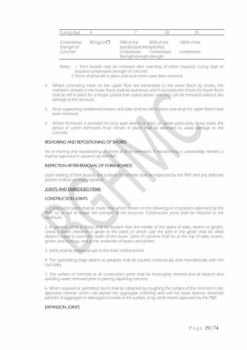
Curing days 4 7 20 25
Compressive 80 kg/cm 50% of the 85% of the 100% of the Strength of specified specified specified Concrete compressive Compressive compressive Strength strength strength
Notes: 1. form boards may be removed after reaching of either required curing days or
required compressive strength of concrete. 2. Shore shall be left in place until both them have been reached.
4. Where concreting loads on the upper floor are transmitted to the lower floors by shores, the member’s stresses in the lower floors shall be examined, and if necessary the shores for lower floors shall be left in place for a longer period than stated above until they can be removed without any damage to the structure.
5. Struts supporting cantilevered beams and slabs shall be left in place until struts for upper floors have
been removed.
6. Where formwork is provided for long span beams or slabs, or carries particularly heavy loads, the period in which formwork must remain in place shall be extended to avoid damage to the concrete.
RESHORING AND REPOSITIONING OF SHORES
No re shoring and repositioning of shores shall be permitted. If repositioning is unavoidably needed, it shall be approved in advance by the PMT.
INSPECTION AFTER REMOVAL OF FORM BOARDS
Upon striking of form boards, the surfaces of concrete shall be inspected by the PMT and any defective portion shall be promptly repaired.
JOINTS AND EMBEDDED ITEMS
CONSTRUCTION JOINTS
1. Construction joints shall be made only where shown on the drawings or in positions approved by the PMT, so as not to impair the strength of the structure. Construction joints shall be reduced to the minimum.
2. In general, joints in floors shall be located near the middle of the spans of slabs, beams or girders, unless a beam intersects a girder at this point, in which case the joint in the girder shall be offset distance equal to twice the width of the beam. Joints in columns shall be at the top of slabs, beams, girders and footings, and at the underside of beams and girders.
3. Joints shall be perpendicular to the main reinforcement.
4. The upstanding edge beams as parapets shall be poured continuously and monolithically with the roof slabs.
5. The surface of concrete at all construction joints shall be thoroughly cleaned and all laitance and standing water removed prior to placing adjoining concrete.
6. When required or permitted, bond shall be obtained by roughing the surface of the concrete in tan approved manner which will expose the aggregate uniformly and will not leave laitance, loosened particles of aggregate or damaged concrete at the surface, or by other means approved by the PMT.
EXPANSION JOINTS
P a g e 30 | 74
1. Reinforcement or other embedded items bonded to the concrete shall not be permitted to extend continuously through any expansion joint.
2. Pre molded expansion joint filler and sealant shall be of the type required by the drawing and shall conform to one of the following:
a. “Specification for Preformed Expansion Joint Filler for Concrete (Bituminous Type)” (ASTM D944) or approved equivalent. b. “specifications for Preformed Expansion Joint Fillers for Concrete Paving and Structural Construction (Non extruding and Resilient Non bituminous Types)” (ASTM D1752) or approved equivalent
JOINTS IN SLABS ON GRADE
Joints in the slabs on grade or concrete pavements shall be located and detailed as indicated in the
drawings. If saw-cut joints are required or permitted, cutting shall be timed properly with the set of the concrete: cutting shall be started as soon as the concrete has hardened sufficiently to prevent aggregates being dislodged by the saw, and shall be completed before shrinkage stress became sufficient to produce crackling.
EMBEDDED ITEMS
1. All sleeves, inserts, anchors, and embedded items required for adjoining work or its support shall be placed prior to concreting.
2. All sub-contractors whose work is related to the concrete of must be supported by it shall be given ample notice and opportunity to introduce and/or furnish embedded items before the concrete is placed.
3. Expansion joint material, water stops, and other embedded items shall be positioned accurately and supported against displacement.
4. Voids in sleeves, inserts and anchor slots shall be filled temporarily with readily removable materials to prevent the entry of concrete or mortar into the voids.
CONRETE PLACING AND CURING
1. Before placing concrete, all formwork shall be thoroughly sprinkled with water.
2. Construction joints shall be provided as the approved program (see 9.1 b) Special care shall be taken to follow the construction joint ‘shutter stop’ and finish the concrete true to line and level with the top surface of the ‘stop’. Also all starter bars be well protected with taped polythene to prevent rust from staining the surface of concrete.
3. While placing concrete, the coarse aggregates shall be worked back from the forms, leaving a full surface of mortar but avoiding the production of surface voids.
4. Vibrators shall be allowed to contact the formwork for expose concrete surfaces.
5. After removal of formwork, where necessary, the surface of fair-faced concrete shall be protected against staining by suitable Kraft paper and against physical damage by adequately robust boards or sheet material.
6. After striking the formwork, all concrete surface shall be inspected by the PMT, it shall be promptly treated in the approved manner (see 9.1b)
P a g e 31 | 74
CHAPTER IV: REINFORCEMENT
A. GENERAL
1. This subsection covers steel reinforcement for cast- in-place concrete, where indicated on the drawings, where required and as specified herein.
2. Shop drawings, showing all fabrication dimensions and locations for placing of reinforcing steel and accessories shall be submitted to the PMT for his approval. Approval shall be obtained before fabrication.
3. Details of concrete reinforcement and accessories not covered herein nor on the drawings shall be in accordance with the regulations of “Building Code Requirements for Reinforced Concrete” (ACI 318) and “Manual of Standard Practice for Detailing Reinforced Concrete Structure” (ACI 315)
B. FABRICATION
1. Prior to the fabrication and placing of reinforcing steel, the Contractor shall prepare detailed fabrication and placing drawings and submit them to the PMT for his approval.
2. Bars with bends not shown on the drawings shall not be used.
3. All reinforcement shall be accurately bent cold to the required sized and shape with care taken not to damage it
4. Bars used for concrete reinforcement shall meet the following requirements for fabricating tolerances:
a. Sheared length : +2.0 cm
b. Depth of truss bars : +1.5 cm
c. Overall dimension of : +1.5 cm
Stirrups, ties and Spirals
d. All other bends : +2.0 cm
C. PLACING
1. Reinforcing steel shall be accurately placed and spaced in accordance with the drawings. All bars shall be firmly supported and fastened together to prevent displacement during the placing of concrete. Over formwork, concrete metal, plastic or other approved bar chairs and spacers which will not adversely affect the concrete shall be used
2. Minimum concrete protective covering for reinforcement shall conform to the standard details of the
drawings and within a tolerance of +5 mm for slabs and +10mm for all other members
3. The intersections of all bars shall be securely tied with galvanized soft iron wire of not less than 1.20 mm in diameter in compliance with TIS 138, the ends being turned into the body of the concrete.
4. Bars shall be placed within the following tolerance:
a. Clear distance to formed surfaces : +0.6 cm b. Minimum spacing between bars : +0.6 cm c. Top bars in slabs and beams Members 20 cm deep or less Members more than 20 cm but Not over 60 cm deep
: :
+1.3 cm +2.5 cm
d. Crosswise of members : Spaced evenly within 5.0 cm e. Lengthwise members : +5.0 cm
P a g e 32 | 74
5. Bars may be moved as necessary to avoid interference with other reinforcing steel, conduits or embedded items. If bars are moved more than one bar diameter, or enough to exceed the above tolerances, the resulting arrangement of bars shall be subject to approval.
6. Vertical bars in columns shall be offset at least one bar diameter at lapped splices as shown on the drawings.
7. No reinforcement shall be embedded after concreting.
8. Unless permitted by the PMT, reinforcement and column dowels shall not be bent after being embedded in hardened concrete. If any correction in the position of reinforcement of dowels by bending is necessary after concrete has been placed, the reinforcement position shall be corrected over as long as possible a distance with a deviation of not more than 1:7.
D. CLEANING OF REINFORCEMENT
1. All reinforcement, at the time concrete is placed, shall be free from mud, oil, and paint, lose scale or other materials which may adversely affect or reduce the bonding capacity.
2. After bending and placing of reinforcement, not more than a light rust of ferrous oxide will be permissible before concreting commence.
3. Where loose rust scaling has occurred on bars, the bars shall be well brushed with stiff wire brushes to remove all loose scale.
4. Where reinforcing bar are kept exposed for a long period after placing, they shall be inspected again before concreting and cleaned as necessary.
E. SPLICES
1. All splices in reinforcing bars shall be made with a lapped splice. Other suitable means of splicing may be used subject to approval of the PMT.
2. The locations, length and anchorage of splices shall be as specified on the drawings. Any changes in locations shall be subject to the approval of the PMT.
3. All splices not shown on the drawings shall be subject to approval of the PMT.
F. INSPECTION AND REPAIR
1. All reinforcement after placing shall be inspected and approved by the PMT before concrete placing.
2. All incorrect position and location of reinforcement shall be promptly repaired, and all mis- fabricated and damaged bars removed and replace with new bars, as directed by the PMT.
G. PAYMENT METHODOLOGY The work under this item shall be measured by the weight of Reinforcing steel actually installed as per planned. Excess of the quantity due to Contractors corrections such as increase of dimensions shall not be considered in the pay item. For a work to be considered finished, the surface must have undergone all the necessary work from surface preparation to final coating of paint. The quantities to be paid shall only include those of which completely finished, inspected and acceptable to the PMT.
For uniformity of computations, the weight of Deform reinforcing bars shown at table below shall be used in this contract.
The work to be undertaken in this section shall comprise the furnishing, fabrication, reassembly in site, painting, delivery, erection, and installation of all materials including anchor bolts, base plates, erection bolts, bracing and all other structural steel work indicated in the plans or specified herein. SUBMITTALS The contractor shall submit to the PMT for his approval of samples of all materials required of this section such as but not limited to:
a. Fabrication drawings. Prior to the commencement of the work, Contractor shall submit construction drawings and details to the PMT for his approval of the position of the Structural Steel and layout of steel section.
b. Fabricator certificates. Prior to the commencement of the work, Contractor shall submit construction drawings and details to the PMT for his approval of the position of the Structural Steel and layout of steel section.
c. Material test results. Dimensions conformity, Bending and Tensile stress test results d. Weld test results. X-ray weld test results
MATERIALS
a. Unless otherwise indicated in the plans, structural steel shapes and plates shall conform to
ASTM -A36. Certified Mill Test and shall be submitted by the fabricator to the PMT. b. Light-Gauge Cold-formed structural steel shall conform to pertinent specifications of the
American Iron and Steel Institute (AISI) c. Machine Bolts shall conform to ASTM A-307. Each bolt shall be provided with standard nuts
and washers. d. Anchor Bolts shall conform to ASTM A-141 e. Cross Bracing with turnbuckles shall conform to ASTM A-307 f. Welding shall conform to AWS standard, and E60 or E70 electrodes shall be used unless
otherwise specified by the Structural Engineer. g. The fabricator shall have the welds tested by X-ray method by an independent company
engaged in non-destructive testing as directed by the Structural Engineer. The welds are considered satisfactory if 9 out of 10 samples passed the requirement otherwise the welds shall be corrected.
FABRICATION
a. Field fabrication shall be kept to a minimum. Shop fabrication shall be employed to the greatest extent possible with members’ shop fabricated as practicable with a minimum requirement for
field connections. b. Contractor shall submit shop drawing showing complete detailed connections for approval by
the Structural engineer. No material shall be ordered nor fabrication started until the PMT approves such drawings.
c. All dimensions in the plans shall be verified by the steel fabricator in the field in coordination with the Contractor and the PMT.
d. Unless otherwise specified in the plans, gusset plates and stiffeners shall be minimum thickness of 6 mm.
e. Splices shall be kept at minimum and shall be staggered. No splices shall be permitted at point where critical stressed occur. Splice plate shall have a minimum length of 300 mm. the contractor shall submit drawing for the locations of splice for the structural engineer’s approval.
f. All bearing plates shall have a minimum thickness of 12 mm g. All erection bolt holes shall be 3 mm plus nominal bolt diameter h. All cuttings shall be neat cut i. Shop paint (epoxy primer; 2 coats) shall be provided.
P a g e 35 | 74
j. Any work that is not in conformance with these specifications will be rejected at any time during the progress of the works.
ERECTION
a. The erection of all structural steel shall conform to the applicable requirements of the AISC Specification and AISC Code of Standard Practice. All structural steel work shall be erected accurately to the lines and levels shown on the Drawings. All columns and other vertical members shall be plumb and horizontal members level before permanent connections are made. All temporary bracing, guys and bolts as may be necessary to insure the safety of the structure until the permanent connections have been made shall be provided by the Contractor. Members shall be connected, as erection progresses, to resist all dead load, wind and erection stresses.
b. Bolted Connections. Malling faces of bolted connections shall be cleaned to bare steel, free from paint, grease and other foreign matter. Field connections shall be accurately fitted up before the bolts are taken up. Drifting shall be only such as will bring the parts into position and shall not be sufficient to enlarge the hole or to distort the metal. All unfair holes shall be drilled or reamed. After
joints are fitted up properly, bolts shall be tightened by the turn-of-nut method.
c. Cutting and Burning. The use gas-cutting torch in the field for correcting fabrication errors will not be permitted on any major member in the structural framing. Its use may be permitted on minor members if the member is not under stress and then only after the written approval of the Structural Engineer has been obtained.
d. Tolerances. The tolerances of erection and fabrication of structural steel, unless otherwise specified, shall comply with the AISC Specification. The maximum deviation from true vertical shall be one part in 500.
P a g e 36 | 74
CHAPTER IX: TINNERY WORK
GENERAL Scope The section covers the requirements for providing all the roofing work at the Project site. The work shall include all the furnishing all the labor, materials, equipment, tools and transportation necessary to complete the roofing work indicated on the drawings and the specified herein.
Drawings Prior to the commencement of the work, the Contractor shall submit construction drawings and details for the PMT for his approval.
Samples
The Contractor shall submit to the PMT for his approval samples of all materials required in this section.
MATERIAL Metal roofing
a. Accessories and fasteners of roof tiling, such as ridge tiles, gable tiles, galvanized battens and rafters, nails, screws, and wires shall be manufacturer’s standard and conform for the requirements of applicable to the Industrial Standard. b. Galvanized steel sheet sealing strip shall be used at eves- end of roof tiling against entering of birds.
WORKMANSHIP Roof Tile
Roof tile shall head lap 75- 100 mm, side lap 35 mm and shall be fastened by stainless nail. Top course tile should always be a full tile and tiling shall be staggered line. Roof tile should be well arranged to prevent rain water from entering the building. At ridge the gable roof tiling joining the wall, reinforced beam shall be made and covered to prevent rain water getting into the building and be sealed by mortar bed.
P a g e 37 | 74
PART V: CIVIL WORKS
CHAPTER I: MASONRY WORKS
A. GENERAL
This section covers the furnishing and installing complete on all stone work, and concrete blocks shown on the drawings and as specified.
B. SUBMITTALS
DRAWINGS
Prior to the commencement of the work, Contractor shall submit construction drawings and details to the PMT for his approval of the position of the reinforced concrete and joint layout of blocks. Unless otherwise specified, of the contactor or his sub-contract shall furnish all materials, tools, equipment, apparatus, appliances, transportation, labor, and supervision required to furnish and place all cement and masonry works shown on the Drawings and as specified herein.
SAMPLES
The contractor shall submit to the PMT for his approval samples of all materials required of this section.
C. MATERIAL
A. Masonry Products
1. Reinforced concrete blocks and structure concrete blocks shall conform on requirements
of JIS A 5406 (Hollow concrete block) and shall be 1st class and no defects. 2. Concrete blocks shall comply with JIS A 5406 (Hollow concrete block) C-Grade unless
otherwise specified. 3. Maximum grain of coarse aggregate for concrete fill shall be less than 1/5 width of
maximum void of block. Sand for mortar for joint of block shall be passed through sieve 2.5 mm clean and hard.
4. Reinforcement bar and binding wire shall conform to CHAPTER VI of Part IV 5. Deformed bar and other special steel shall be stated in the particular specification. 6. Water-proof agent for water-proofed mortar shall conform to Section 7 Water-proofing
work. 7. Mixture for mortar bedding and filling shall be class B (Cement: Sand=1:3)
B. Concrete Hollow Block Unless otherwise specified, concrete hollow blocks shall be in modular dimensions. Blocks shall be standard machine vibrated and shall have fine, even texture and well defined edges. The load bearing concrete hollow blocks shall have a minimum compressive strength of 1,000 psi computed for the individual unit. For non-load bearing, 350 psi computed form the average of five (5) units based on the average area and a minimum of 300 psi for the individual unit.
1. Visual Inspection b. All units shall be sound and free form cracks and other effects that interfere with the
proper placing of unit or impair the strength or permanence of the construction.
c. Units that are intended to serve the base for stucco shall have a sufficient rough surface to afford good bond.
P a g e 38 | 74
d. All units shall bear mark of the manufacturer or shall be otherwise readily identified as to origin.
2. Sample and Testing
a. Samples shall be taken to the delivered batch and shall be represented by three (3) blocks
for every thousand pieces of strength, absorption and moisture content determinations. b. Units shall be tested to the accordance with the Standard Method of Masonry Units of the
American Society for Testing Materials (ASTM) Designation C- 140 and or by the Division of Materials Testing and Physical Research, Ministry of Public Highways. No blocks shall be used unless result of the tests are known and duly approved by PMT.
c. Test shall be at the expense of the Contractor.
3. Rejection
a. In case the shipment of the CHB to conform for the requirements, the manufacturer sorts it
and new specimens shall be selected again on random from the retained lot and expense of the Contractor. In case the second sets of specimens fail to conform the test requirements, the entire lot shall be rejected.
b. Cement shall be Port Land Cement conforming to ASTM Specifications C- 150 type 1.
c. Water for mixing shall be clean, portable and free from injurious amounts of oil, soluble salts, acids, alkalis of organic matter, or other deleterious substances.
d. Sands shall be clean, hard and deleterious substances.
e. Lime shall be type S, ASTM Specifications C207 for hydrated lime for masonry purpose or quick lime for structural purposes C- 5.
f. Reinforcements 1. Lintel and vertical reinforcing bars shall conform to ASTM Specifications A- 15 “Specification
of Billet Steel Bars of Concrete Reinforcements”. Allowable fs = 18,000psi. 2. Horizontal reinforcing bars shall conform to ASTM Specifications A- 82.
4. Anchors and Tiles
a. For metal anchoring devices such as angles, slots, and bars, anchor clips, dowelling pins, and
dwelling tubing, use galvanized metals as shown on plans. b. Galvanizing procedure shall be in accordance with ASTM Specimens.
D. WORKMANSHIP
Delivery, Handling, Storage and Protection
A. Masonry Units Immediately upon delivery upon delivery to site, concrete masonry shall be stocked on platforms or stored in such manner as to protect them from contract with soil or weather care in handling masonry units shall be exercised to avoid chipping and breakage. Strong piles stocks or bins shall be protected from unnecessary traffic construction or operations or any kind of damage.
B. Lime and Cement Materials Cement and limes shall be stored off the ground under weather tight cover and away from sweating walls or other damp surfaces until ready for use. Damaged or deteriorated materials shall be removed from the premises.
Mixing Mortars
P a g e 39 | 74
Mortars shall be prepared in batches of volume and used before initial set takes place, in no case longer than 45 minutes before delivery to mason mortar board at points of use. Mortar shall be mixed in clean mechanical mixer with only sufficient water to produce required plasticity conforming of one (1) part Portland cement, ¼ part hydrated limes and three parts sand. Re- tampering of mortar after began to set shall not be permitted.
Erection
A. Wet the block thoroughly before using. The first row of blocks must be thoroughly anchored to the concrete walls, columns and slobs. Coarse shall be running bond and vertical faces truly vertical and set true to line.
B. All horizontal and vertical reinforcing bars shall be anchored 10 mm dia. into the concrete walls, columns and slabs. Dowel bars are properly placed into the walls columns or slabs during pouring and hooked to the vertical bar and leaving another 10 mm dia. exposed to the splice to the reinforcing bars
of the hollow block walls during construction.
C. Reinforcements for 100 mm thick hollow block shall consist of 10 mm diameter at 0.6 m vertical bars and 10 mm diameter horizontal bar for every 3 layers of blocks. Reinforcement for 150 & 200 mm thick shall be 10 mm diameter bar spacing the same as that 100 mm thick concrete hollow block. All cells of concrete hollow blocks below and above ground level shall be filled with 1:3 cement mortar. Bond beam shall be filled with class “A” (1:2:4). Pours shall be stopped five (5) cm. below of a top of a coarse to form a key of four (4) joints. Reinforcing bars shall have a lap of 40 x bar diameter. All horizontal reinforcements shall be tied to the vertical reinforcements of their intersection.
Note: Reinforcement of CHB identified or specified on structural plans shall govern over the reinforcement specified herein.
D. at door and window openings, unless otherwise shown on detail, the jamb blocks and beam blocks over opening and below window sill shall be reinforced as follows:
1. Jamb blocks for 100 mm and 150 mm thick walls, use two (2) 10 mm diameter bars. 2. Jamb blocks for 200 mm thick walls, use two (2) 10 mm diameter bars. 3. Beam blocks below window sill, use two (2) 10 mm bars for 100 mm, 150 mm, and 200 mm thick walls. 4. Beam blocks for 100 mm and 150 mm thick walls, use two (2) 12 mm dia. bar up to 1.20 m wide. 5. Beam blocks over opening for 200 mm walls, use two (2) 12 mm dia. bar up to 1.50 m wide. 6. Reinforcing over for beam blocks over opening other that those specified above are shown on plans.
Surface Treatment and Furnishing
The exposed surface of the concrete hollow blocks without specific finish shall be 12mm cement mortar into two (2) applications (scratched and finished coats) consisting of 15.9kg (94 1bs.) of PORTLAND Cement, and 0.11 cu. m. (4 cu. ft.) of clean river sand properly screened and all thoroughly mixed together before the necessary amount of water is added to form a workable mix. The scratch coat shall be left to season fully for at least three (3) week to about a month. After this period, keep the surface wet at least two (2) hours before applying the finished coat.
E. REPAIR, POINTING, AND CLEANING
Repair
P a g e 40 | 74
Masonry units which are loose, chipped, broken stained or damaged shall be removed and replaced, and new units shall be provided to match adjoining units and installed in fresh mortar and gout.
Pointing
Upon completion of all work, all holes and joints are exposed masonry surface shall be pointed completely filling with mortar.
Cleaning
After pointing, all exposed masonry shall be wetted and then cleaned with a 10 percent solution of muriatic acid, applied with stiff fiber brushes leaves the masonry clean, free or mortar daubs, and thigh mortar joints throughout.
Immediately after cleaning, masonry surfaces shall be rinsed down with clean, clear water.
Visual Inspection a. All units shall be sound and free from cracks or other defects that interfere with the proper placing of unit or impair the permanence of the construction. b. Units that are intended to serve as a base of plaster or stucco shall have sufficiently rough surface to afford good bond.
F. PAYMENT METHODOLOGY The work under this item shall be measured by the area of actually installed as per planned. Considered area surface area are those of which covered by gypsum/fiber cement board only disregarding support extensions. Excess of the quantity due to Contractors corrections such as increase/decrease of dimensions shall not be considered in the pay item. The pay item shall be in inclusive of all the materials and labor required to accomplish this work. For uniformity, the method of measurement shall be used:
1. Measure the area of the CHB wall using the center of wall along its thickness. 2. Openings such as doors and windows shall not be considered as pay item 3. Structural members, lintel beams and stiffener columns shall not be considered in the
computation of area as these are different items of work. For a work to be considered finished, the wall must have undergone all the necessary work from framing to installation of board walls. The quantities to be paid shall only include those of which completely finished, inspected and acceptable by the PMT.
P a g e 41 | 74
CHAPTER II: PLASTERING WORKS
GENERAL 1. Scope This section covers the requirement for providing all plastering work at the Project site. The work shall include furnishing all labor, materials, equipment, tools and transportation necessary to complete the plastering work indicated on the drawings and specified herein.
2. Materials Cement Cement shall be ordinary Portland cement and white cement conforming to JIS R 5210 “Portland Cement”
Sand
Sand shall be clean, hard and free from soil, salt and other organic foreign matter. The grading of sand shall be as follows.
Coat Percentage by weight passing sieves
Scratch and Passing 5 mm sieve : 100% Brown Coat Passing 0.15 mm sieve : 10%
Finished Coat Passing 2.5 mm sieve : 100% Passing 0.15 mm sieve : 10%
Water Water shall be clean and free from objectionable salt, iron, sulfur and other organic matte. 3. Storage of Materials
a. The Contractor shall inspect the brand and quality of all materials and store them neatly to prevent damage and mixing. b. Cement and plaster shall be stored off the ground in a storage shed and kept absolutely dry. No pile of bags shall exceed 10 bags in height.
4. Workmanship
Protection a. The Contractor shall provide proper protection so as to prevent damage to adjacent finished surfaces such as door frame and window frame during plastering work to the satisfaction of the PMT. b. All surfaces to be plastered shall be protected by sheets or other appropriate covering to prevent them from becoming excessively dry due to exposure to the sun or wind. c. All plastered surfaces shall be properly protected to prevent any dirt, stains or damage from spoiling work. Prevention of Cracks a. Where any adhesives are used on the bed surfaces or mixed into the cement mortar, they shall be approved by the PMT. b. Connections of different materials and other portions prone to cracks shall be provided with pointed joints. c. Where surface abrasion is observed on the plastered surfaces, they shall be chipped of and be made good to the satisfaction of the PMT. d. Where cracks occur on the scratch coat or the brown coat, they shall be filled and sanded before the following coat. e. Large areas of plastered surfaces of floors exposed to weather shall be provided with expansion joints not more than 4-5 m unless otherwise noted and detail shall be as follows. Draw illustration
P a g e 42 | 74
Recess by plastic or wooden Mold & sealed f. Scratch and brown coat shall be left at least 1 month before finish coating. g. Wall control joints: see 4.4 application f. wall joints Mix Proportions and Thickness of Cement Mortar The mix proportions and thickness of cement mortar shall be as follow:
Mix ( by volume) Thickness (mm)
Base Location Scratch Brown and Scratch Brown Finish Total Coat finish coat coat coat coat
Concrete Floor 1:3 1:3 21 6 27 and or under bed Brick Floor finish 1:2.5 1:2.5 30 30 Interior wall 1:2.5 1:3 6 15 3 24
For brown and finish coats of interior walls, admixtures may be mixed to a proportion 1:3 (cement admixture) subject to the PMT’s approval.
Application a. Base Preparation All the base surfaces to be plastered shall be thoroughly cleaned immediately before plastering.
The base surfaces shall be dampened to have a regular absorption characteristic. b. Mixing of Plastering Materials All plastering materials shall be mixed in power- operated mixer to ensure a uniform distribution of materials. c. Scratch coat A scratch coat shall be adequately trowel led on the bed surface to prevent voids on coated surfaces,
and be scratched to provide an adequate key for the following coat.
Coated surfaces shall be left at least two weeks to allow cracks to occur for the interior and four weeks for the exterior. The cracks shall then be filled and sanded smoothly before the application of the following coat.
d. Brown coat A brown coat shall be screeded and wood floated Corners and reveals shall be screeded before brown coating e. Finish coat
When the brown coat has properly dried, the finish coating shall be applied in such a manner as will produce perfectly smooth surface. Reveals shall be coated to form an even surface of accurate dimension.
Trowel led finishes shall be achieved with a steel finishing trowel when the surfaces have properly dried.
Brush finishes shall be formed using a brush in a regular pattern after wood floating. For wet brushing, care shall be taken that excessive water is not used.
f. Wall Control Joints & Reinforcement
Wall to be plastered shall be provided with plastering battens to ensure a straight and accurate surface. After the area has been plastered the battens shall be carefully removed and the gap pointed smooth.
All plastered finishes shall have control joint & reinforcement with joint metal devises for the purpose to allow movement of finish material. Divided area of these finishes shall be approx. every 5-6 m, and necessary reinforcement shall be taken as mentioned below unless otherwise noted in the Drawings.
P a g e 43 | 74
These conditions shall be strictly carried out in any parts of the building to avoid the crack and no exception shall be accepted.
The expansion reinforcement devices shall be manufactured by the Expanded Metal Co., Ltd. (EXPAMET) as follows or approved equivalent.
Forms movement joints in render: Movement bead w/ PVC extrusion Forms & protects lower “bell cast” edge: Render stop Finishes render edges for doors & windows: Stop bead Conner applications: Angle bead Render joints between conc. Structures and brick or conc. Block: Rib-lath
Notes: For the application of above mentioned devices for outdoor & semi-outdoor where covered area but not enclosed as interior, interior of toiled, shower room & other humid rooms, materials shall be stainless steel and for interior use other than above, steel material can be used.
g. Floor Screeding
Concrete surfaces shall be chipped off to remove laitance, cleaned and dampened.
A guide or leveling string shall be used to indicate the finished levels of the screed.
Mortar shall be applied with a brush to the concrete surface and then a stiff-mixed screed shall be applied as the first coat to be screeded.
When the screeded surfaces have properly set, a 6 mm finish coat shall be applied and be well trowel led.
P a g e 44 | 74
PART VI: WATERPROOFING WORK
GENERAL
Scope
This section covers the requirement for providing all the waterproofing work at the Project site. The work shall include furnishing all labor materials, equipment, tools, and transportation necessary to complete the waterproofing work indicated and drawings specified herein.
Item of Work
Item of the work shall include but not limited to the following:
a. Cement mixed waterproofing finishes. b. Polyurethane resin coating (for roof area) c. Polyurethane waterproofing (for interior floor area) d. Sealing work
MATERIAL
Waterproofing materials used shall be as follows:
a. Cement mixed waterproofing agents shall be synthetic resin type or as approved by the PMT and the owner/’s representative prior to approval and application. b. Cement and sand shall be specified in SECTION 13. The contractor shall submit a certificate and samples of the materials to the PMT for his approval before use. All water proofing materials shall be properly protected so as to prevent damage before use.
GENERAL REQUIREMENTS
Climatic Conditions
The contractor shall be responsible for determining the consultation with the PMT whether or not the waterproofing shall be carried out when rain is expected or base surfaces are wet due to rain or under inverse climatic conditions as storing winds or high humidity.
Base Preparation
a. all cement rendered and or concrete surfaces to receive the waterproofing work shall be cleaned and be free from dust, staining, oil, and laitance. b. All base surfaces shall be all finished true to slope as specified and well drained, especially around drained outlets. Waterproofing Test When the PMT deems necessary to inspect the waterproofing work, the contractor shall test in the accordance with instruction of the PMT.
APPLICATION
P a g e 45 | 74
Cement Mixed Waterproofing a. Mixing Mixing shall be conducted with accordance with Manufacturer’s Instructions. b. The waterproofing mortar shall be applied to have the thickness of 25- 30 mm and three coat work. Polyurethane Resin Coating a. Polyurethane resin coating shall be applied to the roof area where the indicated on the drawings. b. Polyurethane resin coating shall be complied as followings.
c. Corner shall be reinforced with fiber mesh after undercoat. d. Application shall be conducted in accordance with the Manufacturer’s instructions.
Polyurethane Waterproofing (Due for approval)
a. Polyurethane waterproofing shall be applied to the interior floor where indicated on the drawing.
b. Polyurethane Waterproofing shall be complied as follows. 1. Primer 2. Undercoat 3. Fiber mesh reinforcement 4. Middle coat 5. Overcoat 6. Finishing
c. Application shall be conducted in accordance with the Manufacturer’s Instructions.
CURING AND PROTECTION Cement Mixed Waterproofing Applied service shall be protected to prevent over rapid drying and be allowed to harden completely before supporting traffics. Polyurethane Resin Coating and Polyurethane Waterproofing Curing and protecting shall be done on accordance with Manufacturer’s Instructions.
SEALING WORK Materials Sealing materials shall conform to JIR\S A 5758 “Sealing Compounds for Sealing and Glazing in Buildings” and as following or approved equivalent.
a. Silicone sealing compounds b. Modified silicone sealing compounds c. Polysulfide sealing compounds d. Other materials such as primer, back- up bond breaker of curing tape shall be necessary and in accordance with Manufacturer’s Instructions.
Traders Sealing work shall be carried out by a sub- contractor with well experienced and who specialize in the work specified herein and is approved by the PMT.
P a g e 46 | 74
Application
a. Silicone sealing shall be filled for metal- metal joints, glass- glass joints and metal- glass joints. b. Modified silicone sealing shall be filled with metal- concrete or tiles joints and concrete- pre cast concrete or tiles joints as indicated in the drawing. c. Poly-sulfide sealing shall be filled for all exterior construction joints, around exterior door and windows and other joints as indicated on the drawings.
WARRANTY PERIOD Warranty period of Polyurethane resin coating and polyurethane waterproofing shall be 10 years or as per manufacturer/dealer’s standard after the date of delivery of the buildings.
P a g e 47 | 74
PART VII: ARCHITECTURAL FINISHES CHATTER I: VINYL FLOORING
A. GENERAL
The work to be undertaken in this section shall comprise the furnishing, fabrication, and installation of all materials including testing as indicated in the plans or specified herein.
B. SUBMITTALS
1. Manufacturer’s full range of samples conforming to the specifications 2. Test results required by PMT 3. Shop drawing of the layout of flooring as per actual dimensions for PMT’s approval. 4. Installer certificate
C. MANUFACTURER/SUPPLIER
Provide each type of flooring as provided by a single manufacturer, including recommended primers, adhesives, sealants, patching and leveling compounds.
D. TESTING
The following are the applicable ASTM test standards that the PMT may require to the contractor befor the approval of the materials.
1. F137 Test Method for Flexibility of Resilient Flooring Materials with Cylindrical Mandrel Apparatus 2. F141 Terminology Relating to Resilient Floor Coverings 3. F386 Test Method for Thickness of Resilient Flooring Materials Having Flat Surfaces 4. F410 Test Method for Wear Layer Thickness of Resilient Floor Coverings by Optical Measurement 5. F925 Test Method for Resistance to Chemicals of Resilient Flooring 6. F970 Test Method for Measuring Recovery Properties of Floor Coverings after Static Loading 7. F1514 Test Method for Measuring Heat Stability of Resilient Flooring by Color Change 8. F1515 Test Method for Measuring Light Stability of Resilient Flooring by Color Change 9. F1914 Test Methods for Short-Term Indentation and Residual Indentation of Resilient Floor Covering
E. MATERIAL SPECIFICATIONS
1. VINYL SCHEDULE OF FINISHES
a. Non-directional Vinyl Roll Floor Finish (F-2)
• Vinyl Composition: Homogenous throughout its thickness, Anti-static, anti-bacterial
• Dimension: not applicable
• Minimum width: 2.0 meters
• Minimum Thickness: 2 mm
• Pattern direction: Non-directional
• Finish, Color, & Pattern: As selected by Architect on Record from manufacturer’s full range (selection can be more than one (1) or combination of finish, color, or pattern)
b. Directional Vinyl Roll Floor Finish (F-1a)
• Vinyl Composition: Homogenous throughout its thickness, Anti-static, anti-bacterial
• Dimension: not applicable
• Minimum width: 2.0 meters
• Minimum Thickness: 2 mm
• Pattern direction: Directional
• Finish, Color, & Pattern: As selected by Architect on Record from manufacturer’s full range (selection can be more than one (1) or combination of finish, color, or pattern)
c. Vinyl Tile Floor Finish (F-2)
• Vinyl Composition: Homogenous throughout its thickness, Anti-static, anti-bacterial
P a g e 48 | 74
• Dimension: as per specified on plans
• Minimum Thickness: 3 mm
• Finish, Color, & Pattern: As selected by Architect on Record from manufacturer’s full range (selection can be more than one (1) or combination of finish, color, or pattern)
2. VINYL FLOORING PRIMER
a. Water based solvent free b. Low odor
3. SELF LEVELING COMPOUND a. Fast drying and ready to receive adhesive when dry. b. Bulk density of 1200 kg/m3 c. Minimum compressive strength: 22 MPA after 28 day d. Minimum tensile/bending strength: 5 MPA after 28 day
4. VINYL FLOORING ADHESIVE
a. Water based acrylic co-polymer blend b. Odorless when dry
5. COVE FORMER
a. Rubberized b. 25 mm radius
6. CAPPING STRIP
a. Vinyl cap b. Color: As selected by Architect on Record from manufacturer’s full range (selection can be more
than one (1) or combination of color)
7. FLOOR POLISH c. Protective liquid floor polish as per manufacturer’s recommendation.
F. MATERIAL DELIVERY, STORAGE AND HANDLING
All vinyl, adhesive, primers, and other accessories delivered shall be in their original containers, seals unbroken, and labelled as follows: 1. Color name or code 2. Volume/Weight content (for primers, adhesive and levelling compound) 3. Date of production and expiration date 4. Product major constituent’s contents 5. Application instructions and warnings 6. Maintenance data
G. PAYMENT METHODOLOGY
The work under this item shall be measured by the area of surface actually installed as per planned. Excess of the quantity due to Contractors corrections such as increase of dimensions shall not be considered in the pay item. The pay item shall be in inclusive of all the materials and labor required to accomplish this work. For a work to be considered finished, the flooring must have undergone all the necessary work from surface preparation to polishing and covering of floor. The quantities to be paid shall only include those of which completely finished, inspected and acceptable by the PMT.
H. INSTALLATION
1. Installer Qualifications
Installer must be experienced in performing work of this section. Whenever possible, the installer must be employed by the manufacturer of the flooring vinyl and must be certified by the manufacturer as their installer. When the installation is not to be done by direct employee of the supplier/manufacturer, the installer must have at least installed 200 sq.m. of vinyl flooring.
P a g e 49 | 74
2. Pre- installation Obtain Architect's acceptance of finish color, texture and pattern, and workmanship standard. It is the Contractor’s responsibility to comply with the following” a. Size and Location of Mock-Up: [Specify the size and location of the mock-up.] b. Maintenance of Mock-Up: Maintain mock-up during construction for workmanship comparison;
remove and legally dispose of mock-up when no longer required. c. Approval of Mock-Up: Upon the PMT’s approval of the mock-up, this installation shall be
considered the standard of quality and basis of comparison for the balance of the project. Areas to be found deficient by specification standards or application procedures shall be repaired or replaced at the contractor’s expense.
d. Incorporation of Mock-Up: The mock-up may be incorporated into final construction upon PMT’s approval.
3. Sub-floor Preparation
a. Remove substrate coatings and other substances that are incompatible with adhesives and that
contain soap, wax, oil, or silicone, using mechanical methods recommended by manufacturer b. Sand blast or grind the sub floor to obtain rugged surface. c. Apply a good quality 2 mm – 5 mm levelling compound filling layer and allow a drying time of 4 to
8 hours. d. Use an 80 grain size sand paper to obtain a smooth surface. e. Perform Alkalinity, Adhesion, moisture testing and other test required by PMT before proceeding to
installation
4. Floor Installation a. Unroll floor coverings and allow them to stabilize before cutting and fitting b. Install Capping Strips and Cove Former using contact cement and as per manufacturer’s
instructions. Cove floor coverings must be at least 100 mm high or as indicated on plans. c. Apply Primer as per manufacturer’s instructions. d. Apply floor adhesive as per manufacturer’s instructions. e. Install vinyl flooring as per manufacturer’s instructions. Adhere floor coverings to substrates using a
full spread of adhesive applied to substrate to produce a completed installation without open cracks, voids, raising and puckering at joints, telegraphing of adhesive spreader marks, and other surface imperfections.
f. Seams between adjacent areas are obtained by cutting the overlapping edges. g. Install welding rod at all seams h. Protect flooring from heavy traffic for at least 24 hours.
5. Cleaning and Polishing
a. Wet mop using a high quality floor cleaner having neutral or mild alkaline properties and follow
the instructions. Remove all stains immediately to avoid permanent marks on the floor. Stain removers to be used shall not damage the floor coverings.
b. Apply at least three (3) coats of liquid floor polish.
6. Protection before turn-over
a. After inspection and acceptance of work, the Contractor shall protect the flooring with covering
until usage by end-user.
P a g e 50 | 74
CHAPTER II: TILE WORKS
A. GENERAL This section covers the requirements for providing all the Tile works at the Project site. The work shall include furnishing and labor, materials, equipment, tools and transportation necessary to complete the tile works indicated on the drawings and specified herein.
B. SUBMITTALS The Contractor shall submit to the PMT for his approval samples of the following.
1. Manufacturer’s full range of samples tiles conforming to the specifications (Provide full size of sample for
600mm x 300mm and below, for tiles greater than 600mm x 300mm, provide at least 150mm x 150mm cut sized from original dimension)
2. Shop drawing of the layout of flooring as per actual dimensions for PMT’s approval. The Contractor shall submit to the PMT for his approval detailed drawings showing tile and terrazzo arrangements and joint layout.
a. Tiles delivered to the Project site shall be inspected and sorted by color and dimensions
before installation. b. All tiles shall be the type with dovetail of its back.
C. MATERIALS SPECIFICATIONS
1. TILE SCHEDULE OF FINISHES
a. Non-Skid Ceramic Floor Tile Finish (F3)
• Composition: Natural stone
• Tile Size: As per specified on plans/Bill of quantities
• Thickness: Minimum of 6.4 mm
• Surface: Slip-resistant (non-skid)
• Finish, Tile Color, and Pattern: As selected by Architect on Record from manufacturer’s full range (selection can be more than one (1) finish, color, or pattern)
• Grout Color: As selected by Architect on Record from manufacturer’s full range
b. Polished Ceramic Floor Tile Finish (F3a)
• Composition: Natural stone
• Tile Size: As per specified on plans/Bill of quantities
• Thickness: Minimum of 6.4 mm
• Surface: Polished
• Finish, Tile Color, and Pattern: As selected by Architect on Record from manufacturer’s full range (selection can be more than one (1) finish, color, or pattern)
• Grout Color: As selected by Architect on Record from manufacturer’s full range
c. Non-Skid Porcelain Floor Tile Finish (F4)
• Composition: Full Body Impervious Natural stone
• Tile Size: As per specified on plans/Bill of quantities
• Thickness: Minimum of 10 mm
• Surface: Slip-resistant (non-skid)
• Finish, Tile Color, and Pattern: As selected by Architect on Record from manufacturer’s full range (selection can be more than one (1) finish, color, or pattern)
• Grout Color: As selected by Architect on Record from manufacturer’s full range
d. Porcelain Floor Tile Finish (F4a)
• Composition: Full Body Impervious Natural stone
• Tile Size: As per specified on plans/Bill of quantities
• Thickness: Minimum of 10 mm
• Surface: Polished
P a g e 51 | 74
• Finish, Tile Color, and Pattern: As selected by Architect on Record from manufacturer’s full range (selection can be more than one (1) finish, color, or pattern)
• Grout Color: As selected by Architect on Record from manufacturer’s full range
e. Non-Skid Porcelain Floor Tile with Anti-slip Grooves Finish (F5)
• Composition: Homogenous Full Body Impervious Natural stone
• Tile Size: As per specified on plans/Bill of quantities
• Finish, Tile Color, and Pattern: As selected by Architect on Record from manufacturer’s full range (selection can be more than one (1) finish, color, or pattern)
• Grout Color: As selected by Architect on Record from manufacturer’s full range
f. Non-Skid Ceramic Wall Tile Finish (W4)
• Composition: Natural stone
• Tile Size: As per specified on plans/Bill of quantities
• Thickness: Minimum of 6.4 mm
• Surface: Slip-resistant (non-skid)
• Finish, Tile Color, and Pattern: As selected by Architect on Record from manufacturer’s full range (selection can be more than one (1) finish, color, or pattern)
• Grout Color: As selected by Architect on Record from manufacturer’s full range
g. Polished Ceramic Wall Tile Finish (W4a)
• Composition: Natural stone
• Tile Size: As per specified on plans/Bill of quantities
• Thickness: Minimum of 6.4 mm
• Surface: Polished
• Finish, Tile Color, and Pattern: As selected by Architect on Record from manufacturer’s full range (selection can be more than one (1) finish, color, or pattern)
• Grout Color: As selected by Architect on Record from manufacturer’s full range
h. Non-Skid Porcelain Floor Tile Finish (W5)
• Composition: Impervious Natural stone
• Tile Size: As per specified on plans/Bill of quantities
• Thickness: Minimum of 6.4 mm
• Surface: Slip-resistant (non-skid)
• Finish, Tile Color, and Pattern: As selected by Architect on Record from manufacturer’s full range (selection can be more than one (1) finish, color, or pattern)
• Grout Color: As selected by Architect on Record from manufacturer’s full range
i. Porcelain Floor Tile Finish (W5a)
• Composition: Impervious Natural stone
• Tile Size: As per specified on plans/Bill of quantities
• Thickness: Minimum of 6.4 mm
• Surface: Polished
• Finish, Tile Color, and Pattern: As selected by Architect on Record from manufacturer’s full range (selection can be more than one (1) finish, color, or pattern)
• Grout Color: As selected by Architect on Record from manufacturer’s full range
2. TILE ADHESIVE
a. Cement Based b. Low VOC Levels c. Adhesive must meet specified requirements of ANSI standard A118.1
3. CEMENT
Cement shall be ordinary Portland cement conforming to JIS R 5210 “PORTLAND CENTER”.
P a g e 52 | 74
4. SAND a. Sand shall be clean, hard and free from soil, salt and other organic foreign matter. b. The grading of sand shall be as follows:
Percentage by weight passing sieves
0.5mm 0.6mm 1.2mm 2.5mm
10% or less 100%
D. MATERIAL DELIVERY, STORAGE AND HANDLING All tiles and tiling materials delivered shall be in their original containers and seals unbroken. Store materials in a clean and neat room. The Contractor shall ensure the protection of materials from extreme temperature exposure.
E. INSTALLATION
1. Pre-Tile installation a. Apply waterproofing membrane to substrate at wet areas in accordance to Chapter XII of this
specification. b. Perform necessary test to ensure no water leaks.
2. Mortar a. Mixing proportion of cement and sand for mortar shall be 1:3 by volume. b. Grouting mortar shall be neat cement unless otherwise specified. c. Mortar shall be produced adding water within 2 hours after cement and sand are mixed. Mortar
shall be used within 40 minutes after adding water. Mortar shall be 20 mm minimum thickness and well leveled.
d. Use tile adhesive on floor before spreading cement-sand mix. Also, use tile adhesive on tile backing before laying in place.
e. If waterproofing agents or additives are used in the mortar, the quality and proportions of such materials shall be approved by the PMT.
3. Wall tiling
a. All wall surfaces to be tiled shall be thoroughly washed with clean water and leveled with mortar. All surfaces exposed with sunlight shall be protected with a suitable cover.
b. After based coats have completely set, the surfaces shall be cleaned and dampened. Stretched strings shall be ensuring accurate alignment of the joint layout.
c. Each tile shall be backed with adequate setting mortar and pressed onto the base mortar coat. d. Each tile shall be tamped in place with a wood hammer so the mortar completely covers the
back of the tile and is forced out around the tile edges. e. If the mortar is not adequate, the void shall be filled with dry- mix mortar to ensure a full backing
and pressure a plumb and true surface. In no case shall cement be use for fixing the voids. f. The interior tiling shall not exceed 1.8 m in height each day.
g. As soon as the setting motor has sufficient hardened, the tile surfaces shall be brushed, washed with clean water and wiped with a clean cloth.
4. Floor tiling
a. All floor surfaces to be tiled shall be thoroughly washed with clean water and be screened by mortar to a level surface. The base shall be laid to falls as necessary for drainage. Each mortar application shall not exceed 6 -8 m2. All surfaces exposed to sunlight shall be protected with a suitable table.
b. A bedding mastic 20 mm thick shall be provided beneath floor tiles on a leveling screed. The tiles shall be laid true to alignment without irregularities and be- well tamped with a wood hammer to force the mastic to exude around all edges of each tile as it is laid.
c. Two hours after laying the tiles shall be damped to soak and the alignment shall be checked to ensure an even joint layout without any differences between prices.
P a g e 53 | 74
d. All tiled surfaces shall be well cleaned with wet brushes, and cloths to remove all surface dirt, stains or water splashes. No foot traffic nor vibration shall be permitted within 24 hours of laying floor tiles.
5. Joints
a. All joints shall be filled with grouting mortar at least 48 hours after tiles have been laid using a rubber spatula.
b. The grouting mortar shall be used within 1 hour after adding water. c. Where the joint is not more than 3 mm, the gap shall be grouted with neat cement. d. Where the joint is between 4-7 mm, the gap shall be grouted with mortar having a cement and
sand proportion of 1:0.25 by volume.
6. Curing & protection of finish material a. All tiled surfaces shall be properly cured to prevent rapid drying for 4 weeks after tile laying. b. All tiles surfaces shall be washed down with brushes and cloths to remove smears. c. At external corners or openings liable to damage, completed tiling shall be properly protected with
wood boards. d. Floor surfaces shall be protected with both thick vinyl film and plywood at least t=3 mm for whole
area immediately after the pointing mortar application. F. PAYMENT METHODOLOGY
The work under this item shall be measured by the area of surface actually installed as per planned. Considered area surface area are those of which covered by floor finished. Excess of the quantity due to Contractors corrections such as increase/decrease of dimensions shall not be considered in the pay item. The pay item shall be in inclusive of all the materials and labor required to accomplish this work. For a work to be considered finished, the wall must have undergone all the necessary work from floor preparation up to the application of grout. The quantities to be paid shall only include those of which completely finished, inspected and acceptable by the PMT.
P a g e 54 | 74
CHAPTER III: FIBER CEMENT WALLS AND GYPSUM WALLS
A. GENERAL This section covers the requirement for providing all plastering work at the Project site. The work shall include furnishing all labor, materials, equipment, tools and transportation necessary to complete the works indicated on the drawings and specified herein.
B. SUBMITTALS
The Contractor shall submit to the PMT for his approval samples of the following.
1. Manufacturer’s full range of samples conforming to the specifications 2. Manufacturer’s specifications 3. Shop drawing of the layout of walls as per actual dimensions for PMT’s approval. 4. Test result required by PMT
C. MATERIALS SPECIFICATIONS
1. Framing System
Framing system for Studs and Tracks shall be 35 mm x 76 mm x 0.7 mm thk. Galvanized material. Metal studs shall be straight, light, non-combustible and not susceptible to termite damage. Screws and power actuated shall be used to connect framing components and fasten other materials to the framing.
2. Board Finish a. 1.2 m x 2.4 m x 6 mm thk fiber cement board Finish (W6) b. 1.2 m x 2.4 m x 12 mm thk gypsum board Finish (W7) c. 1.2 m x 2.4 m x 12 mm thk gypsum board Finish (W7a)
3. Revit and Screws As per supplier’s recommendation
D. STORAGE OF MATERIALS
1. Deliver materials in manufacturer's original, unopened, undamaged containers with identification labels intact.
2. Store materials protected from exposure to rain, or other harmful weather conditions.
E. INSTALLATION
1. Framing system Vertical studs shall be connected to the matching floor and ceiling track (runner) with pan head screws, spaced at 600 mm on center spacing. Horizontal studs shall be then installed across the vertical studs. Wallboard or other sheathing shall be then attached with type S (fine-tread) drywall screws.
2. Framing System Method of Installation a. Cut studs and track to required lengths as you install using aviator snips or circular saw with
abrasive, metal cutting blade. b. Attach ceiling track. Use drywall screws to attach to joists. For parallel joists, bridge two joists with
track spaced 61 cm o.c. or less and install ceiling runner across bridges. c. Plumb to position floor runner directly below ceiling track. d. Attach floor track. Use power-actuated fasteners for concrete floor. Use drywall screws for wood
sub-floor. Same fastener spacing as ceiling track. Then mark stud locations 40.64 cm o.c. top and bottom starting from the same end.
e. Insert stud at slight angle into tracks – then twist into place. Be sure all studs are pointed the same way for easier drywall attachment and punch-outs are oriented the same way for easy plumbing or electrical installation.
f. Screw-attach stud to ceiling track and floor track with 1.11 cm pan or wafer-head screws. Hold stud flange to runner for easier screw attachment.
P a g e 55 | 74
g. For door and window openings, cut track 10.16 cm longer than opening. Notch legs and bend web 90 deg. to attach to jamb stud.
h. Attach C-runner bracing across studs to support cabinet attachment. C-runner must be notched to fit between studs.
i. Insert grommets or pieces of pipe insulation into pre-punched holes whenever you pass through wiring or plumbing.
j. Screw-attach drywall to framing using drywall screws. Board should be attached to the open end of the studs first.
k. Install comer beads and trim with screws or staples. l. Tape and finish with joint compound
3. Drywall Board Method of Installation
a. When board is installed parallel to framing members, space fasteners shall be 200 millimeters on center in field of the board and 200 millimeters on center along edges.
b. When board is installed perpendicular to framing members, space fasteners shall be 200 millimeters
on center in field and along edges. c. Screws shall be staggered on abutting edges or ends. d. For single-ply construction, apply gypsum board with long dimension either parallel or
perpendicular to framing members as required to minimize number of joints except when board shall be applied vertically over "l" furring channels.
e. For two-ply board assemblies, apply base ply of gypsum board to assure minimum number of joints in face layer. Apply face ply of wallboard to base ply so that joints of face ply do not occur at joints of base ply with joints over framing members.
F. PAYMENT METHODOLOGY The work under this item shall be measured by the area of surface actually installed as per planned. Considered area surface area are those of which covered by gypsum/fiber cement board only disregarding support extensions. Excess of the quantity due to Contractors corrections such as increase/decrease of dimensions shall not be considered in the pay item. The pay item shall be in inclusive of all the materials and labor required to accomplish this work. For a work to be considered finished, the wall must have undergone all the necessary work from framing to installation of board walls. The quantities to be paid shall only include those of which completely finished, inspected and acceptable by the PMT.
P a g e 56 | 74
CHAPTER IV: FIBER CEMENT BOARD CEILING AND GYPSUM BOARD CEILING
A. GENERAL
This section covers the requirement for providing all ceiling work at the Project site. The work shall include furnishing all labor, materials, equipment, tools and transportation necessary to complete the work indicated on the drawings and specified herein. Board can be either of the following depending on architectural drawing. a. 6 mm thk fiber cement board Finish (C-3) b. 4.5 mm thk fiber cement board Finish (C-3a) c. 10 mm thk gypsum board Finish (C-4)
B. MATERIALS Framing system shall be straight, light, non-combustible and not susceptible to termite damage. Screws and power actuated shall be used to connect framing components and fasten other materials to the framing. Materials are the following: a. Board can be either of the following depending on architectural drawing.
• 1.2 m x 2.4 m x 6 mm thk fiber cement board (C-1)
• 1.2 m x 2.4 m x 4.5 mm thk fiber cement board (C-1a)
• 1.2 m x 2.4 m x 10 mm thk gypsum board (C-2) b. 19 mm x 50 mm x .4 mm thk. Double furring channel c. 12 mm x 38 mm x 1 mm thk Carrying channel d. Double furring clip e. Wall Angle f. 5/32" Blind rivet g. 1-1/4" Concrete nail h. Steel Angle i. Suspension Clip j. Suspension Rod
C. STORAGE OF MATERIALS
a. Deliver materials in manufacturer's original, unopened, undamaged containers with identification labels
intact. b. Store materials protected from exposure to rain, or other harmful weather conditions.
D. WORKMANSHIP
a. Fix and align accurately all steel angles at the maximum interval of 1.20 meter for longer side and maximum interval of 0.8 meter for the shorter side.
b. Tie the suspension rod securely to the steel angle. c. Attach the carrying channel to the suspension clip then use the rod joiner to connect the suspension
rod to the suspension clip. d. Attach the metal furring to the carrying channel at right angle to each other using the furring clips.
Metal furring shall be spaced with maximum distance of 0.40 meter o.c. and carrying channel shall be spaced with maximum distance of 1.2 meter o.c.
e. Ceiling boards (gypsum or fiber-cement) are attached to the metal framing by drywall screw. Screw shall be spaced at a maximum of 200 mm o.c.
F. PAYMENT METHODOLOGY The work under this item shall be measured by the area of surface actually installed as per planned. Considered area surface area are those of which covered by gypsum/fiber cement board only disregarding support extensions. Excess of the quantity due to Contractors corrections such as increase/decrease of dimensions shall not be considered in the pay item. The pay item shall be in inclusive of all the materials and labor required to accomplish this work.
P a g e 57 | 74
For a work to be considered finished, the wall must have undergone all the necessary work from framing to installation of board ceilings. The quantities to be paid shall only include those of which completely finished, inspected and acceptable by the PMT.
P a g e 58 | 74
CHAPTER V: PVC CEILING
A. GENERAL
This section covers the requirement for providing all ceiling works using PVC ceiling at the Project site. The work shall include furnishing all labor, materials, equipment, tools and transportation necessary to complete the work indicated on the drawings and specified herein.
B. MATERIALS
Framing system shall be straight, light, non-combustible and not susceptible to termite damage. Screws and power actuated shall be used to connect framing components and fasten other materials to the framing. Materials are the following: a. 200 mm wide PVC Ceiling Panels (C-7, b. 19 mm x 50 mm x .4 mm thk. Double furring channel c. 12 mm x 38 mm x 1 mm thk. Carrying channel d. Double furring clip e. Wall Angle f. 5/32" Blind rivet g. 1-1/4" Concrete nail h. Steel Angle i. Suspension Clip j. Suspension Rod k. Steel Angle Bracket l. 3/8" Hex bolt w/ washer
C. STORAGE OF MATERIALS
c. Deliver materials in manufacturer's original, unopened, undamaged containers with identification labels
intact. d. Store materials protected from exposure to rain, or other harmful weather conditions.
D. WORKMANSHIP
a. Fix and align accurately all steel angles at the maximum interval of 1.20 meter for longer side and
maximum interval of 0.8 meter for the shorter side. b. Tie the suspension rod securely to the steel angle. c. Attach the carrying channel to the suspension clip then use the rod joiner to connect the suspension
rod to the suspension clip. d. Attach the metal furring to the carrying channel at right angle to each other using the furring clips.
Metal furring shall be spaced with maximum distance of 0.40 meter o.c. and carrying channel shall be spaced with maximum distance of 1.2 meter o.c.
e. PVC ceiling panels are attached to the metal framing by drywall screw. Screw shall be spaced at a maximum of 200 mm o.c.
F. PAYMENT METHODOLOGY The work under this item shall be measured by the area of surface actually installed as per planned. Considered area surface area are those of which covered by PVC Ceiling only disregarding support extensions. Excess of the quantity due to Contractors corrections such as increase/decrease of dimensions shall not be considered in the pay item. The pay item shall be in inclusive of all the materials and labor required to accomplish this work. For a work to be considered finished, the wall must have undergone all the necessary work from framing to installation of PVC ceilings. The quantities to be paid shall only include those of which completely finished, inspected and acceptable by the PMT.
P a g e 59 | 74
CHAPTER VI: ACOUSTIC CEILING
A. GENERAL
This section covers the requirement for providing all ceiling works using acoustic ceiling at the Project site. The work shall include furnishing all labor, materials, equipment, tools and transportation necessary to complete the work indicated on the drawings and specified herein. Board can be either of the following depending on architectural drawing. a. 600 x 600 x 15 mm or 600 x 1200 x 15 mm Fiber Mineral Acoustic Ceiling Finish (C-5) b. 600 x 600 x 15 mm or 600 x 1200 x 15 mm Non-Perforated Clean Room Rated Acoustic Tiles (C-6)
B. MATERIALS
Framing system shall be straight, light, non-combustible and not susceptible to termite damage. Screws and power actuated shall be used to connect framing components and fasten other materials to the framing. Materials are the following: a. Fiber Mineral Acoustic Ceiling / Non-Perforated Clean Room Rated Acoustic Tiles b. Main Tee Runner 10’-12’ Length Powder Coated c. Cross Tee 4' Length Powder Coated d. Cross Tee 2' Length Powder Coated e. Wall Angle Powder Coated f. #10 GI Wire Hanger g. Steel Angle Bracket h. 3/8" Hex bolt w/ washer i. 1-1/4" Concrete nail
Suspension System a. Ceiling tile manufacturer;s standard suspension system fabricated of cold-rolled hot-dipped galvanized
sheet steel components providing minimum 170 g/m2 zinc coating conforming BS 2989 or ASTM A 653. System shall be designed and fabricated to meet the requirements of ASTM C 635 or equivalent BS standards. Finish shall be electro-statically applied lpowder coated polyester paint, whit color or as approved by the Consustant.
b. Accessories: Edge Moldings, hold-down clips and other necessary accesories shall be provided in accordance with the consulatnts selection and approval.
Acoutical Ceiling Tile: a. Acoustical ceiling tiles shall be of mineral fiber of modular design and sizes and shall be of size 600 x 600
x 15 mm thk, unless otherwise indicated on the drawings. Tiles shall be fit the pattern as shown on the drawings. Mineral fivver tiles conforming to BS 476, class O, Class 1 or ASTM E 1264 or Federal Specifications FS-SS-S-118B, Type III,, form 1 units; Class A; STC Range of 34-40 Db; nrc FROM 0.50 TO 0.70; DENSITY OF 240-260 KG/M3; rh OF 90%; Flame Spread of 0-25 and Smoke Developed 0-50 in accordance with ASTM E 84 or equivalent standards.
b. Finish. Factory-applied washable white finish or as shown in the drawing and approved by the PMT, with light reflectance value of LR over 75 percent.
c. Access Hatches: Provide manufacturer standard access hatches which are designed specially for the acoustical ceiling systems. Provide the access hatches with complete features including door locks, frames, pivots, metal trims and gaskets.
C. STORAGE OF MATERIALS
Deliver materials in manufacturer's original, unopened, undamaged containers with identification labels intact. Store materials protected from exposure to rain, or other harmful weather conditions.
D. WORKMANSHIP
1. Suspension system a. Installation of suspension system shall be in accordance with BS 8290 or ASTM C 636 and in
accordance with manuacture’s directions b. Rough suspension
P a g e 60 | 74
• Space hanges wires at a maximum 900 mm on centers, each direcion. Supported to Steel angle by looping and wire tying.
• Hanges shall be installed at ends of each suspension member and at light fixtures, 150mm from vertical surface.
• Wires shall not be splayed more than 125 mm in a 1200 mm vertical drop
• Wire shall be wrapped a meinimum of three times horizontally, turning the ends upward. c. System shall be level within tolerance specifiesd and parallel with walls. d. Wall moldings shall be installed at intersetion of suspended ceiling an vertical surfaces.
• Corners sjall be mitered whiere wall moldings interxesct or coenwe caps shall be installed in lieu therof
• Continuous ribbon of acoustical adhesive or caulding compound shall be appllied on vertical web
• Attachement to vertical surfaces shall be by means of mechanical fasteners.
2. Ceiling Tiles
a. Installation of acoustical ceiling shall not begin until the building has been closed to weather with relative humidity not more thatn 70%
b. Ceiling tiles shall be in a leveled lplane and in straight line courses c. Provife sutting and patching for the passage of materials of other trades.
P a g e 61 | 74
CHAPTER VII: PAINTING WORKS
A. GENERAL
This section covers the requirements for performing all the painting work at the Project site. The work shall include furnishing all labor, materials, equipment, tools and transportation necessary to complete the painting work indicated on the drawings and specified herein.
B. SUBMITTALS
• Product Data: Manufacturer’s data showing conformance to the specification specified
• Color Swatches: Manufacturer’s complete range of colors for selection
• Sample actual color from the selected color swatches
C. MATERIALS Painting materials shall conform to specifications and approved by the PMT. The Contractor shall submit a certificate to the PMT, if required.
Any auxiliary materials for painting shall be those compatible with properties of the respective paint as designated by the paint manufacturer or approved by the PMT. The Contractor shall submit a paint sample to the PMT for their approval for each type of paint to show the finish given by it. All materials shall be delivered to the Project site in manufacturer’s sealed containers with a trade mark, product name and ISO mark expressly indicated thereon. All paint colors shall be plant mixed and shall be mixed not more than 6 months prior to the application of paint.
D. MATERIAL DELIVERY, STORAGE AND HANDLING
All paint delivered shall be in their original containers, seals unbroken, and labelled as follows: 1. Color name or code 2. Volume content 3. Date of production and expiration date 4. Paint product major constituent’s contents 5. Paint application instructions and warnings
Store paint materials in a clean and neat room. The Contractor shall ensure the protection of paint materials from extreme temperature exposure.
E. PAINT SCHEDULE OF FINISHES
1. ACRYLIC SOLVENT-BASED PAINT FINISH (P1)
a. Features: Acrylic, weather proof & water repellant. b. Sheen Level Finish: Mid Sheen c. Color: Factory mixed d. Paint Type: Acrylic Solvent Based
2. ELASTOMERIC PAINT FINISH (P2) a. Features: Odorless, self-priming and water-proofing paint, 100% Acrylic system, UV and water
resistant. b. Sheen Level Finish: Mid Sheen c. Color: Factory mixed d. Paint Type: Water-based emulsion paint
3. ACRYLIC SEMI-GLOSS LATEX PAINT FINISH (P3) a. Features: 100% Acrylic based, lead free, mercury free. b. Sheen Level Finish: Sheen (Semi-Gloss) c. Color: Factory mixed d. Paint Type: Water-based
P a g e 62 | 74
4. ANTI-BACTERIAL PAINT FINISH (P4)
a. Features: Anti-Bacterial/Anti-fungal formulation, Odorless, Stain resistant b. Sheen Level Finish: Sheen (Semi-Gloss) c. Color: Factory mixed d. Paint Type: Water-based emulsion paint
5. ACRYLIC QDE PAINT FINISH (P5) a. Features: Quick Drying Enamel (QDE) b. Sheen Level Finish: high Sheen (Gloss) c. Color: Factory mixed d. Paint Type: Water-based
6. ALKYD QDE PAINT FINISH (P6)
a. Features: Quick Drying Enamel (QDE) b. Sheen Level Finish: high Sheen (Gloss) c. Color: Factory mixed d. Paint Type: Oil-based
F. APPLICATION 1. PREPARATION AND CURING
All paints shall be freshly mixed before use. The Contractor shall adjust the mix according to the type of surface, absorption quality and climatic conditions to achieve optimum cover. Prior to painting, adjacent surfaces shall be properly protected and the surface to be painted shall be well prepared by filling and rubbing down where necessary. Surfaces to be painted shall be neutralize, washed, sealed and allowed to dry out for the periods as described and recommended by the Paint brochure and standard procedures. The moisture contents and pH values shall not exceed 5% and 9 respectively unless otherwise permitted. The Contractor shall ensure that no exterior painting is carried out unless at least 10 hours drying time can be reasonably expected. In addition, the Contractor shall take all necessary steps to protect newly painted surfaces from over-rapid drying by excessive sunlight or high winds. No painting shall be done when sand or dust under strong winds or any other adverse climatic or environmental conditions are likely to damage or stain the painted surface. All areas where painting is in progress shall be kept well ventilated to prevent inhalation of solvent gases. Due care shall be taken during painting work to avoid a condition leading to explosion or fire.
2. SURFACE TREATMENT
a. WOOD SURFACE
Prior to paint application, the surface to smooth surface removing all plane marks and grain blistering in accordance with table below
Wood Surface Preparation
Procedure Preparation Materials and tools
1 Thoroughly remove dirt, oil, adhesive and other foreign matter or loose or peeling as recommended Paint previously applied
as recommended
2 Remove sap streaks as appropriate by scalping off and by wiping.
Heated scraper, as recommended
3 Smooth surfaces if they have plane marks, grain blistering
Sandpaper, #120-#240
4 Cover knots and surrounding parts adjacent to them with two coats of paint
Knotting paint or, Shellac varnish
5 Fill cracks, holes or other voids to surfaces by Filling putty
P a g e 63 | 74
suitable filler
6 Smooth surfaces Sandpaper, #120-#240
Procedures 4,5 and 6 shall be used under opaque paint only
b. CEMENT RENDER, CONCRETE AND ASBESTOS CEMENT BOARDS
• Rendered surfaces shall be trowel led to smooth and even surface with no float marks or surface irregularities.
• Prior to painting, surfaces of cement render concrete and asbestos cement boards shall be prepared as described in table below
Surface Preparation for Cement Render, Concrete and asbestos Cement Board
Procedure Preparation Materials and tools
1 Remove dirt or foreign matter without damaging surface. Clean surfaces with water, If necessary
Scraper, etc
2 Treat surfaces with anti-Synthetic absorption agents
Synthetic, emulsion sealer
3 Damp and, then fill cracks or Synthetic holes with the putty specified
Synthetic emulsion putty
4 Fill depressions or indents with Cement filler a spatula to smooth and even surface
Cement filler
5 Lightly sandpaper corrected Sandpaper surfaces
Sandpaper, #120-#180; no water to be used.
c. FERROUS METAL SURFACES
• Ferrous metal surfaces shall be prepared as described in Table below according to the locations, painting environment and surface condition.
Surface Preparation for Ferrous Metal Surface
Procedure Preparation Materials and Tools
1 Remove dirt, adhesives and other foreign matter using a scraper of wire brush
Scraper, wire
2 Wipe the surface with benzene Benzene
3 Remove loose rust using a scraper, Scraper, wire brush or cloths
brush or cloth
• The preparation shall be carried out continuously.
d. GALVANIZED METAL SURFACES
• galvanized metal surfaces shall be prepared as describe in the table below
Surface Preparation for Galvanized Metal
Procedure Preparation Materials and Tools
1 Expose galvanized metal to weather for at least three months
2 Remove dirt or other foreign matter and wash with water
Cloth
3 Apply one coat of etching primer at spreading rate of 0.05 to 0.1 kg/m2 and level 2-8 hours
Etching primer
e. PLYWOOD, GYPSUM AND OTHER BOARD SURFACES
P a g e 64 | 74
• Plywood, gypsum and other board surfaces shall be prepared in accordance with Table 13.4.5 unless specified in Table below
Procedure Preparation
1 Nail heads or other projections shall be hammered down or pulled out to leave an even surface. Any ferrous metal on the surface shall be coated with a lacquer varnish.
2 Remove dirt or other foreign matter. Oil shall be wiped clean with benzene.
3 Make smooth using sandpaper #120- #150
4 Clean out and fill cracks, holes, voids or dents with zinc putty or synthetic emulsion putty.
3. METHODOLOGY
a. Sieving Prior to paint application, paint shall be thoroughly paddled in a container and, if deemed necessary, sieved to ensure a uniform finish.
b. Puttying
Deep holes, dents and large voids shall be filled with filling putty, and hollows and irregularities be filled with putty for surface preparation to smooth surfaces.
c. Absorption Sealer
For wood, concrete and cement render with high absorption rate or with surface of irregular absorption characteristic, apply one or two coats of sealer by brush.
d. Staining
When staining, due regard shall be given to the surface condition such as moisture content and hardness. Any variation in color on the surface to be stained shall be corrected as far as possible.
e. Filler
Apply filler to wood surfaces evenly in coating especially where deep graining occurs.
f. Sand papering All fittings such as doors and windows shall be well rubbed down with sandpaper starting with a suitable coarse grade and gradually progressing to finer grades until a suitably smooth surface is obtained. Where water is used to aid rubbing down a suitable grade of waterproof emery paper shall be used.
g. Brush Applied Paint Each coat shall be smoothly and evenly brushed and shall free from brush marks, gaps, sagging, running, foams or other defects.
h. Spray Applied Paint
A spray gun shall be held at right angles to, and be always moved parallel with the surface being painted. Provide sufficient laps at all sides of an area sprayed in one continuous gun manipulation. Each pass of gun shall be at right angles to the previous pass. Applications shall be made in such a manner that an even finish free of color irregularities can be obtained.
i. Film Coloration
Prime, second and final coats shall be slightly varied in color to facilitate identification.
G. PAYMENT METHODOLOGY
The work under this item shall be measured by the area of surface actually painted as per planned. Excess of the quantity due to Contractors corrections such as increase of dimensions shall not be considered in the pay item.
P a g e 65 | 74
For a work to be considered finished, the surface must have undergone all the necessary work from surface preparation to final coating of paint. The quantities to be paid shall only include those of which completely finished, inspected and acceptable to the PMT.
P a g e 66 | 74
CHAPTER VIII: METALLIC EPOXY (F-7)
A. GENERAL
The work to be undertaken in this section shall comprise the furnishing, and installation of all metallic epoxy finishes indicated in the plans or specified herein.
B. SUBMITTALS
1. Manufacturer’s full range of samples conforming to the specifications 2. Test results required by PMT 3. Shop drawing of the layout of flooring as per actual dimensions for PMT’s approval. 4. Installer certificate
F. MATERIAL DELIVERY, STORAGE AND HANDLING
All vinyl, adhesive, primers, and other accessories delivered shall be in their original containers, seals
unbroken, and labelled as follows: 1. Color name or code 2. Volume/Weight content (for primers, adhesive and levelling compound) 3. Date of production and expiration date 4. Product major constituent’s contents 5. Application instructions and warnings 6. Maintenance data
G. PAYMENT METHODOLOGY
The work under this item shall be measured by the area of surface actually installed as per planned. Excess of the quantity due to Contractors corrections such as increase of dimensions shall not be considered in the pay item. The pay item shall be in inclusive of all the materials and labor required to accomplish this work. For a work to be considered finished, the flooring must have undergone all the necessary work from surface preparation to polishing and covering of floor. The quantities to be paid shall only include those of which completely finished, inspected and acceptable by the PMT.
H. INSTALLATION
1. Surface preparation:
a. For Concrete:
• Grind the area using mechanical grinders until surface is even.
• Remove existing paint, oil, grease if any
• Clean the surface dry
• Repair cracks, joints with epoxy putty. Do not use body fillers on floors
• Sand the area until epoxy putty is even
• Remove all dirt, dust and other foreign materials then dry.
b. For Vinyl Tiles:
• lightly sand the area using 60 grit sandpaper for adhesion
• Repair grout marks and damaged areas using epoxy putty on cracks, joints until smooth
c. For Metals
• Light sand the area using 60 grit sandpaper for adhesion
d. For Wooden surface:
• Completely sand area
• Repair by using epoxy putty or body fillers on cracks joints and the sides of the wood until smooth
P a g e 67 | 74
2. Application: a. Apply primer b. allow for at least 4-8 hours or until dry to touch c. Apply Metallic epoxy as per manufacturer’s instructions
3. Curing
a. It is the responsibility of the contractor to protect the flooring from dust, debris, contaminants and heavy traffic during curing period. b. Allow at least 24 hours of curing before soft traffic. c. Allow at least 3 days before subjecting to heavy traffic.
P a g e 68 | 74
CHAPTER XIV: CARPENTRY AND JOINERY WORK
GENERAL
Scope
This section covers the requirements for providing all carpentry and joinery work at the project site. The work shall include furnishing all labor, materials, equipment, tools and transportation necessary to complete the carpentry and joinery work indicated on the drawings and specified herein.
Items of Work
Items of work shall include but not limited to the following:
a. Wall grounds and ceiling supports b. Wooden frames for doors, windows and louvers c. Base boards d. Interior furnishing
DRAWINGS
The contractor shall submit to the PMT for his approval detailed drawings necessary for carpentry and joinery work specified herein.
Samples
The Contractor shall submit to the PMT for his approval samples of all materials required in this section.
MATERIALS
KIND OF WOOD Unless otherwise specified, wood appearing in the following list shall be used:
a. MARINE PLYWOOD Water resistant plywood shall be used for exterior including covered area where not enclosed as a room and humid room interior such as toilets, bath rooms, kitchens & rooms where much water or steam is used unless otherwise noted.
REMARKS
• In case of the PMT cannot identify the wood and decide whether it conforms to the Drawings and Specifications or not, it shall be the responsibility of the Contractor to identify with test certificate and stamping the name on the surface. This shall be submitted to the PMT for approval.
• Identified wood to be equal or equivalent to the ones specified can be used in the construction.
• Teak shall mean first or second class teak
• Miscellaneous wood shall mean any kind of aged wood.
• Plywood shall mean 3 layers of wood cemented with glue.
• Fiber board shall mean board made of compacted fiber. There are 2 kinds.
• Particle board is made of small pieces of wood pressed together with cementing material.
GENERAL CONDITIONS
a. Cut and shaved wood shall have the following dimensions: Sizes of wood, cut and shaved
For sizes over 4” shaving of ¼” is allowed. For wall and floor a tolerance of ½” is allowed .
b. Knots holes shall be smaller than indicated. Measurement of a hole or knot is done by drawing 2 parallel lines touching their circumferences and measure the distance between two lines. Wood having many knots close to each other shall be cut. Wood having soft or decaying grain can not be used can be used.
Sizes of knots or holes
Kind of knot or hole Wood for building construction
Knot or hole everywhere within half of the Not more than 1.5 of narrow or Piece at the middle on narrow dimension dimension. Of beam combined.
Any knot within 1/3 of piece at the Not more than 3/8 of narrow Middle on narrow dimension of beam dimension.
Any knot within 1/3 of piece at the Not more than ¾ of narrow Extreme of narrow dimension of beam dimension.
Any knot within the width of beam or Not more than 3/8 of width or Any face of column. 11 centimeters where knot is at The middle of the width.
c. Any crack at the cross section of tip of beam or column may not extend into the piece more than 4/9 of the narrow dimension.
d. Weight Unusual light weight wood shall not be used.
e. Moisture and expansion and contraction Moisture content shall not exceed 20%. If unusual expansion and contraction occurs resulting in damage the Contractor shall replace or repair them.
f. Classification of Wood
Class1. Well selected, straight (not curved) no crack, no twist or loss of beauty and can be finished to obtain natural beauty of wood texture. Class2. Un rotten, no hollow or rotten knot, no soft grain, no undue crack, can be shaped or repaired, suitable for painting.
WORKMANSHIP 1. Jointing is usually not allowed except when need arises. The consultant shall have the right to determine when such need arises. 2. Splicing shall be done as specified and shall be well done so that the surfaces of the wood snugly fit each other.
WOOD DRESSING AND ASSEMBLY
a. Parts which don’t need shaving are the ones that can not be seen or the parts that not required to be smooth, for example roof truss, ceiling frame or where else indicated.
b. Parts which need shaving are the ones that can be seen the one that require a smooth surface like the lower parts of the ceiling.
c. Wood shaving shall be done to get smooth surface and to the desired dimension. Sand paper shall be used as knots.
P a g e 70 | 74
d. Wood for floors shall be dry by natural process or oven dry or stored away from san, rain and moisture. The dimension shall be according to the specifications. If installation require grooving it shall be jacked so that the joints snugly fit each other. e. Wood for walls that require grooving shall be done in the same way as for floor.
f. Wood for ceilings overlapping of not less than 2.5 cm shall be provided.
FASTENING OF NAIL AND SCREW a. Kind of Size
Nail shall be at least 2.5 times longer than the thickness of wood.
Screw shall be bigger than no. 8 and at least two times longer than thickness of wood.
b. Guided holes for nails and screw
For nail; Size of hole shall not be more than 0.8 times the diameter of the nail.
For screw; Size of the hole shall not be more than 0.9 times the diameter of the nail.
c. Nail driving
1. Non Grooving For wood not wider than 7”, drive 2 nails in every joist. For wood wider than 7”, drives 3 nails in every joist. 2. Grooving For wood wider than 8”, 1 nail in every joist. For wood wider than 8”, 2 nails in every joist. 3. Spacing Remarks Distance between rim of wood and center of nails shall not be less than 1cm and not more than 2 cm. Spacing of nails
Distance=a x (diameter of nail) Distance ----------------------------------------------------------- Unguided nail guided nail
Between tip of wood and 20 10 Center of nails
Between rim of wood and 5 5 Center of nails
Between row of nail 10 3
Between nails in a row 20 10
Remarks: Distance between rim of wood and center of nails shall not be less than 1 cm and not more than 2 cm.
d. Driving of screws are also be made according to 3.4. Direct drive is prohibited. Proper screw driver should be used.
FASTENING BY BOLTS AND NUTS a. Kind and size. Bolts and nuts shall be steel of proper length. b. Hole shall be proper for bolts and shall not be wider than 106%. c. Standard washers shall be used for bolts and nuts.
Spacing of bolts
Distance Distance = a x (diameter of bolt)
Between rim of wood and bolt
P a g e 71 | 74
(a) for tension 7 (b) for compression 4
between row of bolts 4
between rim of wood subject 1.5 compression and center of bolt
between rows of bolts measured 4 for bolts size ¼ thickness of wood
WOODEN FRAMES FOR DOORS, WINDOWS AND LOUVERS
Procedure Frames shall be fabricated according to the Drawings and Specifications or as specified during construction. Approved slicing shall be done. Where wood ad joints concrete, frame shall be provided by groove not less that 10mm wide and deep for placing mortar.
Installation
Every installation every piece of wood shall be painted of one layer of oil or lacquer. It shall be fabricated according to the Drawings and Specifications. If wood frame is attached to the brick or concrete block wall, reinforced beam or column shall be made between wall and wood frame.
Installation of wooden frames attached to concrete
a. If wooden frame is installed before the concrete work, screws or bolts 3” long shall be attached to wood at 0.40 metro spacing. Head of screws or bolts shall be imbedded in concrete about 2”. b. If reinforced concrete has been made, screw or concrete nails spacing 0.40 metro shall be used. c. To fasten with screw, drill hole in the wood for screw into concrete and place PVC in the hole of concrete and fasten tightly with screw. Head of screw shall be embedded in wood and covered by wood of similar texture and grain. d. To fasten with concrete nail, drill hole in concrete nail into it. Head of nail shall be covered by wood as mentioned above.
INTERIOR FURNISHING
Counters, shelves and others of similar nature indicated on the drawings shall be furnishing by the Contractor ready for use applying the materials specified in the section.
All this wood work shall be provided and provided in all necessary finishing hardware such as, hinges, cabinets and drawer locks, and cabinet door and drawer pulls suitable for the service required and needed in their operation.
Finishing hardware specified in Section 13 “DOORS AND WINDOWS AND GRAZING WORK” of this specification are applicable to works included in this section.
PRESERVATIVE AND INSECTICIDE TREATMENT
The following parts of wood work shall be given two coats of creosote oil and insecticide unless otherwise specified:
a. Concealed surfaces liable to become damp. b. Wood blocks shall be embedded in structural concrete. c. Roof structures d. Wall grounds and ceiling supports
CURING
P a g e 72 | 74
At parts liable to damage or staining during the work, completed carpentry or joinery materials shall be properly protected.
Parts above ceilings, below floors, etc. not readily accessible shall be cleaned prior to installing finishing boards.
If the lumber is damaged during the installation, the damaged portion shall be repaired to the satisfaction of the Consultant.
P a g e 73 | 74
CHAPTER XV: METAL WORK GENERAL Scope This section covers the requirements for providing all the metal work at the Project site. The work shall include furnishing all labor, materials, equipment tools and transportation necessary to complete the metal work indicated in the drawings and specified herein. Items of Work Items of the work shall include but not be limited to the following:
a. Gratings b. Pit cover c. Railings and balusters d. Wall grounds and ceiling supports e. Stainless steel work
f. Aluminum work MATERIALS All metal products used for this work shall be new, true to shape and free from unsightly stains or defects.
All the materials shall meet the qualitative requirements of the applicable JIS. All the shapes, dimensions, colors and finishes shall be as shown on the drawings and schedules.
Manufactures or suppliers shall be as approved by the PMT.
The Contractor shall submit certificates or samples of all the materials to the PMT for his approval.
Fasteners such as inserts, anchor bolts, anchor screws, washers, screws and pins shall meet the requirement of JIS wherever applicable and be suitable for their locations, fixing methods and installation conditions. The Contractor shall submit samples to the Consultant for his approval where required.
GALVANIZING
Galvanizing applied to ferrous metals shall conform to JIS H 8610 “Electroplated Coatings of Zinc or Iron or Steel” or JIS H 8641 “Zinc Coating [Hot-Dipped] on Iron or Steel”. The thickness of Galvanizing shall be as follows:
JIS Type A Type B Type C
JIS H 8610 Not less than Not less than Zinc coating 0.02 mm 0.02 mm shall not flake off after being bent in two directions.
JIS H 8641 Not less than Not less than 0.043 mm 0.034 mm ditto
RUSTPROOFING TREATMENT
All ferrous metals shall be galvanized as follows, unless otherwise indicated on the drawings or specified in these Specifications.
a. Where ferrous metals are exposed to rain or water, whole surface of them shall be applied
JIS H 8641, Type A b. Where ferrous metals are exposed to open-air, whole surface of them shall be applied JIS H
8641, Type B. c. When ferrous metals are difficult to be applied Hot-Dipped Zinc Coating such as bolts and
nuts, whole surface of them shall be applied JIS H 8610,Type A.
P a g e 74 | 74
d. All other ferrous metals shall be applied JIS H 8610, Type B.
Ferrous products shall be provided with two coats of rust-inhibiting paint unless otherwise specified in Section 15 “Painting Work” or these Specifications.
GRATINGS
Gratings for reinforced concrete gutters or drainage pits or rain water reservoir tank shall be of cast iron and be provided with rust-inhibiting paint or hot-applied coal tar and provided with frames, unless otherwise specified into the drawings.
PIT COVER
Pit covers for kitchen shall be of readymade market products of punched stainless steel cover.
RAILINGS AND BALLUSTERS
Otherwise indicated on plans and approval of the owner, use 1-1/2” ~ 2” diameter GIP, schedule 20 for exterior stair railings and balusters. All stainless steel railings members shall be SUS304 unless specified in the plans.
WALL GROUNDS AND CEILING SUPPORTS
Wall grounds and ceiling supports shall be of galvanized or rust-inhibiting shop painted steel. The Contractor shall submit samples to the PMT for their approval.
Light gage steel wall grounds for the interior partition shall be generally as follows
Steel Stud C-65 x 45x 0.8 @ 450 Steed runner C-67 x 40 x0.8 Reinforcement C-25 x 10 x 1.2: Against bending Reinforcement Z-25 x 10 x 1.2: Against bending Reinforcement C-50 x 16 x 1.4 Of opening
STAINLESS STEEL WORK
a. Stainless steel work such as sink, table or counter top and others as shown on the drawings shall be made from hot rolled or cold rolled stainless steel sheet conforming to JIS G 4304 or JIS G 4305.
Finish shall be of hairline finish unless otherwise specified on the drawings.
b. Sizes, thickness and finish are indicated on the drawings.