8
Design, construct and operate to control indoor humidity in ice rinks ICE ARENA APPLICATION AND PRODUCT GUIDE

Design, construct and operate to control indoor humidity in ice rinks
i c e a r e n a a p p l i c a t i o n a n d p r o d u c t g u i d e
1 Ice arena application & product guide
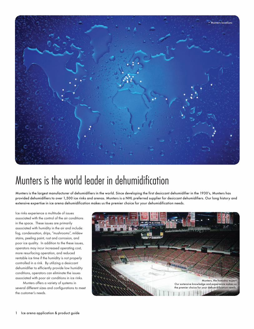
Munters is the world leader in dehumidifi cationMunters is the largest manufacturer of dehumidifiers in the world. Since developing the first desiccant dehumidifier in the 1930’s, Munters has provided dehumidifiers to over 1,500 ice rinks and arenas. Munters is a NHL preferred supplier for desiccant dehumidifiers. Our long history and extensive expertise in ice arena dehumidification makes us the premier choice for your dehumidification needs.
• Munters locations
Ice rinks experience a multitude of issues associated with the control of the air conditions in the space. These issues are primarily associated with humidity in the air and include: fog, condensation, drips, “mushrooms”, mildew stains, peeling paint, rust and corrosion, and poor ice quality. In addition to the these issues, operators may incur increased operating cost, more resurfacing operation, and reduced rentable ice time if the humidity is not properly controlled in a rink. By utilizing a desiccant dehumidifier to efficiently provide low humidity conditions, operators can eliminate the issues associated with poor air conditions in ice rinks. Munters offers a variety of systems in several different sizes and configurations to meet the customer’s needs.
Munters, the humidity expertOur extensive knowledge and experience makes us the premier choice for your dehumidifi cation needs.
Ice arena application & product guide 2
HVAC system designCalculating the dehumidification load and outside air (OA) quantity is the first step in sizing the HVAC system for an ice rink. Since the ice sheet typically provides the entire cooling requirement (approx 30 to 50 tons of cooling effect), the HVAC systems primary function in an ice rink is to dehumidify. The outside air (OA) is the largest dehumidification load for the rink. Outside air is brought into the space to dilute contaminants and maintain IAQ requirements. It is most effective to dehumidify or treat the OA before it enters the building and to use dew point sensor control, not relative humidity control. In addition, by incorporating CO and CO2 sensors or an occupied/unoccupied mode time clock the facility will be able to reduce and monitor the amount of OA being delivered to the space. Since ice rinks require a large outside air quantity and the differential between space condition and outside air condition can be
extreme, energy recovery is often a good enhancement to the dehumidifier. An enthalpy wheel can be added to dehumidification equipment to lower the work required by the active desiccant dehumidification portion of the equipment and provide substantially lower operating costs. Once the equipment has been selected, it needs to be positioned and ductwork sized and arranged. Air distribution is generally routed around the rink, but care should be taken so that supply air does not discharge on to the ice surface as sublimation or melting of the ice is possible. High supply parallel to the floor has worked well with the return at floor level and close to the unit. Units mounted inside require condensation control for specific ductwork system to avoid moisture problems. Outside air duct should be positively drained and insulated to minimize and control condensation inside the ductwork in the summer. Reactivation ductwork for desiccant
systems should be treated the same as outside air ductwork. A reoccurring mistake in facilities with multiple sheets is to utilize common return ductwork from all ice sheets. Supply and return ductwork should be designed so that individual ice sheets can be isolated when they are taken offline for nonuse periods or maintenance. High return conditions will overload the capacity of the dehumidification equipment if return from an offline sheet is allowed to recirculate through the dehumidifier.
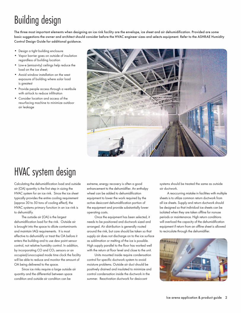
• Design a tight building enclosure• Vapor barrier goes on outside of insulation
regardless of building location• Low-e (emissivity) ceilings help reduce the
load on the ice sheet;• Avoid window installation on the west
exposure of building where solar load is greatest
• Provide people access through a vestibule with airlock to reduce infiltration
• Consider location and access of the resurfacing machine to minimize outdoor air leakage
Building designThe three most important elements when designing an ice rink facility are the envelope, ice sheet and air dehumidification. Provided are some basic suggestions the owner and architect should consider before the HVAC engineer sizes and selects equipment. Refer to the ASHRAE Humidity Control Design Guide for additional guidance.
3 Ice arena application & product guide
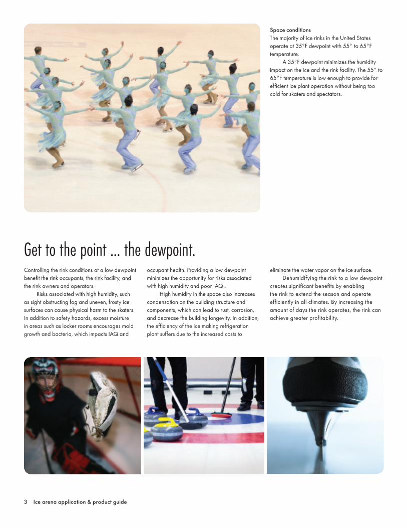
Space conditionsThe majority of ice rinks in the United States operate at 35°F dewpoint with 55° to 65°F temperature. A 35°F dewpoint minimizes the humidity impact on the ice and the rink facility. The 55° to 65°F temperature is low enough to provide for efficient ice plant operation without being too cold for skaters and spectators.
Controlling the rink conditions at a low dewpoint benefit the rink occupants, the rink facility, and the rink owners and operators. Risks associated with high humidity, such as sight obstructing fog and uneven, frosty ice surfaces can cause physical harm to the skaters. In addition to safety hazards, excess moisture in areas such as locker rooms encourages mold growth and bacteria, which impacts IAQ and
occupant health. Providing a low dewpoint minimizes the opportunity for risks associated with high humidity and poor IAQ . High humidity in the space also increases condensation on the building structure and components, which can lead to rust, corrosion, and decrease the building longevity. In addition, the efficiency of the ice making refrigeration plant suffers due to the increased costs to
eliminate the water vapor on the ice surface. Dehumidifying the rink to a low dewpoint creates significant benefits by enabling the rink to extend the season and operate efficiently in all climates. By increasing the amount of days the rink operates, the rink can achieve greater profitability.
Get to the point ... the dewpoint.

Ice arena application & product guide 4
Frequently air is blown into locker rooms from the rink, or exhaust fans are used to migrate air from the rink to the locker rooms. "Rink air" is very expensive to produce and it is not encouraged to release that cool, low dewpoint air for distribution to other areas of the arena. It is more cost efficient to install smaller, separate systems to condition the locker rooms and other common areas. The building load differs greatly depending on the type of occupancy and the quantity of
people in any specific area during that time. For example, after a game a large quantity of people typically crowd the locker room with increased metabolisms and raised temperatures. This type of swing occupancy in a space needs a dedicated system to efficiently control the space conditions and provide healthy IAQ for occupants. If designed properly, the system will contribute to the total building energy savings by cycling off exhaust fans when the space is not occupied to minimize operating costs.
To select a dehumidifierUse the worksheet and formulas below to calculate the total moisture load of your ice arena.
Formulas and conversions
OACFM = Ventilation Air Quantity (cfm)
* Sports arena (play area) = 0.30 cfm/ft2
* Spectator area = 0.06 cfm/ft2 + 7.5 cfm/person
Δ Grains = difference in absolute humidity of the outside air and the indoor space (gr/lb)
Infiltration Leak RateTight 0.1 cfm/ft2
Average 0.3 cfm/ft2
Loose 0.6 cfm/ft2
Convert cfm into lbs/hr using following formula:lbs/hr= 0.000643 x CFM x Δ Grains CFM = Leak Rate X building size (in number 1)
People Load (per person) lbs/hr
Seated at rest 0.10Seated, light work 0.20Moderate Dancing 0.52Light Exercise 0.83Medium Athletic Activity 0.92Athletics 1.04
Internal Load (lbs/hr) = Infiltration + People Load
OA Load (lbs/hr) = humidity load of outside air
*lbs/hr = 0.000643 x OACFM x Δ Grains
* Refer to the "ASHRAE Handbook 2013 Fundamentals" for these conditions** NHL suggests indoor arena conditions be held at a 35˚F dewpoint or 30 grains
A
B
C
D
E
F
1. What is the building size?
2. Maximum occupancy of building?
3. How much outside air (OACFM) is needed? See
+ =
4. Using ASHRAE design dewpoint conditions*, determine the outside air grains.
5. Calculate the delta grains. See
– =
6. Calculate your building's infiltration leak rate? See
7. Calculate the people load. See
8. Calculate the total moisture load (lbs/hr) of the building. See
+ =
(lbs/hr)
(lbs/hr)
total size (ft2)
spectator area (cfm)
internal load (lbs/hr)
outside air grains (Answer from question 4)
play area (cfm)
oa load (lbs/hr)
indoor space grains**
outside air (cfm)
total moisture load
Δ grains
Using the total moisture load, refer to the product dehumidification capacity charts on page 5 and 6 to estimate a suitable equipment size for your arena.
A
B
C
D
E, F, A, B
Locker rooms are the forgotten space
Product descriptionFreeDry™ combines advanced low temperature desiccant technology with refrigeration based technology. Utilizing the benefit of both technologies provides a dehumidifier that can provide and maintain low dewpoint in the space at very low operating cost. In addition, the FreeDry™ system provides lower leaving temperature is the summer to minimize the load on the ice sheet.
5 Ice arena application & product guide
FreeDry™
Features and benefits
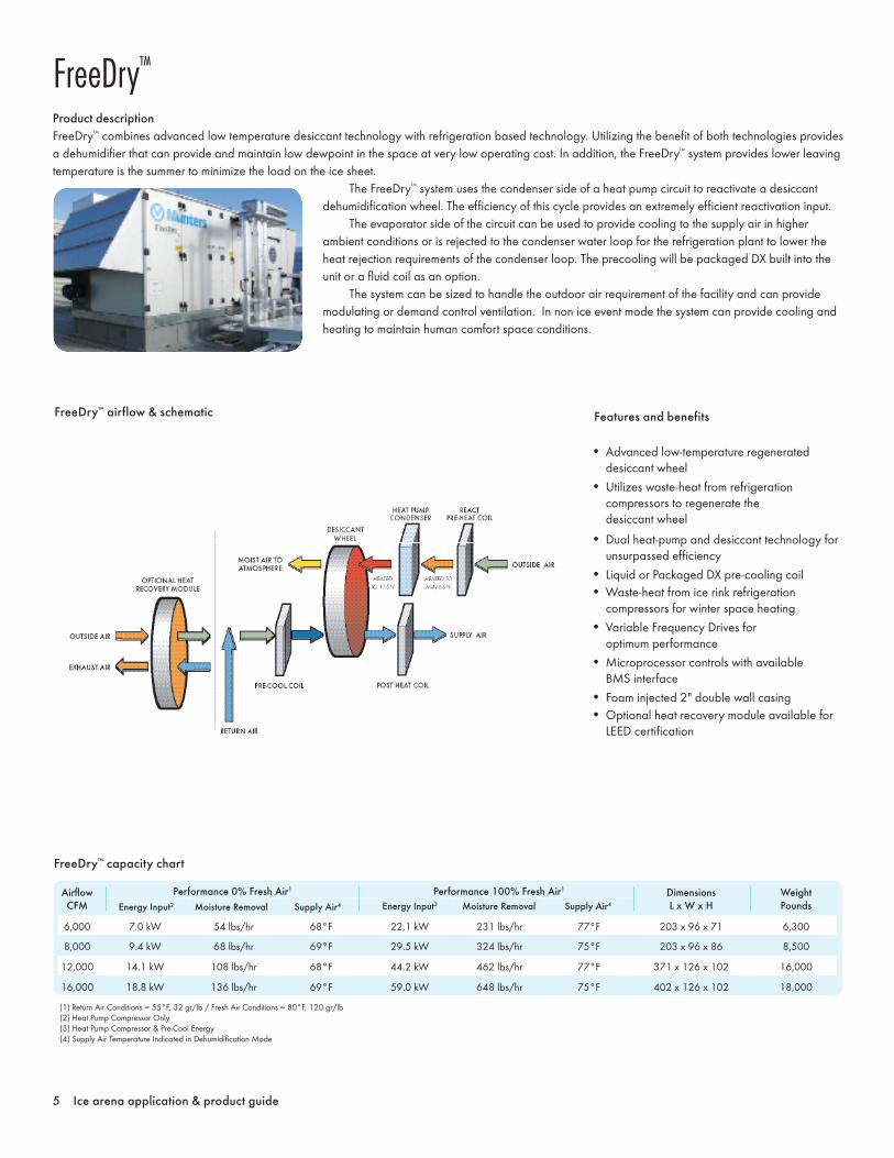
• Advanced low-temperature regenerated desiccant wheel
• Utilizes waste-heat from refrigeration compressors to regenerate the desiccant wheel
• Dual heat-pump and desiccant technology for unsurpassed efficiency
• Liquid or Packaged DX pre-cooling coil• Waste-heat from ice rink refrigeration
compressors for winter space heating• Variable Frequency Drives for
optimum performance• Microprocessor controls with available
BMS interface• Foam injected 2" double wall casing• Optional heat recovery module available for
LEED certification
FreeDry™ airflow & schematic
The FreeDry™ system uses the condenser side of a heat pump circuit to reactivate a desiccant dehumidification wheel. The efficiency of this cycle provides an extremely efficient reactivation input. The evaporator side of the circuit can be used to provide cooling to the supply air in higher ambient conditions or is rejected to the condenser water loop for the refrigeration plant to lower the heat rejection requirements of the condenser loop. The precooling will be packaged DX built into the unit or a fluid coil as an option. The system can be sized to handle the outdoor air requirement of the facility and can provide modulating or demand control ventilation. In non ice event mode the system can provide cooling and heating to maintain human comfort space conditions.
FreeDry™ capacity chart
Airflow CFM
Performance 0% Fresh Air1
Energy Input2 Moisture Removal Supply Air4
Performance 100% Fresh Air1
Energy Input3 Moisture Removal Supply Air4
DimensionsL x W x H
WeightPounds
6,000 7.0 kW 54 lbs/hr 68°F 22.1 kW 231 lbs/hr 77°F 203 x 96 x 71 6,300
8,000 9.4 kW 68 lbs/hr 69°F 29.5 kW 324 lbs/hr 75°F 203 x 96 x 86 8,500
12,000 14.1 kW 108 lbs/hr 68°F 44.2 kW 462 lbs/hr 77°F 371 x 126 x 102 16,000
16,000 18.8 kW 136 lbs/hr 69°F 59.0 kW 648 lbs/hr 75°F 402 x 126 x 102 18,000
(1) Return Air Conditions = 55°F, 32 gr/lb / Fresh Air Conditions = 80°F, 120 gr/lb(2) Heat Pump Compressor Only(3) Heat Pump Compressor & Pre-Cool Energy(4) Supply Air Temperature Indicated in Dehumidification Mode

Product descriptionThe IceAire™ dehumidifier is installed in more ice rink applications than any other dehumidifier. It provides a low cost, low maintenance dehumidifier for the low humidity levels associated with ice rinks. It utilizes a direct fired gas burner or steam to reactivate a desiccant wheel. This allows the air stream to be dried to extremely low levels to provide maximum capacity.
Ice arena application & product guide 6
IceAire™ Desiccant
Features and benefits
• Foam injected 2” double wall casing• High temperature desiccant cycle for low
leaving dewpoints• Optional DDC microprocessor controls• Option for modulating outside air • ETL listed • Optional energy recovery wheel for high
outside air applications• Packaged DX, split system or chilled
water options
IceAire™ DDS airflow & schematic
The system can be configured with optional energy recovery wheel, cooling coils, heating coils and burners, and packaged dx condensing sections. It can be configured to handle up to 100% outside air and can modulate the outside air quantity. The high temperature reactivation allows for the delivery of supply air conditions as low as 10°F dewpoint. The simple direct fired burner reactivation and slow turning desiccant wheel (0.1 RPM) provide a very simple, very reliable dehumidification system. This low leaving air condition provides extremely large capacity in a small airflow and cabinet size.
IceAire™ desiccant capacity chart
Unit OA Maximum CFMReturn
Total Dehumid lbs./hr.*
DimensionsLxWxH
WeightPounds
DDS 20 12,000 12,000 12,000 250 219 x 80 x 70 6,500
DDS 30 24,000 24,000 24,000 300 219 x 96 x 101 8,500
DDS 40 36,000 36,000 36,000 550 280 x 134 x 101 10,500
State No Outside Air With Outside AirPoint CFM ºF gr/lb CFM ºF gr/lb
A Outside Air 0 75 70 2,500 95 120B Return Air 10,000 55 30 7,500 55 30C Post Desiccant Wheel 10,000 83 4 10,000 100 17D Supply Air 10,000 55 4 10,000 60 17
*At 100% OA (95F and 120 gr/lb)
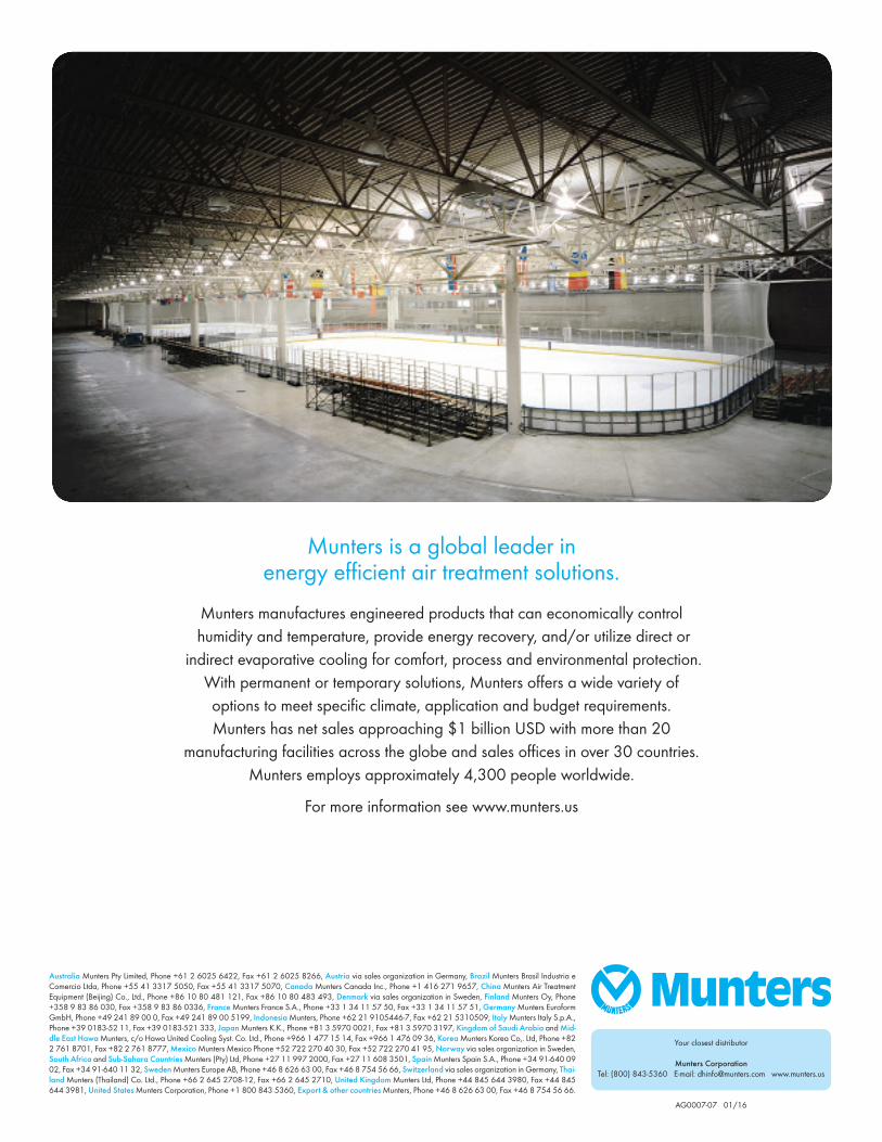
Munters is a global leader in energy efficient air treatment solutions.
Munters manufactures engineered products that can economically control humidity and temperature, provide energy recovery, and/or utilize direct or
indirect evaporative cooling for comfort, process and environmental protection. With permanent or temporary solutions, Munters offers a wide variety of options to meet specific climate, application and budget requirements. Munters has net sales approaching $1 billion USD with more than 20
manufacturing facilities across the globe and sales offices in over 30 countries. Munters employs approximately 4,300 people worldwide.
For more information see www.munters.us
Your closest distributor
Munters Corporation Tel: (800) 843-5360 E-mail: [email protected] www.munters.us
AG0007-07 01/16
Australia Munters Pty Limited, Phone +61 2 6025 6422, Fax +61 2 6025 8266, Austria via sales organization in Germany, Brazil Munters Brasil Industria e Comercio Ltda, Phone +55 41 3317 5050, Fax +55 41 3317 5070, Canada Munters Canada Inc., Phone +1 416 271 9657, China Munters Air Treatment Equipment (Beijing) Co., Ltd., Phone +86 10 80 481 121, Fax +86 10 80 483 493, Denmark via sales organization in Sweden, Finland Munters Oy, Phone +358 9 83 86 030, Fax +358 9 83 86 0336, France Munters France S.A., Phone +33 1 34 11 57 50, Fax +33 1 34 11 57 51, Germany Munters Euroform GmbH, Phone +49 241 89 00 0, Fax +49 241 89 00 5199, Indonesia Munters, Phone +62 21 9105446-7, Fax +62 21 5310509, Italy Munters Italy S.p.A., Phone +39 0183-52 11, Fax +39 0183-521 333, Japan Munters K.K., Phone +81 3 5970 0021, Fax +81 3 5970 3197, Kingdom of Saudi Arabia and Mid-dle East Hawa Munters, c/o Hawa United Cooling Syst. Co. Ltd., Phone +966 1 477 15 14, Fax +966 1 476 09 36, Korea Munters Korea Co,. Ltd, Phone +82 2 761 8701, Fax +82 2 761 8777, Mexico Munters Mexico Phone +52 722 270 40 30, Fax +52 722 270 41 95, Norway via sales organization in Sweden, South Africa and Sub-Sahara Countries Munters (Pty) Ltd, Phone +27 11 997 2000, Fax +27 11 608 3501, Spain Munters Spain S.A., Phone +34 91-640 09 02, Fax +34 91-640 11 32, Sweden Munters Europe AB, Phone +46 8 626 63 00, Fax +46 8 754 56 66, Switzerland via sales organization in Germany, Thai-land Munters (Thailand) Co. Ltd., Phone +66 2 645 2708-12, Fax +66 2 645 2710, United Kingdom Munters Ltd, Phone +44 845 644 3980, Fax +44 845 644 3981, United States Munters Corporation, Phone +1 800 843 5360, Export & other countries Munters, Phone +46 8 626 63 00, Fax +46 8 754 56 66.


