Muon g-2 experiment hall design Final Internship Report Dario Lusso September 25, 2015 Supervisor: Dr. Brendan Casey 1 Introduction: the g-2 experiment The upcoming muon (g - 2) experiment at Fermilab will measure the anoma- lous magnetic moment of the muon to a relative precision of 140 ppb, 4 times better than the previous experiment at Brookhaven National Laboratory. The new experiment is motivated by the persistent 3 - 4 standard devia- tions difference between the experimental value and the Standard Model prediction, and it will have the statistical sensitivity necessary to either re- fute the claim or confirm it with a confidence level exceeding a discovery threshold. The experiment is currently under testing and scheduled to start running in 2017. The first step of the experiment was moving the 14 meters diameter magnet from BNL to FNAL, giving it a new home in the newly built muon campus. The move took 35 days during summer 2013 and traversed 3,200 miles over land and sea. The ring was transported out of BNL using a specially adapted flatbed truck and a 45-ton metal apparatus keeping the electromagnet as flat as possible. A massive crane was then used to move it from the truck onto a waiting barge. The barge spent nearly a month traveling down the east coast, around the tip of Florida, into the Gulf of Mexico and then up the Mississippi, Illinois and Des Plaines rivers. When the barge arrived in Lemont, Illinois, the ring was moved to the truck again. And then over three consecutive nights that truck was used to drive the ring to Fermilab in Batavia. More than 3000 people welcomed its arrival at Fermilab, marking the beginning of an experiment that will lead to important discoveries. 1
Transcript
Muon g-2 experiment hall design
Final Internship Report
Dario Lusso
September 25, 2015
Supervisor: Dr. Brendan Casey
1 Introduction: the g-2 experiment
The upcoming muon (g - 2) experiment at Fermilab will measure the anoma-lous magnetic moment of the muon to a relative precision of 140 ppb, 4 timesbetter than the previous experiment at Brookhaven National Laboratory.The new experiment is motivated by the persistent 3 - 4 standard devia-tions difference between the experimental value and the Standard Modelprediction, and it will have the statistical sensitivity necessary to either re-fute the claim or confirm it with a confidence level exceeding a discoverythreshold. The experiment is currently under testing and scheduled to startrunning in 2017.The first step of the experiment was moving the 14 meters diameter magnetfrom BNL to FNAL, giving it a new home in the newly built muon campus.The move took 35 days during summer 2013 and traversed 3,200 miles overland and sea. The ring was transported out of BNL using a specially adaptedflatbed truck and a 45-ton metal apparatus keeping the electromagnet asflat as possible. A massive crane was then used to move it from the truckonto a waiting barge. The barge spent nearly a month traveling down theeast coast, around the tip of Florida, into the Gulf of Mexico and then upthe Mississippi, Illinois and Des Plaines rivers. When the barge arrived inLemont, Illinois, the ring was moved to the truck again. And then overthree consecutive nights that truck was used to drive the ring to Fermilab inBatavia. More than 3000 people welcomed its arrival at Fermilab, markingthe beginning of an experiment that will lead to important discoveries.
1
(a) The magnet arriving at Fermilab. (b) Travel map.
Figure 1: The magnet traveled more than 3000 miles in a month long jour-ney.
2 Experiment hall
As of September 2015, the experiment design phase is approaching the end,the majority of the instruments and equipment that are required were al-ready established and so is the layout of the main elements. It is time tobegin testing, consequently, a 3D model of the experiment hall is needed tocheck if the design is feasible and to assist the technicians who will actuallyput everything in place.When the experiment will be ready to run, the room, and so the model, willcontain:
• the 14 meters magnet
• the beam chamber
• the straw trackers 1
• 24 calorimeters
• trolley garage and drive
• vacuum pumps 1
• fiber harp monitors
• injection kickers 1
2
• hall features such as the catwalk and the stairs
• the fake floor
• cable trays and racks for the electronics.
Figure 2: The experiment hall on 09/21/2015.
During the construction of the model, mainly two real-world constraints werekept in mind. The first one is obviously the limited amount of space insidethe 14 meters ring, that forced to position as many items as possible onthe outside. The second one is the magnetic flux density sensitivity of someinstruments, like vacuum pumps, which had to be positioned accordingly. Inthe following sections, we will examine the main components in more detail.
2.1 Model structure
The model was built using Siemens NX 9.0, on of the most widespread high-end CAD software, that is adopted by Fermilab for its integration with PLMplatform TeamCenter.Up to now, the model includes more than 100 elements and they are orga-nized as follows. The room and the parts referenced to it, like the catwalkand the stairs, are modeled directly inside the main assembly part. The
1These items, or some of these items, are still to be included in the model
3
ring is a subassembly and is added to the main part. It includes the beamchamber, which is another subassembly itself, and most of the equipmentand features attached. Finally, the floor, the racks and all the other itemsare added to main assembly as single components.Most of the items were modeled starting from technical drawings or blueprints.Drawings were not always available or, as we found out, sometimes wereinaccurate. In those cases, we obtained the dimensions for the model bymeasuring the real features. Consequently, measurement errors were intro-duced in the model, slightly decreasing the overall precision and limiting thepossibility of using the model as reference for mounting real components.
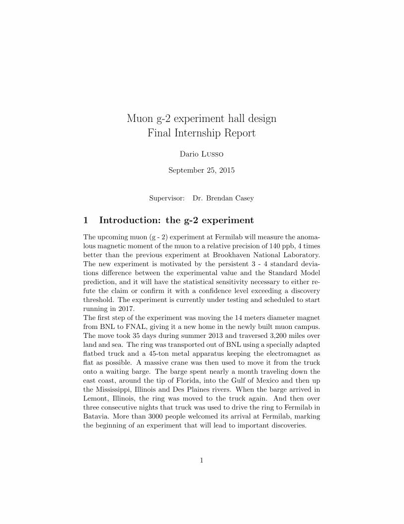
3 Ring
Figure 3: The main ring.
The ring is of course the main equipment needed for the g-2 experiment. Itis 14 meters in diameter and it has a C-profile to accommodate the beamchamber. It also holds two superconducting magnets, that need to be cooledto superconducting temperatures and insulated, to generate the magneticfield. Insulation is provided by vacuum, which is pulled by pumps locatedradially around the ring. The system is cooled by flowing liquid helium. The1.45T magnetic field is responsible for directing the muon beam, comingfrom the muon source, along its circular path. The ring is held in place by12 adjustable concrete supports, to compensate the floor irregularities andkeep the ring flat.
4
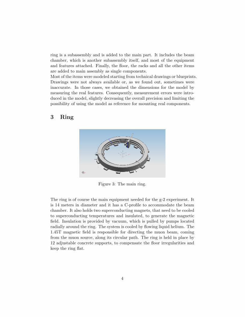
Figure 4: Port map of the ring.
4 Beam Chamber
The beam chamber ring is the second important component of the exper-iment. It is made of 12 different sections, almost each of those having aslightly different structure to be apt for different purposes. All the cham-bers have the same angular dimension, spanning 30 degrees, to form a ring.Every chamber is positioned exactly on the yoke between two supportingblocks. The beam chamber ring is referenced from the Chamber 1, whichcarries the beam inlet. The chambers also need to be airtight because vac-uum will be pulled inside the beam chamber. Thus, they are connectedwith gaskets to ensure a perfect seal even if the shape is not ideal. Finally,a rail system will be mounted inside all the chambers to enable the trolleyoperation.The chamber differences are related to the instrument connected to theirports. The port map of the ring is shown in Figure 4.
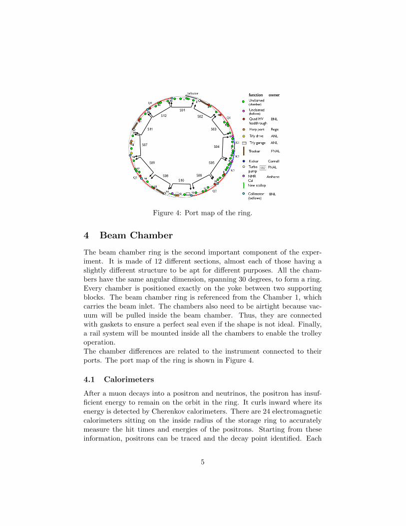
4.1 Calorimeters
After a muon decays into a positron and neutrinos, the positron has insuf-ficient energy to remain on the orbit in the ring. It curls inward where itsenergy is detected by Cherenkov calorimeters. There are 24 electromagneticcalorimeters sitting on the inside radius of the storage ring to accuratelymeasure the hit times and energies of the positrons. Starting from theseinformation, positrons can be traced and the decay point identified. Each
5
Figure 5: One of the calorimeters, coupled to a vacuum chamber.
calorimeter needs two rails to move towards the chamber and back, whichneed to be precisely lined up with the scallops on the vacuum chambers.The rails are orthogonal to the ring circumference, but due to the presenceof the fake floor, some of them need a special position, at a larger radius, toavoid interference. In Figure 5, a calorimeter is shown in contact with thevacuum chamber. The calorimeter model, as can be seen, is very detailedand made of many components. Only a couple of calorimeters are presentin the final assembly model, to keep it simple and manageable by a laptopcomputer.
4.2 Fake floor
A fake floor will be positioned to cover the cables and wirings needed forthe instruments operating close to the beam chamber. It will be a 26 feetsquare, centered on the alignment monument, with cut corners to allow thepositioning of items on the real ground. Several racks for the electronics ofthe different instruments will be positioned on top of it to be easily accessibleby the operators.Figure 9b shows the actual fake floor being put in place. In particular, wewere interested in marking on the floor where each one of the supports willsit to keep the space free from other items and to properly design the cabletrays going under the floor.
6
(a) Floor layout. (b) Mounting the fake floor.
Figure 6: The fake floor covers cables and wirings.
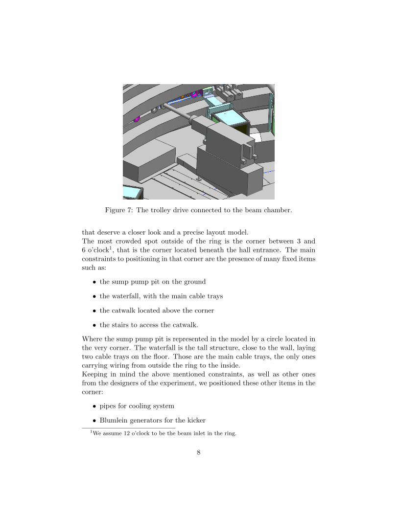
4.3 Trolley equipment
As we mentioned earlier, the experiment requires two trolleys traveling insidethe beam chamber on the rail system. Both trolleys are about 20 incheslong and have a similar tubular shape. The first trolley is for maintenanceand calibration. It will quantify the displacement of the Straw Detectorsin order to calibrate them and will detect the warping of the walls of thevacuum chambers. It will carry a camera and other sensors and it’s stillbeing designed. The second one will mount 17 NMR probes and will beable to measure the magnetic field at 6000 locations along the ring over thecourse of one hour.A drive mechanism with cables in order will run the trolley around the ringduring dedicated measurement periods. The drive mechanism is bulky andwill be located inside of the ring.The last part of trolley equipment is the garage. The garage houses the trol-ley in a remote location during muon injection and provides the mechanismto move the trolley into the storage area for the NMR measurement.
5 Outside the ring
Up to now, we have only considered the inside part of the ring. That isbecause it is going to be the most critical and crowded with items, butstill needs to be accessible by operators. On the other hand, most of theareas outside the ring can fit the equipment without problems, so, being lowpriority, they were not modeled in detail. There are a few spots, though,
7
Figure 7: The trolley drive connected to the beam chamber.
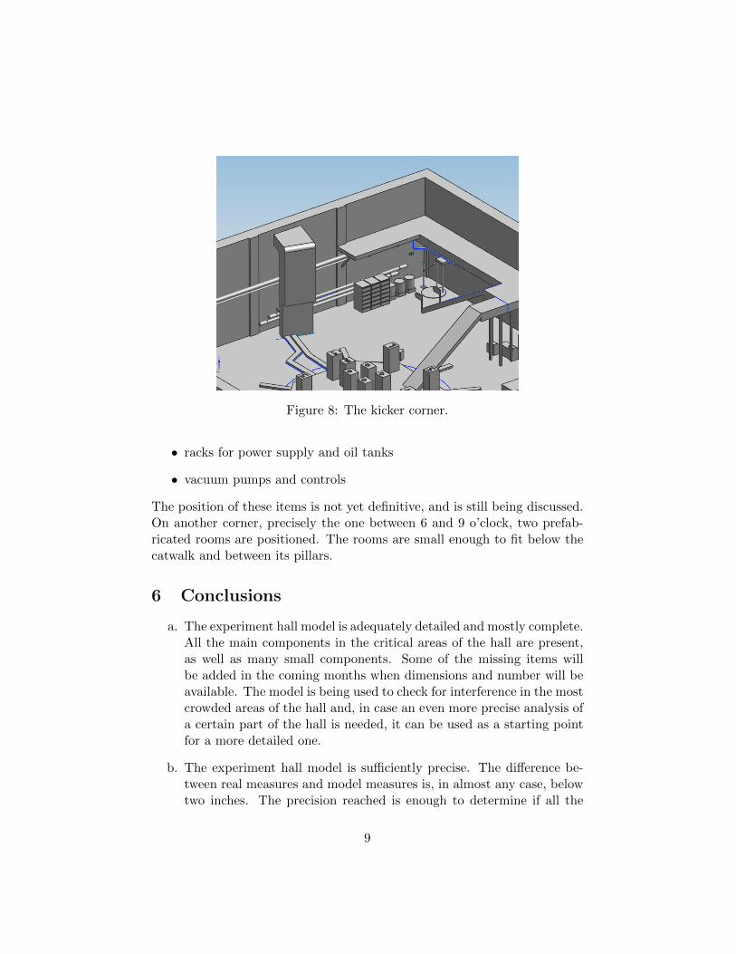
that deserve a closer look and a precise layout model.The most crowded spot outside of the ring is the corner between 3 and6 o’clock1, that is the corner located beneath the hall entrance. The mainconstraints to positioning in that corner are the presence of many fixed itemssuch as:
• the sump pump pit on the ground
• the waterfall, with the main cable trays
• the catwalk located above the corner
• the stairs to access the catwalk.
Where the sump pump pit is represented in the model by a circle located inthe very corner. The waterfall is the tall structure, close to the wall, layingtwo cable trays on the floor. Those are the main cable trays, the only onescarrying wiring from outside the ring to the inside.Keeping in mind the above mentioned constraints, as well as other onesfrom the designers of the experiment, we positioned these other items in thecorner:
• pipes for cooling system
• Blumlein generators for the kicker
1We assume 12 o’clock to be the beam inlet in the ring.
8
Figure 8: The kicker corner.
• racks for power supply and oil tanks
• vacuum pumps and controls
The position of these items is not yet definitive, and is still being discussed.On another corner, precisely the one between 6 and 9 o’clock, two prefab-ricated rooms are positioned. The rooms are small enough to fit below thecatwalk and between its pillars.
6 Conclusions
a. The experiment hall model is adequately detailed and mostly complete.All the main components in the critical areas of the hall are present,as well as many small components. Some of the missing items willbe added in the coming months when dimensions and number will beavailable. The model is being used to check for interference in the mostcrowded areas of the hall and, in case an even more precise analysis ofa certain part of the hall is needed, it can be used as a starting pointfor a more detailed one.
b. The experiment hall model is sufficiently precise. The difference be-tween real measures and model measures is, in almost any case, belowtwo inches. The precision reached is enough to determine if all the
9
pieces of equipment needed for the experiment can fit inside the hall,while it may not be a good enough reference for the actual positioning.
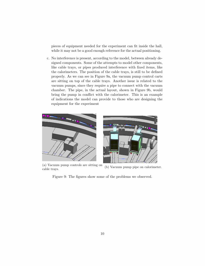
c. No interference is present, according to the model, between already de-signed components. Some of the attempts to model other components,like cable trays, or pipes produced interference with fixed items, likethe calorimeters. The position of the cable trays, is still to be definedproperly. As we can see in Figure 9a, the vacuum pump control cartsare sitting on top of the cable trays. Another issue is related to thevacuum pumps, since they require a pipe to connect with the vacuumchamber. The pipe, in the actual layout, shown in Figure 9b, wouldbring the pump in conflict with the calorimeter. This is an exampleof indications the model can provide to those who are designing theequipment for the experiment
(a) Vacuum pump controls are sitting oncable trays.
(b) Vacuum pump pipe on calorimeter.
Figure 9: The figures show some of the problems we observed.