33
Murelle installation and servicing instructions GB

Murelle
installation and servicing instructionsGB

CONTENTS
1 TECHNICAL FEATURES AND DIMENSIONS
1.1 DESCRIPTION OF BOILER . . . . . . . . . . . . . . . . . . . . . . . . . . . . . . . . . . . . . . . . . . . . . . . . . 11.2 DIMENSIONS1.3 TECHNICAL FEATURES . . . . . . . . . . . . . . . . . . . . . . . . . . . . . . . . . . . . . . . . . . . . . . . . . . . 21.4 FUNCTIONAL DIAGRAM . . . . . . . . . . . . . . . . . . . . . . . . . . . . . . . . . . . . . . . . . . . . . . . . . . 31.5 INTERNAL VIEW . . . . . . . . . . . . . . . . . . . . . . . . . . . . . . . . . . . . . . . . . . . . . . . . . . . . . . . . . 41.6 SYSTEM AVAILABLE HEAD . . . . . . . . . . . . . . . . . . . . . . . . . . . . . . . . . . . . . . . . . . . . . . . . 5
2 GENERAL REQUIREMENTS FOR INSTALLATION
2.1 BOILER ROOM . . . . . . . . . . . . . . . . . . . . . . . . . . . . . . . . . . . . . . . . . . . . . . . . . . . . . . . . . . 62.2 VENTILATION OF BOILER ROOM FOR “MURELLE” BOILERS2.3 CONNECTING UP SYSTEM2.4 WALL-MOUNTING PLATE2.5 CONNECTING UP “MURELLE” FLUE . . . . . . . . . . . . . . . . . . . . . . . . . . . . . . . . . . . . . . . . . 72.6 “MURELLE BF” COAXIAL AIR INLET-FLUE OUTLET ASSEMBLY . . . . . . . . . . . . . . . . . . . 82.7 “MURELLE BF” SEPARATE AIR INLET-FLUE OUTLET PIPES . . . . . . . . . . . . . . . . . . . . . . 102.8 CHARACTERISTICS OF FEEDWATER . . . . . . . . . . . . . . . . . . . . . . . . . . . . . . . . . . . . . . . . 132.9 WATER FAILURE SAFETY DEVICE2.10 SYSTEM FILLING2.11 “MURELLE 20 TX CE IONO” BOILER SUPPLY . . . . . . . . . . . . . . . . . . . . . . . . . . . . . . . . . . 142.12 ELECTRICAL CONNECTION . . . . . . . . . . . . . . . . . . . . . . . . . . . . . . . . . . . . . . . . . . . . . . . 152.13 ELECTRONIC BOARD . . . . . . . . . . . . . . . . . . . . . . . . . . . . . . . . . . . . . . . . . . . . . . . . . . . . 192.14 TEMPERATURE SENSORS . . . . . . . . . . . . . . . . . . . . . . . . . . . . . . . . . . . . . . . . . . . . . . . . . 202.15 ELECTRONIC IGNITION2.16 INTERRUPTION OF THE THERMOCOUPLE . . . . . . . . . . . . . . . . . . . . . . . . . . . . . . . . . . . 212.17 SMOKE SAFETY DEVICE2.18 SMOKE PRESSURE SWITCH2.19 DISASSEMBLY OF OUTER CASING . . . . . . . . . . . . . . . . . . . . . . . . . . . . . . . . . . . . . . . . . . 22
3 USE AND MAINTENANCE
3.1 PRELIMINARY CHECKS ON IGNITION . . . . . . . . . . . . . . . . . . . . . . . . . . . . . . . . . . . . . . . 233.2 DISASSEMBLY OF EXPANSION VESSEL3.3 GAS VALVE . . . . . . . . . . . . . . . . . . . . . . . . . . . . . . . . . . . . . . . . . . . . . . . . . . . . . . . . . . . . . 243.4 GAS VALVE ADJUSTMENT3.5 ADJUSTMENT OF HEAT OUTPUT FOR HEATING . . . . . . . . . . . . . . . . . . . . . . . . . . . . . . . 263.6 PILOT BURNER ADJUSTMENT3.7 CONVERSION TO DIFFERENT GAS3.8 FILTER ON GAS PIPE . . . . . . . . . . . . . . . . . . . . . . . . . . . . . . . . . . . . . . . . . . . . . . . . . . . . . 273.9 CLEANING AND MAINTENANCE3.10 FAULT FINDING . . . . . . . . . . . . . . . . . . . . . . . . . . . . . . . . . . . . . . . . . . . . . . . . . . . . . . . . . 28

1
1 Technical features and dimensions
1.2 DIMENSIONS
Fig. 1
1.2.1 “MURELLE” version
1.2.1 “MURELLE BF” version
CONNECTIONSR C.H. return 3/4”M C.H. flow 3/4”G Gas connection 3/4”E Domestic water inlet 1/2”U Domestic water outlet 1/2”
20 25A ø mm 130 150L mm 450 500
CONNECTIONSR C.H. return 3/4”M C.H. flow 3/4”G Gas connection 3/4”E Domestic water inlet 1/2”U Domestic water outlet 1/2”
1.1 DESCRIPTION OF BOILER
“MURELLE - MURELLE BF” boilers are gas-fired ther-mal appliances for central heating and D.H.W. produc-tion. They are equipped with all safety and control devi-ces required by the law and their technical and operatingfeatures meet the requirements of the specifications onthe safety and use of combustible gas. In addition, theyare designed and built in accordance with the EuropeanDirectives EN 297 - EN 483.These appliances can be fired by natural gas (methane)and butane gas (G30) or propane gas (G31). This book-let provides instructions for the following boiler models:– “MURELLE 20 R CE IONO” with electronic ignition
and modulation (central heating only);– “MURELLE 20 CE” with electronic modulation;
– “MURELLE 20 TX CE IONO” with electronic ignitionand modulation, forced draught;
– “MURELLE 20 CE IONO - 25 CE IONO” with electronicignition and modulation;
– “MURELLE 20 BFR CE IONO” with electronic ignitionand modulation (central heating only), forced-draughtsealed-room;
– “MURELLE 20 BF CE” with electronic modulation, for-ced-draught sealed-room;
– “MURELLE 20 BF CE IONO - 25 BF CE IONO” withelectronic ignition and modulation, forced-draughtsealed-room.
The instructions given in this manual are provided for theinstaller to ensure proper installation and perfect opera-tion of the appliance.
20 BF 25 BFL mm 130 150B mm 450 500
Fig. 1/a

Power Smokes Smokes D.H.W. D.H.W. flow rate Minimum D.H.W. pressureBOILER MODEL consumption temperature flow Heat Output ∆t 30°C D.H.W. flow rate Min. Max.
°C gr/s kW I/min I/min bar bar
MURELLE 20 105 (150 vers. TX) 100 24.7 23.3 11.0 2 0.5 7
MURELLE 25 120 100 29.4 27.6 12.9 2 0.5 7
MURELLE 20 BF 150 136 17.2 23.3 11.0 2 0.5 7
MURELLE 25 BF 160 136 22.8 29.6 12.9 2 0.5 7
TABLE 2
Main burner nozzles Pilot injector Gas consumption (*)BOILER MODEL Quantity Natural gas G30-G31 Natural gas G30-G31 Natural gas L.P.G. G30 L.P.G. G31
N° ø mm ø mm ø mm ø mm m3/h kg/h kg/h
MURELLE 20 13 1.30 0.75 0.25 0.20 2.72 2.02 1.99
MURELLE 25 15 1.30 0.77 - - 3.23 2.41 2.37
MURELLE 20 BF 13 1.30 0.75 0.27 0.20 2.72 2.02 1.99
MURELLE 25 BF 15 1.30 0.77 - - 3.47 2.58 2.54
1.3 TECHNICAL FEATURES
Heat Output Heat Input Electr. protection Maximum Expans. vessel Expans. vessel WeightBOILER MODEL (adjustable) (adjustable) grade water head contents preloading
kW kW W bar l bar Kg
MURELLE 20 9.3 ÷ 23.3 10.8 ÷ 25.7 – 3 7 1 40
MURELLE 25 11.6 ÷ 27.6 13.5 ÷ 30.6 – 3 7 1 48
MURELLE 20 BF 9.3 ÷ 23.3 10.8 ÷ 25.7 IP 44 3 7 1 48
MURELLE 25 BF 15.1 ÷ 29.6 18.0 ÷ 32.8 IP 44 3 7 1 54
TABLE 1
TABLE 3
Burner gas pressure Gas supply pressureBOILER MODEL Natural gas L.P.G. (G30) L.P.G. (G31) Natural gas L.P.G. (G30) L.P.G. (G31)
mbar mbar mbar mbar mbar mbar
MURELLE 20-20 BF 10 28 35 20 30 37
MURELLE 25-25 BF 11 28 35 20 30 37
TABLE 4
NOTE: The burner header gas pressure and inputs shown in the table refer to the boiler max. capacity. These values must be kept toin the D.H.W. production.
2
(*) The gas consumptions refer to the calorific value at standard conditions at 15°C - 1013 mbar

1.4 FUNCTIONAL DIAGRAM
1.4.1 “MURELLE” model
3
KEY1 Smoke chamber2 85°C limit stat3 Water-gas exchanger4 Combustion chamber5 Pressure switch valve6 Water pressure switch7 Expansion vessel8 D.H.W. exchanger9 D.H.W. sensor
10 Gas valve11 Hydrometer12 Safety valve13 Filling unit14 Boiler discharge15 Circulation pump16 Heating flow sensor17 100°C safety stat18 Air relief valve19 Air separator20 Antifreeze stat (optional)21 Gas cock (optional)22 Domestic water cock (optional)23 Fixing jig (optional)
1.4.2 “MURELLE BF” model
KEY1 Fan2 85°C limit stat3 Water-gas exchanger4 Combustion chamber5 Pressure switch valve6 Water pressure switch7 Expansion vessel8 D.H.W. exchanger9 D.H.W. sensor
10 Gas valve11 Hydrometer12 Safety valve13 Filling unit14 Boiler discharge15 Circulation pump16 Heating flow sensor17 100°C safety stat18 100°C safety stat (“IONO” versions)19 Air relief valve20 Air separator21 Antifreeze stat (optional)22 Gas cock (optional)23 Domestic water cock (optional)24 Fixing jig (optional)
Fig. 2
Fig. 2/a

4
1.5 INTERNAL VIEW
1.5.1 “MURELLE” model
KEY1 Water pressure switch2 D.H.W. sensor3 D.H.W exchanger4 Burner pressure inlet5 Combustion chamber6 85°C limit stat7 Smoke capillary thermostat8 Air relief valve9 Water-gas exchanger
10 Heating flow sensor11 100°C safety stat12 Pilot burner13 Gas valve14 Circulation pump15 Pressure switch valve
1.5.2 “MURELLE BF” model
KEY1 Water pressure switch2 D.H.W. sensor3 D.H.W. exchanger4 Blocking hinge5 Pilot burner6 Water-gas exchanger7 85°C limit stat8 Fan9 Smoke pressure switch
10 Pressure intake (positive)11 Pressure intake (negative)12 100°C safety stat13 Sealed chamber14 Combustion chamber15 Heating flow sensor16 100°C safety stat (“IONO” versions)17 Burner manifold18 Gas valve19 Circulation pump20 Pressure switch valve
Fig. 3
Fig. 3/a

5
500 1000 15000
100
200
300
400
500
Portata l/h
600
20 25
1.6 SYSTEM AVAILABLE HEAD
RE
SID
UA
LH
EA
D (
mba
r)
FLOW RATE l/h
Fig. 4

6
The boiler should be installed in a fixed location andshall be carried out only by specialized and qualifiedfirms in compliance with all instructions contained in thismanual.
2.1 BOILER ROOM
The “MURELLE” version boilers may be installed in ade-quately ventilated domestic rooms.The “MURELLE BF” version boilers may instead beinstalled, without any constraints regarding location orsupply of air for combustion, in any domestic rooms.
2.2 VENTILATION OF BOILER ROOM FOR “MURELLE” BOILERS
It is essential that in rooms where open-flue gas applian-ces are installed at least as much air can arrive as requi-red by normal combustion of the gas consumed by thevarious appliances. Consequently, it is necessary tomake openings in the walls for entry of air into the rooms. These openings must meet the following requirements:– have a total free section of at least 6 cm2 for every kW
of heat input, with a minimum of 100 cm2 (such ope-nings may possibly be obtained by widening the gapbetween the door and the floor);
– be situated towards the bottom of an external wall,preferably opposite the one in which the burnt gasesoutlet is located.
2.3 CONNECTING UP SYSTEM
Before proceeding to connect up the boiler, you arerecommended to get air to circulate in the piping in orderto eliminate any foreign bodies that might be detrimentalto the operating efficiency of the appliance. Whenmaking the hydraulic connections, make sure that thedimensions indicated in Figs. 1 - 1/a are respected.If the connections supplied with the fixing jig are not usedfor connecting up the pipes to the boiler, steel flexiblepipes must be used so as to avoid any stress being exer-ted on the appliance.In any case a shutoff valve must be mounted on thewashing-water intake piping. The discharge pipe of the safety valve (12 figs. 2 - 2/a)must be connected to a collector funnel for channel-ling away any discharge in the case of the safetyvalve going into action.The gas connection must be made using seamless steelpipe (Mannesmann type), galvanized and with threadedjoints provided with gaskets, excluding three-piece con-nections, except for initial and end connections.Where the piping has to pass through walls, a suitableinsulating sleeve must be provided. When sizing gaspiping, from the meter to the boiler, take into accountboth the volume flow rates (consumption) in m3/h and therelative density of the gas in question. The sections of thepiping making up the system must be such as to gua-rantee a supply of gas sufficient to cover the maximumdemand, limiting pressure loss between the gas meterand any apparatus being used to not greater than:– 1.0 mbar for family II gases (Natural gas)– 2.0 mbar for family III gases (L.P.G.).
An adhesive data plate is stuck on the inside of the frontpanel; it contains all the technical data identifying the boi-ler and the type of gas for which the boiler is arranged.
2.4 WALL-MOUNTING PLATE
The wall-mounting plate is supplied along with the boilerin cardboard packaging, and consists of two plates, witha connecting strip and the corresponding fixing screws(Fig. 5).For assembly, proceed as follows:– fasten the connecting strip to the top plate A and the
bottom plate B;– once the template has been put together, fasten the
plate A on the wall with the two hexagonal-headanchor bolts provided. The connecting strip will auto-matically set the bottom plate B in position;
– use a spirit level to check that the bottom plate B isperfectly horizontal, so as to achieve proper positio-ning and reference for laying all the water and gaspipes in place;
– attach the small bent tube connections or the connec-tion cocks supplied in a kit (optional);
– finally, by means of the two hex screws of the top plateA, make the necessary adjustments to achieve perfectvertical positioning of the boiler.
For the “MURELLE” BF versions, make a hole in the wallsufficiently large to allow for insertion of a 130 mm ø PVCpipe of the same length as the thickness of the wall it hasto pass through. Then fix the PVC pipe in place usingcement mortar. The purpose of the PVC pipe is to facili-tate insertion of the coaxial air-intake flue-dischargeassembly with its corresponding external gasket, asdescribed in Section 2.6.1.
2 General requirements for installation
Fig. 5
7
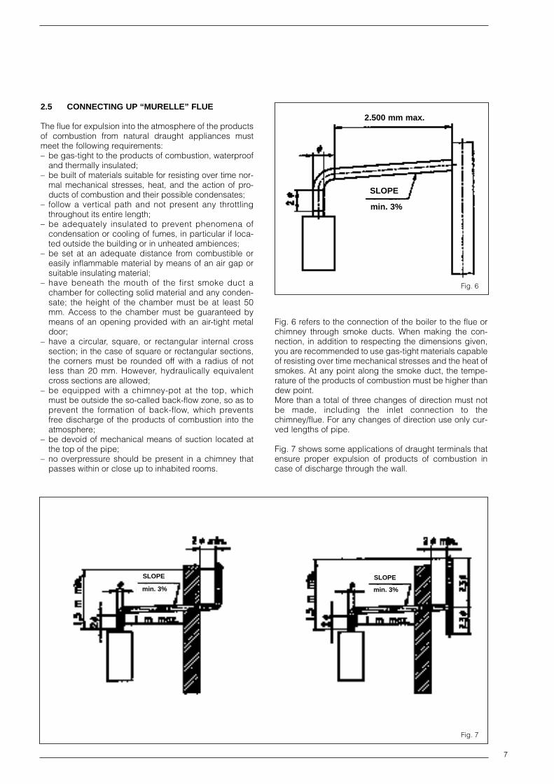
2.5 CONNECTING UP “MURELLE” FLUE
The flue for expulsion into the atmosphere of the productsof combustion from natural draught appliances mustmeet the following requirements:– be gas-tight to the products of combustion, waterproof
and thermally insulated;– be built of materials suitable for resisting over time nor-
mal mechanical stresses, heat, and the action of pro-ducts of combustion and their possible condensates;
– follow a vertical path and not present any throttlingthroughout its entire length;
– be adequately insulated to prevent phenomena ofcondensation or cooling of fumes, in particular if loca-ted outside the building or in unheated ambiences;
– be set at an adequate distance from combustible oreasily inflammable material by means of an air gap orsuitable insulating material;
– have beneath the mouth of the first smoke duct achamber for collecting solid material and any conden-sate; the height of the chamber must be at least 50mm. Access to the chamber must be guaranteed bymeans of an opening provided with an air-tight metaldoor;
– have a circular, square, or rectangular internal crosssection; in the case of square or rectangular sections,the corners must be rounded off with a radius of notless than 20 mm. However, hydraulically equivalentcross sections are allowed;
– be equipped with a chimney-pot at the top, whichmust be outside the so-called back-flow zone, so as toprevent the formation of back-flow, which preventsfree discharge of the products of combustion into theatmosphere;
– be devoid of mechanical means of suction located atthe top of the pipe;
– no overpressure should be present in a chimney thatpasses within or close up to inhabited rooms.
Fig. 6 refers to the connection of the boiler to the flue orchimney through smoke ducts. When making the con-nection, in addition to respecting the dimensions given,you are recommended to use gas-tight materials capableof resisting over time mechanical stresses and the heat ofsmokes. At any point along the smoke duct, the tempe-rature of the products of combustion must be higher thandew point. More than a total of three changes of direction must notbe made, including the inlet connection to thechimney/flue. For any changes of direction use only cur-ved lengths of pipe.
Fig. 7 shows some applications of draught terminals thatensure proper expulsion of products of combustion incase of discharge through the wall.
SLOPE
min. 3%
2.500 mm max.
SLOPE
min. 3%
SLOPE
min. 3%
Fig. 6
Fig. 7

2.6 “MURELLE BF” COAXIAL AIR INLET-FLUEOUTLET ASSEMBLY
The air inlet-flue outlet assembly is supplied apart (optio-nal) in a kit (Code 8084802). It includes:– coaxial duct ø 60/100, length 840, with wind-proof
(anti-blowback) head already fixed to the flue dischar-ge duct;
– pipe bend ø 60/100 with fixing screws;– fixing clamp;– rubber ring nut for external closing;– sponge-rubber gasket.
2.6.1 Assembly of the coaxial duct kit
For assembly follow closely what is indicated in Fig. 8.– Make a hole in the wall sufficiently large to allow for
insertion of a 130 mm ø PVC pipe of the same lengthas the thickness of the wall it has to pass through.Then fix the PVC pipe in place using cement mortar.
WARNING: When cutting the pipe, remember thatthe 60 mm ø flue discharge pipe must be approx.25 mm longer than the air intake tube.
– Before sliding the pipe into the hole made in the wall,insert the rubber sealing ring (E) into its seat made inthe tube.
– Push the tube outwards until the gasket comes out. Pullthe pipe inwards bringing the ring to rest on the wall.
– Slide the inner ring (D) and the metal collar (I) onto thepipe.
– Push the flue discharge duct (F) fully home in the bendand fasten the metal collar (I) in position, tightening thetwo fixing screws.
– Fasten the duct (C) by tightening the two screws (H) onthe aluminium ring nut (D).
NOTE: The air intake-flue outlet assembly must slopegently downwards to prevent rain water getting intothe boiler.
2.6.2 Coaxial air intake-flue outlet assembly accessories
In addition to the coaxial duct kit, also the following canbe supplied on request (Fig. 9):– Extension ø 60/100, length 855 (Code 8084800)– Supplementary 90° pipe elbow ø 60/100 (Code
8085600)– Vertical extension ø 60/100, length 590 (Code 8086900).
NOTE: With the pipe bend supplied in the kit, the maxi-mum length of piping should not exceed 3 metres. Inthe case where the supplementary bend (4) is used, thetotal length of piping can reach a maximum of 1.6 m.When the vertical extension (3) is used, the terminalpart of the pipe must always come out horizontally .
8
KEY1 Coaxial duct kit2 Extension L. 8553 Vertical extension L. 5904 90° supplementary elbow
Fig. 8
Fig. 9
KEYA Elbow flangeB Junction collarC Outer ductD Aluminium ringE Rubber sealing ringF Inner duct c/w terminalH Fixing screwI Protective metal collarJ Inner “O” ring

9
2.6.3 Positioning the outlet terminals
The outlet terminals for forced-draught appliances maybe located in the external perimeter walls of the building.To provide some indications of possible solutions, Table5 gives the minimum distances to be observed, with refe-rence to the type of building shown in Fig. 10.
Notes
1) Terminals below a practicable balcony must be loca-ted in such a way that the total path of the smoke fromits outlet point from the terminal to its outlet point fromthe external perimeter of the balcony, including theheight of possible railings, is not less than 2000 mm.
2) When siting terminals, where materials that may besubject to the action of the products of combustionare present in the vicinity, e.g., eaves, gutters anddownspouts painted or made of plastic material,projecting timberwork, etc., distances of not less than1500 mm must be adopted, unless adequate shiel-ding is provided to guard these materials.
2.6.4 Coaxial duct outlet on roof
To install this type of arrangement, the following are avai-lable as optionals:– roof outlet terminal ø 60/100, length 1280 (Code
8091200);– articulated-joint roof tile (Code 8091300);– extension ø 60/100, length 855 (Code 8084804);– supplementary 90° elbow ø 60/100 (Code 8085601);– vertical extension ø 60/100, length 200 (Code 8086903).When assembling the accessories, remember that theroof discharge terminal (length 1280 mm) cannot beshortened and that the articulated joint of the roof tileallows roof pitches of between 25 ° and 45°.The tile is a plane roofing tile (1, Fig. 11) and comes fit-ted with a shaped and folded lead panel (dimensions160 x 440) for adaptation to the roof. When joining the tile to the terminal, use the collar inser-ted on the latter (3, Fig. 11), fastening it in position withthe three self-tapping screws provided. When positioning the roof tile make sure to leave a distan-ce of not less than 600 mm from the discharge top of theroof-outlet terminal.
It is possible to insert up to a maximum of threeextensions and reach a maximum rectilinear distanceof 3.7 m. Should it be necessary to make two changesof direction in the pipe development, the maximumlength of the pipe must not exceed 2 m.
Siting of terminal Appliances from 7 to 35 kW(min. distances in mm)
A - Below openable window 600
B - Below ventilation opening 600
C - Below eaves 300
D - Below balcony (1) 300
E - From adjacent window 400
F - From adjacent ventilation opening 600
G - From vertical or horizontal soil or drain pipes (2) 300
H - From corner of building 300
I - From recess in building 300
L - From ground level or other treadable surface 2500
M - Between two terminals set vertically 1500
N - Between two terminals set horizontally 1000
O - From a surface facing, without openings or terminals 2000
P - As above, but with openings or terminals 3000
TABLE 5
KEY1 Tile with articulated joint2 Lead panel3 Collar4 Self-tapping screw5 Reducing
Fig. 10
Fig. 11
10
“Murelle 20 BFR-BF” models “Murelle 25 BF” model
KEY A Discharge pipeB Intake pipe
It is not allowed to replace SIME accessories with otherdevices. Some of the connecting systems that may beadopted are shown in Fig. 12.
2.7 “MURELLE BF” SEPARATE AIR INTAKE-FLUE OUTLET PIPES
The sum of the development of the air intake-flue outletpipes enables a maximum distance of 16 m to be rea-ched without change of direction.When installing the pipes, follow closely the requirementsof current standards, as well as the following practicalpointers:– the temperature on the surface of the discharge pipe,
in the portions that pass through masonry and/orcome into contact with walls should not exceed roomtemperature by more than 60°C (pr EN 483);
– with direct intake from outside, when the pipe is longerthan 1 m, you are recommended to insulate the pipingso as to prevent formation of dew on the outside of thepiping during particularly severe periods of the year;
– with the outlet pipe outside the building or in coldindoor environments, insulation is necessary to pre-vent burner failure in starting. In such cases, providefor a condensate-collector system on the piping.
2.7.1 Assembly of separate-pipe kit
The accessories needed for assembly are available onrequest in a kit (Code 8089902). The kit includes (Fig.13/a):– Discharge pipe flange ø 80 mm with fixing screws and
lip seal ø 90– Sponge-rubber gasket– Air diverter with fixing screws (“20 BF” vers.)– Air-intake pipe collar ø 80 with fixing screws, sectored
diaphragm ø 38 and lip seal ø 90
The sectored diaphragm ø 38 is to be used according tothe maximum head loss allowed in both pipes, as givenin Table 6.
KEY1 Vertical extension L. 2002 Extension L. 8553 Tile with articulation joint4 Roof outlet terminal5 Supplementary 90° elbow
Fig. 12
Fig. 13

11
2.7.2 Separate-pipe kit accessories
In addition to the separate-pipe kit, also available onrequest are the following (Fig. 14):– 90° pipe elbow MF ø 80 (Code 8077404);– 90° pipe elbow MF ø 80 with intake (Code 8077407);– extension ø 80 , length 1000 (Code 8077303);– extension ø 80, length 130 with intake (Code
8077304);– air-intake terminal ø 80 (Code 8089500);– discharge terminal ø 80 (Code 8089501);– locking junction for separate flue kits ø 80 (n° 5) (Code
8092700);– int.-ext. ring kit ø 80 (Code 8091500);– 45° elbow MF ø 80 (Code 8077406);– condensation outlet ø 80 (Code 8092800).The distance between the boiler and air-intake or flue-outlet point is not fixed, but must be determined accor-ding to the particular case by adding together the headlosses of both pipes. To make the calculation, take intoaccount the following parameters:– for every metre of pipe ø 80 (intake or outlet), the ave-
rage head loss is 0.21 mm H2O;– for every pipe bend ø 80, the average head loss is
0.35 H2O.
NOTE: The maximum head loss allowed for bothpipes (intake and outlet) must not exceed 5 mm H 2O.
Example:Assuming that the length of each pipe is 4 metres, and 2bends are made, the head loss will be
8 metres of pipe ø 80 x 0.21 = 1.68 mm H2O
2 - 90° elbows ø 80 x 0.35 = 0.70 mm H2O
Total head loss 2.38 mm H2O
With this total head loss, remove four sectors of diaph-ragm to be used in the air-intake pipe (Fig. 13/a).Below are illustrated some of the connecting systems thatmay be adopted (Fig. 14).
Murelle 20 BF Murelle 25 BFSectors of diaphragm Total head loss Sectors of diaphragm Total head loss
to remove mm H2O Pa to remove mm H2O Pa
None 0 ÷ 1 0 ÷ 9.8
1 0 ÷ 1 0 ÷ 9.8 1 1 ÷ 2 9.8 ÷ 19.6
2 1 ÷ 2 9.8 ÷ 19.6 2 2 ÷ 3 19.6 ÷ 29.4
4 2 ÷ 3 19.6 ÷ 29.4 4 3 ÷ 4 29.4 ÷ 39.2
6 3 ÷ 4 29.4 ÷ 39.2 6 4 ÷ 5 39.2 ÷ 49.0
Remove diaphragm 4 ÷ 5 39.2 ÷ 49.0 Remove diaphragm 5 ÷ 6 49.0 ÷ 58.8
TABLE 6
KEY1 Blind flange2 Outlet pipe flange3 Self-tapping screw
4 Sponge-rubber gasket5 Air-intake pipe collar6 Sectores diaphragm ø 387 Air deflector code 6257504
6
SECTOR OF DIAPHRAGM
Fig. 13/a

12
2.7.3 Separate-pipes roof outlet
To install this kind of arrangement, the following are avai-lable on request:– roof outlet terminal ø 80, length 1240 mm (Code
8091201);– tile with articulated joint (Code 8091300);– extension ø 80, length 1000 (Code 8077303);– int.-ext. ring kit ø 80 (Code 8091500);– 90° pipe elbow MF ø 80 (Code 8077404);– locking junction for separate flue kits ø 80 (n° 5) (Code
8092700)– air-intake terminal ø 80 (Code 8089500);– doubler fitting (Code 8091400);– separate-pipes kit ø 80 (Code 8089902);– 45° elbow MF ø 80 (Code 8077406);– extension ø 80, length 130 with intake (Code
8077304);– 90° elbow MF ø 80 with intake (Code 8077407);– condensation outlet ø 80 (Code 8092800)When assembling the accessories, remember that theroof outlet terminal (length 1240 mm) cannot be shorte-ned and that the articulated joint of the roof tile allows roofpitches between 25° and 45°. The tile is a plane roofingpipe (1, Fig. 17) and is provided with a shaped and fol-ded lead panel (dimensions 160 x 440) for adaptation tothe roof. When joining the tile to the terminal, use the col-lar inserted on the latter (3, Fig. 17), fastening it in posi-tion with the three self-tapping screws provided. Whenpositioning the roof tile make sure to leave a distance ofnot less than 430 mm from the discharge top of the roof-outlet terminal. There is the possibility of doubling the air-intake and smoke-outlet pipes and then bringing themback together again so as to obtain a concentric dischar-ge by using the doubler fitting (7, Fig. 17 bis). In thesecases, when assembling, recover the silicone gasketused on the terminal adapter (5, Fig. 17), which is to bereplaced by the doubler, and insert it into the seat made
in the doubler. For this type of discharge the sum ofthe maximum rectilinear development allowed for thepipes must not exceed 16 metres. Pipe bends may beinserted, but remember that each bend penalizes therectilinear stretch by 1 m, both on the smoke dischar-ge and on the air intake portions of piping.When calculating the lengths of pipe, take into accountthe parameters given in section 2.7.2.Below are illustrated some of the connecting systems thatmay be adopted (Fig. 17 bis).
KEY1 Separate-pipe kit2 90° elbow MF with intake3 Extension ø 804 Outlet terminal5 Int.-est. ring kit6 Intake terminal7 45° elbow MF8 Extension ø 80 with intake9 90° elbow MF
10 Locking junction11 Condensation outlet ø 80
Fig. 14
KEY1 Tile with articulated joint2 Lead panel3 Collar4 Self-tapping screw5 Reducing fitting
Fig. 17

13
2.8 CHARACTERISTICS OF FEEDWATER
Where the mains water has a hardness of more than 20- 25° Fr, the feedwater must be suitably softened bothfor the hot water circuit and for the central heating cir-cuit, so as to prevent formation of boiler scale due tolime deposits, since this could lead to a reduced heatexchange.It should be remembered that even small encrustationsof just a few millimetres thick, on account of their lowthermal conductivity, cause a considerable overheatingof the walls of the boiler with serious consequences.
IT IS ABSOLUTELY ESSENTIAL THAT THE WATER USEDFOR THE CENTRAL HEATING SYSTEM SHOULD BETREATED IN THE FOLLOWING CASES:– very extensive system (with high contents of feedwa-
ter)– frequent addition of makeup water into the system.
Should it be necessary to empty the system either par-tially or totally, the subsequent refilling should be carriedout using suitably treated water.
2.9 WATER FAILURE SAFETY DEVICE
The boiler is equipped with a water pressure switch set at0.6 bar (1, Figs. 3 - 3/a), which goes into action, blockingboiler operation, whenever the pressure inside the boileris less than the calibration value.When the pressure switch trips, a red warning lamp lightsup (7, Fig. 18).To restore burner operation, turn the charge cock andbring the pressure back to between 1 and 1.2 bar.
2.10 SYSTEM FILLING
Filling of the boiler and the system is done by opening theball cock located on the underside of the boiler (Fig. 16)and the charge cock located on the fixing jig in the “20 RCE IONO” version. The charge pressure, with the systemcold, must be between 1 and 1.2 bar. During system fillingyou are recommended to keep the main switch turnedOFF. Filling must be done slowly so as to allow any airbubbles to be bled off through the air valves.Should system pressure drop during operation, as a result
KEY 1 Separate-pipes kit2 90° elbow MF with intake3 Extension ø 804 Int.-est. ring kit5 Intake terminal6 Locking junction
7 Doubler fitting8 Tile with articulated joint9 Roof outlet terminal ø 80
10 45° elbow MF11 90° elbow MF12 Extension ø 80 with intake13 Condensation outlet ø 80
Fig. 17 bis

14
of gases dissolved in the water, to values of less than 0.6bar, the burner will go out automatically, and the warninglight (7, Fig. 18) will start flashing to recall the User’s atten-tion. The charge cock must be opened to bring the pres-sure back up to 1-1.2 bar, as indicated on the hydrometer.Once the pressure is restored, the warning lamp will turnoff automatically and the boiler will start up again. Aftercarrying out this operation, check that the cock is closed.Should the pressure have risen well above the limit expec-ted, discharge the over pressure by opening the pressure-relief valve on any of the radiators.
2.11 “MURELLE 20 TX CE IONO” BOILER SUPPLY
The boilers are shipped in two separate packages:1) Boiler and 90° elbow, and 2) Smoke discharge pipe ø60, length 600, with rubber ring for external closing andterminal with anti-blowback (wind-protection) device.The following optionals are also available:– discharge pipe extension ø 60, length 1000 (Code
8077302);– 90° elbow ø 60 (Code 8077403);– extension ø 60, length 125, with fume intake (Code
8077305).By turning the 90° elbow, it is possible to orient the boilersmoke outlet in any direction (Fig. 17)
2.11.1 Installation of “MURELLE 20 TX CE IONO” boiler
To install the boiler, proceed as follows (Fig. 17/a):
– once you have chosen the position for the dischar-ge pipe (1, Fig. 17), make a hole ø 80 in themasonry;
– adapt the length of the outlet pipe to the actual thick-ness of the wall. With the extensions supplied onrequest, it is possible to reach a maximum usefullength between the appliance and the external wallsurface of 3 m;
– mount the rubber ring and the terminal with wind-pro-tection device on the pipe.
KEY1 Outlet pipe2 Extension Ø 60 L. 1.0003 90° elbow Ø 604 Extension ø 60 L. 125 with smoke intake
OPEN
Fig. 16 Fig. 17
Fig. 17/a

15
2.12 ELECTRICAL CONNECTION
The boiler is supplied with an electric cable. Should thisrequire replacement, it must be purchased exclusivelyfrom SIME. The electric power supply to the boiler mustbe 230 V - 50 Hz single-phase through a fused main swit-ch, with at least 3-mm spacing between contacts. Youare recommended to install a room temperature thermo-stat to ensure better regulation of temperature andcomfort of indoor ambience. This thermostat must be Class II, in compliance with theStandard EN 60730.1.
NOTE: SIME declines all responsibility for injury ordamage to persons, animals or things, resulting fromthe failure to provide for proper earthing of theappliance.
2.12.1 Electric switchboard
To gain access to the switchboard inside the appliance,unscrew the two screws that fasten it to the rear panel (2,Fig. 27). The switchboard will tilt downwards at an ade-quate angle to enable easy access to the components.
KEY1 Room stat socket2 Smoke safety stat
(except “20 TX-BF” versions)3 Wired connector J34 Wired connector J45 Wired connector J56 FM 11 programmer (“IONO” versions)7 Water failure warning light8 Equipment lock out reset
(“IONO” versions)9 Wired connector J6
10 Wired connector J211 Wired connector J112 “Summer/Winter switch
(except “20R-BFR” versions)13 Main switch14 Capacitor 1,5 µF (“20 BF CE” version)15 Electric ignition (“20 BF CE” versions)16 EMC filter (“IONO” versions)
“Murelle” series
“Murelle BF” series
Fig. 18

16
KEYL LineN NeutralIG Main switchTA Room statSM Heating flow sensor (blue)F1 Fuse (T1,6A)F2 Fuse (F50 mA)A FM 11 programmerEA Ignition electrode (orange)ER Sensing electrode (white)EV1 Gas valve coilEV2 Gas valve coilTS 100°C safety statR Equipment lock out reset buttonTL 85°C limit statM ModulatorP Circulation pumpTF Smoke statPA Water pressure switchLS Insuff. water pressure warning lampFA EMC filter
KEYL LineN NeutralIG Main switchE/I Summer/ Winter switchTA Room statSS D.H.W. sensor (red)SM Heating flow sensor (blue)F1 Fuse (T1,6A)F2 Fuse (F50 mA)VG Gas valveTS 100°C safety statTI Interrupted thermocoupleTL 85°C limit statM ModulatorVP Pressure switch valveP Circulation pumpTF Smoke statPA Water pressure switchLS Insuff. water pressure warning lamp
NOTE: The room stat must be connected to the terminals 40-41 of thethree-pole terminal strip after removing the link.
NOTE: The room stat must be connected to the terminals 40-41 of thethree-pole terminal strip after removing the link.
2.12.2 “MURELLE 20R CE IONO” wiring diagram
2.12.3 “MURELLE 20 CE” wiring diagram
Fig. 19
Fig. 20

17
KEYL LineN NeutralIG Main switchE/I Summer/Winter switchTA Room statSS D.H.W. sensor (red)SM Heating flow sensor (blue)F1 Fuse (T1,6A)F2 Fuse (F 50 mA)A FM 11 programmerEA Ignition electrode (orange)ER Sensing electrode (white)EV1 Gas valve coilEV2 Gas valve coilTS 100°C safety statR Equipment lock out reset buttonTL 85°C limit statM ModulatorVP Pressure switch valveP Circulation pumpTF Smoke statPA Water pressure switchLS Insuff. water pressure warning lampFA EMC filter
KEYL LineN NeutralSM Heating flow sensor (blue)LS Insuff. water pressure warning lampPA Water pressure switchIG Main switchF1 Fuse (T 1.6A)F2 Fuse (T 50mA)TA Room statP Circulation pumpA FM11 programmerEA Ignition electrode (orange)ER Sensing electrode (white)EV1 Gas valve coilEV2 Gas valve coilTS 100°C safety statR Equipment lock out resetPF Smoke pressure switchV FanTL 85°C limit statM ModulatorFA EMC filter
NOTE: The room stat must be connected to the terminals 40-41 of thethree-pole terminal strip after removing the link.
NOTE: The room stat must be connected to the terminals 40-41 of thethree-pole terminal strip after removing the link.
2.12.4 “MURELLE 20 CE IONO - 25 CE IONO” wiring diagram
2.12.5 “MURELLE 20 BFR CE IONO” wiring diagram
Fig. 21
Fig. 22

18
KEYL LineN NeutralSS D.H.W. sensor (red)SM Heating flow sensor (blue)LS Insuff. water pressure warning lampPA Water pressure switchIG Main switchF1 Fuse (T 1.6A)F2 Fuse (F 50mA)TA Room statE/I Summer /Winter switchVP Pressure switch valveP Circulation pumpPVG Gas valve microswitchA Electric ignitionPF Smoke pressure switchC Fan capacitorV FanTL 85°C limit statVG Gas valveTS 100°C safety statTI Interrupted thermocoupleM Modulator
KEYL LineN NeutralSS D.H.W. sensor (red)SM Heating flow sensor (blue)LS Insuff. water pressure warning lampPA Water pressure switchIG Main switchF1 Fuse (T1,6A)F2 Fuse (F 50 mA)TA Room statE/I Summer/Winter switchVP Pressure switch valveP Circulation pumpA FM11 programmerEA Ignition electrode (orange)ER Sensing electrode (white)EV1 Gas valve coilEV2 Gas valve coilR Equipment lock out reset buttonPF Smoke pressure switchV FanTL 85°C limit statTS 100°C safety statM ModulatorFA EMC filter
NOTE: The room stat must be connected to the terminals 40-41 of thethree-pole terminal strip after removing the link.
NOTE: The room stat must be connected to the terminals 40-41 of thethree-pole terminal strip after removing the link.
2.12.6 “MURELLE 20 BF CE” wiring diagram
2.12.7 “MURELLE 20 TX CE IONO - MURELLE 20/25 BF CE IONO” wiring diagram
Fig. 23
Fig. 24

19
2.13 ELECTRONIC BOARD
The electronic boards of the “MURELLE - MURELLEBF” boilers are manufactured in compliance with theEEC 72/23 low-voltage directives. They are supplied with230 V and, through a built-in transformer, send a voltageof 24 V to the following components: modulator, waterpressure switch, smoke pressure switch and thermostat,D.H.W. and C.H. sensors, room temperature thermostat,“Summer/Winter” switch, and limit thermostat. An auto-matic and continuous modulation system enables theboiler to adjust the heat output to the various systemrequirements or the User’s needs. The electronic compo-nents are guaranteed to function in a temperature rangeof -10°C to +60°C.
2.13.1 Central heating operation
Upon demand for heating from the room temperaturethermostat, the circulation pump is activated, andapproximately 120 seconds must elapse for the burner tostart operating. This will happen only if the temperature isset above the value detected by the heating sensor.The setting range is between 35°C and 80°C. The heatoutput can be varied according to the system needs byadjusting the trimmer located between the two potentio-meters (Section 3.4).At start-up of each working cycle, after the period of slowignition having a duration of approx. 8 sec, the boiler willset itself, for 60 sec, at the heat output set on the‘Minimum heating pressure’ trimmer. Then it will switch tothe output set.At the end of the heating phase, the post-circulationpump will be activated. This lasts 20 sec. and limits thepossibility of thermal inertia and recovers the residualcalories still present in the primary exchanger.
2.13.2 D.H.W. operation
Upon demand for hot water, the boiler starts instanta-neously when the microswitch on the pressure switchvalve trips. The required power output is regulated, viaflame modulation, by the hot water sensor, which willcompare the temperature read with the temperature seton the potentiometer.The adjustment range is between 35°C and 60°C.Two limits are set for switching off the boiler:– when the temperature exceeds 65°C on the D.H.W.;– when the temperature exceeds 85°C on the heating
flow sensor.In the first case the boiler will be turned back on when theD.H.W. temperature has dropped below 60°C; in thesecond case, when the heating flow sensor is at 75°C.
2.13.3 Check-Control
The electronic board is equipped with control leds whichshow some of the possible failures that can cause an irre-gular and/or improper operation of the appliance. The leds are arranged on the card as indicated in Fig. 25and marked with the following wording:– SMOKES: red LED lit up because the fume safety
thermostat or the fume pressure switch (“MURELLE20 TX CE IONO - MURELLE BF” versions) havetripped.
– REQUEST FOR IGNITION: green LED lit up ondemand for D.H.W. or heating.
– LINE: green LED lit up when electric power is rea-ching the electronic board.
– SENSORS INTERRUPTED: red LED lit up becausethe SM sensor (heating flow sensor) is interrupted; inthis case, the boiler operates always at minimumpower output in heating.
KEY1 Fuse (T100 mA)2 Fuse (T1,6 A)3 “Request for ignit” led4 “Smoke” led5 “Sensors interrrupted” led6 “Heating output” trimmer7 “Ignition pressure” trimmer8 “Minimum pressure” trimmer9 “Cancel delays” bridge
10 “MET - L.P.G.” bridge11 “Line” led
Fig. 25

20
2.13.4 Devices present on the electronic board
The electronic board of the “MURELLE” boilers is equip-ped with the following devices:
– “IGNITION PRESSURE” trimmer (7, Fig. 25):The electronic board has an ‘IGNITION PRESSURE’trimmer for varying the pressure level upon ignition(STEP) of the gas valve.According to the type of gas for which the boiler isprepared, the trimmer must be regulated so as toobtain a pressure of approx. 3.5 mbar at the burner formethane gas and 7 mbar for L.P.G.To increase pressure, turn the trimmer clockwise; toreduce pressure, turn the trimmer counterclockwise.Fig. 25/a gives an indication of where to set the trim-mer according to the type of gas used.
– “MINIMUM HEATING PRESSURE” trimmer(8, Fig. 25/a):This is the minimum point of modulation in heating tomaintain a pressure level higher than the one set forhot water.
NOTE: After setting the pressure level upon igni-tion (STEP) according to the type of gas, checkthat the pressure for heating is still at the valuepreviously set.
– “MET-L.P.G.” connector (10, Fig. 25):The connector link must be inserted on the type of gasfor which the boiler is prepared.
– “CANCEL DELAYS” connector (9, Fig. 25):In the heating phase, the electronic board is program-med to include a burner technical delay interval ofapprox. 2 minutes, which occurs both at system coldstarting and at subsequent re-ignitions. The aim is toovercome the problem of repeated ignition and turningoff with very short time intervals between. This couldoccur in particular in systems presenting high headlosses. At each restart after the period of slow ignition,the boiler will set itself for about 1 minute at the mini-mum modulation pressure, and will then move to theheating pressure value set.When the connecting link is inserted, both the pro-grammed technical pause and the period of operationat minimum pressure in the startup phase will be can-
celled. In this case, the times elapsing between tur-ning off and subsequent re-ignition will depend on atemperature difference of 8°C detected by the SMsensor (heating flow sensor).
NOTE: It is essential that the operations describedabove be carried out by authorized technical staff;otherwise, the warranty will be rendered null andvoid.
2.14 TEMPERATURE SENSORS
The “MURELLE” boilers are equipped with sensors fordetecting temperature:
– SM: heating flow sensor, located on the outlet pipe ofthe primary exchanger (10, Fig. 3 - 15, Fig. 3/a).
– SS: D.H.W. sensor (except for “20 R CE IONO - 2BFR CE IONO” versions), located on the D.H.W. outletpipe (2, Fig. 3 - 2, Fig. 3/a).
The sensors are of the NTC type mod. ST03 and areinterchangeable. Table 7 shows the resistance valuesthat are obtained on the sensors as the temperaturevaries.
NOTE: With the SM heating flow sensor interrupted,the boiler operates in the heating phase always at theminimum heat output, whereas it works normallywhen generating hot water. If this occurs on the SShot water sensor, the boiler works always at nominalload and loses flame modulation.
2.15 ELECTRONIC IGNITION
The “IONO” version boilers are provided with automaticignition (without pilot burner). They are therefore equipped with FM11 electronic controland protection.Ignition and flame detection is controlled by two electro-des located on the burner. These guarantee maximum safety with intervention times,for accidental switching off or gas failure, of within onesecond.
METANO
MAX. - G.P.L.MIN.
Temperature ResistanceC° Ω
20 12.000
30 8.300
35 6.900
40 5.800
45 4.900
50 4.100
55 3.500
60 3.000
70 2.200
80 1.700
TABLE 7
METHANE
MIN. MAX. - L.P.G.
Fig. 25/a
21
2.15.1 Operating cycle
Before igniting the boiler, use a voltmeter to make surethat the electrical connection to the terminal block hasbeen made properly, respecting the position of line andneutral, as shown in the diagram. Press the switch on thecontrol panel and check for the presence of voltage sup-ply (warning lamp lights up). The boiler is now ready tostart working upon demand for heating or drawing off ofD.H.W.; a discharge current is sent to the ignition elec-trode through the FM11 programmer, and the gas valveopens at the same time. Burner ignition normally takesplace within 2 or 3 seconds.However, it is possible for ignition failures to occur, withconsequent activation of signal indicating that the equip-ment has “locked out”.
– Gas failureThis may occur upon first ignition or after long periodsof boiler lay-off when there is air in the pipes. It may becaused by the gas cock being closed or by one of thevalve coils having a break in the winding, so that thevalve cannot open.
The appliance runs through the cycle normally sen-ding electric power to the ignition electrode. The elec-trode continues spark discharge for a maximum of 10sec. If the burner does not ignite, the equipment“locks out”.
– Ignition electrode fails to sparkThis may be due to there being a break in the wire tothe electrode or to the wire not properly fastened tothe equipment electric terminal; or else, the transfor-mer has burnt out.
In the boiler, only the gas to the burner is seen toopen. After 10 sec. the equipment “locks out”.
– No detection of flameThis occurs when the position of phase and neutralhas not been respected on the terminal block.There is a break in the wire to the sensing electrode orthe electrode itself is touching earth: the electrode isworn out and needs replacing.
The continuous spark discharge of the electrode isnoted starting from ignition even though the burner islit. After 10 seconds have elapsed, the sparks cease,the burner goes out, and the warning light indicatingequipment “lock-out” lights up.
When there is a sudden voltage failure, the burner shutsout immediately; when power supply returns, the boilerwill start up again automatically.
2.16 INTERRUPTION OF THERMOCOUPLE“MURELLE 20 CE - 20 BF CE”
The boiler is equipped with total safety devices, withextinguishing of main burner and pilot if an accidentalovertemperature heppens in the water-gas exchanger.Control comes about via a limit thermostat (6, Fig. 3 - 7,Fig. 3/a) set at 85°C and a safety thermostat (11, Fig. 3 -12, Fig. 3/a) set at 100°C, arranged in series in the circuit
of the interrupted thermocouple and overheat cut-offdevice of the gas valve.To enable re-ignition of the pilot burner (12, Fig. 3 - 5, Fig.3/a), so restoring boiler operation, it will be necessary towait until the temperature in the exchanger drops belowthe thermostat setting value.
2.17 SMOKE SAFETY DEVICE “MURELLE 20 R CE IONO - 20 CE - 20/25 CE IONO”
This is a safety device against possible smoke emissioninto the ambience.The safety device goes into action by blocking operationof the gas valve when the return of smoke into theambience is continuous and in quantities that might con-stitute a danger. To enable restart of the boiler, it is neces-sary first to unscrew the cover of the thermostat and resetthe push-button (2, Fig. 18). Before carrying out this operation, make sure that electricpower is not reaching the control panel. Should the boiler continue to “lock out” , it will be neces-sary to make a careful check on the flue pipe, making allthe necessary modifications and adaptations so that itcan function efficiently.
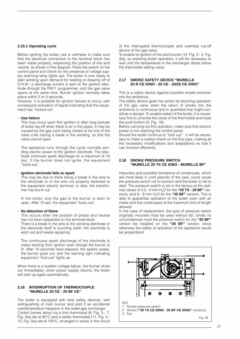
2.18 SMOKE PRESSURE SWITCH“MURELLE 20 TX CE IONO - MURELLE BF”
Impurities and possible formations of condensate, whichare more likely in cold periods of the year, could causethe pressure switch not to function and the boiler to fail tostart. The pressure switch is set in the factory at the opti-mal values of 4.5 - 6 mm H2O for the “20 TX - 20 BF” ver-sions, and 8 - 9 mm H2O for the “25 BF” version. This isable to guarantee operation of the boiler even with airintake and flue outlet pipes at the maximum limit of lengthallowed.In the case of replacement, the type of pressure switchoriginally mounted must be used without fail. Under nocircumstances must the pressure switch for the “20 BF”version be installed on the “25 BF” version, sinceotherwise the safety of operation of the appliance wouldbe jeopardized.
KEY1 Smoke pressure switch2 Venturi (“20 TX CE IONO - 25 BF CE IONO” versions)3 Fan
Fig. 26

22
2.19 DISASSEMBLY OF OUTER CASING
To disassemble the outer casing, proceed as follows(Fig. 27):– pull the front panel forwards so as to release it from
the slot-in pins located on the sides (3) and (4);– unscrew the screws (1) that fasten the sides to the
base and brackets of the smoke chamber;– push the sides (3) and (4) upwards, sliding them out
of their slots.
KEY1 Self-tapping screws2 Rear panel3 L.H. side panel4 R.H. side panel5 Front panel
Fig. 27

23
3 Use and maintenance
3.1 PRELIMINARY CHECKS UPON COMMISSIONING
When carrying out commissioning of the boiler, you arerecommended to perform the following checks:– make sure that the system is charged with water and
is thoroughly vented;– make sure that any shutoff valves are open;– check that the pipe for expulsion of products of combu-
stion is unobstructed and has been properly installed;– make sure that the boiler is set for operation for the
type of gas supplied;– open the gas tap and check the soundness of the
connections including that of the burner;– purge the system, bleeding off the air present in the
gas pipe by operating the pressure relief valve on thegas valve inlet;
– make sure that the electrical connections have beenmade correctly and that the earth wire is connected toa good earthing system;
– check that there are no liquids or inflammable mate-rials in the immediate vicinity of the boiler.
3.1.1 Temperature adjustment of D.H.W.
The “MURELLE” boilers (except for “20 R - 20 BFR”models) are equipped with a potentiometer for adjustingthe temperature of D.H.W. with a setting range from 35°Cto 60°C. This system offers a double advantage:1) the boiler adapts perfectly to any type of D.H.W.
system, whether the mixing system is a mechanical ora thermostat-controlled type;
2) the thermal output is dosed according to the temperatu-re required, which means a considerable saving in fuel.
NOTE: In order to avoid any misunderstanding plea-se the remember that the value obtained by the pro-duct of temperature difference (in °C) between D.H.W.output and input into the boiler by the hourly flow ratemeasured on the tap, where hot water is drawn off(l/h), cannot be higher than the useful output develo-ped by the boiler. For measurements and checks onflow rate and temperature of D.H.W., use suitableinstruments, taking into consideration any heatdispersion along the stretch of piping between theboiler and the measuring point.
3.1.2 Adjustment of D.H.W. flow rate
The “MURELLE” boilers (except for “20 R - 20 BFR”models) have a three-way hydraulic valve of the pressureswitch type (Fig. 28), which, when at rest, keeps thesystem delivery flow open, whereas it switches instanta-neously to the recirculation position, shutting off heating,upon demand for D.H.W. To adjust the hot water flow rate,use the flow-rate regulator (2) on the pressure switch valve.Remember that the flow rates and corresponding tempe-ratures of use of hot water, given in Table 2, have beenobtained by positioning the selector of the circulationpump on the maximum value.
NOTE: Should there be any reduction in the D.H.W.flow rate, the filter (4) installed on the inlet to the pres-sure switch valve will need cleaning.
To gain access to the filter, first close the shutoff cockfor cold water intake located on the fixing jig and thenloosen the brass swivel connection (5).
3.2 DISASSEMBLY OF EXPANSION VESSEL
To disassemble the expansion vessel, proceed as follows(Fig. 29):– make sure that the water has been emptied out of the
boiler;– unscrew the connection (1) connecting the expansion
vessel to the boiler;– unscrew the screw retaining the bracket (5) to the
frame assembly, remove the bracket and the expan-sion vessel (2).
NOTE: Before refilling the system, using a pressuregauge attached to the valve (3) make sure that the expan-sion vessel is preloaded at a pressure of 0.8 to 1 bar.
KEY1 Pressure switch valve2 Flow-rate regulator3 Microswitch
4 Filter5 Swivel connection 1/2”6 Gasket ø 11,5/18,57 Water pressure switch
Fig. 28
KEY1 Connection 3/4”2 Expansion vessel3 Expansion vessel
preloaded valve
4 Screw M5x165 Fixing bracket
Fig. 29

24
3.3 GAS VALVE
The “MURELLE 20/25 CE - 20 BF CE” boilers are equip-ped standard with a HONEYWELL V4600N gas valvecomplete with a modulator screwed onto the pressureregulator (Fig. 30).
The “MURELLE IONO” versions, without pilot burner, areequipped standard with the SIT 837 TANDEM gas valve(Fig. 30/a).
The “MURELLE BF IONO” versions, without pilot burner,are equipped standard with the HONEYWELL VK4105Mgas valve (Fig. 30/b).
3.4 GAS VALVE ADJUSTMENT
Since all “MURELLE” versions are flame-modulation boi-lers, they have the gas valve set at two pressure values:maximum and minimum. According to the type of gas burnt, these correspond tothe values given in Table 8. Calibration of the gas pressu-res at the maximum and minimum values is done by SIMEin the factory. Consequently they should not be altered. Only when you switch from one type of gas supply(Natural gas) to another (L.P.G.) it is permitted to alter theoperating pressure.It is essential that this operation be carried out exclu-sively by authorized technical staff; otherwise, thewarranty will be rendered null and void.When the gas pressures are to be reset, this must bedone following a set order: first the maximum pressureand then the minimum for the models equipped with theV4600N and 837 TANDEM gas valve and vice versa forthe models equipped with the VK4105 gas valve.
3.4.1 Maximum pressure adjustment V4600N
To set the maximum pressure, proceed as follows (Fig. 31):– connect the pressure column or a pressure gauge to
the pressure inlet downstream of the gas valve;– remove the retaining spring, completely withdraw the
modulator (4) and loosen the locking nut (2); – tighten the screw (3) and set the knob of the D.H.W.
potentiometer to the maximum value (3, Fig. 32).– ignite the boiler by operating the switch and open the
hot water tap;– using a ø 12 spanner, turn the union (1) to arrive at the
maximum pressure value given in Table 8: to reducethe pressure, turn the union counterclockwise; toincrease the pressure, turn it clockwise;
– once setted the pressure value tighten the locking nut(2) and replace the modulator (4) in position;
– operate the main switch a number of times, keepingthe hot water tap open all the time, and check that thepressure corresponds to the values given in Table 8.
KEY1 Modulator2 EV1-EV2 coil3 Pressure inlet upstream4 Pressure inlet downstream
KEY 1 Ignite/extinguish button2 Modulator3 Electric operator4 Pilot burner adjusting screw5 Pressure inlet downstream6 Pressure inlet upstream
Fig. 30
Fig. 30/a
KEY1 Modulator2 EV1-EV2 coil3 Pressure inlet downstream4 Pressure inlet upstream
Fig. 30/b

25
3.4.2 Minimum pressure adjustment V4600N
To set the minimum pressure, proceed as follows (Fig. 31):– withdraw the modulator (4);– set the knob of the D.H.W. potentiometer to the maxi-
mum value (3, Fig. 32);– ignite the boiler by operating the switch and open the
D.H.W. tap;– turn the screw (3, Fig. 31) to arrive at the minimum
pressure value given in Table 8: to reduce the pressu-re, turn the screw counterclockwise; to increase thepressure, turn it clockwise;
– replace the modulator (4) in position;– operate the main switch a number of times, keeping
the D.H.W. tap open all the time, and check that thepressure corresponds to the values given in Table 8;
– Fix the modulator with its retaining spring.
3.4.3 Maximum pressure adjustment 837 TANDEM
To set the maximum pressure, proceed as follows (Fig.31/a):– connect the pressure column or a pressure gauge to
the pressure inlet downstream of the gas valve;– remove the plastic cap (1);– set the knob of the D.H.W. potentiometer to the maxi-
mum value (3, Fig. 32);– ignite the boiler by operating the switch and open the
hot water tap;– using a ø 10 spanner, turn the nut (3) to arrive at the
maximum pressure value given in Table 8: to reducethe pressure, turn the nut counterclockwise; to increa-se the pressure, turn it clockwise;
– operate the main switch a number of times, keepingthe hot water tap open all the time, and check that thepressure corresponds to the values given in Table 8.
3.4.4 Minimum pressure adjustment 837 TANDEM
To set the minimum pressure, proceed as follows (Fig.31/a):
– disconnect the electric power to the modulator;– set the knob of the D.H.W. potentiometer to the maxi-
mum value and open the hot water tap;– ignite the boiler by operating the switch and turn the
screw (2) keeping locked the nut (3) to arrive at theminimum pressure value given in Table 8: to reducethe pressure, turn the screw counterclockwise; toincrease the pressure, turn it clockwise;
– operate the main switch a number of times, keepingthe D.H.W. tap open all the time, and check that thepressure corresponds to the values given in Table 8;
– restore electric power to the modulator and replacethe plastic cap (1) in position.
3.4.5 Minimum pressure adjustment VK4105M
To set the minimum pressure, proceed as follows (Fig. 31/b):– connect the pressure column or a pressure gauge to
the pressure inlet downstream of the gas valve;– disconnect the electric power and remove the plastic
cap on the modulator (1);– set the knob of the D.H.W. potentiometer to the maxi-
mum value (3, Fig. 32);– ignite the boiler by operating the switch and open the
D.H.W. tap at a high flow rate;– using a ø 9 spanner, turn the nut (2) to arrive at the
minimum pressure value given in Table 8: to reducethe pressure, turn the nut counterclockwise; to increa-se the pressure, turn it clockwise;
– operate the main switch a number of times, keepingthe D.H.W. tap open all the time, and check that thepressure corresponds to the values given in Table 8;
– restore electric power to the modulator.
KEY1 Maximum pressure
adjusting union2 Lockin nut M133 Minimum pressure
adjusting screw4 Modulator 24 V
Burner Modulator Burner ModulatorType of gas max. pressure current min. pressure current
mbar mA mbar mA
Methane - G20 10 - 11 130 2 0
L.P.G. - G30 28 150 7 0
L.P.G. - G31 35 150 7 0
TABLE 8
Fig. 31
Fig. 31/b
KEY1 Plastic cap2 Minimum pressure
adjusting nut3 Maximum pressure
adjusting nut4 Modulator 24 V
LEGENDA1 Plastic cap2 Minimum pressure
adjusting screw3 Maximum pressure
adjusting nut
Fig. 31/a

26
3.4.6 Maximum pressure adjustment VK4105M
To set the maximum pressure, proceed as follows (Fig.31/b):– set the knob of the D.H.W. potentiometer to the maxi-
mum value (3, Fig. 32);– ignite the boiler by operating the switch and open the
D.H.W. tap at a high flow rate;– using a ø 7 spanner turn the nut (3, Fig. 31/b) to arrive
at the maximum pressure value given in Table 8: toreduce the pressure, turn the screw counterclockwise;to increase the pressure, turn it clockwise;
– operate the main switch a number of times, keepingthe D.H.W. tap open all the time, and check that thepressure corresponds to the values given in Table 8;
3.5 ADJUSTMENT OF HEAT OUTPUT FOR HEATING
To adjust boiler heat output for heating purposes, i.e.,modifying the setting made at the factory, which isapproximately 16 kW in the “20” vers. , 18 kW in the “25CE - 25 CE IONO” vers. and 19 kW in the “25 BF CEIONO” vers. use a screwdriver to adjust the heating heatoutput trimmer (2, Fig. 32).To increase working pressure, turn the trimmer clockwise(towards the + sign); to reduce pressure, turn the trimmercounterclockwise (towards the – sign).When the temperature read by the sensor corresponds tothe value selected on the potentiometer, the boiler willalready be at minimum burner flame. At this point, thepotentiometer will cause the burner to go out. To facilita-te the operations of adjusting heat output, see the pres-sure/heat output diagrams for natural gas (methane) andbutane or propane gas, shown in figs. 33 and 34.
3.6 PILOT BURNER ADJUSTMENT
The “MURELLE 20 CE - 20 BF CE” versions are equip-ped with pilot flame which, provided it is properly adju-sted, should envelop the end portion of the thermocoupleover a length of 8 to 10 mm. Adjustment is made by tur-ning the adjusting screw (4, Fig. 30):– to reduce gas flow, turn the screw clockwise;– to increase gas flow, turn the screw counterclockwise.
3.7 CONVERSION TO DIFFERENT GAS
To convert to butane gas (G30) or propane gas (G31),first replace the main nozzles and the pilot nozzle(“MURELLE 20 CE - 20 BF CE” versions).Proceed as follows (Fig. 35):– close the gas cock;– in the “MURELLE 20 CE - 20 BF CE” versions, unscrew
the interrupted thermocouple (6) and the pilot feed pipeconnection (3), and remove the ignition electrode (5);
25
20
15
10
8,1 (7.000) 11,6 (10.000) 17,4 (15.000) 23,2 (20.000)
POTENZA TERMICA kW (kcal/h)
30
529,1 (25.000)
3.5.2 Pressure/heat output diagram for L.P.G. gas (G30)
HEAT OUTPUT kW (kcal/h)
NOZZ
LE P
RESS
URE
mba
r
Fig. 34
11
10
9
8
7
6
5
4
3
2
1
8,1 (7.000) 11,6 (10.000) 17,4 (15.000) 23,2 (20.000)
POTENZA TERMICA kW (kcal/h)
29,1 (25.000)
3.5.1 Pressure/heat output diagram for natural gas
HEAT OUTPUT kW (kcal/h)
NOZZ
LE P
RESS
URE
mba
r
Fig. 33
KEY1 Heating
potentiometer2 Trimmer3 D.H.W.
potentiometer
Fig. 32
25
20
15
10
8,1 (7.000) 11,6 (10.000) 17,4 (15.000) 23,2 (20.000)
POTENZA TERMICA kW (kcal/h)
30
35
529,1 (25.000)
3.5.3 Pressure/heat output diagram for L.P.G. gas (G31)
HEAT OUTPUT kW (kcal/h)
NOZZ
LE P
RESS
URE
mba
r
Fig. 34/a

27
– remove the pilot burner (8), and replace the pilotnozzle (4);
– slide out the burner unit (11);– replace the main nozzles (12) located on the burner
manifold (9), inserting the copper washer (10). Use aø 7 spanner to perform this operation;
– reassemble all the parts, proceeding in reverse order.– In the versions equipped with the V4600N gas
valve replace the cylindrical spring (Fig. ) of themodulator with the red painted one supplied withthe conversion kit.
– remove the “L.P.G.-MET” connector link on the card(10, Fig. 25) and set it on “L.P.G.”;
– to set the values of maximum and minimum gas pres-sure, follow the instructions given in Section 3.4,according to the type of gas valve used.Except for making the setting, it is not necessary toperform any other operations on the valve modulator;
– the gas feed pressure must under no circumstancesexceed 50 mbar;
– after have ultimated the conversion of the boiler, pleasestick onto the casing panel the plate showing the relevantfeeding gas which is included into the conversion kit.
NOTE: After assembling all the gas connections, atest for gas tightness must be carried out usingsoapy water or special products. DO NOT USENAKED FLAMES.
3.8 FILTER ON GAS PIPE
The gas valve used on the “MURELLE” boilers is fittedstandard with an inlet filter, which, however, is not ableto entrap all the impurities in the gas or in gas mainspipes.To prevent malfunctioning of the valve, or in certaincases even to cut out the safety device with which thevalve is equipped, install an adequate filter on the gaspipe.
3.9 CLEANING AND MAINTENANCE
At the end of each heating season, it is essential to havethe boiler thoroughly checked and cleaned out.Proceed as follows:– turn the main switch off to stop electric power rea-
ching the boiler and close the gas feed cock;– disassemble the outer casing as described in section
2.19;– remove the smoke chamber, unscrewing the fixing
screws;– disassemble the gas burner manifold unit, as descri-
bed in Section 3.7;– to clean the burner, blow in a jet of air, so as to remove
any dust particles that may have accumulated;– clean the heat exchanger, removing any dust or resi-
due from combustion;– when cleaning the heat exchanger or the burners,
chemical products or steel brushes MUST NOT BEUSED;
– make sure that the tops of the burners with the holesare free from encrustations;
– during burner disassembly and assembly, be verycareful not to exert force on the delicate items, suchas the tip of the thermocouple or the ignition and sen-sing electrodes;
– reassemble the items removed from the boiler, makingsure to follow the correct sequence;
– check the chimney to make sure that the flue is clean;– check operation of the equipment and/or the pilot bur-
ner and main burner;– do not use abrasive products for cleaning the control
panel;– after assembly of all the gas connections, these must
be tested for soundness, using soapy water or appro-priate products. DO NOT USE NAKED FLAMES.
Preventive maintenance and checking of efficientoperation of equipment and safety devices must becarried out exclusively by authorized technical per-sonnel.
KEY1 Swivel connection 1/2”2 Locknut 1/2”3 Pilot pipe ø 64 Pilot nozzle5 Ignition plug6 Interrupted thermoc.
7 Hex screw TE M5 x 108 Pilot burner9 Burner manifold
10 Washer ø 6,111 Burners12 Nozzle13 Screw TCB M4 x 6
Fig. 35
Fig. 36
LEGENDA1 Locking nut M132 Cylindrical spring3 Maximum adj. pressure union4 Minimum adj. pressure screw5 Modulator 24 V6 Retaining spring7 Plastic cap with screw

28
FAULTS
Pilot fails to light, no discharge sparknoted on electrode.
Pilot burner goes out when ignitionbutton is released.
Main burner does not start either todraw off D.H.W. or for heating.
Boiler turns on, but after 10 seconds“locks out” (“IONO” version).
Gas valve fails to modulate in D.H.W. phase.
Gas valve works only at minimumheat output in heating phase.
Main burner fails to start in D.H.W. generation phase.
LIKELY CAUSES AND SOLUTIONS
– Check that gas inflow is regular and that all air hasbeen purged from pipes.
– Check the 1.6 Amp fuse is sound.– Check the micro PVG contact is not faulty; if neces-
sary, replace it (“BF” version).– Check the ignition wire is not faulty and that the con-
tact is good on the connection terminals.– The electrode may be ill-positioned or require replace-
ment because it is broken.– Electrical ignition A does not work; replace (“BF” ver-
sion).– Piezo-ignition does not work; replace.
– Check the pilot flame hits the thermocouple adequa-tely.
– Adjust gas flow to pilot.– Safety thermostat may be faulty; replace.– Replace interrupted thermocouple.– Replace gas valve.
– Check water pressure switch PA; if necessary, repla-ce it.
– The smoke thermostat has tripped; reset it.– Check whether electric power is reaching the gas
valve actuator; check its operation and, if necessary,replace it.
– Check operation of limit thermostat TL and smokepressure switch PF (“BF” version).
– The fan V is operating but at low rpm, so failing to acti-vate the fume pressure switch PF (“BF” version);replace fan.
– If, notwithstanding the checks listed above, the mainburner stills fails to start, replace the electronic card.
– Check that during electric wiring the position of lineand neutral have not been inverted.
– Check whether the equipment has a burnt fuse.– Sensing electrode is faulty; replace.– Equipment is faulty; replace.
– SS sensor is interrupted; replace.– Modulator M has a break in winding; replace– Electronic card is faulty; replace.
– SM sensor is interrupted; replace.
– Check that the pressure switch valve piston movesproperly activating microswitch at end of stroke. If thisdoes not happen, check that the water pressure corre-sponds to the minimum specified; if necessary, repla-ce pressure switch valve.
– The microswitch of the pressure switch valve is faulty;replace it.
3.10 FAULT FINDING

29
D.H.W. arrives very hot but at low flow rate.
D.H.W. taps run neither hot water nor cold.
D.H.W. potentiometer or heatingpotentiometer fails to regulate properly.
Boiler is noisy or heat exchangermakes a sizzling sound.
Boiler safety valve keeps tripping.
Radiators fail to heat up in winter.
Main burner burns badly: flames toohigh, too yellow.
Smell of unburnt gases.
Boiler operates but does not increasetemperature.
In the “MURELLE BF CE” vers., withswitch ON, fan fails to turn at min speed.
– Unscrew completely the screw (2, Fig. 28) of the pres-sure switch valve.
– Check that the filter (4, Fig. 28) on the pressure switchvalve inlet is clean.
– Mains water charge pressure is too low; install water-lift system to provide adequate static head.
– Exchanger or D.H.W. outlet pipe obstructed by limedeposits; remove encrustations.
– Check that the sensor in question is in contact with thepipe; use silicone paste to improve sensitivity.
– The sensor in question is faulty; replace.
– Check whether circulation pump P is obstructed; ifnecessary clear it out.
– Unclog impeller of circulation pump, clearing awayany impurities or sediments.
– Circulation pump is burnt out or has a lower rpm thanrequired; replace.
– Check boiler output is adequate for actual needs ofheating system.
– Check charge cock is closed. If it doesn’t close pro-perly, replace.
– Check system cold charge pressure is not too high;keep to recommended values.
– Check whether safety valve is out of calibration; ifnecessary, replace.
– Check whether the vessel is sufficiently capacious tocontain the water for the system.
– Check preloading pressure of expansion vessel.– Replace expansion vessel if faulty.
– “Summer/Winter” switch is on “Summer”; switch to“Winter”.
– Room temp. thermostat TA is set too low or needsreplacing because faulty.
– Electrical connections of room temp. thermostat TAare wrong.
– Microswitch of pressure switch valve is faulty; replace.
– Check that pressure of burner gas is regular.– Check burners are clean.– Check coaxial assembly has been installed correctly
(“BF” version)
– Check boiler is properly clean.– Check draught is sufficient.– Check gas consumption is not too high.
– Check gas consumption is not lower than it should be.– Check boiler is clean.– Check boiler is sized in proportion to system.
– Check electrical connections and whether electricpower is arriving.

30
In the “MURELLE BF CE” version, upondemand for D.H.W. or heating, fan fails to turn at max speed.
In the “MURELLE 20 TX CE IONO” vers., the fan turns but the burner does not start.
In the “MURELLE 20 TX CE IONO” vers., fan fails to turn.
– Check capacitor C; if faulty, replace.– Replace fan.
– Make sure the smoke pressure switch PF is workingand that the corresponding contact is in rest condi-tion.
– Check whether connection tubes of smoke pressureswitch PF are obstructed and, if necessary, cleanaway impurities or condensate.
– Smoke pressure switch PF needs replacing with a newfactory-calibrated one.
– Replace electronic board.
– Check whether connection pipe of smoke pressureswitch PF are obstructed and, if necessary, cleanaway impurities or condensate.
– Smoke pressure switch PF needs replacing with a newfactory-calibrated one.
– Check whether electric power is reaching the termi-nals of the activator motor.
– Motor winding is burnt out; replace.

Fonderie Sime S.p.A. - via Garbo, 27 - 37045 Legnago (Vr)Tel. 0442/631111 - Fax Serv. Commerciale 0442/631293 - Fax Serv. Tecnico 0442/631292
Cod
.6151113


