22
MURENA Doppler detector with digital processing for external protection Installation Manual †Edition 1.6

MURENA
Doppler detector with digital processing for external protection
Installation ManualEdition 1.6
CIAS Elettronica S.r.l. Ed. 1.6
Manuale d’installazione Pag. 2 di 36 Murena/Murena-Plus24
INDEX
1 DESCRIPTION ....................................................................................................................................................... 20
1.1 Product Description ............................................................................................................................................ 20 1.2 Block Schematic ................................................................................................................................................. 21
2 INSTALLATION ..................................................................................................................................................... 22
2.1 Preliminary Information ..................................................................................................................................... 22 2.2 Accessories ......................................................................................................................................................... 22 2.3 Site Preparation .................................................................................................................................................. 23 2.4 Dimensions and shape of the detection field ...................................................................................................... 23
3 CONNECTIONS ..................................................................................................................................................... 25
3.1 Terminals, Connectors and Circuit Functions .................................................................................................... 25 3.2 Power Supply Connections ................................................................................................................................. 27 3.3 Connections to the Control panel ....................................................................................................................... 27
3.3.1 Alarm Contacts .............................................................................................................................................. 28 3.3.2 Stand-by Connections .................................................................................................................................... 28 3.3.3 Test Connections ........................................................................................................................................... 28
3.4 Serial Line RS-485 ............................................................................................................................................. 29 3.4.1 RS-485 Serial Line Connections.................................................................................................................... 29
4 SET-UP AND VERIFICATION ............................................................................................................................. 30
4.1 Calibration and verification on-board ................................................................................................................. 30 4.1.1 Working on the board .................................................................................................................................... 30
4.2 Calibration using Software ................................................................................................................................. 33
5 MAINTENANCE AND SERVICE ........................................................................................................................ 34
5.1 Fault Finding ...................................................................................................................................................... 34 5.2 Service Kit .......................................................................................................................................................... 34
6 CHARCTERISTICS ............................................................................................................................................... 35
6.1 Technical Characteristics.................................................................................................................................... 35 6.2 Functional Characteristics .................................................................................................................................. 36

CIAS Elettronica S.r.l. Ed. 1.6
Installation Manual Pag. 20 of 36 Murena/Murena-Plus24
1 DESCRIPTION
1.1 Product Description
Murena is a volumetric microwave sensor, using the Doppler effect and digital signal processing, for external protection. The size and shape of the detection field make it particularly suitable for the protection of areas completely free of obstacles or for irregular shaped areas with fixed obstacles present. Murena is available in the following versions:
- Murena - Murena Plus - Murena C (Curtain) - Murena Plus C - Murena Plus 24
Murena can be used either as a “fan” pattern in open areas where the environmental situation is difficult to protect with other types of detector or as “fingers” (Murena Curtain) particularly suitable for covering the front of buildings, ensuring the face of the building is protected against attack. Using this configuration (Murena Curtain) it is important that there are no indentations or protrusions that allow the intruder to pass quickly through the very narrow microwave beam. Murena Curtain can be mounted vertically above the access that requires protection. For correct operation, in addition to the installation method described above, the maximum distance should be set to a value less than or equal to the height of the device above the ground. The interface between the microwave transmitter-receiver is designed using a special circuit which generates a modulation signal on the transmitter, demodulating and pre-amplifying the received signal using two separate channels. This special circuit, linking the new concept MW transmitter-receiver, allows the creation of a much better signal/noise ratio, especially for very low frequencies, which relate to slow movements across the lobes of protection. In this way there is a drastic reduction in the differences in sensitivity between movements longitudinal and transverse to the lobes of protection, characteristic in most Doppler effect sensors. This performance is then enhanced by subsequent signal processing which, after amplification, is digitised using an analogue/digital convertor. This passes the digitised signals to the on-board microprocessor, which analyses them, in real time as the situation evolves. Using appropriate algorithms it is possible to measure the distance and the mass of the object moving in the detection field, analysing all the received data using “Fuzzy” logic. This avant-garde approach means that most of the problems created by external environments on mono-static microwave sensors (those with the transmitter and receiver in the same head) can be overcome. The on board microprocessor also analyses the operating condition of the microwave components, detecting fault conditions and attempts to mask the detector. There is a complex diagnostic of all the circuit, which can provide specific alarms for detector faults. Finally, it is also possible to make remote functional tests, such that the proper operation of the detector can be checked centrally. The design includes a minimum range function to eliminate signals created by small objects close to the detector and a maximum range function to de-limit the detector analysis area. Set, for example, to 8m, the signal created by a human body at 10m will not be considered for analysis in the generation of alarms.
CIAS Elettronica S.r.l. Ed. 1.6
Installation Manual Pag. 21 of 36 Murena/Murena-Plus24
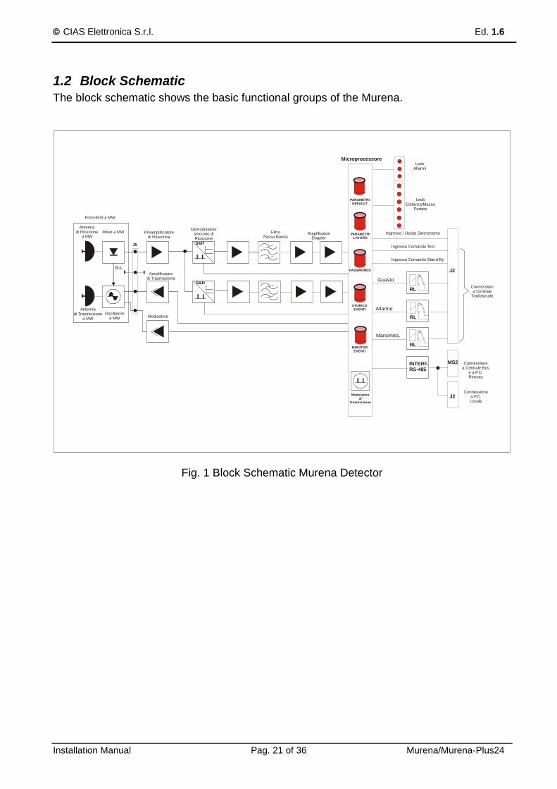
1.2 Block Schematic
The block schematic shows the basic functional groups of the Murena.
Antennadi Ricezione
a MWMixer a MW
Front-End a MW
Antennadi Trasmissione
a MW
Oscillatorea MW
Preamplificatoredi Ricezione
FiltroPassa Banda
LedsAllarmi
LedsDistanza/Massa
Portata
AmplificatoriDoppler
Amplificatoredi Trasmissione
Demodulatoresincrono diRicezione
Modulatoredi
Trasmissione
S&H
S&H
O.L.
J5
Microprocessore
Ingresso Comando Test
Ingresso Comando Stand-By
RL
RL
RL
Manomiss.
Allarme
Guasto
MS2
J2
INTERF.RS-485
Connessionea P.C.Locale
Connessionea Centrale Bus
e a P.C.Remoto
Connessionia Centrale
Tradizionale
J2
PARAMETRIDEFAULT
PARAMETRILAVORO
STORICOEVENTI
MONITOREVENTI
PASSWORDS
Ingresso / Uscita Sincronismo
Modulatore
Fig. 1 Block Schematic Murena Detector

CIAS Elettronica S.r.l. Ed. 1.6
Installation Manual Pag. 22 of 36 Murena/Murena-Plus24
2 INSTALLATION
2.1 Preliminary Information
The Murena detector is designed to operate in an external environment, and is therefore supplied in a waterproof housing, which contains all of the electronic components and interconnections. This housing is provided with clamp that allows the use of a suitable wall bracket or the optional pole bracket for mounting on a 60mm outside diameter post. Cable access is via a watertight gland and if necessary there is a second access on the base for the mounting of a second gland.
Figure 1
2.2 Accessories
The following accessories are available for the Murena sensor:
Wall Bracket 10 cm.
Wall Bracket 30 cm.
Wall Bracket 40 cm
Post Bracket 10 cm.
Murena-RS comprising anti-rain shield and back cover
Interface converter RS-485/USB “Kit USB”
Management Software “Wave Test2” The anti-rain shield and extra back cover are accessories required in all situations when the Murena is not sheltered from the rain, to avoid water droplets gathering on the face of the unit and sliding down, which can affect the processing. In all other cases the rain is recognised and discriminated using a special filter (FRF Fuzzy Rain Filter) which allows secure operation and prevents false alarms, even in the heaviest rain.

CIAS Elettronica S.r.l. Ed. 1.6
Installation Manual Pag. 23 of 36 Murena/Murena-Plus24
2.3 Site Preparation
The Murena detector is a detector that, thanks to it operating mode (Doppler effect), does nor require any specific preparation of the area to be protected. On the contrary, it lends to being used in those situations where other types of detector will face serious, if not insurmountable, difficulties. Therefore, Murena can be used to effectively cover dead zones in barrier systems, where there is insufficient space to implement cross-overs or overlaps. Another important application is in the protection of building fascias, balconies and terraces. Ensure that the wall or ceiling bracket is well fixed, that the Murena is not exposed to the rain (or use the optional rain shield and back cover accessories), that it is not looking directly at fluorescent lights and that it is not positioned in front of fans or vents (especially metal) with movable vanes that can generate unwanted signals. Murena can work in conjunction with all CIAS bi-static detectors (Minermo, Ermusa, Ermo barriers) without any particular precautions, without affecting the operation of the Murena or the barrier, whether the Murena is positioned close to either the receiver or transmitter.
2.4 Dimensions and shape of the detection field
The size of the detection field is asymmetric with a horizontal detection lobe of approximately 90° and a vertical lobe of approximately 40°. The lobes are shown in figure 2.
7
6
5
4
3
2
1
0
1
2
3
4
5
6
7
1 2 3 4 5 6 7 8 9 10 11 120
7
6
5
4
3
2
1
0
1
2
3
4
5
6
7
1 2 3 4 5 6 7 8 9 10 11 120
HORIZONTALPlane Detection Lobe
VERTICALPlane Detection Lobe
Figure 2 Using default parameters, suggested height of installation for Murena and Murena Plus, in fan mode, is from 1 to 2 mt.

CIAS Elettronica S.r.l. Ed. 1.6
Installation Manual Pag. 24 of 36 Murena/Murena-Plus24
The size of detection for Murena Plus Curtain has an amplitude of 90° on vertical plane and 15° on horizontal plane. Dimensions of the lobes are shown in the below figure
7
6
5
4
3
2
1
0
1
2
3
4
5
6
7
1 2 3 4 5 6 7 8 9 10 11 120
7
6
5
4
3
2
1
0
1
2
3
4
5
6
7
1 2 3 4 5 6 7 8 9 10 11 120
VERTICALPlane Detection Lobe
HORIZONTALPlane Detection Lobe
Using default parameters, suggested height of installation for Murena Curtain is from 2,5 to 4 mt. The size of detection for Murena Plus 24 has an amplitude of 45° on horizontal plane and 18° on vertical plane. Dimensions of the lobes are shown in the below figure
14
12
10
8
6
4
2
0
2
4
6
8
10
12
14
2 4 6 8 10 12 14 16 18 20 22 240
14
12
10
8
6
4
2
0
2
4
6
8
10
12
14
2 4 6 8 10 12 14 16 18 20 22 240
HORIZONTALPlane Detection lobe
VERTICALPlane Detection lobe
Using default parameters, suggested height of installation for Murena Plus 24, in fan mode, is from 1 to 2 mt .
CIAS Elettronica S.r.l. Ed. 1.6
Installation Manual Pag. 25 of 36 Murena/Murena-Plus24
3 CONNECTIONS
3.1 Terminals, Connectors and Circuit Functions
1 2 3 4 1 2 3 4 5 6 7 8 9 10
MS2 MS1
+13,8 GND LH LO AL AL TMP TMP FLT FLT STBY TST GND SYNC
DEV10 DEV1 FUN
S1
SW4
SW3 SW2 SW1
DL
7
DL
8
DL
9DL1
DL2
DL3
DL4
DL5
DL6
ON
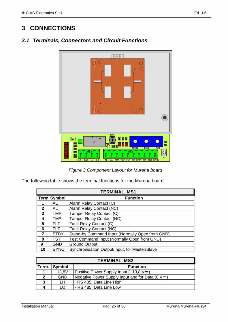
Figure 3 Component Layout for Murena board
The following table shows the terminal functions for the Murena board
TERMINAL MS1
Term Symbol Function
1 AL Alarm Relay Contact (C)
2 AL Alarm Relay Contact (NC)
3 TMP Tamper Relay Contact (C)
4 TMP Tamper Relay Contact (NC)
5 FLT Fault Relay Contact (C)
6 FLT Fault Relay Contact (NC)
7 STBY Stand-by Command Input (Normally Open from GND)
8 TST Test Command Input (Normally Open from GND)
9 GND Ground Output
10 SYNC Synchronisation Output/Input, for Master/Slave
TERMINAL MS2
Term. Symbol Function
1 13,8V Positive Power Supply Input (+13,8 V )
2 GND Negative Power Supply Input and for Data (0 V )
3 LH +RS 485 Data Line High
4 LO - RS 485 Data Line Low
CIAS Elettronica S.r.l. Ed. 1.6
Installation Manual Pag. 26 of 36 Murena/Murena-Plus24
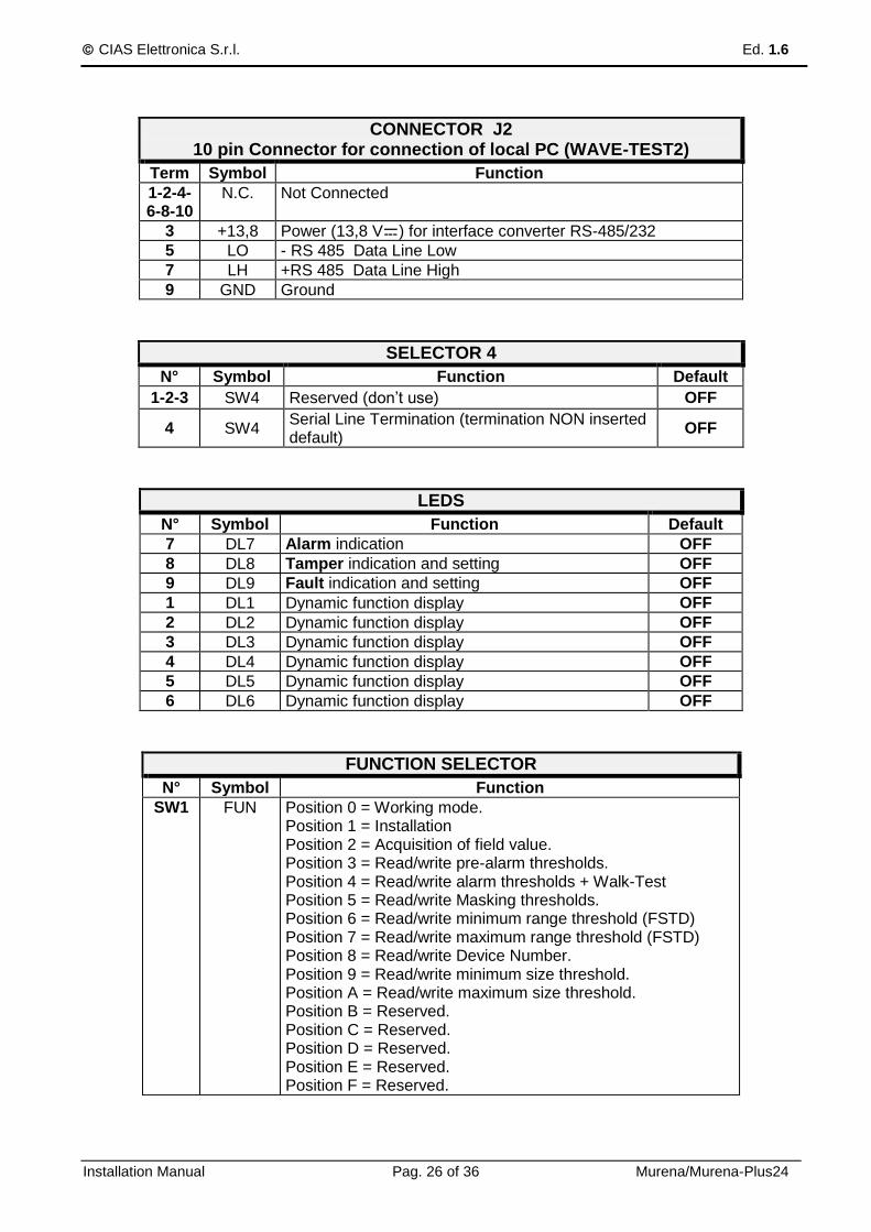
CONNECTOR J2 10 pin Connector for connection of local PC (WAVE-TEST2)
Term Symbol Function
1-2-4-6-8-10
N.C. Not Connected
3 +13,8 Power (13,8 V ) for interface converter RS-485/232
5 LO - RS 485 Data Line Low
7 LH +RS 485 Data Line High
9 GND Ground
SELECTOR 4
N° Symbol Function Default
1-2-3 SW4 Reserved (don’t use) OFF
4 SW4 Serial Line Termination (termination NON inserted default)
OFF
LEDS
N° Symbol Function Default
7 DL7 Alarm indication OFF
8 DL8 Tamper indication and setting OFF
9 DL9 Fault indication and setting OFF
1 DL1 Dynamic function display OFF
2 DL2 Dynamic function display OFF
3 DL3 Dynamic function display OFF
4 DL4 Dynamic function display OFF
5 DL5 Dynamic function display OFF
6 DL6 Dynamic function display OFF
FUNCTION SELECTOR
N° Symbol Function
SW1 FUN Position 0 = Working mode. Position 1 = Installation Position 2 = Acquisition of field value. Position 3 = Read/write pre-alarm thresholds. Position 4 = Read/write alarm thresholds + Walk-Test Position 5 = Read/write Masking thresholds. Position 6 = Read/write minimum range threshold (FSTD) Position 7 = Read/write maximum range threshold (FSTD) Position 8 = Read/write Device Number. Position 9 = Read/write minimum size threshold. Position A = Read/write maximum size threshold. Position B = Reserved. Position C = Reserved. Position D = Reserved. Position E = Reserved. Position F = Reserved.

CIAS Elettronica S.r.l. Ed. 1.6
Installation Manual Pag. 27 of 36 Murena/Murena-Plus24
PARAMETER READ/WRITE and DEVICE NUMBER SELECTORS
N° Symbol Function
SW3 DEV10 10 Way Switch for reading or setting parameters (Tens)
SW2 DEV1 10 Way Switch for reading or setting parameters (Units)
ALIGNMENT/SET UP CONFIRMATION BUTTON
N° Symbol Function
1 S3 Activate/confirm writing/acquisition phase of alignment/setup
3.2 Power Supply Connections
The Murena must have a direct current supply at a nominal voltage of 13.8 V . The connection between the Murena and the power supply must be of adequate dimensions, with the cross-section of the conductors calculated based on the length of the connection and the current requirements of the apparatus. For very long connections a supplementary power supply is recommended. Connect the 13.8V and GND wires respectively to terminals 1 and 2 of Terminal block MS2. The cable carrying the power supply to the apparatus should be screened, with the screen connected to ground at the power supply end only.
3.3 Connections to the Control panel
Connections to the control unit should be made using a screened cable. The Murena has three normally activated relays, each of which provides a normally closed, voltage free contact. These relays will be de-activated and their contacts will open for the following events:
- Alarm - Tamper - Fault
There are also three inputs for activating the following functions:
- Test - Stand-by

CIAS Elettronica S.r.l. Ed. 1.6
Installation Manual Pag. 28 of 36 Murena/Murena-Plus24
3.3.1 Alarm Contacts
The output contacts are static relays with a capacity of 100mA max. NB: The Alarm, Tamper and Fault contacts have a series resistance of 40 ohm when closed (secure). ALARM RELAY The alarm relay de-activates and the contact opens each time movement is detected in the detection field and the mass passes the program level “man”, or masking of the detector. TAMPER RELAY The tamper relay de-activates and the contact opens when the housing is opened. FAULT RELAY The tamper relay de-activates and the contact opens when the power supply voltage is outside the limits of +11.5Vdc and +14.8Vdc or the internal temperature is outside the limits of 30°C and +65°C. The Murena can easily be connected to any conventional alarm control panel by using either an on/off star connection or a balanced line
3.3.2 Stand-by Connections
To activate the Stand-by function it is necessary to connect terminal 7 “STBY” of MS1 to GND. N.B. Stand-by does not inhibit the normal operation of the detector. It stops the
recording of events in the History and Monitor files.
3.3.3 Test Connections
To activate the Test function it is necessary to connect terminal 8 “TST” of MS1 to GND for at least 10 sec. The Murena conducts a series of automatic functional self checks. If the test is successful the alarm relay contact will open.

CIAS Elettronica S.r.l. Ed. 1.6
Installation Manual Pag. 29 of 36 Murena/Murena-Plus24
3.4 Serial Line RS-485
The Murena detector has a standard RS-485 serial interface. The communication parameters are as follows: Mode: Asynchronous Speed: 9600 b/s Character length: 8 bit Parity Check: None Stop Bit: 1 The serial connection between the various installed detectors must use a low capacitance (< 70 pF/m) braided screen cable, for example “Belden9842” The serial connection can be used either for communicating events (Alarm, Tamper, Fault) and receiving commands (Test, Stand-by) from a control unit or cabling system that supports the C-ONE Bus protocol (IB-System), or for connection by the Wavetest 2 software. This software allows the remote management of all the operating parameters, display in real time of all the fundamental parameters relating to an intrusion (signal, distance, target size, ..) and the acquisition of the History and Monitor events stored in the detector.
3.4.1 RS-485 Serial Line Connections
The connection can be of the “Multi-drop” type, making it possible to connect many detectors in parallel on the same serial line (configuration Bus). The connections are made to Terminal Block MS2, with the conductor relating to RS-485 data negative (RS-485 -) to terminal 4 “L0”, the conductor relating to RS-485 data positive (RS-485 +) to terminal 3 “LH”, and the conductor relating to the ground reference to terminal 2 “GND”. To connect this serial line to a PC it is necessary to use an RS 485/232 convertor if the PC has an RS232 port available or an RS485/USB convertor if it has a USB port.
Cable for connecting the detector To a maintenance P.C. with WAVE TEST 2 SW
Interface Terminals
MS2
25 pin Connector
(D Type) of the convertor
RS485/USB Convertor Terminals
N° N° N° Symbol Function
1 12 +13,8 Power (13,8 V ) for 485/232 convertor
2 9 1 GND Data/power ground 485/232 convertor
3 10 2 LH 485 Data Line High for RS 485
4 11 3 LO 485 Data Line Low for RS 485

CIAS Elettronica S.r.l. Ed. 1.6
Installation Manual Pag. 30 of 36 Murena/Murena-Plus24
4 SET-UP AND VERIFICATION
4.1 Calibration and verification on-board
The Murena has an in-built system for setting and reading the operating parameters which simplifies the installation and periodic maintenance, without the need for any specific test equipment.
4.1.1 Working on the board
To remove the radome (front cover) release the four screws without removing them. Removing the radome from the back plate will open the “Tamper” micro-switch. Connect the power supply (13.8 Vdc) to terminals 1 and 2 of MS2 (fig.3) To set the operating parameters without using any test equipment proceed as follows:
a) Rotate function switch SW1 to Position 1. This activates the installation phase of the Murena. Led DL1DL6 will display the signal level and, in the absence of movement, the ambient noise of the area.
b) Rotate function switch SW1 to Position 2,
Rotate switches SW3 (tens) and SW2 (units) till 0 value ensuring during this operation that there are no obstacles in front of the detector, to ensure accurate acquisition. Press button S1 to start the acquisition of the field values and DL8 and DL9 will come on to confirm acquisition.
c) Rotate function switch SW1 to Position 3, and it is possible to read and/or modify the Pre-alarm threshold. When the target dimensions pass the pre-alarm threshold the Murena Plus will activate the fuzzy analysis of the signal. Led DL1DL6 will display the level of the target dimensions, 3 led on indicating 50% of the maximum dimensions achievable (the dimensions of an average size man is equivalent to about 50) To Read the pre-alarm threshold value:
Rotate function switch SW2 (units) until the red led (DL9) comes on. Note the position of SW2.
Rotate function switch SW3 (tens) until the red led (DL8) comes on. Note the position of SW3. The values read on these switches varies between 01 and 99, default of 20 for Murena, Murena Plus, Murena 24. 15-30 for Murena Plus Curtain. 10-15 for Murena Plus Curtain installed as Rain.
To Modify the pre-alarm threshold value:
Rotate switches SW3 (tens) and SW2 (units) to the value required.
Press S1 to confirm the setting and to acquire the new threshold value. To increase the sensitivity set a lower value minimum recommended 5. During normal operation the value of the pre-alarm threshold must not be higher the value of the minimum target dimension threshold.
NB: The value of pre-alarm threshold must be less or equal to the value of the minimum size of the target

CIAS Elettronica S.r.l. Ed. 1.6
Installation Manual Pag. 31 of 36 Murena/Murena-Plus24
d) Rotate function switch SW1 to Position 4, and it is possible to read and/or modify
the Alarm threshold. The alarm threshold is used to determine whether, at the end of the analysis process, there is a large enough signal to generate an alarm. To Read the alarm threshold value:
Rotate function switch SW2 (units) until the red led (DL9) comes on. Note the position of SW2.
Rotate function switch SW3 (tens) until the red led (DL8) comes on. Note the position of SW3. The values read on these switches vary between 01 and 99 (default of 50).
To Modify the alarm threshold value:
Rotate switches SW3 (tens) and SW2 (units) to the value required.
Press S1 to confirm the setting and to acquire the new threshold value. To increase the sensitivity set a lower value. To decrease the sensitivity set a higher value.
During this phase (SW1 in Position 4) it is possible to make a Walk-Test. Any disturbance in the protection field that exceeds the characteristics set up and validated by the analysis process will activate the buzzer with an intermittent sound, while led DL1DL6 will indicate the level reached by the alarm analysis process. When this reaches the level that will generate the alarm the buzzer will activate continuously and all six led will come on.
e) Rotate function switch SW1 to Position 5, and it is possible to read and/or modify
the Upper and Lower Masking threshold. The masking thresholds are set above and below the field value, memorised during the acquisition phase. To Read the masking threshold values:
Rotate function switch SW2 (units) until the red led (DL9) comes on. Note the position of SW2.
Rotate function switch SW3 (tens) until the red led (DL8) comes on. Note the position of SW3. The values read on these switches vary between 01 and 99 (default of 20).
To Modify the masking threshold values:
Rotate switches SW3 (tens) and SW2 (units) to the value required.
Press S1 to confirm the setting and to acquire the new threshold value.
f) Rotate function switch SW1 to Position 6, and it is possible to read and/or modify the Minimum Range (SR-FTD Short Range Fuzzy Target Discrimination). The minimum range creates an insensitive zone close to the detector, even if all the conditions are met to generate an alarm. The value is expressed in metres. Led DL1DL6 show the distance at which target movement will be detected. To Read the minimum range values:
Rotate function switch SW2 (units) until the red led (DL9) comes on. Note the position of SW2.
Rotate function switch SW3 (tens) until the red led (DL8) comes on. Note the position of SW3. The values read on these switches vary between 00 and 12 (default of 1m).
To Modify the minimum range values:
Rotate switches SW3 (tens) and SW2 (units) to the value required.
Press S1 to confirm the setting and to acquire the new range value. If a minimum range value greater than the maximum range value is entered by mistake the default values will automatically be entered.
CIAS Elettronica S.r.l. Ed. 1.6
Installation Manual Pag. 32 of 36 Murena/Murena-Plus24
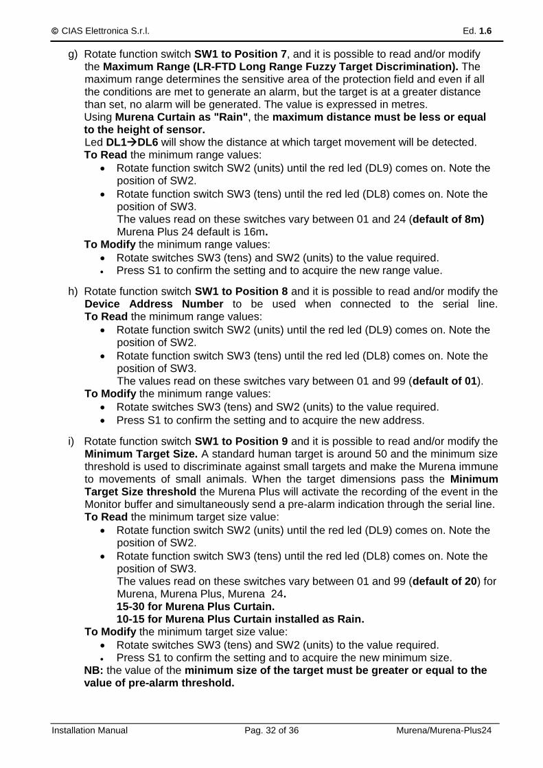
g) Rotate function switch SW1 to Position 7, and it is possible to read and/or modify the Maximum Range (LR-FTD Long Range Fuzzy Target Discrimination). The maximum range determines the sensitive area of the protection field and even if all the conditions are met to generate an alarm, but the target is at a greater distance than set, no alarm will be generated. The value is expressed in metres. Using Murena Curtain as "Rain", the maximum distance must be less or equal to the height of sensor. Led DL1DL6 will show the distance at which target movement will be detected. To Read the minimum range values:
Rotate function switch SW2 (units) until the red led (DL9) comes on. Note the position of SW2.
Rotate function switch SW3 (tens) until the red led (DL8) comes on. Note the position of SW3. The values read on these switches vary between 01 and 24 (default of 8m) Murena Plus 24 default is 16m.
To Modify the minimum range values:
Rotate switches SW3 (tens) and SW2 (units) to the value required. Press S1 to confirm the setting and to acquire the new range value.
h) Rotate function switch SW1 to Position 8 and it is possible to read and/or modify the Device Address Number to be used when connected to the serial line. To Read the minimum range values:
Rotate function switch SW2 (units) until the red led (DL9) comes on. Note the position of SW2.
Rotate function switch SW3 (tens) until the red led (DL8) comes on. Note the position of SW3. The values read on these switches vary between 01 and 99 (default of 01).
To Modify the minimum range values:
Rotate switches SW3 (tens) and SW2 (units) to the value required.
Press S1 to confirm the setting and to acquire the new address.
i) Rotate function switch SW1 to Position 9 and it is possible to read and/or modify the Minimum Target Size. A standard human target is around 50 and the minimum size threshold is used to discriminate against small targets and make the Murena immune to movements of small animals. When the target dimensions pass the Minimum Target Size threshold the Murena Plus will activate the recording of the event in the Monitor buffer and simultaneously send a pre-alarm indication through the serial line. To Read the minimum target size value:
Rotate function switch SW2 (units) until the red led (DL9) comes on. Note the position of SW2.
Rotate function switch SW3 (tens) until the red led (DL8) comes on. Note the position of SW3. The values read on these switches vary between 01 and 99 (default of 20) for Murena, Murena Plus, Murena 24. 15-30 for Murena Plus Curtain. 10-15 for Murena Plus Curtain installed as Rain.
To Modify the minimum target size value:
Rotate switches SW3 (tens) and SW2 (units) to the value required. Press S1 to confirm the setting and to acquire the new minimum size.
NB: the value of the minimum size of the target must be greater or equal to the value of pre-alarm threshold.

CIAS Elettronica S.r.l. Ed. 1.6
Installation Manual Pag. 33 of 36 Murena/Murena-Plus24
j) Rotate function switch SW1 to Position A and it is possible to read and/or modify the Maximum Target Size. To Read the maximum target size value:
Rotate function switch SW2 (units) until the red led (DL9) comes on. Note the position of SW2.
Rotate function switch SW3 (tens) until the red led (DL8) comes on. Note the position of SW3. The values read on these switches vary between 01 and 99 (default of 70). We suggest a value of 90 for Murena Plus Curtain.
To Modify the maximum target size value:
Rotate switches SW3 (tens) and SW2 (units) to the value required. Press S1 to confirm the setting and to acquire the new maximum size.
k) Rotate function switch SW1 to Position 0 and press button S1. This concludes the installation phase. Leave the switch in this position for normal operation.
4.2 Calibration using Software
For display and extremely accurate management of all the parameters of the detector, complete with analogue threshold levels and received signals, use the Wave-Test 2 software running on a PC. Refer to the software manual for connection details and detailed procedures for the management of the detector.
Analogue Values screenshot for Murena, Murena Plus and Murena Plus Curtain
CIAS Elettronica S.r.l. Ed. 1.6
Installation Manual Pag. 34 of 36 Murena/Murena-Plus24
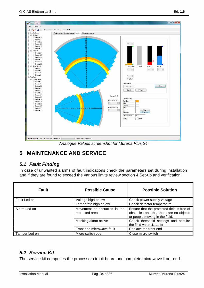
Analogue Values screenshot for Murena Plus 24
5 MAINTENANCE AND SERVICE
5.1 Fault Finding
In case of unwanted alarms of fault indications check the parameters set during installation and if they are found to exceed the various limits review section 4 Set-up and verification.
Fault
Possible Cause
Possible Solution
Fault Led on Voltage high or low Check power supply voltage
Temperate high or low Check detector temperature
Alarm Led on Movement or obstacles in the protected area
Ensure that the protected field is free of obstacles and that there are no objects or people moving in the field.
Masking alarm active Check threshold settings and acquire the field value 4.1.1 b)
Front end microwave fault Replace the front end
Tamper Led on Micro-switch open Close micro-switch
5.2 Service Kit
The service kit comprises the processor circuit board and complete microwave front-end.
CIAS Elettronica S.r.l. Ed. 1.6
Installation Manual Pag. 35 of 36 Murena/Murena-Plus24
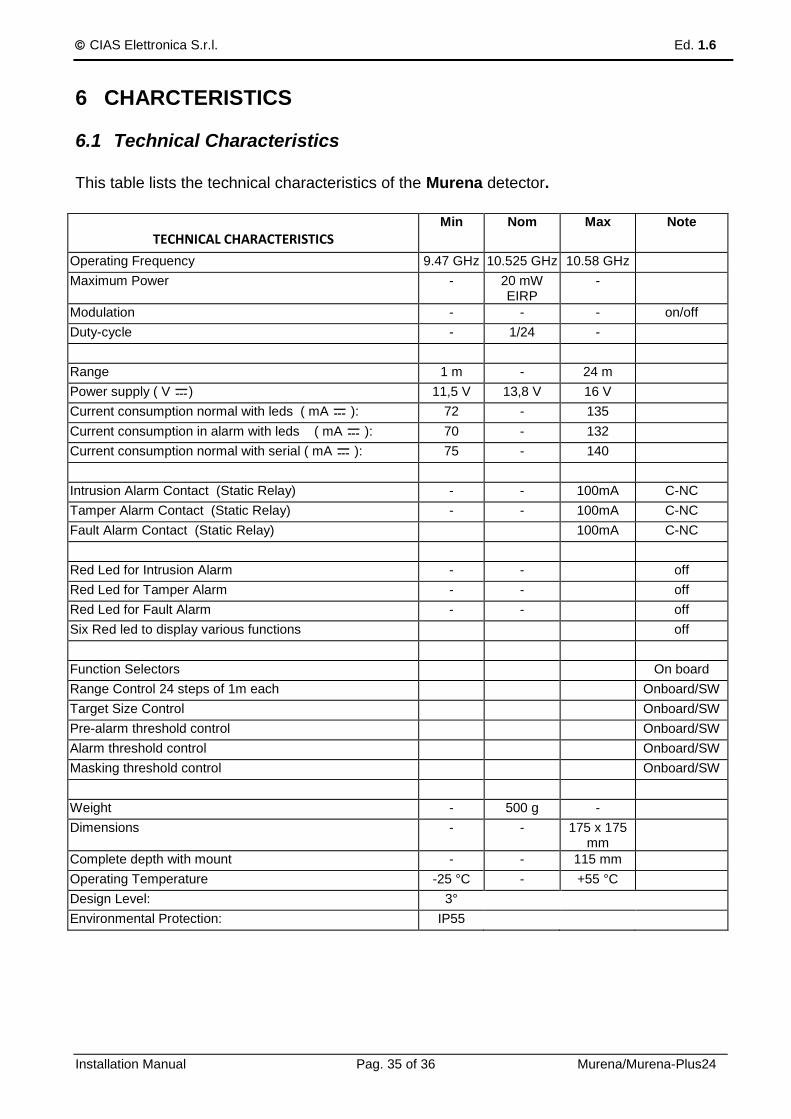
6 CHARCTERISTICS
6.1 Technical Characteristics
This table lists the technical characteristics of the Murena detector.
TECHNICAL CHARACTERISTICS Min Nom Max Note
Operating Frequency 9.47 GHz 10.525 GHz 10.58 GHz
Maximum Power - 20 mW EIRP
-
Modulation - - - on/off
Duty-cycle - 1/24 -
Range 1 m - 24 m
Power supply ( V ) 11,5 V 13,8 V 16 V
Current consumption normal with leds ( mA ): 72 - 135
Current consumption in alarm with leds ( mA ): 70 - 132
Current consumption normal with serial ( mA ): 75 - 140
Intrusion Alarm Contact (Static Relay) - - 100mA C-NC
Tamper Alarm Contact (Static Relay) - - 100mA C-NC
Fault Alarm Contact (Static Relay) 100mA C-NC
Red Led for Intrusion Alarm - - off
Red Led for Tamper Alarm - - off
Red Led for Fault Alarm - - off
Six Red led to display various functions off
Function Selectors On board
Range Control 24 steps of 1m each Onboard/SW
Target Size Control Onboard/SW
Pre-alarm threshold control Onboard/SW
Alarm threshold control Onboard/SW
Masking threshold control Onboard/SW
Weight - 500 g -
Dimensions - - 175 x 175 mm
Complete depth with mount - - 115 mm
Operating Temperature -25 °C - +55 °C
Design Level: 3°
Environmental Protection: IP55

CIAS Elettronica S.r.l. Ed. 1.6
Installation Manual Pag. 36 of 36 Murena/Murena-Plus24
6.2 Functional Characteristics
1) Generation Of a true RADAR signal (Radio Detection And Ranging)
2) Analysis Of the RADAR signal using DSP
3) Analysis And filtering in the time domain FFT
4) Analysis Of the target distance using FUZZY control
5) Analysis Of the target speed using FUZZY control
6) Analysis Of the target size using FUZZY control
7) Analysis Of the direction of movement
8) Analysis Of the threat of the target according to FUZZY control
Analysis For discrimination between rain and a true target
Analysis For discrimination between noise and a true target
Analysis Of the maximum detection distance setting LRTD Long Range Target Discrimination
Analysis Of the minimum detection distance setting SRTD Short Range Target Discrimination
Analysis Of masking
9) Analysis Of the power supply voltage, High or Low.
10) Analysis Of the ambient temperature to detect events outside the normal operating range and to compensate for differences in signal due to temperature changes.
11) Analysis Of opening the cover (Radome).
12) Analysis * Of a Stand-by input to inhibit the recording of events in the History and Monitor internal memories of the Murena.
13) Analysis * Of a Test input which activates an internal test of the Murena and opens the alarm relay if the test is successful (it creates an alarm status on the serial line with the Murena Plus).
14) Activation Of three static relays for alarm, tamper and fault.
15) Activation * Of sequential polling of the pre-alarm, alarm and tamper status on an RS485 serial line for connection with the IB-System interface.
16) Activation Of three leds for the indication of alarm, tamper and fault.
Activation Of 6 multi-functional led to show the distance or dimensions of the target or entering alarm condition.
Activation Of the buzzer during walk tests on reaching an alarm condition.
Availability Of a set of switches to activate the functions and to define of the entity.
17) Availability Of a lithium battery to maintain the data in the total absence of power.
18) Availability Of a clock and calendar to provide a date and time stamp for the events stored within the Murena as either history or monitor events.
19) Availability * Of a historical event archive, able to store up to 256 events with indication of the date, time, type of event and the values (in case they are specific to the event). This data can be acquired using the Wave Test 2 software and stored in historical files that can be viewed and/or printed.
20) Availability * Of an archive of up to 256 recordings, each 6.5 seconds long, of the detected analogue signal of the distance, speed and size of the target when this last parameter is above the pre-alarm threshold setting.
21) Availability Of a set of default parameters, which can be used from time to time if the Murena is not set for any reason or if, during a self diagnosis, it detects an incorrect value.
22) Availability * Of a connector for the connection of a PC via an RS-485 serial line, which allows the use of the Wave Test 2 for configuration, test and management of the detector.
23) Availability * Of an RS-485 serial line connection, which allows the connection of all the detectors on a common line, acquiring all the alarms over the line, issuing Stand-by and Test commands and carrying out calibration and management.
The functions marked with “*” are only active on the Murena Plus and Murena Plus24 version.

NOTE:

NOTE:

Con la presente, CIAS Elettronica, dichiara che questo rivelatore di intrusione “MURENA” è conforme ai requisiti essenziali ed alle altre disposizioni rilevanti della Direttiva 1999/5/CE (Art.3.1a-3.1b-3.2) Hereby, CIAS Elettronica, declares that this movement detector “MURENA” is in compliance with the essential requirement and other relevant provisions of Directive 1999/5/EC (Art.3.1a-3.1b-3.2)
Informazioni direttive Europee WEEE Questo apparecchio è contrassegnato in conformità alla Direttiva Europea 2002/96/EC, Waste Electrical and Electronic Equipment (WEEE) Assicurandosi che questo prodotto sia smaltito in modo corretto, l’utente contribuisce a prevenire le potenziali conseguenze negative per l’ambiente e la salute.
Il simbolo sul prodotto o sulla documentazione d’accompagnamento indica che questo prodotto non deve essere trattato come rifiuto domestico ma deve essere consegnato presso l’idoneo punto di raccolta per il riciclaggio d’apparecchiature elettriche ed elettroniche.
Disfarsene seguendo le normative locali per lo smaltimento rifiuti. Lo smaltimento abusivo è punito con le sanzioni previste dalla legislazione nazionale vigente
Il prodotto può essere riconsegnato al distributore/installatore a fine vita in occasione di un nuovo acquisto.
This product is marked in compliance with the European Directive 2002/96/EC, Waste Electrical and Electronic Equipment (WEEE). The correct disposal of the product will prevent potential negative consequences for the environment and the human health.
The symbol on the product or into the annexed documentation indicates that this product does not have to be dealt like domestic refusal but must be delivered near the suitable point of collection for the recycling of electrical and electronic equipment.
The illicit disposal will be endorsed according to local l regulations.
At the end of operative life the product can be given back to the vendor/installation organization in occasion of a new purchase.
Copyright CIAS Elettronica S.r.l.
Stampato in Italia / Printed in Italy
CIAS Elettronica S.r.l. Direzione, Ufficio Amministrativo, Ufficio Commerciale, Laboratorio di Ricerca e Sviluppo Direction, Administrative Office, Sales Office, Laboratory of Research and Development 20158 Milano, via Durando n. 38 Tel. +39 02 376716.1 Fax +39 02 39311225 Web-site: www.cias.it E-mail: [email protected] Stabilimento / Factory 23887 Olgiate Molgora (LC), Via Don Sturzo n. 17


