80
OPERATING INSTRUCTIONS Bidirectional data converter from CAN Scanner Network to serial host interface MUX400 Multiplexer
| Date post: | 12-Jun-2018 |
| Category: |
Documents |
| Upload: | hoangthuan |
| View: | 227 times |
| Download: | 0 times |
O P E R AT I N G I N S T R U C T I O N S
Bidirectional data converter from CAN Scanner
Network to serial host interface
MUX400
Multiplexer
Operating Instructions
MUX 400 Multiplexer
Software versions
Copyright
Copyright 2004
SICK AG Waldkirch
Auto Ident
Reute Facility
Nimburger Strasse 11
79276 Reute
Germany
Trademarks
Windows 98TM, Windows NTTM, Windows 2000TM, Windows XPTM and Internet ExplorerTM
are registered trademarks or trademarks of the Microsoft Corporation in the USA and other
countries.
Latest manual version
For the latest version of this manual (PDF), see www.sick.com.
Software/Tool Function Version
MUX 400-0000 Firmware 1.00 0000
CLV Setup Configuration software (Windows-based) V 4.0 O077
CLV Setup Help Online help (HTML) V 4.0 O077
2 © SICK AG · Division Auto Ident · Germany · All rights reserved 8 010 685/0000/25-03-2004
Operating Instructions
MUX 400 Multiplexer
Contents
Table of Contents1 Notes on this document................................................................................................91.1 Purpose ............................................................................................................................................9
1.2 Target audience.............................................................................................................................9
1.2.1 Installation, electrical connection, maintenance and replacement .....................9
1.2.2 Startup, operation and configuration ..............................................................................9
1.3 Information content......................................................................................................................9
1.4 Symbols used..............................................................................................................................10
2 Safety information........................................................................................................ 112.1 Authorized users ........................................................................................................................11
2.1.1 Installation and maintenance .........................................................................................11
2.1.2 Electrical connection and replacement ......................................................................11
2.1.3 Startup, operation and configuration ...........................................................................11
2.2 Intended use................................................................................................................................11
2.3 General safety instructions and protection measures ................................................12
2.4 Quick stop and quick restart..................................................................................................12
2.4.1 Switching off the MUX 400 .............................................................................................12
2.4.2 Restarting the MUX 400...................................................................................................12
2.5 Environmental information......................................................................................................12
2.5.1 Power requirements...........................................................................................................12
2.5.2 Disposal after final decommissioning .........................................................................12
3 Product description ..................................................................................................... 133.1 Design ............................................................................................................................................13
3.1.1 Scope of delivery.................................................................................................................13
3.1.2 Prerequisites for installation and start-up..................................................................13
3.1.3 Product features and functions of the MUX 400 (overview) ............................14
3.1.4 View of the MUX 400 ........................................................................................................15
3.2 Method of operation.................................................................................................................16
3.2.1 Function in the network ...................................................................................................16
3.2.2 Output format of the host interface .............................................................................17
3.2.3 Diagnosis functions ............................................................................................................19
3.3 Indicators and operating elements .....................................................................................19
3.3.1 Operating elements............................................................................................................19
3.3.2 Function of the LED indicators......................................................................................20
4 Installation...................................................................................................................... 214.1 Selecting the installation site.................................................................................................21
4.2 Installing the MUX 400 ............................................................................................................21
4.3 Removing the device................................................................................................................21
5 Electrical installation .................................................................................................. 225.1 Overview of the connection sequence ..............................................................................22
5.2 Electrical connections and cables .......................................................................................22
5.3 Connector pin and terminal strips assignment...............................................................23
5.3.1 “CAN“ connection ...............................................................................................................23
5.3.2 “AUX“ connection ................................................................................................................23
5.3.3 Terminal strips......................................................................................................................24
5.4 Planning the electrical installation........................................................................................24
5.4.1 Requirements for the CAN interface ..........................................................................24
5.4.2 Requirements for the host interface ..........................................................................25
5.4.3 Power supply.........................................................................................................................26
5.5 Making electrical connections...............................................................................................26
5.5.1 Connecting the power supply.........................................................................................26
5.5.2 Connecting the CAN interface to the network .........................................................26
5.5.3 Connecting the CAN interface (9-pin D Sub socket).............................................28
5.5.4 Connecting the host interface .......................................................................................28
5.5.5 Connecting the terminal interface ...............................................................................29
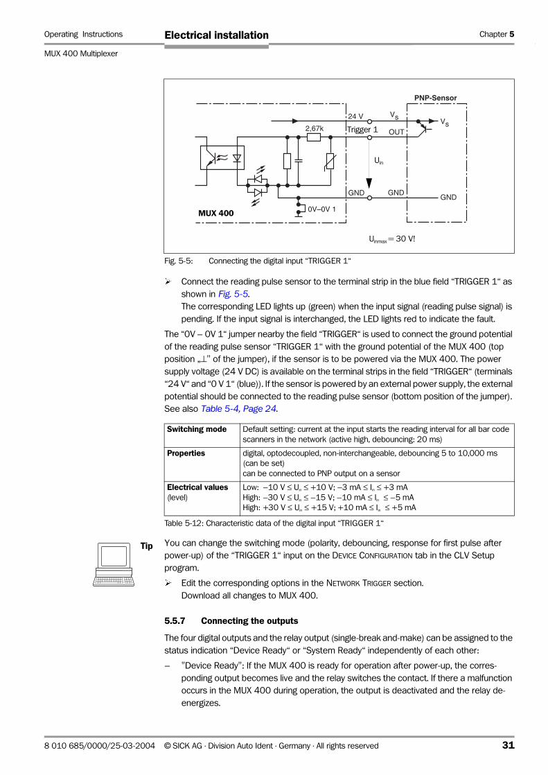
5.5.6 Connecting the digital input “TRIGGER 1“..................................................................30
5.5.7 Connecting the outputs ....................................................................................................31
8 010 685/0000/25-03-2004 © SICK AG · Division Auto Ident · Germany · All rights reserved 3
Operating Instructions
MUX 400 Multiplexer
Contents
6 Operation ........................................................................................................................ 346.1 Overview of the starting up sequence .............................................................................. 34
6.2 Default setting ............................................................................................................................ 34
6.3 Operating modes/functions................................................................................................... 35
6.4 Configuration (parameterizing) ............................................................................................. 35
6.4.1 Configuring the MUX 400 with the user interface of CLV Setup...................... 36
6.4.2 Function of the tabs in CLV Setup (overview) ........................................................ 38
6.4.3 Parameterization guide..................................................................................................... 39
6.4.4 Configuring the CAN interface of the MUX 400................................................ 406.4.5 Configuring the host interface of the MUX 400................................................ 416.4.6 Configuring the data strings of the host interface.................................................. 42
6.4.7 Configuring the network trigger (via MUX 400 ............................................... 436.4.8 Configuring the function of the MUX 400 outputs .............................................. 44
6.4.9 Configuring the function of the MUX 400 terminal interface ........................... 44
6.4.10 Downloading the parameter set and restarting the system.............................. 48
6.5 Further operation steps .......................................................................................................... 49
6.5.1 Displaying and editing operating data ........................................................................ 49
6.6 MUX 400 messages ................................................................................................................ 49
6.6.1 Displaying messages ....................................................................................................... 49
6.6.2 System messages.............................................................................................................. 49
6.6.3 Error rmessages ................................................................................................................. 50
6.7 Switching off the MUX 400.................................................................................................... 50
7 Maintencance................................................................................................................ 517.1 Cleaning the reading pulse sensor during operation................................................... 51
7.2 Maintenance ............................................................................................................................... 51
7.3 Disposal ....................................................................................................................................... 51
8 Troubleshooting ............................................................................................................ 528.1 Overview of the possible errors and malfunctions....................................................... 52
8.1.1 Electrical installation errors ............................................................................................. 52
8.1.2 Parameterization errors.................................................................................................... 52
8.1.3 Malfunctions during operation....................................................................................... 52
8.2 Monitoring error and malfunctions...................................................................................... 52
8.3 Error messages.......................................................................................................................... 52
8.4 Troubleshooting ......................................................................................................................... 52
8.4.1 General malfunction: MUX 400 not ready ................................................................ 53
8.4.2 Malfunction in Read mode: reading pulse error (Network trigger) .................. 53
8.4.3 Malfunction in Read mode: host interface data output error ............................ 54
8.5 Querying error codes with command strings.................................................................. 55
8.5.1 Command strings for server diagnosis (group queries) ...................................... 55
8.5.2 Command strings for network diagnosis (group queries)................................... 56
8.6 SICK Support............................................................................................................................... 57
9 Technical Data .............................................................................................................. 589.1 Data sheet MUX 400 Multiplexer ....................................................................................... 58
9.2 Dimensional drawings.............................................................................................................. 59
10 Appendix ......................................................................................................................... 6010.1 Overview ....................................................................................................................................... 60
10.2 Installation and operation of the PC-based “CLV Setup“ program ........................ 61
10.2.1 Preparing for installation .................................................................................................. 61
10.2.2 Performing installation ...................................................................................................... 61
10.2.3 Starting “CLV Setup“ ......................................................................................................... 64
10.2.4 CLV Setup graphical user interface ............................................................................. 66
10.2.5 Functions ............................................................................................................................... 67
10.2.6 Hot keys ................................................................................................................................. 67
10.2.7 Opening and closing tabs................................................................................................ 68
10.2.8 Online help – CLV Setup.................................................................................................. 68
10.2.9 Transferring parameter sets between CLV-Setup and MUX 400.................... 68
10.2.10 Dealing with unkown parameters................................................................................. 69
4 © SICK AG · Division Auto Ident · Germany · All rights reserved 8 010 685/0000/25-03-2004
Operating Instructions
MUX 400 Multiplexer
Contents
10.2.11 Writing a log file in terminal emulator ..........................................................................69
10.2.12 Starting CLV Setup with an INI file as argument .....................................................70
10.2.13 CLV Assistant ........................................................................................................................70
10.3 Configuring the MUX 400 with command strings ........................................................71
10.4 Replacing a MUX 400 (copying the parameter set).....................................................72
10.5 Accessories..................................................................................................................................74
10.5.1 Cables and plug-in connections ....................................................................................74
10.5.2 Reading pulse generators................................................................................................74
10.6 Supplementary documentation ............................................................................................74
10.7 Code table (Hex – ASCII) ........................................................................................................75
10.8 Copy of the EC Declaration of Conformity........................................................................76
10.9 Index ...............................................................................................................................................86
8 010 685/0000/25-03-2004 © SICK AG · Division Auto Ident · Germany · All rights reserved 5

Operating Instructions
MUX 400 Multiplexer
Tables and Figures
AbbreviationsCAN Controlled Area Network. (standardized field bus system with a messages-oriented data
transfer protocol)
CDB Connection Device Basic
CDM Connection Device Modular
CLV Code-Leser V-Prinzip (Code reader V principle)
CLX Code-Leser X-Prinzip (Code reader X principle, omnidirectional)
HTML Hyper Text Markup Language
I Input
ICR Image Code Reader
LED Light Emitting Diode
MUX Multiplexer
O Output
PLC Progammable Logic Controller
TablesTable 3-1: Meaning of the LED indicators....................................................................................20
Table 5-1: Admissible wire diameters on the terminal strips ...............................................22
Table 5-2: Pin assignment of the 9-pin D Sub socket “CAN“...............................................23
Table 5-3: Pin assignment of the 9-pin D Sub plug “AUX“ ....................................................23
Table 5-4: Jumpers on the MUX 400............................................................................................24
Table 5-5: CAN bus: Maximum cable length as a function of the data transfer rate..25
Table 5-6: CAN bus: Maximum stub lengths as a function of the data transfer rate .25
Table 5-7: CAN bus: Required wire diameter as a function of the data cable length.25
Table 5-8: Maximum cable lengths between MUX 400 and host......................................25
Table 5-9: Host interface: Assignment of the RS 232 signals on the RS 422
interface...............................................................................................................................28
Table 5-10: Communication parameters of the host interface (default setting).............29
Table 5-11: Communication parameters of the terminal interface ......................................30
Table 5-12: Characteristic data of the digital input “TRIGGER 1“..........................................31
Table 5-13: Characteristic data of the digital outputs “OUTPUT 1“ to “OUTPUT 4“ .......32
Table 5-14: Characteristic data of the output “RELAIS OUT“..................................................33
Table 6-1: Default settings of the MUX 400...............................................................................34
Table 6-2: Monitoring host interface“ function...........................................................................47
Table 8-1: Troubleshooting: restoring operation (network mode)......................................53
Table 8-2: Troubleshooting: network trigger error ....................................................................53
Table 8-3: Troubleshooting: errors in the data output to the host.....................................54
Table 8-4: Command strings for server diagnosis....................................................................55
Table 8-5: Network diagnosis: three types of status information about the
devices in the network...................................................................................................56
Table 8-6: Command strings for network diagnosis ................................................................56
Table 9-1: Technical specifications of MUX 400.......................................................................58
Table 10-1: Default settings of CLV Setup (extract)...................................................................64
Table 10-2: Accessories: cables and plug-in connections.......................................................74
Table 10-3: Supplementary documentation..................................................................................74
Table 10-4: Code table Hex – ASCII .................................................................................................75
6 © SICK AG · Division Auto Ident · Germany · All rights reserved 8 010 685/0000/25-03-2004

Operating Instructions
MUX 400 Multiplexer
Tables and Figures
FiguresFig. 3-1: Design of the MUX 400................................................................................................... 15
Fig. 3-2: Multiplexer function: Example of data flow via the
multiplexer to the host computer ................................................................................ 16
Fig. 3-3: Structure of block telegram............................................................................................ 18
Fig. 5-1: Connections and jumpers of the MUX 400............................................................. 24
Fig. 5-2: Principle: Wiring the CAN Scanner Network via CDB connection modules . 27
Fig. 5-3: Connecting the host interface....................................................................................... 28
Fig. 5-4: Connecting the terminal interface ............................................................................... 29
Fig. 5-5: Connecting the digital input “TRIGGER 1“................................................................. 31
Fig. 5-6: Connecting the digital output “OUTPUT 1“ ............................................................... 32
Fig. 5-7: Connection diagram of the output “RELAIS OUT“.................................................. 33
Fig. 6-1: CLV Setup: “CAN Interface“ tab ................................................................................... 40
Fig. 6-2: CLV Setup: “Host Interface“ tab................................................................................... 41
Fig. 6-3: CLV Setup: “Data string“ tab ......................................................................................... 42
Fig. 6-4: CLV Setup: “Device Configuration“ tab...................................................................... 43
Fig. 6-5: CLV Setup: “Auxiliary interface“ tab: Selecting the MUX Diagnosis................ 44
Fig. 6-6: CLV Setup: Display of the MUX Diagnosis in the
Terminal Emulator (Network OK) ................................................................................. 45
Fig. 6-7: CLV Setup: Display of the MUX Diagnosis in the
Terminal Emulator (network failure) ............................................................................ 45
Fig. 6-8: CLV Setup: “Auxiliary interface“ tab: Selecting the Server Diagnosis ............ 46
Fig. 6-9: CLV Setup: Display of the Server Diagnosis in the Terminal Emulator ......... 46
Fig. 6-10: CLV Setup: Display of the data transfer time (MUX Data Timimg) in
the Terminal Emulator ...................................................................................................... 47
Fig. 6-11: CLV Setup: Display of the data traffic on the host interface in
the Terminal Emulator ...................................................................................................... 48
Fig. 6-12: CLV Setup: “Operating data“ dialog box ................................................................... 49
Fig. 9-1: Dimensions of the MUX 400......................................................................................... 59
Fig. 10-1: CLV Setup: results of the AutoBaud detect function............................................ 65
Fig. 10-2: User interface of the “CLV Setup“ software ............................................................ 66
Fig. 10-3: CLV Setup: entering commands in the terminal emulator ................................. 71
Fig. 10-4: Copy of the Declaration of Conformity (Page 3, scaled down) ........................ 76
Fig. 10-5: Copy of the Declaration of Conformity (Page 2, scaled down) ........................ 77
8 010 685/0000/25-03-2004 © SICK AG · Division Auto Ident · Germany · All rights reserved 7

Operating Instructions
MUX 400 Multiplexer
Tables and Figures
Installation procedure (overview)CAN Scanner Network:
1. If you have not already done so, install the bar code scanners in the CAN Scanner
Network.
To simplify connection and set the default values for communication parameters,
mount and connect the CDB/CDM connection modules and CMC 400 cloning modules.
2. Organize the CAN Scanner Network logically (assign unique addresses from 1 to 63 and
configure the CMC 400).
3. Switch on the power supply to the bar code scanners.
MUX 400 Multiplexer:
4. Check scope of delivery for completeness.
5. Install the MUX 400 in the control cabinet onto the grounded top-hat rail.
6. Install the reading pulse sensor for reading pulse distribution in the network at an
appropriate position.
7. Connect the output of reading pulse sensor to the “TRIGGER 1“ input of the MUX 400.
8. Connect the host computer (PLC) to the host interface of MUX 400 (terminal strip).
9. Connect the CAN Scanner Network to the CAN interface of MUX 400 (terminal strip).
10. Connect the power supply 24 V DC +20 %/−10 % to the MUX 400.
11. Switch on the power supply to the MUX 400.
The MUX 400 starts. The “Device Ready” LED lights up after the self-test has been
completed successfully. The device is in network mode.
12. Switch on the PC and start WindowsTM (at least Windows 98TM required).
13. Install the accompanying “CLV-Setup“ configuration software and the online help “CLV
Setup Help“ from CD ROM (“Manuals & Software“) to PC.
14. Connect the PC to the terminal interface of MUX 400. Use a 3-core RS 232 data cable
(null modem cable) to connect the PC to the 9-pin connector “AUX“.
15. Start “CLV Setup“.
CLV Setup contacts the MUX 400 and copies the parameter set of the MUX 400 via an
upload. The parameter set is displayed on tabs.
16. Configure the MUX 400 for the application (CAN interface, host interface, input and
outputs diagnosis function)
17. To test the data converter carry out readings of the bar code scanners in the network.
Display the read results in the Terminal Emulator of CLV Setup.
18. Run a test under realistic conditions.
19. Check and optimize the set parameter values if necessary.
Copy the parameter set to the MUX 400 permanently via download.
20. Save the parameter set as a “*.scl“ configuration file in CLV Setup.
The MUX 400 is ready for operation with the application-specific settings.
8 © SICK AG · Division Auto Ident · Germany · All rights reserved 8 010 685/0000/25-03-2004

Operating Instructions Chapter 1
MUX 400 Multiplexer
Notes on this document
1 Notes on this document
1.1 Purpose
This document contains instructions for operating the MUX 400 Multiplexer in the variant:
• MUX 400-0000 (no. 1 026 219)
This document provides information on
• Installation and electrical connection
• Startup
• Operation and configuration (parameterizing)
• Maintenance
• Replacing the device while retaining the parameter set.
The multiplexer will all simply be called "MUX 400" below.
1.2 Target audience
This document is intended for persons who are responsible for the following activities:
1.2.1 Installation, electrical connection, maintenance and replacement
Electricians and service technicians
1.2.2 Startup, operation and configuration
Technicians and engineers
1.3 Information content
This document contains all of the information required to install, make electrical connections
and start up the MUX 400 with the factory default settings.
A series of step-by-step instructions is provided for each of these activities.
The MUX 400 is configured for specific applications using the Windows-based "CLV
Setup" software. Further assistance is also available in the form of the online help system
"CLV Setup Help". The procedure for installing and operating the user interface of the
software is described in Chapter 10.2 Installation and operation of the PC-based “CLV Setup“ program, Page 61.
Installation and configuration of the CAN Scanner Network using bar code scanners and
connection modules is proceeded according to the Operating Instructions “Application of the CAN interface“ (Nr. 8 009 180, English edition).
For further information on the design and the function of the multiplexer, please contact the
Auto Ident division at SICK AG.
Internet address: www.sick.de/mux400.
8 010 685/0000/25-03-2004 © SICK AG · Division Auto Ident · Germany · All rights reserved 9
Chapter 1 Operating Instructions
MUX 400 Multiplexer
Notes on this document
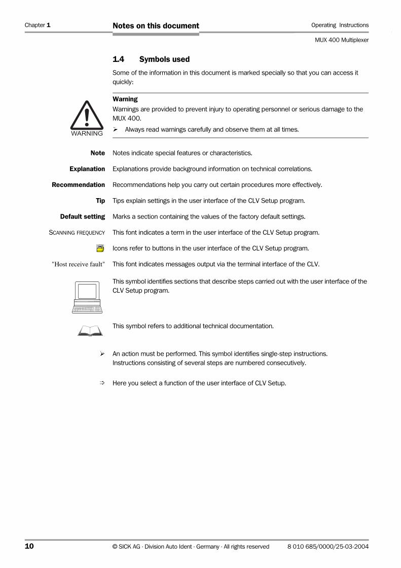
1.4 Symbols used
Some of the information in this document is marked specially so that you can access it
quickly:
Warning
Warnings are provided to prevent injury to operating personnel or serious damage to the
MUX 400.
¾ Always read warnings carefully and observe them at all times.
Note Notes indicate special features or characteristics.
Explanation Explanations provide background information on technical correlations.
Recommendation Recommendations help you carry out certain procedures more effectively.
Tip Tips explain settings in the user interface of the CLV Setup program.
Default setting Marks a section containing the values of the factory default settings.
SCANNING FREQUENCY This font indicates a term in the user interface of the CLV Setup program.
Icons refer to buttons in the user interface of the CLV Setup program.
"Host receive fault" This font indicates messages output via the terminal interface of the CLV.
This symbol identifies sections that describe steps carried out with the user interface of the
CLV Setup program.
This symbol refers to additional technical documentation.
¾ An action must be performed. This symbol identifies single-step instructions.
Instructions consisting of several steps are numbered consecutively.
Ö Here you select a function of the user interface of CLV Setup.
10 © SICK AG · Division Auto Ident · Germany · All rights reserved 8 010 685/0000/25-03-2004
Operating Instructions Chapter 2
MUX 400 Multiplexer
Safety information
2 Safety information
2.1 Authorized users
For the MUX 400 to function correctly and safely, it must be installed and configured by
sufficiently qualified personnel.
The following qualifications are required for the various tasks involved:
2.1.1 Installation and maintenance
• Practical basic technical training
• Knowledge of the standard guidelines relating to safety in the workplace
2.1.2 Electrical connection and replacement
• Practical training in electrical engineering
• Knowledge of the standard safety guidelines relating to electrical engineering
• Knowledge regarding the operation of the devices in the relevant application
(e.g. conveyor belt)
2.1.3 Startup, operation and configuration
• Knowledge regarding the operation of the devices in the relevant application
(e.g. conveyor belt)
• Knowledge of logical network organization
• Basic understanding of Windows 98TM, Windows NTTM, Windows 2000TM or
Windows XPTM
• Basic understanding of an HTML browser (e.g. Internet ExplorerTM)
• Basic understanding of data transfer methods
• Basic understanding of bar code technology
2.2 Intended use
The MUX 400 Multiplexer is designed to connect a maximum of 32 SICK bar code scanners
from the following series:
• CLV 42x to CLV 49x
• CLX 490
• ICR 85x
in the SICK CAN Scanner Network.
Specialized knowledge of networks and bus systems is not required. You can use the CDB/
CDM connection modules with the bar code scanners to set up your network (devices can
be connected more easily and communication parameters need only be configured once if
the CMC 400 cloning modules are used).
As a client, the MUX 400 organizes data conversion between the bar code scanners
(servers) in the network and a host computer (PLC). Data communication with the bar code
scanners takes place via CAN interfaces. Communication with the host is handled via an RS-
422 or RS-232 interface. The MUX 400 is suitable for installation in an industry-type control
cabinet on a grounded top-hat rail. If bar code scanners with optional heating are connected,
the MUX 400 must be installed outside the cooling area.
8 010 685/0000/25-03-2004 © SICK AG · Division Auto Ident · Germany · All rights reserved 11
Chapter 2 Operating Instructions
MUX 400 Multiplexer
Safety information
For information on installing and configuring the CAN Scanner Network with bar code
scanners and connection modules, see Operating Instructions “Application of the CAN interface“ (no. 8 009 180, English edition).
Any warranty claims vis-à-vis SICK AG will be rendered invalid if the device is used for any
other purpose or if changes are made to the device, including any made during the
installation and electrical connection procedures.
Note Don’t open the device. The producer warranty will be forfeited if the device is opened.
2.3 General safety instructions and protection measures
¾ Carefully read the general safety instructions and observe them at all activities at the
MUX 400. This also applies to the warnings provided for the activities described in each
chapter of this document.
2.4 Quick stop and quick restart
2.4.1 Switching off the MUX 400
¾ Switch off the power supply or remove the “24 V IN“ terminal strip from MUX 400
This can result in loss of the following (at the most):
• the application-specific parameter set, if it was only stored temporarily in the MUX 400
• Data that the MUX 400 has just received from the bar code scanners, or data it is
sending to the host.
2.4.2 Restarting the MUX 400
¾ Switch on the supply voltage or reattach the “24 V IN“ terminal strip to the MUX 400.
The MUX 400 resumes operation with the parameter set that was last stored permanently.
2.5 Environmental information
The MUX 400 is designed to cause minimum impact on the environment.
2.5.1 Power requirements
The MUX 400 has a max. power consumption of 5 W.
This value applies to devices with all digital outputs connected and where the bar code
scanners have a separate power supply.
2.5.2 Disposal after final decommissioning
Always dispose of unusable or irreparable devices in a manner that is not harmful to the
environment and in accordance with the applicable national waste disposal regulations. The
MUX 400 can be separated into recyclable secondary raw materials and special-category
waste (electronic scrap). See Chapter 7.3 Disposal, Page 51.
At present, SICK AG does not accept any unusable or irreparable devices.
12 © SICK AG · Division Auto Ident · Germany · All rights reserved 8 010 685/0000/25-03-2004
Operating Instructions Chapter 3
MUX 400 Multiplexer
Product description
3 Product description
3.1 Design
3.1.1 Scope of delivery
In the packaging the MUX 400 is supplied with the following:
• MUX 400-0000 with 2 snap-in brackets for top-hat rail mounting,
Additional: 2 mounting brackets,
Inserted: 10 terminal strips
• an information sheet (note on device)
Depending on the number of devices ordered, one or more copies of the following:
• CD ROM (no. 2 029 112) with
– "CLV-Setup" program for Windows TM and the "CLV-Setup Help" online help system
(HTML files)
– "CLV-Connect" PC software (HTML files showing terminal diagrams)
– MUX 400 Operating Instructions in English and German as PDF edition as well as
additional publications (connections module, other SICK bar code scanners)
– freely available "Acrobat Reader" PC software for reading PDF files
Note The latest versions of all current publications/programs on the CD ROM can also be
downloaded from www.sick .de.
Depending on the number of copies ordered, the delivery includes (optional):
• MUX 400 Operating Instructions in English and/or German (printed edition)
3.1.2 Prerequisites for installation and start-up
The following components are required to start up and configure the MUX 400 with the CAN
Scanner Network:
For the MUX 400:
• Grounded top hat rail in the system cabinet
• 24 V DC supply voltage +20 %/−10 % to IEC 364-4-41 (functional extra-low voltage),
power output > 5 W for MUX 400
Note Dimensioning of the power supply = power consumption of MUX 400 + power consumption
of the bar code scanners when power supplied via theMUX 400.
• If an external reading pulse is applied to the network via the “Trigger 1” sensor input on
the MUX 400: a suitable signal or a reading pulse sensor (e.g. a photoelectric reflex
switch) should be installed.
• Connection cables (not included in scope of delivery)
• A higher-level host computer (PLC) with a data interface of type RS 422 or RS 232
• PC with Windows 98TM, Windows NTTM, Windows 2000TM or Windows XPTM operating
system and “CLV-Setup“ configuration software from version 4.0 for parameterizing the
MUX 400 (on CD ROM)
• To use the online help system CLV Setup Help, an HTML browser is required, e.g..
Internet ExplorerTM (from Version 5.0)
• A 3-core RS 232 data cable for connecting the PC to the terminal interface of the
MUX 400.
8 010 685/0000/25-03-2004 © SICK AG · Division Auto Ident · Germany · All rights reserved 13

Chapter 3 Operating Instructions
MUX 400 Multiplexer
Product description
For connecting to the “AUX” connector, a 3-core RS 232 null modem cable (RxD and
TxD crossed) with 9-pin D Sub socket, e. g. no. 2 014 054
For the CAN Scanner Network:
• Bar code scanners from the CLV 42x to CLV 49x, CLX 490, and ICR 85x series
• Connection cables
• Operating instructions “Application of the CAN Interface” (No. 8 009 180, English
edition) for configuring the CAN Scanner Network (on CD ROM)
• Operating instructions for the bar code scanners and CDB/CDM connection modules
and for the CMC 400 cloning module, if used (on CD ROM)
• Connection diagrams in the CLV Connect PC program, version 2.0 upwards, for
connecting the network devices and the host (on CD ROM)
3.1.3 Product features and functions of the MUX 400 (overview)
High-performance multiplexer:
• Convenient connection of up to 32 bar code scanners using a CAN bus
• High data transfer rate to the host
• Continuous monitoring of bar code scanner presence on the network and possible
system malfunctions
Safety and user-friendly features:
• Specialized knowledge of networks and bus systems is not required
• Robust, compact metal housing, IP 20, CE certificate
• Installation as a module in the system cabinet
• Automatic self-test at system start-up
• Network maintenance requirements indicated by a signal at the switching output or by
means of a diagnosis telegram on the terminal interface
• Operating data display
• Future proof thanks to firmware update (flash PROM) via serial data interface
• 24 V DC power supply, low power consumption
Easy operation/configuration:
• With “CLV Setup” software for Windows (online) and help system
• Alternatively with simple command strings that can also be used for adjusting special
devices
• 11 LEDs for displaying status and malfunctions
• Optional display for showing network status
Operating modes:
• Network mode
• Parameterization
Reading pulse distribution in the network:
• External reading pulse via MUX 400 (sensor input or serial interface)
Data output (host interface):
• Single or block telegrams
14 © SICK AG · Division Auto Ident · Germany · All rights reserved 8 010 685/0000/25-03-2004
Operating Instructions Chapter 3
MUX 400 Multiplexer
Product description
Electrical interfaces:
• CAN interface, data transfer rate, device number and output format parameterizable
• Serial host interface (RS 422 or RS 232) with variable transfer rate, protocol and
telegram structure
• Serial terminal interface (RS 232) as auxiliary data interface with special diagnosis
functions
• Digital input for reading pulse
• 4 digital outputs + 1 relay output for signaling device and network status information
Connections:
• All interfaces are connected via pluggable screw terminal strips and D Sub connectors
3.1.4 View of the MUX 400
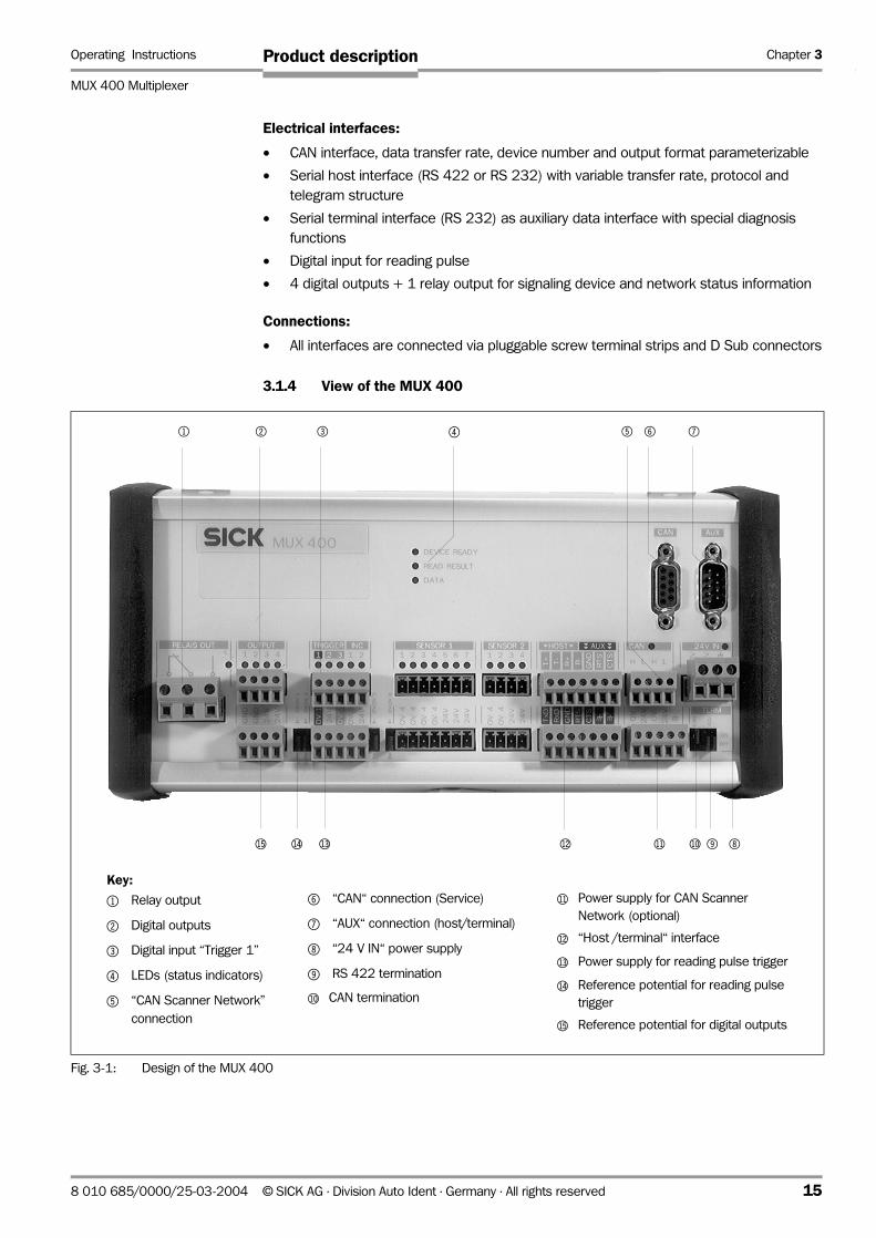
Fig. 3-1: Design of the MUX 400
1 2 3 4 5 6 7
89blbmbnbobpbq
Key:
1 Relay output
2 Digital outputs
3 Digital input “Trigger 1”
4 LEDs (status indicators)
5 “CAN Scanner Network”
connection
6 “CAN“ connection (Service)
7 “AUX“ connection (host/terminal)
8 “24 V IN“ power supply
9 RS 422 termination
bl CAN termination
bm Power supply for CAN Scanner
Network (optional)
bn “Host /terminal“ interface
bo Power supply for reading pulse trigger
bp Reference potential for reading pulse
trigger
bq Reference potential for digital outputs
8 010 685/0000/25-03-2004 © SICK AG · Division Auto Ident · Germany · All rights reserved 15
Chapter 3 Operating Instructions
MUX 400 Multiplexer
Product description
3.2 Method of operation
3.2.1 Function in the network
The MUX 400 can be used to connect up to 32 bar code scanners with one single data
interface to the host computer (PLC) in the CAN Scanner Network. As a client, the
multiplexer manages the bar code scanners (servers) with the device numbers 1 to 63 and
organizes rapid data conversion between the bar code scanners in the network and the host
computer.
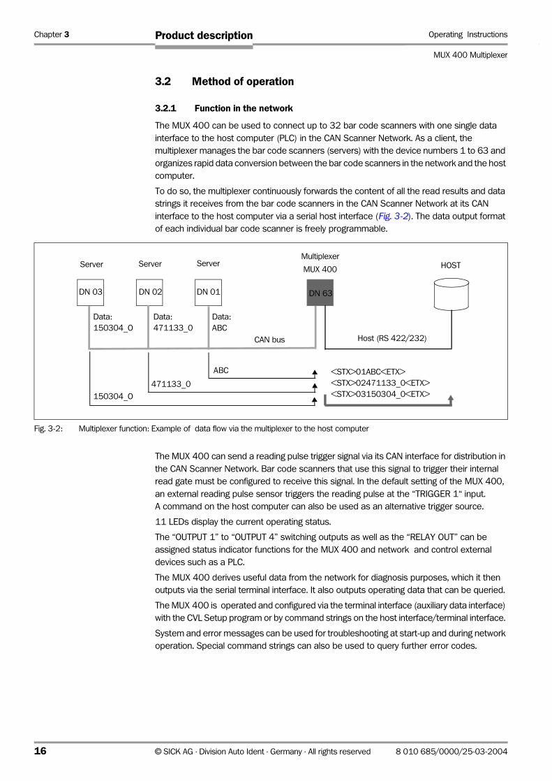
To do so, the multiplexer continuously forwards the content of all the read results and data
strings it receives from the bar code scanners in the CAN Scanner Network at its CAN
interface to the host computer via a serial host interface (Fig. 3-2). The data output format
of each individual bar code scanner is freely programmable.
The MUX 400 can send a reading pulse trigger signal via its CAN interface for distribution in
the CAN Scanner Network. Bar code scanners that use this signal to trigger their internal
read gate must be configured to receive this signal. In the default setting of the MUX 400,
an external reading pulse sensor triggers the reading pulse at the “TRIGGER 1“ input.
A command on the host computer can also be used as an alternative trigger source.
11 LEDs display the current operating status.
The “OUTPUT 1” to “OUTPUT 4” switching outputs as well as the “RELAY OUT” can be
assigned status indicator functions for the MUX 400 and network and control external
devices such as a PLC.
The MUX 400 derives useful data from the network for diagnosis purposes, which it then
outputs via the serial terminal interface. It also outputs operating data that can be queried.
The MUX 400 is operated and configured via the terminal interface (auxiliary data interface)
with the CVL Setup program or by command strings on the host interface/terminal interface.
System and error messages can be used for troubleshooting at start-up and during network
operation. Special command strings can also be used to query further error codes.
Fig. 3-2: Multiplexer function: Example of data flow via the multiplexer to the host computer
CAN bus Host (RS 422/232)
Data:
ABC
DN 01 DN 63
Server Server ServerMultiplexer
MUX 400HOST
ABC <STX>01ABC<ETX>
<STX>02471133_0<ETX>
<STX>03150304_0<ETX>
471133_0
DN 02DN 03
Data:
471133_0
Data:
150304_O
150304_O
16 © SICK AG · Division Auto Ident · Germany · All rights reserved 8 010 685/0000/25-03-2004
Operating Instructions Chapter 3
MUX 400 Multiplexer
Product description
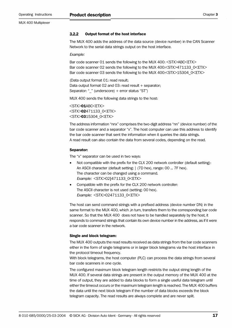
3.2.2 Output format of the host interface
The MUX 400 adds the address of the data source (device number) in the CAN Scanner
Network to the serial data strings output on the host interface.
Example:
Bar code scanner 01 sends the following to the MUX 400: <STX>ABC<ETX>
Bar code scanner 02 sends the following to the MUX 400:<STX>471133_0<ETX>
Bar code scanner 03 sends the following to the MUX 400:<STX>15304_0<ETX>
(Data output format 01: read result;
Data output format 02 and 03: read result + separator;
Separator: “_” (underscore) + error status “ST”)
MUX 400 sends the following data strings to the host:
<STX>01ABC<ETX>
<STX>02471133_0<ETX>
<STX>0315304_0<ETX>
The address information “nnx” comprises the two-digit address “nn” (device number) of the
bar code scanner and a separator “x”. The host computer can use this address to identify
the bar code scanner that sent the information when it queries the data strings.
A read result can also contain the data from several codes, depending on the read.
Separator:
The “x” separator can be used in two ways:
• Not compatible with the prefix for the CLX 200 network controller (default setting):
An ASCII character (default setting: (7D hex), range: 00 ... 7F hex).
The character can be changed using a command.
Example: <STX>02471133_0<ETX>
• Compatible with the prefix for the CLX 200 network controller:
The ASCII character is not used (setting: 00 hex).
Example: <STX>02471133_0<ETX>
The host can send command strings with a prefixed address (device number DN) in the
same format to the MUX 400, which ,in turn, transfers them to the corresponding bar code
scanner. So that the MUX 400 does not have to be handled separately by the host, it
responds to command strings that contain its own device number in the address, as if it were
a bar code scanner in the network.
Single and block telegram:
The MUX 400 outputs the read results received as data strings from the bar code scanners
either in the form of single telegrams or in larger block telegrams via the host interface in
the protocol timeout frequency.
With block telegrams, the host computer (PLC) can process the data strings from several
bar code scanners in one cycle.
The configured maximum block telegram length restricts the output string length of the
MUX 400. If several data strings are present in the output memory of the MUX 400 at the
time of output, they are added to data blocks to form a single useful data telegram until
either the timeout occurs or the maximum telegram length is reached. The MUX 400 buffers
the data until the next block telegram if the number of data blocks exceeds the block
telegram capacity. The read results are always complete and are never split.
8 010 685/0000/25-03-2004 © SICK AG · Division Auto Ident · Germany · All rights reserved 17

Chapter 3 Operating Instructions
MUX 400 Multiplexer
Product description
Note A single data string from a bar code scanner is not divided into two block telegrams. The
block telegram length must always be larger than the maximum data string length of a bar
code scanner.
Structure of the block telegram
• Length:
The length indicates the number of characters in a data block. The host computer
calculates the start of the next data block from the number of characters.
This is indicated in two ASCII characters (decimal). If a data block is larger than 99
characters, the MUX 400 enters the value 00.
• Separator:
The MUX 400 enters the configured separator (max. 5 elements consisting of ASCII
characters (letters and numbers) and control characters) as the last character in the
data block
Example:
The output memory of the MUX 400 contains 3 data strings from 2 bar code scanners.
Max. block telegram length: 20 characters, separator , separator Sstart character STX, stop character ETX
Output strings to the host
STX 14 02 12345678 S ETX (1st output string, 16 characters in total)
STX 09 03 abc S 09 02 XYZ S ETX (2nd output string, 20 characters in total)
The following combinations are not possible as they would result in a block telegram length
of > 20 characters.
STX 14 02 12345678 S 09 03 abc S ETX
STX 14 02 12345678 S 09 03 abc S 09 02 XYZ S ETX
Fig. 3-3: Structure of block telegram
Length
Protocol start character
Protocol stop character
Device ID Separator Useful data device 1
Data block
Separator
Length Device ID Separator Useful data device 2 Separator
Length Device ID Separator Useful data device n Separator
Output sequence Data string from bar code scanner Scanner address
1 12345678 2
2 abc 3
3 XYZ 2
18 © SICK AG · Division Auto Ident · Germany · All rights reserved 8 010 685/0000/25-03-2004
Operating Instructions Chapter 3
MUX 400 Multiplexer
Product description
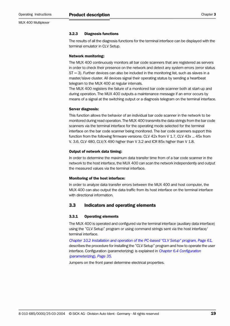
3.2.3 Diagnosis functions
The results of all the diagnosis functions for the terminal interface can be displayed with the
terminal emulator in CLV Setup.
Network monitoring:
The MUX 400 continuously monitors all bar code scanners that are registered as servers
in order to check their presence on the network and detect any system errors (error status
ST = 3). Further devices can also be included in the monitoring list, such as slaves in a
master/slave cluster. All devices signal their operating status by sending a heartbeat
telegram to the MUX 400 at regular intervals.
The MUX 400 registers the failure of a monitored bar code scanner both at start-up and
during operation. The MUX 400 outputs a maintenance message if an error occurs by
means of a signal at the switching output or a diagnosis telegram on the terminal interface.
Server diagnosis:
This function allows the behavior of an individual bar code scanner in the network to be
monitored during read operation. The MUX 400 transmits the data strings from the bar code
scanners via the terminal interface for the operating mode selected for the terminal
interface on the bar code scanner being monitored. The bar code scanners support this
function from the following firmware versions: CLV 42x from V 1.7, CLV 43x ... 45x from
V. 3.6, CLV 480, CLV/X 490 higher than V 3.2 and ICR 85x higher than V 1.8.
Output of network data timing:
In order to determine the maximum data transfer time from of a bar code scanner in the
network to the host interface, the MUX 400 can scan the network independently and output
the measured values via the terminal interface.
Monitoring of the host interface:
In order to analyze data transfer errors between the MUX 400 and host computer, the
MUX 400 can also output the data traffic from its host interface on the terminal interface
with directional information.
3.3 Indicators and operating elements
3.3.1 Operating elements
The MUX 400 is operated and configured via the terminal interface (auxiliary data interface)
using the "CLV Setup" program or using command strings sent via the host interface/
terminal interface.
Chapter 10.2 Installation and operation of the PC-based “CLV Setup“ program, Page 61,
describes the procedure for installing the "CLV Setup" program and how to operate the user
interface. Configuration (parameterizing) is explained in Chapter 6.4 Configuration (parameterizing), Page 35.
Jumpers on the front panel determine electrical properties.
8 010 685/0000/25-03-2004 © SICK AG · Division Auto Ident · Germany · All rights reserved 19
Chapter 3 Operating Instructions
MUX 400 Multiplexer
Product description
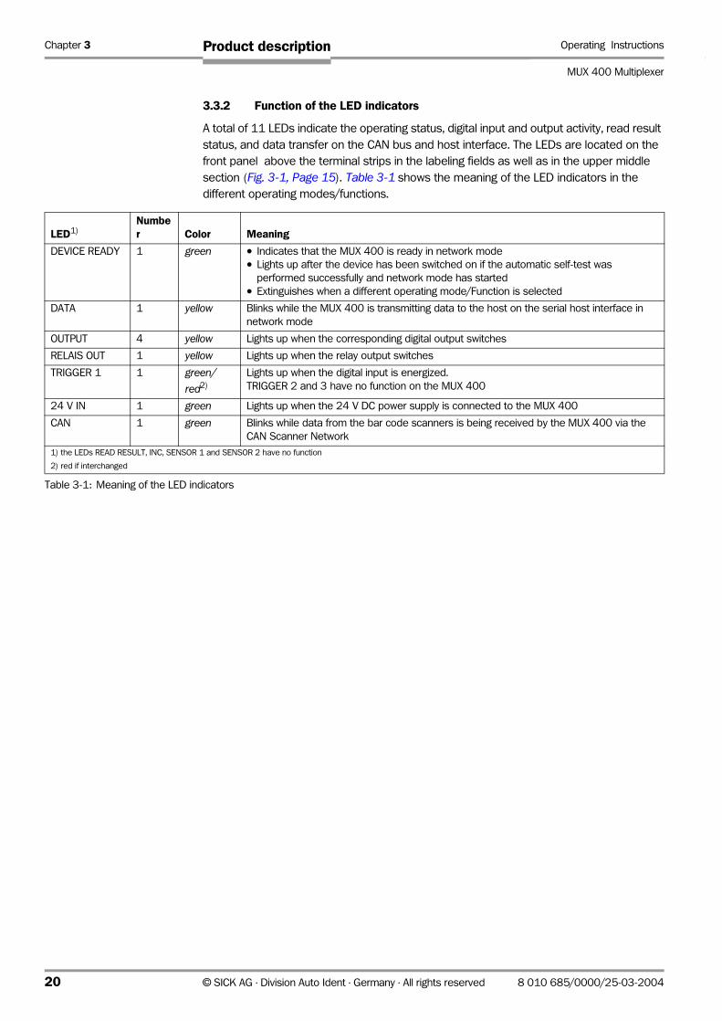
3.3.2 Function of the LED indicators
A total of 11 LEDs indicate the operating status, digital input and output activity, read result
status, and data transfer on the CAN bus and host interface. The LEDs are located on the
front panel above the terminal strips in the labeling fields as well as in the upper middle
section (Fig. 3-1, Page 15). Table 3-1 shows the meaning of the LED indicators in the
different operating modes/functions.
LED1)Number Color Meaning
DEVICE READY 1 green • Indicates that the MUX 400 is ready in network mode
• Lights up after the device has been switched on if the automatic self-test was
performed successfully and network mode has started
• Extinguishes when a different operating mode/Function is selected
DATA 1 yellow Blinks while the MUX 400 is transmitting data to the host on the serial host interface in
network mode
OUTPUT 4 yellow Lights up when the corresponding digital output switches
RELAIS OUT 1 yellow Lights up when the relay output switches
TRIGGER 1 1 green/
red2)
Lights up when the digital input is energized.
TRIGGER 2 and 3 have no function on the MUX 400
24 V IN 1 green Lights up when the 24 V DC power supply is connected to the MUX 400
CAN 1 green Blinks while data from the bar code scanners is being received by the MUX 400 via the
CAN Scanner Network
1) the LEDs READ RESULT, INC, SENSOR 1 and SENSOR 2 have no function
2) red if interchanged
Table 3-1: Meaning of the LED indicators
20 © SICK AG · Division Auto Ident · Germany · All rights reserved 8 010 685/0000/25-03-2004

Operating Instructions Chapter 4
MUX 400 Multiplexer
Installation
4 Installation
4.1 Selecting the installation site
• The MUX 400 (enclosure rating IP 20) is suitable for installation in an industry-type
control cabinet or control box on a top-hat rail. Alternatively it can be installed using the
mounting brackets.
• Regard the recommended maximum cable lengths in the CAN Scanner Network
(Table 5-5, Page 25)
• Regard the recommended maximum stub length between connection module and bar
code scanner (Table 5-6, Page 25)
• Regard the recommended cable length between MUX 400 and host (Table 5-8, Page 25)
• Access to the MUX 400 or to the connection module of a bar code scanner must be
possible at all times, as the access for parameterizing/diagnosis of the MUX 400 and
the network is carried out via a terminal interface (RS 232).
Max. cable length between MUX 400/bar code scanner and PC: 10 m (32.8 ft)
• If bar code scanners with optional heating are used, the MUX 400 must be installed
outside the cooling area due to its limited ambient temperature range of 0 ... +50 °C
(+32 to +122 °F)
• For hole and housing dimensions of the MUX 400, see Chapter 9.2 Dimensional drawings, Page 59
4.2 Installing the MUX 400
Damage to the devices in the control cabinet
Electronic devices in the control cabinet can be damaged by the discharge of static
electricity.
¾ Before opening the control cabinet, discharge your static electricity or wear a discharge
wrist strip.
1. Discharge static electricity or put on the a discharge wrist strip.
2. If necessary, switch of power supply for the control cabinet.
3. Ground the control cabinet or the top-hat rail.
4. Remove both mounting brackets on the MUX 400 for mounting the device onto the top-
hat rail.
5. Put the MUX 400 onto the top-hat rail in the control cabinet and lock the snap-in
brackets.
6. Ground the MUX 400 (e. g. using the grounding contact on the back side).
7. Connect the CAN Scanner Network.
4.3 Removing the device
1. Switch off the power supply of the MUX 400.
2. Remove all connectors and pluggable terminal strips from the MUX 400.
3. Remove the MUX 400 from the top-hat rail respectively unscrew the mounting
brackets.
When removing the device from service for the last time, please dispose of it in an
environmentally-friendly manner, as described in Chapter 7.3 Disposal, Page 51.
8 010 685/0000/25-03-2004 © SICK AG · Division Auto Ident · Germany · All rights reserved 21

Chapter 5 Operating Instructions
MUX 400 Multiplexer
Electrical installation
5 Electrical installation
5.1 Overview of the connection sequence
• Install and connect the bar code scanners in the CAN Scanner Network
• Connect the network to the CAN interface of the MUX 400
• Connect the host to the host interface of the MUX 400
• Connect the digital inputs and outputs of the MUX 400 (if required)
• Connect the MUX 400 to the power supply
• Connect the PC to MUX 400 (terminal interface)
5.2 Electrical connections and cables
The electrical connections for the MUX 400 consists of 10 pluggable screw terminal strips
and two 9-pin D Sub connectors. They are positioned on the front panel grouped in fields
with corresponding signs.
They supply the following interfaces:
Pluggable terminal strips
• one CAN interface, for connecting to the CAN Scanner Network
• one serial host interface (RS 422 or RS 232), for connecting to the host computer
• one serial terminal interface (RS 232), for connecting to the PC (configuration and
diagnosis)
• one digital input (external reading pulse), floating
• three digital outputs (for indicating the operating status, for connecting e. g. to PLC)
• one relay output (for indicating the operating status)
• power supply
D Sub connectors
• 9-pin D Sub plug “AUX“: host interface/terminal interface as above
• 9-pin D Sub socket “CAN“: CAN interface, for testing and diagnosis
¾ Wire all connections with copper cables with the following wire diameters:
– to CAN Scanner Network: see Table 5-7, Page 25
– host interface, terminal interface, digital input/outputs: at least 0.14 mm2 (26 AWG)
– relay output: at least 1 mm2 (18 AWG)
– power supply: depends on the number of bar code scanners to be supplied
¾ terminal strips: strip the wires of the cables to be connected approx. 5 mm (0.2 in).
Recommendation Use wire-end ferrules for the wires of flexible cables.
Specification of the terminal strips
Terminal strip Connection cable Wire diameter
“CAN“, “HOST“, “AUX“ fixed/flexible 0.14 to 1.5 mm2 (26 to 16 AWG)
Digital input/outputs “TRIGGER 1“ and “OUTPUT“ fixed/flexible 0.14 to 1.5 mm2 (26 to 16 AWG)
Relay output “RELAIS OUT“ fixed/flexible 0.2 ... 2.5 mm2 (24 to 14 AWG)
“24 V IN“ power supply rigid/flexible 0.2 ... 2.5 mm2 (24 to 14 AWG)
Table 5-1: Admissible wire diameters on the terminal strips
22 © SICK AG · Division Auto Ident · Germany · All rights reserved 8 010 685/0000/25-03-2004
Operating Instructions Chapter 5
MUX 400 Multiplexer
Electrical installation
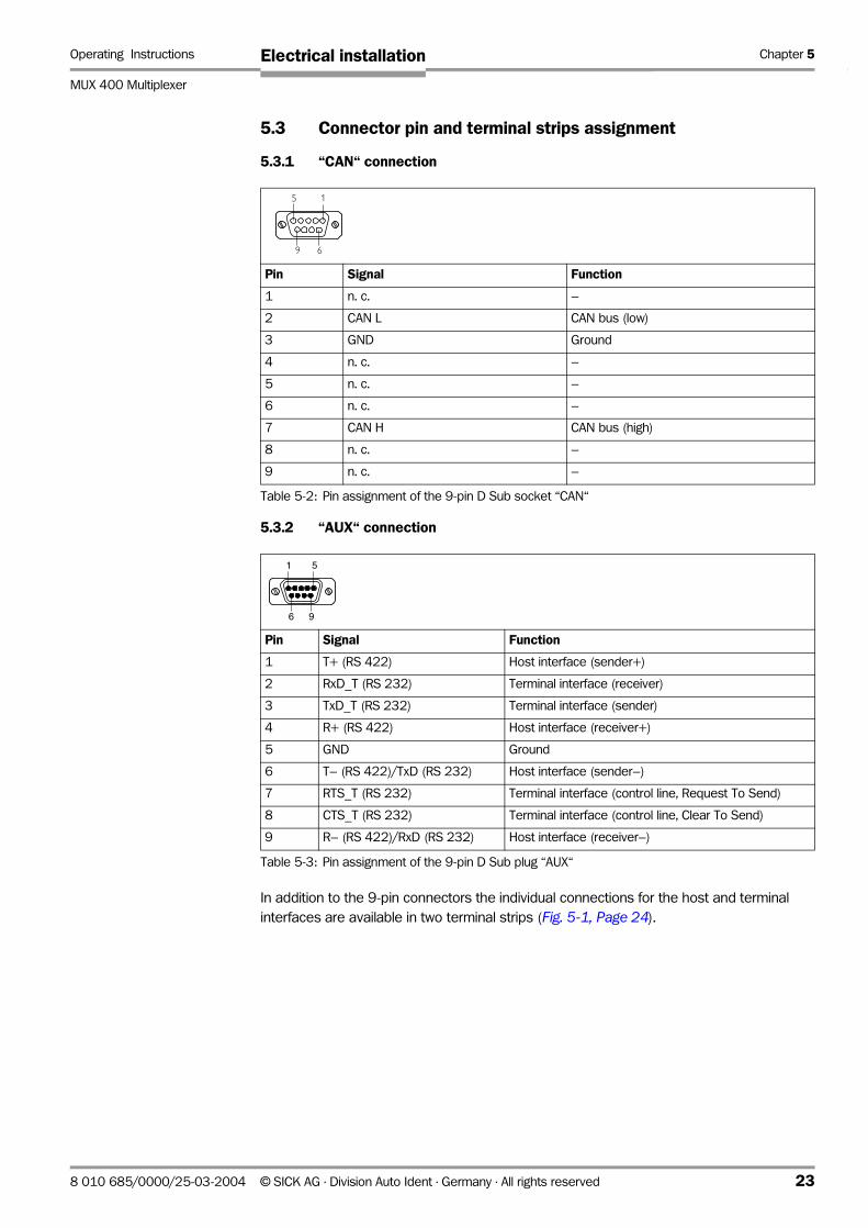
5.3 Connector pin and terminal strips assignment
5.3.1 “CAN“ connection
5.3.2 “AUX“ connection
In addition to the 9-pin connectors the individual connections for the host and terminal
interfaces are available in two terminal strips (Fig. 5-1, Page 24).
Pin Signal Function
1 n. c. –
2 CAN L CAN bus (low)
3 GND Ground
4 n. c. –
5 n. c. –
6 n. c. –
7 CAN H CAN bus (high)
8 n. c. –
9 n. c. –
Table 5-2: Pin assignment of the 9-pin D Sub socket “CAN“
Pin Signal Function
1 T+ (RS 422) Host interface (sender+)
2 RxD_T (RS 232) Terminal interface (receiver)
3 TxD_T (RS 232) Terminal interface (sender)
4 R+ (RS 422) Host interface (receiver+)
5 GND Ground
6 T– (RS 422)/TxD (RS 232) Host interface (sender–)
7 RTS_T (RS 232) Terminal interface (control line, Request To Send)
8 CTS_T (RS 232) Terminal interface (control line, Clear To Send)
9 R– (RS 422)/RxD (RS 232) Host interface (receiver–)
Table 5-3: Pin assignment of the 9-pin D Sub plug “AUX“
5 1
9 6
51
96
8 010 685/0000/25-03-2004 © SICK AG · Division Auto Ident · Germany · All rights reserved 23
Chapter 5 Operating Instructions
MUX 400 Multiplexer
Electrical installation
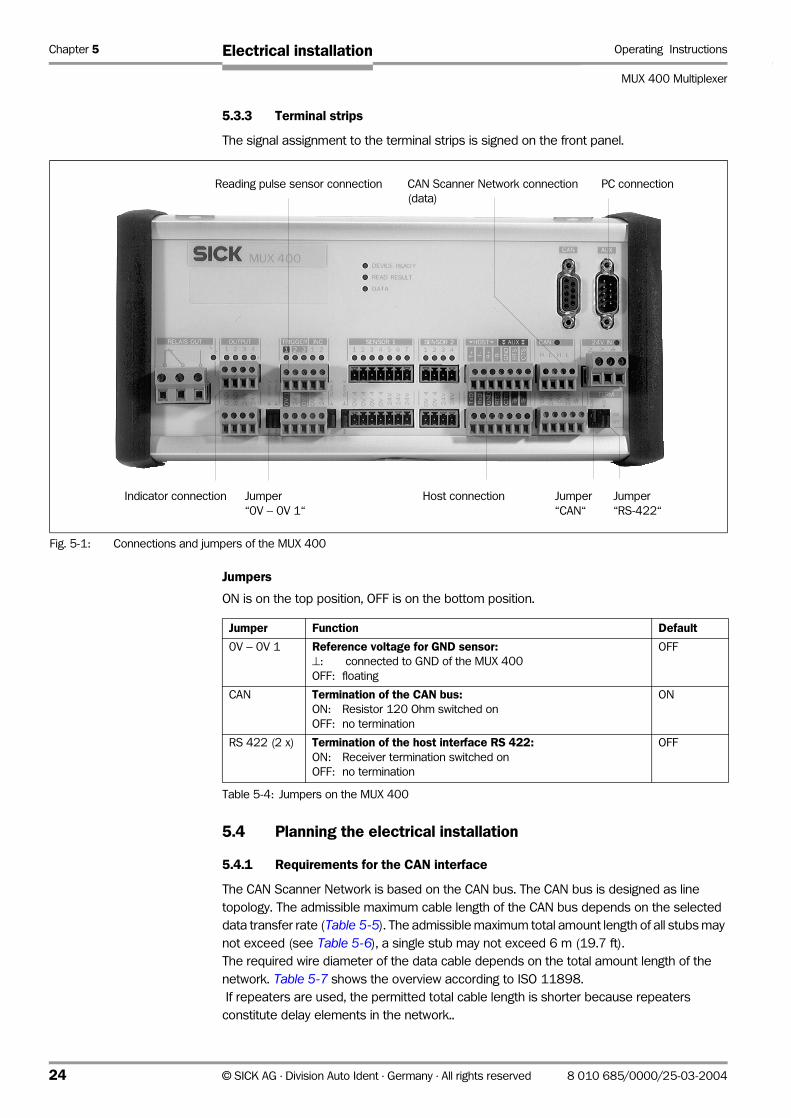
5.3.3 Terminal strips
The signal assignment to the terminal strips is signed on the front panel.
Jumpers
ON is on the top position, OFF is on the bottom position.
5.4 Planning the electrical installation
5.4.1 Requirements for the CAN interface
The CAN Scanner Network is based on the CAN bus. The CAN bus is designed as line
topology. The admissible maximum cable length of the CAN bus depends on the selected
data transfer rate (Table 5-5). The admissible maximum total amount length of all stubs may
not exceed (see Table 5-6), a single stub may not exceed 6 m (19.7 ft).
The required wire diameter of the data cable depends on the total amount length of the
network. Table 5-7 shows the overview according to ISO 11898.
If repeaters are used, the permitted total cable length is shorter because repeaters
constitute delay elements in the network..
Fig. 5-1: Connections and jumpers of the MUX 400
Jumper
“0V − 0V 1“
PC connectionCAN Scanner Network connection
(data)
Host connection Jumper
“CAN“
Jumper
“RS-422“
Reading pulse sensor connection
Indicator connection
Jumper Function Default
0V − 0V 1 Reference voltage for GND sensor:⊥: connected to GND of the MUX 400
OFF: floating
OFF
CAN Termination of the CAN bus:ON: Resistor 120 Ohm switched on
OFF: no termination
ON
RS 422 (2 x) Termination of the host interface RS 422:ON: Receiver termination switched on
OFF: no termination
OFF
Table 5-4: Jumpers on the MUX 400
24 © SICK AG · Division Auto Ident · Germany · All rights reserved 8 010 685/0000/25-03-2004

Operating Instructions Chapter 5
MUX 400 Multiplexer
Electrical installation
5.4.2 Requirements for the host interface
The host interface of the MUX 400 can be operated as an RS 422 or an RS 232 interface
Table 5-8 shows the recommended maximum cable lengths as a function of the selected
data transfer rate.
.
Recommendation To prevent interference, do not lay the cable between the MUX 400 and the bar code
scanners as well as the host parallel with power supply and motor cables over long
distances, e.g. in cable ducts.
Connecting the MUX 400 to field bus systems:
For connecting theMUX 400 to the field bus “Profibus-DP“ or “DeviceNet“ field bus
gateways are available for mounting on top-hat-rail. The MUX 400 is connected to the
gateway via the RS 232 interface.
Data transfer rate Maximum data cable length
10 kbit/s 5,000 m (16,404 ft)
20 kbit/s 2,500 m (8,202 ft)
50 kbit/s 1,000 m (3,280 ft)
100 kbit/s 600 m (1,968.5 ft)
125 kbit/s 500 m (1,640.4 ft)
250 kbit/s1) 250 m (820.2 ft)
500 kbit/s 100 m (32.8 ft)
1 Mbit/s 10 m (3.28 ft)
1) default setting of the MUX 400 and the bar code scanners
Table 5-5: CAN bus: Maximum cable length as a function of the data transfer rate
Data transfer rate Maximum total amount of all stub lengths
125 kbit/s 156 m (511.8 ft)
250 kbit/s 78 m (255.9 ft)
500 kbit/s 39 m (127.95 ft)
Table 5-6: CAN bus: Maximum stub lengths as a function of the data transfer rate
Cable length Required wire diameter (data cable)
0 to 40 m (0 to 131.2 ft) ≥ 0.25 mm2 (24 AWG)
40 to 300 m (131.2 to 984.2 ft) ≥ 0.34 mm2 (22 AWG)
300 to 600 m (984.2 to 1,968.5 ft) ≥ 0.5 mm2 (22 AWG)
600 to 1,000 m (1,968.5 to 3,280.8 ft) ≥ 0.75 mm2 (20 AWG)
Table 5-7: CAN bus: Required wire diameter as a function of the data cable length
Interface type Transfer rate Distance from host
RS 422*) max. 38,400 bd
max. 57,600 bd
max. 1,000 m (3,280.8 ft)
max. 500 m (1,640 ft)
RS 232 up to 19,200 bd
38,400 to 57,600 bd
max. 10 m (32.8 ft)
max. 3 m (9.84 ft)
*) with suitable line termination
Table 5-8: Maximum cable lengths between MUX 400 and host
8 010 685/0000/25-03-2004 © SICK AG · Division Auto Ident · Germany · All rights reserved 25
Chapter 5 Operating Instructions
MUX 400 Multiplexer
Electrical installation
5.4.3 Power supply
The MUX 400 requires a power supply of 24 V DC +20 %/−10 %(functional extra-low
voltage) in accordance with the standard IEC 364-4-41. The functional extra-low voltage
can be generated by using a safety isolating transformer pursuant to IEC 742. The MUX 400
has a power consumption of max. 5 W (when all digital outputs are connected).
The output circuit of the power supply must be reliably electrically isolated from the input circuit. To do so, use a safety isolating transformer pursuant to IEC 742
The core cross-section for the power supply of the MUX 400 should be a minimum of
0.2 mm2 (24 AWG). If the bar code scanners are powered via the MUX 400 (power supply
through-connected), the core cross-section to the MUX 400 and from the MUX 400 to the
bar code scanners is dependent on their power consumption and the cable length in the
network and the voltage drop .
5.5 Making electrical connections
5.5.1 Connecting the power supply
¾ Connect the power supply (24 V DC) to the terminal strip in the field „24 V IN“.
¾ Only switch on the power supply after connecting all required interfaces.
Note The input for power supply is interchangeable. Note that if the polarity of the supply voltage
is reversed, it is also reversed at the reading pulse sensor input, for the power supply of the
loads at the switching outputs, and for the power supply to the bar code scanners .
Connecting the power supply to the bar code scanners:
Risk of damage to the MUX 400
Components can be damaged by excessive supply currents at the wrong terminals.
¾ If the power supply for the bar code scanners is connected through the MUX 400 , the
supply voltage for the bar code scanners should only be picked up in the CAN field at
the “24 V” and “0 V” terminals on the lower terminal strip.
The required wiring diameters for the currents are only provided here.
5.5.2 Connecting the CAN interface to the network
1. For wiring the CAN Scanner Network use only a CAN bus specified cable, e. g.
no. 6 027 048 (2 x 2 wires 0.5 mm2 (22 AWG), twisted pair, shielded, wave resistor
120 Ω).2. Terminate the bus cable on both cable ends in the connection module using each a
termination resistor of 120 Ω. If the MUX 400 is at the end of the cable, switch on the
resistor using the jumper “CAN“ (default setting: ON). If the MUX 400 is not at the end,
switch off the termination (position: OFF).
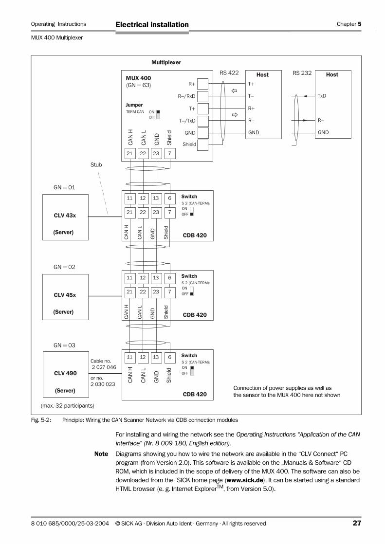
3. Connect the data cable of the network to the terminal strip on top of the field “CAN“.
Fig. 5-2 shows the principle of wiring the data cable via the CDB 420 connection
modules.
26 © SICK AG · Division Auto Ident · Germany · All rights reserved 8 010 685/0000/25-03-2004
Operating Instructions Chapter 5
MUX 400 Multiplexer
Electrical installation
For installing and wiring the network see the Operating Instructions “Application of the CAN interface“ (Nr. 8 009 180, English edition).
Note Diagrams showing you how to wire the network are available in the “CLV Connect“ PC
program (from Version 2.0). This software is available on the „Manuals & Software“ CD
ROM, which is included in the scope of delivery of the MUX 400. The software can also be
downloaded from the SICK home page (www.sick.de). It can be started using a standard
HTML browser (e. g. Internet ExplorerTM, from Version 5.0).
Fig. 5-2: Principle: Wiring the CAN Scanner Network via CDB connection modules
HostMUX 400(GN = 63) R+
R–/RxD
JumperTERM CAN
OFF
ON
CDB 420
RS 232
CLV 43x
GN = 03
CLV 490
21
GN = 01
(max. 32 participants)
(Server)
T+
T–/TxD
Shield
RS 422
GND
T+
T–
R+
R–
GND
Host
TxD
R–
GNDC
AN
H
CA
N L
GN
D
Shie
ld
SwitchS 2 (CAN-TERM):
OFF
ON
CA
N H
CA
N L
GN
D
Shie
ld
22 23 7
11 12 13 6
21 22 23 7
CDB 420
SwitchS 2 (CAN-TERM):
OFF
ON
11 12 13 6
21 22 23 7
Multiplexer
CDB 420
SwitchS 2 (CAN-TERM):
OFF
ON
11 12 13 6
CLV 45x
GN = 02
(Server)
(Server)
Stub
Cable no.
2 027 046
CA
N H
CA
N L
GN
D
Shie
ld
CA
N H
CA
N L
GN
D
Shie
ld
or no.
2 030 023Connection of power supplies as well as
the sensor to the MUX 400 here not shown
8 010 685/0000/25-03-2004 © SICK AG · Division Auto Ident · Germany · All rights reserved 27
Chapter 5 Operating Instructions
MUX 400 Multiplexer
Electrical installation
5.5.3 Connecting the CAN interface (9-pin D Sub socket)
This interface is used to connect a PC with CAN interface for testing and diagnosis.
Pin assignment see Table 5-2, Page 23.
5.5.4 Connecting the host interface
Risk of damage to the interface module
Electronic components in the MUX 400 may be damaged if the host interface is connected
incorrectly.
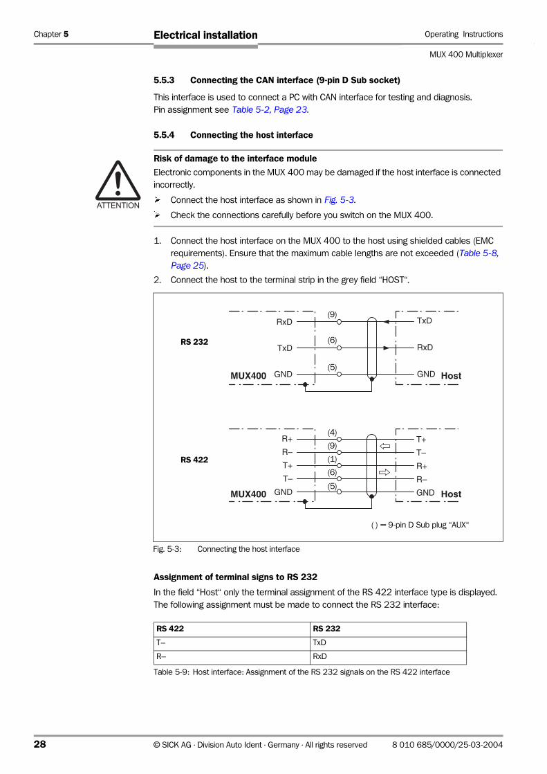
¾ Connect the host interface as shown in Fig. 5-3.
¾ Check the connections carefully before you switch on the MUX 400.
1. Connect the host interface on the MUX 400 to the host using shielded cables (EMC
requirements). Ensure that the maximum cable lengths are not exceeded (Table 5-8, Page 25).
2. Connect the host to the terminal strip in the grey field “HOST“.
Assignment of terminal signs to RS 232
In the field “Host“ only the terminal assignment of the RS 422 interface type is displayed.
The following assignment must be made to connect the RS 232 interface:
Fig. 5-3: Connecting the host interface
RxD
TxD
GND
R+
R–
T+
T–
GND
TxD
RxD
GND
T+
T–
R+
R–
GND
Host
Host
MUX400
MUX400
RS-232
RS-422
(9)
(6)
(5)
(4)
(1)
(5)
(9)
(6)
( ) = 9-pin D Sub plug “AUX“
RS 232
RS 422
RS 422 RS 232
T– TxD
R– RxD
Table 5-9: Host interface: Assignment of the RS 232 signals on the RS 422 interface
28 © SICK AG · Division Auto Ident · Germany · All rights reserved 8 010 685/0000/25-03-2004

Operating Instructions Chapter 5
MUX 400 Multiplexer
Electrical installation
Termination of the RS 422 interface
To improve the signal-to-noise ratio the receiver of the MUX 400 can be terminated.
¾ On the front panel, set the two jumpers in the field “TERM“ to position “ON“
(see also Table 5-4, Page 24).
In the default setting , the MUX 400 communicates with the host via the host interface using
the communication parameter values as shown in Table 5-10.
Activating the RS 232 interface
The RS 232 interface can be activated with the CLV Setup program:
1. Choose the HOST INTERFACE tab.
2. Choose the "RS 232" option from the HARDWARE drop-down list under DATA FORMAT.
3. Perform a download to the MUX 400. This is done by clicking in the toolbar.
The DOWNLOAD PARAMETER dialog window is displayed.
4. Confirm the dialog window by selecting the PERMANENT save option.
The MUX 400 uses the RS 232 type of the host interface.
TIP The communication parameters can be changed, if necessary, on the HOST INTERFACE tab.
To do so, change the values under DATA FORMAT and INTERFACE PROTOCOL.
5.5.5 Connecting the terminal interface
The MUX 400 is configured with the “CLV Setup” program. In order to do so, you must
connect the device to the PC via the terminal interface (auxiliary interface). Unlike the host
interface, the terminal interface has a permanent data format and a fixed data transfer rate.
Fig. 5-4 shows how the terminal interface is connected. The cable length is not to exceed
10 m (32.8 ft).
Parameter Value
Interface type RS 422
Data transfer rate 9,600 bd
Data bits 8
Parity no
Stop bits 1
Protocol SICK (start character: STX, stop character: ETX, handshake: NAK,
Timeout: 50 ms )
Table 5-10: Communication parameters of the host interface (default setting)
Fig. 5-4: Connecting the terminal interface
RS-232
“AUX”
RxD
TxD
GND
TxD
RxD
GND HostOPS
2
3
5
(3)
(2)
(5)PCMUX 400
( )= 9-pin D Sub
plug at PC
8 010 685/0000/25-03-2004 © SICK AG · Division Auto Ident · Germany · All rights reserved 29
Chapter 5 Operating Instructions
MUX 400 Multiplexer
Electrical installation
Risk of damage to the interface module
Electronic components in the MUX 400 may be damaged if the terminal interface is
connected incorrectly.
¾ Connect the terminal interface as shown in Fig. 5-4.
¾ Check the connections carefully before you switch on the MUX 400.
1. Switch off the PC.
2. Connect the PC to the 9-pin D Sub plug “AUX“.
To do so, use a 3-core RS 232 data cable (null modem cable), RxD and TxD crossed,
e. g. no. 2 014 054.
– or –Connect the PC with an corresponding RS 232 data cable (open end) to the terminal
strip in the blue field “AUX“.
3. Switch on the PC and start CLV Setup.
4. Set the communication parameters in the PC (see Chapter 10.2.3 Starting “CLV Setup“, Page 64).
In the default setting, the MUX 400 communicates via the terminal interface using the fixed
communication parameter values as shown in Table 5-11.
Tip In the default setting, the terminal interface outputs the read result in "MUX Diagnosis"
mode.
Via the AUXILIARY INTERFACE tab in the CLV Setup program you can change the operating
mode to “Server Diagnosis“ for a selected bar code scanner, to “Monitor Host Interface“
(MUX 400), or to “MUX Data Timing“ to output the taken maximum data transfer time (from
bar code scanner to the host interface).
5.5.6 Connecting the digital input “TRIGGER 1“
If the MUX 400 is to distribute the reading pulse in the network, the external read trigger
sensor can be connected to the “TRIGGER 1” digital input. The reading pulse signal will be
forwarded by the MUX 400 to the bar code scanners via the CAN bus. This trigger type is
selected in the default setting of the MUX 400. Fig. 5-5 shows the connection diagram for
the input, which is floating in the default setting (jumper “0V – 0V 1“ opened). Table 5-12
contains the characteristic data for this input.
Parameter Value
Interface type RS 232
Data transfer rate 9,600 bd
Data bits 8
Parity no
Stop bits 1
Protocol Start character: STX, Stop character: ETX
Table 5-11: Communication parameters of the terminal interface
30 © SICK AG · Division Auto Ident · Germany · All rights reserved 8 010 685/0000/25-03-2004
Operating Instructions Chapter 5
MUX 400 Multiplexer
Electrical installation
¾ Connect the reading pulse sensor to the terminal strip in the blue field “TRIGGER 1“ as
shown in Fig. 5-5.
The corresponding LED lights up (green) when the input signal (reading pulse signal) is
pending. If the input signal is interchanged, the LED lights red to indicate the fault.
The “0V – 0V 1“ jumper nearby the field “TRIGGER“ is used to connect the ground potential
of the reading pulse sensor “TRIGGER 1“ with the ground potential of the MUX 400 (top
position „⊥" of the jumper), if the sensor is to be powered via the MUX 400. The power
supply voltage (24 V DC) is available on the terminal strips in the field “TRIGGER“ (terminals
“24 V“ and “0 V 1“ (blue)). If the sensor is powered by an external power supply, the external
potential should be connected to the reading pulse sensor (bottom position of the jumper).
See also Table 5-4, Page 24.
Tip You can change the switching mode (polarity, debouncing, response for first pulse after
power-up) of the “TRIGGER 1“ input on the DEVICE CONFIGURATION tab in the CLV Setup
program.
¾ Edit the corresponding options in the NETWORK TRIGGER section.
Download all changes to MUX 400.
5.5.7 Connecting the outputs
The four digital outputs and the relay output (single-break and-make) can be assigned to the
status indication “Device Ready“ or “System Ready“ independently of each other:
– "Device Ready": If the MUX 400 is ready for operation after power-up, the corres-
ponding output becomes live and the relay switches the contact. If there a malfunction
occurs in the MUX 400 during operation, the output is deactivated and the relay de-
energizes.
Fig. 5-5: Connecting the digital input “TRIGGER 1“
Switching mode Default setting: current at the input starts the reading interval for all bar code
scanners in the network (active high, debouncing: 20 ms)
Properties digital, optodecoupled, non-interchangeable, debouncing 5 to 10,000 ms
(can be set)
can be connected to PNP output on a sensor
Electrical values(level)
Low: –10 V ≤ Uin ≤ +10 V; –3 mA ≤ Iin ≤ +3 mA
High: –30 V ≤ Uin ≤ –15 V; –10 mA ≤ Iin ≤ –5 mA
High: +30 V ≤ Uin ≤ +15 V; +10 mA ≤ Iin ≤ +5 mA
Table 5-12: Characteristic data of the digital input “TRIGGER 1“
2,67k X
0V–0V 1
GND
24 VVs
GND
PNP-Sensor
Vs
OUT
GND
MUX 400
Uin
Uinmax = 30 V!
Trigger 1
8 010 685/0000/25-03-2004 © SICK AG · Division Auto Ident · Germany · All rights reserved 31
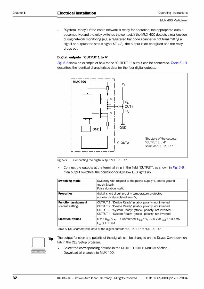
Chapter 5 Operating Instructions
MUX 400 Multiplexer
Electrical installation
– "System Ready": If the entire network is ready for operation, the appropriate output
becomes live and the relay switches the contact. If the MUX 400 detects a malfunction
during network monitoring (e.g. a registered bar code scanner is not transmitting a
signal or outputs the status signal ST = 3), the output is de-energized and the relay
drops out.
Digital outputs “OUTPUT 1 to 4”
Fig. 5-6 show an example of how to the “OUTPUT 1” output can be connected. Table 5-13
describes the identical characteristic data for the four digital outputs.
¾ Connect the outputs at the terminal strip in the field “OUTPUT“, as shown in Fig. 5-6.
If an output switches, the corresponding yellow LED lights up.
Tip The output function and polarity of the signals can be changed on the DEVICE CONFIGURATION
tab in the CLV Setup program.
¾ Select the corresponding options in the RESULT OUTPUT FUNCTIONS section.
Download all changes to MUX 400.
Fig. 5-6: Connecting the digital output “OUTPUT 1“
OUT1
OUT2
GNDGND
RL
RL
UB
MUX 400
Structure of the outputs
“OUTPUT 2 ... 4“
same as “OUTPUT 1“
VS
Switching mode Switching with respect to the power supply VS and to ground
(push & pull)
Pulse duration: static
Properties digital, short-circuit-proof + temperature-protected
not electrically isolated from VS
Function assignment(default setting)
OUTPUT 1: “Device Ready“ (static), polarity: not inverted
OUTPUT 2: “Device Ready“ (static), polarity: not inverted
OUTPUT 3: “System Ready“ (static), polarity: not inverted
OUTPUT 4: “System Ready“ (static), polarity: not inverted
Electrical values 0 V ≤ Uout ≤ VS Guaranteed: Uout • VS –2.5 V at Iout ≤ 100 mA
Iout ≤ 100 mA
Table 5-13: Characteristic data of the digital outputs “OUTPUT 1“ to “OUTPUT 4“
32 © SICK AG · Division Auto Ident · Germany · All rights reserved 8 010 685/0000/25-03-2004

Operating Instructions Chapter 5
MUX 400 Multiplexer
Electrical installation
Recommendation ¾ To check the switching functions using a high-impedance digital voltmeter, power the
outputs.
This prevents incorrect voltage values/switching statuses from being displayed.
Relay output “RELAIS OUT“
Fig. 5-7 shows the connection diagram of the output “RELAIS OUT“. Table 5-14 describes
the characteristic data of the output.
¾ Connect the output on the terminal strip in the field “RELAIS OUT“.
If the relay operates, the corresponding yellow LED lights up.
Note Even high-quality relays suffer from wear and tear on the contacts. For this reason, we
recommended the relay output be used only for functions that require many switching
cycles. The max. current is 1.5 A.
According to manufacturer’s data:
Typical service life of a relay at a maximum load (220 V AC/8 A): 100 000 switching cycles.
Typical mechanical service life (without load): 30 000 000 switching cycles.
Fig. 5-7: Connection diagram of the output “RELAIS OUT“
K2
MUX 400
Switching mode Relay output, single-break and-make relay,
Pulse duration: static
Properties floating, short-circuit-proof
electrically isolated from VS
Function assignment(default setting)
“System Ready (static)“, polarity: not inverted
Electrical values Alternating voltage/direct voltage 0 V ≤ USwitch ≤ 250 V
according to VDE 0110 group C
Ioutmax = 1.5 A at 24 V DC
Ioutmax = 0.2 A at 250 V DC
Ioutmax = 1.5 A at 250 V AC
Table 5-14: Characteristic data of the output “RELAIS OUT“
8 010 685/0000/25-03-2004 © SICK AG · Division Auto Ident · Germany · All rights reserved 33

Chapter 6 Operating Instructions
MUX 400 Multiplexer
Operation
6 Operation
6.1 Overview of the starting up sequence
• Install the SICK CAN Scanner Network and connect the MUX 400
• Configure the bar coder scanners for network operating mode
• Start up the MUX 400 with the factory default settings
• Connect the PC to the MUX 400 and configure the MUX 400 as multiplexer for network
operating mode
6.2 Default setting
Table 6-1 shows an overview of the factory default settings of the MUX 400.
The default settings of the parameters are stored permanently both in the MUX 400 (ROM)
and in the CLV Setup database. They can be loaded into the RAM of the MUX 400 or
displayed on the tabs of CLV Setup at any time.
Restore the default setting in the MUX 400
1. Click in the toolbar.
CLV Setup loads the default settings from its internal database and displays them on
the tabs.
2. Perform a download to the MUX 400. This is done by clicking in the toolbar.
The DOWNLOAD PARAMETER dialog box is displayed.
3. Confirm the dialog box by selecting the PERMANENT save option.
Parameter Values
CAN interface
Data transfer rate 250 kbits/s
Device number (GN) 63
Server list (entered devices) 01
Host interface RS 422
Data transfer rate 9,600 bd
Data format 8 data bits, no parity, 1 stop bit
Protocol NAK; start character: STX, stop character: ETX; timeout 50 ms
Output format Single telegram
Prefix compatible to CLX no
Test string not active
Terminal interface RS 232; 9,600 bd; 8 data bits, no parity, 1 stop bit (values cannot be changed)
Function MUX diagnosis
Reading pulse source for network triggering Sensor input (TRIGGER 1), active high, debouncing 20 ms, first trigger: edge
Outputs OUTPUT 1 to 2: “Device Ready“ (static), OUTPUT 3 to 4: “System Ready“ (static)
RELAIS OUT: “System Ready“ (static)
Field bus gateway non
Table 6-1: Default settings of the MUX 400
34 © SICK AG · Division Auto Ident · Germany · All rights reserved 8 010 685/0000/25-03-2004

Operating Instructions Chapter 6
MUX 400 Multiplexer
Operation
Displaying and printing out complete default settings in CLV Setup
1. Choose FILE and SAVE AS, and enter a file name in the dialog window that appears.
CLV Setup saves the current settings in a configuration file "*.scl".
2. Click in the toolbar.
CLV Setup loads the default settings from its internal database and displays them on
the tabs.
3. Click in the toolbar.
The PRINT FILE dialog window is then displayed.
4. If desired, a comment can be entered in the input field for the header of the printout.
Confirm the dialog window with "OK".
The PRINT dialog window for configuring the printer is then displayed.
5. Edit the dialog window accordingly and confirm.
CLV Setup prints out all of the default settings in the form of a table. The header contains
the company and user names that were entered during the CLV Setup installation routine.
6.3 Operating modes/functions
Standard operating mode
• Network operating mode
For configuring
• Parameterization
For monitoring purpose/troubleshooting
• MUX diagnosis
• Server diagnosis
• MUX data timing
• Monitoring host interface
• Displaying operating data
6.4 Configuration (parameterizing)
The MUX 400 is configured for network operating mode in accordance with the application
in site. The factory default settings or an application-specific parameter set of the MUX 400
are in effect before changes are made.
The MUX 400 supports two configuration methods:
• Configuration via the PC software “CLV Setup“
• Configuration with command strings
See Chapter 10.3 Configuring the MUX 400 with command strings, Page 71.
8 010 685/0000/25-03-2004 © SICK AG · Division Auto Ident · Germany · All rights reserved 35
Chapter 6 Operating Instructions
MUX 400 Multiplexer
Operation
6.4.1 Configuring the MUX 400 with the user interface of CLV Setup
To be able to use "CLV Setup", a PC has to be connected and the program installed on it.
The procedure for connecting the PC to the MUX 400 is described in Chapter 5.5.5 Connecting the terminal interface, Page 29. Installation and startup of "CLV Setup" and
operation of the user interface are described in the appendix. See Chapter 10.2 Installation and operation of the PC-based “CLV Setup“ program, Page 61.
Transferring the parameter set between CLV Setup and the MUX 400
Upload
When the MUX 400 is being parameterized, CLV Setup runs in the offline mode. To be able
to modify the current parameter set of the MUX 400, this first has to be loaded to CLV Setup
from the MUX 400. This procedure is referred to as an upload ("Upload from MUX 400")
during which CLV Setup always loads a complete copy of the current MUX 400 parameter
set. This parameter set remains unchanged until it is overwritten by CLV Setup.
With the help of the context menu (right mouse button), only the parameter just edited can
be loaded ("Upload parameter") or from version 3.6 all parameters of one tab or one dialog
box ("Upload parameters of this view") from the MUX 400’s memory (RAM).
Download
Changes made to the current parameter set in CLV Setup do not take effect until the
parameter set has been transferred to the MUX 400. CLV Setup always sends a copy of the
complete parameter set to the MUX 400, i.e. all of the existing parameter values in the
MUX 400 are overwritten. The procedure for transferring and saving the parameter values
in the MUX 400 is referred to as a download ("Download to MUX 400").
With the help of the context menu (right mouse button), only the parameter just edited
("Download parameter") or from version 3.6 all parameters of one tab or one dialog box
("Download parameters of this view") will be temporarily loaded into the MUX 400’s
memory (RAM).
To finish the parametrization done by this way all parameters must be download again to
the MUX 400 with the "Permanent" option.
Loading complete parameter set from the MUX 400 (upload)
¾ Click in the toolbar.
CLV Setup loads the current MUX 400 parameter set from the RAM of the MUX 400 to
its database and displays the values on the tabs.
The "Device Ready" LED is extinguished during the upload.
If the "CLV Setup" program does not recognize the parameters transferred during the
upload, it outputs a warning. Unknown parameters can be edited on the EXTRAS tab by
following the conventions for command strings. When the parameter set is saved, these
parameters are also taken into account.
Transferring the complete parameter set to the CLV and saving it (download)
1. Click in the toolbar.
The "Device Ready" LED is extinguished.
CLV Setup copies the parameter set to the RAM of the MUX 400.
The DOWNLOAD PARAMETERS dialog window with the save options is then displayed.
PERMANENT: CLV Setup copies the parameter set to the RAM and to the EEPROM of
the MUX 400.
36 © SICK AG · Division Auto Ident · Germany · All rights reserved 8 010 685/0000/25-03-2004
Operating Instructions Chapter 6
MUX 400 Multiplexer
Operation
TEMPORARY: CLV Setup copies the parameter set to the RAM only. The changes are
lost when the MUX 400 power supply is switched off.
2. Confirm the dialog box with the desired save option.
The "Device Ready" LED lights up again.
The new parameter set is saved in the MUX 400, permanently or temporarily dependent on
the selected option.
Saving the parameter set in CLV Setup
1. To save the modified parameter set as a new configuration file in CLV Setup, or to
overwrite an existing file, choose FILE and SAVE AS.
The SAVE AS dialog window is then displayed.
2. Enter the file name in the dialog window (file extension "*.scl") and confirm the entry.
The new parameter set is now saved in CLV Setup in the subdirectory "data"
8 010 685/0000/25-03-2004 © SICK AG · Division Auto Ident · Germany · All rights reserved 37
Chapter 6 Operating Instructions
MUX 400 Multiplexer
Operation
6.4.2 Function of the tabs in CLV Setup (overview)
Device Configuration
This tab (and additional dialog windows) are used to set the following:
• Source of the reading pulse for the network (network trigger)
• Functional assignment of the digital outputs
Host Interface
This tab (and additional dialog windows) are used to set the following:
• Active physical interface (RS 422, RS 232)
• Data format and transfer rate
• Data transfer protocol
• Start and stop characters of the interface protocol
• Protocol timeout
Data Strings
This tab (and additional dialog windows) are used to set the following:
• Data output format of the host interface (single/block telegram)
• Constants and reading diagnosis data in the Separator
• Test string function
• Prefix compatible with CLX 200 Network Controller
Auxiliary Interface
This tab is used to set the following:
• Operating mode of the terminal interface
CAN Interface
This tab (and additional dialog windows) are used to set the following:
• Device number
• Data transfer rate
• Entry of the bar code scanners in the server list
• Bar code scanners to be additionally guarded
Fieldbus Gateway
This tab (and additional dialog windows) are used to set the following:
• Data interface of the MUX 400 to be connected to the gateway
• Type of field bus
• Special fieldbus parameters
Extras
This tab is used to edit parameters that were not recognized by CLV Setup after an upload
from the MUX 400.
Note The online "CLV Setup Help" contains a detailed description of the functions of the
parameters and their valid entries. See Chapter Online CLV Setup Help, Page 62.
38 © SICK AG · Division Auto Ident · Germany · All rights reserved 8 010 685/0000/25-03-2004
Operating Instructions Chapter 6
MUX 400 Multiplexer
Operation
6.4.3 Parameterization guide
The MUX 400 can also be configured as a multiplexer via remote access with a bar code
scanner in the network. For this purpose, the network communication parameters must be
identical (with the exception of the device numbers) and a project must be created in CLV Setup to logically organize the network and ensure that the MUX 400 can be addressed via
a communication channel.
See Operating instructions “Application of the CAN interface“ (Nr. 8 009 180, English edition).
Note To following the remaining instructions for configuring the MUX 400, connect the PC directly
to the MUX 400.
Prerequisites for parameterization:
• The CAN interfaces of the bar code scanners and MUX 400 are connected via a
twisted-pair cable. Both bus ends are terminated with 120 Ω resistors (in the
connection module or the MUX 400 itself).
• Each bar code scanner and the MUX 400 must be assigned a unique device number
from 1 to 63. With the CMC 400 cloning module, device numbers from 1 to 63 as well
as the data transfer rate/CAN operating mode for the bar code scanners can be
permanently set in the CDB/CDM connection module.
• The CAN data transfer rate is identical in all bar code scanners and the MUX 400
(default setting: 250 kbit/s, note the maximum CAN data transfer rate, depending on
cable length, seeTable 5-5, Page 25).
• The “CAN Scanner Network” operating mode is activated in all bar code scanners.
• The supply voltage for all bar code scanners must be switched on.
Note The CAN interface and the device number of every bar code scanner must be configured
separately with CLV Setup if a CMC 400 module is not used. Every bar code scanner must
be connected individually to the PC for this purpose.
The CAN interface of the MUX 400 must first be configured before it can communicate with
the other devices in the network.
The procedures for organizing, installing, and configuring the CAN Scanner Network with bar
code scanners and connection modules should be carried out as described in the Operating Instructions “Application of the CAN interface”.
Preparations for parameterization:
1. Connect the PC to the terminal interface of the MUX 400.
To do so, connect a 3-core RS 232 data cable (null modem cable) to the 9-pin D Sub
plug “AUX“.
2. Switch on the power supply for the MUX 400.
3. Switch on the PC and install the “CLV Setup“ configuration software on the “Manuals &
Software“ CD ROM if you have not already done this.
4. Start the “CLV Setup“ software.
When it successfully establishes communication with the MUX 400, CLV Setup copies
the current parameter set and displays the values on the tabs.
5. Configure the MUX 400 as described below.
8 010 685/0000/25-03-2004 © SICK AG · Division Auto Ident · Germany · All rights reserved 39

Chapter 6 Operating Instructions
MUX 400 Multiplexer
Operation
Overview for the MUX 400:
• Configure the CAN interface and the assignment of the bar code scanners
• Configure the host interface and the format of the data strings
• Configure the network trigger via MUX 400 (if required)
• Configure the function of the outputs (if required)
• Configure the function of the terminal interface (e. g. guarding the network)
• Copy the parameter set to the MUX 400 (download)
6.4.4 Configuring the CAN interface of the MUX 400
¾ Choose the CAN INTERFACE tab.
¾ Set the following values on the tab:
• Device number: 01 to 63 (unique for all devices in the network)
• CAN data rate: 10 to 250 to 1,000 kbit/s (identical to the data rate on the
network)
• Server list: 01 to 63.
Click the device numbers of the bar code scanners to be
assigned as server to the MUX 400.
The selected devices are automatically included in the network
monitoring function by the MUX 400.
Optional:
• Guarding list: Click the numbers of the bar code scanner devices in the list
that are also to be monitored by the MUX 400 without
exchanging data directly with it (e.g. slaves in a master/slave
cluster).
The values in bold are the default settings.
Fig. 6-1: CLV Setup: “CAN Interface“ tab
40 © SICK AG · Division Auto Ident · Germany · All rights reserved 8 010 685/0000/25-03-2004

Operating Instructions Chapter 6
MUX 400 Multiplexer
Operation
6.4.5 Configuring the host interface of the MUX 400
¾ Choose the HOST INTERFACE tab.
¾ Set the following values on the tab according to the host to be connected:
• Baud rate: 1200 to 9,600 to 57,600 kbd
• Sto pbits: 1 or 2
• Data/parity bits: 8 bit/no parity to 7 bit/space parity
• Hardware: RS 422 or RS 232
• Interface protocol type: NAK (Standard) to ACK/NAK to No handshake
• Standard start character: Sending: STX NUL, Receiving: ETX NUL
• Standard stop character: Sending: STX NUL, Receiving: ETX NUL
• XON/XOFF: active/not active
• Block check: active/not active
• Protocol timeout: 0 to 50 to 9,999 ms
Optional:
• 3964 connection: 3964/low priority to 3964 (R)/high priority
• RK 512
The values in bold are the default settings.
XON/XOFF:
When the XON/XOFF protocol is active, the host can interrupt the data flow from the
MUX 400 by sending the control character "XOFF" to the MUX 400. If the MUX 400 then
receives the control character "XON", it resumes data transmission.
The MUX 400 only processes the control characters "XON" and "XOFF" at its host interface.
Fig. 6-2: CLV Setup: “Host Interface“ tab
8 010 685/0000/25-03-2004 © SICK AG · Division Auto Ident · Germany · All rights reserved 41

Chapter 6 Operating Instructions
MUX 400 Multiplexer
Operation
6.4.6 Configuring the data strings of the host interface
¾ Choose the DATA STRINGS tab.
¾ Set the following values on the tab:
• Output format: Single Telegram or Block Telegram.
See also Chapter 3.2.2 Output format of the host interface, Page 17
• Max. block length: for block telegram: 10 to 1,000 bytes (characters)
• Separator: for block telegram: max. 5 elements. Contain ASCII
characters (letters, digits) and control characters.
Separates the read results from the individual
bar code scanners (blocks) from each other in the data
string.
• Prefix CLX compatible: Yes/no (compatibility to CLX 200)
Yes: the MUX 400 does not insert a separator between the
device number and read result in the data string.
No: the MUX 400 inserts the separator “” (closing curly
bracket, 7D hex, default setting) between the device number
and the read result in the data string.
The separator can be changed by using the CNX hex value
command in the EXTRAS tab.
See Chapter 10.7 Code table (Hex – ASCII), Page 75.
Optional:
• Test string: max. 15 elements. Contain ASCII characters (letters, digits)
and control characters
• Interval: 1 to 300 to 9,999 s
The values in bold are the default settings.
Fig. 6-3: CLV Setup: “Data string“ tab
42 © SICK AG · Division Auto Ident · Germany · All rights reserved 8 010 685/0000/25-03-2004

Operating Instructions Chapter 6
MUX 400 Multiplexer
Operation
6.4.7 Configuring the network trigger (via MUX 400
¾ Choose the DEVICE CONFIGURATION tab.
¾ Set the following values on the tab according to the desired reading pulse type:
• Source: Sensor Input (active high) to Serial Interface.
The sensor input is the digital input “TRIGGER 1“.
Active high: the input switches when powered.
Active low: the input switches, when no signal is detected.
See also Chapter 5.5.6 Connecting the digital input “TRIGGER 1“, Page 30.
• First trigger: Edge or Level
• Debouncing Sensor: 5 to 20 to 10,000 ms
Optional:
• Serial Interface: Standard Trigger or Single Character
Note When the MUX 400 receives a pulse signal via the sensor input or serial interface (host or
terminal interface), it distributes this signal in the network. Bar code scanners that use this
signal to trigger their internal read gate must be set under the CAN INTERFACE tab in the PULSE
DISTRIBUTION section to the “receive read signal” option and the MUX 400 device number.
For more details about read pulse distribution in the network, see the Operating Instructions “Application of the CAN interface“.
Fig. 6-4: CLV Setup: “Device Configuration“ tab
8 010 685/0000/25-03-2004 © SICK AG · Division Auto Ident · Germany · All rights reserved 43

Chapter 6 Operating Instructions
MUX 400 Multiplexer
Operation
6.4.8 Configuring the function of the MUX 400 outputs
¾ Choose the DEVICE CONFIGURATION tab (Fig. 6-4, Page 43).
Set the following values on the tab according to the used outputs:
• Output 1 and 2: Device Ready (MUX 400) or System Ready (network)
• Output 3 and 4: Device Ready or System Ready
• Relay Output: Device Ready or System Ready
Optional:
• All outputs: Inverted.
When you choose this option, the appropriate output then
transmits a signal when the MUX 400 or the network are not operational.
Each of the outputs provide a static signal.
For connecting the outputs see Chapter 5.5.7 Connecting the outputs, Page 31.
6.4.9 Configuring the function of the MUX 400 terminal interface
The terminal interface has four functions for monitoring the network, diagnosing each
individual bar code scanner, outputting the data transfer time, and monitoring data traffic on
the host interface.
MUX Diagnosis:
In this mode, the terminal interface outputs the results of the continuous network
monitoring. These results can be displayed in the terminal emulator.
1. Choose the AUXILIARY INTERFACE tab.
2. Choose the MUX DIAGNOSIS option from the drop-down list.
3. Perform a download to the MUX 400 (not required in the default setting).
To do so, click the MUX DIAGNOSIS option again with the right mouse button and choose
DOWNLOAD PARAMETER in the context menu.
Fig. 6-5: CLV Setup: “Auxiliary interface“ tab: Selecting the MUX Diagnosis
44 © SICK AG · Division Auto Ident · Germany · All rights reserved 8 010 685/0000/25-03-2004
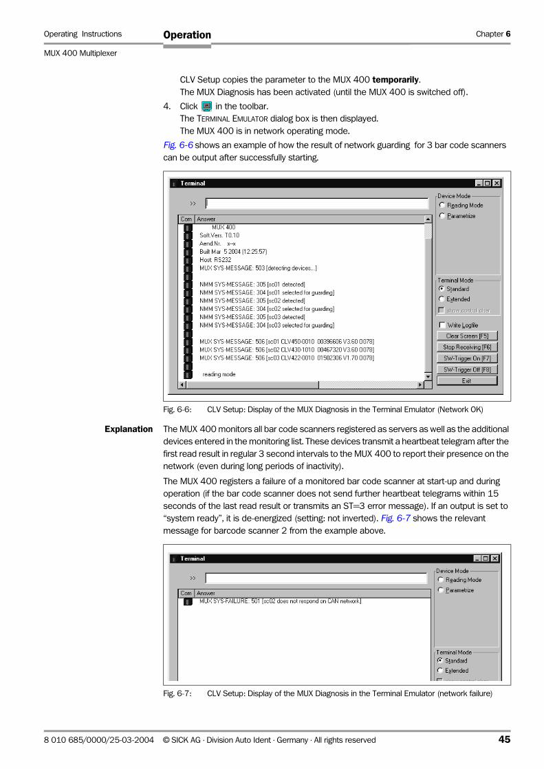
Operating Instructions Chapter 6
MUX 400 Multiplexer
Operation
CLV Setup copies the parameter to the MUX 400 temporarily.
The MUX Diagnosis has been activated (until the MUX 400 is switched off).
4. Click in the toolbar.
The TERMINAL EMULATOR dialog box is then displayed.
The MUX 400 is in network operating mode.
Fig. 6-6 shows an example of how the result of network guarding for 3 bar code scanners
can be output after successfully starting.
Explanation The MUX 400 monitors all bar code scanners registered as servers as well as the additional
devices entered in the monitoring list. These devices transmit a heartbeat telegram after the
first read result in regular 3 second intervals to the MUX 400 to report their presence on the
network (even during long periods of inactivity).
The MUX 400 registers a failure of a monitored bar code scanner at start-up and during
operation (if the bar code scanner does not send further heartbeat telegrams within 15
seconds of the last read result or transmits an ST=3 error message). If an output is set to
“system ready”, it is de-energized (setting: not inverted). Fig. 6-7 shows the relevant
message for barcode scanner 2 from the example above.
Fig. 6-6: CLV Setup: Display of the MUX Diagnosis in the Terminal Emulator (Network OK)
Fig. 6-7: CLV Setup: Display of the MUX Diagnosis in the Terminal Emulator (network failure)
8 010 685/0000/25-03-2004 © SICK AG · Division Auto Ident · Germany · All rights reserved 45

Chapter 6 Operating Instructions
MUX 400 Multiplexer
Operation
Server Diagnosis:
In this operating mode, the terminal interface of the MUX 400 outputs the data strings from
the terminal interface of a selected barcode scanner in the network. These depend on the
set operating mode of the terminal interface (e.g. read diagnosis). The data strings can be
displayed in the terminal emulator.
1. Choose the AUXILIARY INTERFACE tab.
2. Choose the SERVER DIAGNOSIS option from the drop-down list.
3. In the SERVER-ID field, edit the device number of the bar code scanner to be monitored.
4. Perform a download to the MUX 400.
To do so, click the tab with the secondary mouse button and select the DOWNLOAD
PARAMETERS OF THIS VIEW command from the context menu.
CLV Setup copies the parameters to the MUX 400 temporarily.
The Server Diagnosis is has been activated (until the MUX 400 is switched off).
Fig. 6-9 shows an example of how the read result of the bar code scanner no. 2 can be
output in the Server Diagnosis.
Fig. 6-8: CLV Setup: “Auxiliary interface“ tab: Selecting the Server Diagnosis
Fig. 6-9: CLV Setup: Display of the Server Diagnosis in the Terminal Emulator
46 © SICK AG · Division Auto Ident · Germany · All rights reserved 8 010 685/0000/25-03-2004

Operating Instructions Chapter 6
MUX 400 Multiplexer
Operation
MUX Data Timing:
In this operating mode, the terminal interface of the MUX 400 outputs the required data
transfer times for each bar code scanner in the network. These are the times for the transfer
of data strings of each signaling barcode scanner to the host interface of the MUX 400. The
analyzed times can be displayed in the terminal emulator.
1. Choose the AUXILIARY INTERFACE tab (see Fig. 6-5, Page 44).
2. Choose the MUX DATA TIMING option from the drop-down list.
3. Perform a download to the MUX 400.
To do so, click the MUX DATA TIMING option again with the right mouse button and
choose DOWNLOAD PARAMETER in the context menu.
CLV Setup copies the parameter to the MUX 400 temporarily.
The data transfer times are output until the MUX 400 is switched off.
Fig. 6-10 shows an example of how the data transfer time of a network with 3 bar code
scannern can be output.
Monitoring Host Interface:
In this mode, the MUX 400 outputs the data traffic of its host interface via the terminal
interface. Protocol driver handshakes and protocol-specific data, such as start and stop
characters, are suppressed here (Table 6-2). Each data string sent to the host by the
MUX 400 is displayed on a separate line on the screen with the mark “O“ (OUT).
Fig. 6-10: CLV Setup: Display of the data transfer time (MUX Data Timimg) in the Terminal Emulator
Direction of data Output format Representation on screen
MUX 400 receives from host <STX> I data <CR> <LF> <ETX> I data
MUX 400 sends to host <STX> O data <CR> <LF> <ETX> 0 data
Table 6-2: Monitoring host interface“ function
8 010 685/0000/25-03-2004 © SICK AG · Division Auto Ident · Germany · All rights reserved 47

Chapter 6 Operating Instructions
MUX 400 Multiplexer
Operation
1. Choose AUXILIARY INTERFACE tab (see Fig. 6-5, Page 44).
2. Choose the MONITOR HOST INTERFACE option from the drop-down list.
3. Perform a download to the MUX 400.
To do so, click the MONITOR HOST INTERFACE option again with the right mouse button and
choose DOWNLOAD PARAMETER in the context menu.
CLV Setup copies the parameter to the MUX 400 temporarily.
The data traffic on the host interface is output until the MUX 400 is switched off.
Fig. 6-11 shows an example of how the data traffic of the host interface can be output.
Note Large amounts of data received at high speeds via the host interface and high data transfer
rates may cause the flow of host interface traffic to no longer be completely displayed on
the terminal interface (display "…").
This is caused by the slower data transfer speed of the terminal interface (9,600 bd).
6.4.10 Downloading the parameter set and restarting the system
1. After configuring the MUX 400 via the tabs, copy the created parameter set to the
MUX 400 performing a download.
To do so, choose the icon in the toolbar.
The PARAMETER DOWNLOAD dialog box is displayed.
2. Confirm the dialog box by choosing the Permanent storage option.
3. Save the modified parameter set as a new configuration file in CLV Setup.
4. Test the installation.
Fig. 6-11: CLV Setup: Display of the data traffic on the host interface in the Terminal Emulator
48 © SICK AG · Division Auto Ident · Germany · All rights reserved 8 010 685/0000/25-03-2004

Operating Instructions Chapter 6
MUX 400 Multiplexer
Operation
6.5 Further operation steps
6.5.1 Displaying and editing operating data
This function enables statistical operating data, which the MUX 400 maintains in the form of
counters during the network operating mode, to be displayed. A user text for the
administration of the MUX 400 can be entried.
The MUX 400 does not output any data via the host interface in this mode.
1. Click in the toolbar.
The MUX 400 cancels network operating mode. The "Device Ready" LED is
extinguished.
The OPERATING DATA dialog box appears (Fig. 6-12).
2. After checking the desired counters, click "OK" to confirm the dialog box.
The MUX 400 returns to network operating mode. The "Device Ready" LED lights up.
6.6 MUX 400 messages
The MUX 400 outputs system and error messages in English via the terminal interface to
confirm user actions. The messages are output in the form of 3-digit codes with a message
text in parentheses.
6.6.1 Displaying messages
To display the messages on the PC in the CLV Setup user interface, proceed as follows:
¾ Click in the toolbar.
The terminal emulator window is then displayed.
6.6.2 System messages
System messages confirm the successful execution of a task, such as switching on and
starting the network. They are initiated by the following identifiers:
• MUX SYS-Message: xxx [text] (message of the MUX 400)
• NMM SYS-Message: xxx [text] (network management message )
No other actions are required here.
Fig. 6-12: CLV Setup: “Operating data“ dialog box
8 010 685/0000/25-03-2004 © SICK AG · Division Auto Ident · Germany · All rights reserved 49
Chapter 6 Operating Instructions
MUX 400 Multiplexer
Operation
6.6.3 Error rmessages
Error messages indicate errors on the network with the following identifiers:
• MUX SYS-Failure: xxx [text] (MUX 400 error)
• NMM SYS-Failure: xxx [text] (network management error)
• CLV SYS-Failure: xxx [text] (bar code scanner error)
The error messages indicate the cause of the problem and enable corrective measures to
be taken quickly.
6.7 Switching off the MUX 400
1. If the parameter set was modified in CLV Setup or was only stored temporarily in
MUX 400 via a download ("Temporary" option or via context menu (right mouse
button)), the parameter set must be stored permanently in the MUX 400 by choosing
the PERMANENT storage option.
2. Save parameter set as a "*.scl" configuration file in CLV Setup.
3. Switch off the power supply of the MUX 400 or pull the terminal strip “24 V IN“ from the
MUX 400.
The last parameter set stored permanently in the MUX 400 remains valid.
We recommend that you print out the configuration file in order to archive the parameter set.
1. Click in the toolbar.
The PRINT FILE dialog box is then displayed.
2. Enter a comment in the input field in order to assign the printout to the MUX 400.
Confirm the dialog box with "OK".
The PRINT dialog box for configuring the printer is then displayed.
3. Edit the dialog box accordingly and confirm.
CLV Setup prints out the current configuration file in the form of a table.
50 © SICK AG · Division Auto Ident · Germany · All rights reserved 8 010 685/0000/25-03-2004
Operating Instructions Chapter 7
MUX 400 Multiplexer
Maintencance
7 Maintencance
7.1 Cleaning the reading pulse sensor during operation
¾ If the network is triggered via the MUX 400 using an external reading pulse sensor
(e.g. a photoelectric switch), the optical surfaces should be cleaned regularly in
accordance with the operating environment.
Contamination can cause switching errors.
7.2 Maintenance
The MUX 400 operates maintenance-free. Its self-monitoring function ensures fault-free
operation over long periods of time.
When the network is monitored, the MUX 400 shows whether maintenance is necessary if
a fault occurs, either by means of a signal to a digital output set with the “system ready”
function or by sending a diagnosis telegram to the terminal interface.
The MUX 400 outputs internal errors as well as device errors and malfunctions on the bar
code scanners in the form of messages on the terminal interface. These can be displayed
on the PC screen in the Terminal Emulator in the CLV Setup program.
7.3 Disposal
Irreparable devices or devices that are no longer required are to be disposed of in an
environmentally-friendly manner:
1. Always observe the applicable national waste disposal regulations.
2. Remove the MUX 400 housing.
3. Remove the electronic modules and the cables.
4. Send the chassis (aluminium) to be recycled.
5. Send the plastics to be recycled.
6. Send the electronic modules and cables for disposal as special waste.
At present, SICK AG does not accept any unusable or irreparable devices.
8 010 685/0000/25-03-2004 © SICK AG · Division Auto Ident · Germany · All rights reserved 51
Chapter 8 Operating Instructions
MUX 400 Multiplexer
Troubleshooting
8 Troubleshooting
8.1 Overview of the possible errors and malfunctions
8.1.1 Electrical installation errors
• Supply voltage for the bar code scanners or MUX 400 is not connected
• Wiring errors in the CAN Scanner Network
• Interfaces of the MUX 400 connected incorrectly
8.1.2 Parameterization errors
• Wrong device address (doubled) in the network
• Communication parameters in the CAN Scanner Network configured incorrectly
• Communication parameters of the host interface configured incorrectly
8.1.3 Malfunctions during operation
• Device error of a bar code scanner in the CAN Scanner Network
• Device error (hardware/software) of the MUX 400
8.2 Monitoring error and malfunctions
• The MUX 400 is self-monitoring in operation.
After the power supply has been switched on, the MUX 400 automatically carries out a
self-test, in which it checks important hardware components, before it is initialized
(parameter set laoded and device functions initialized).
• The MUX 400 constantly monitors all bar code scanners registered in the system for
their presence on the network and also for any errors that may occur. This takes place
when the network is started and during operation.
8.3 Error messages
Chapter 6.6 MUX 400 messages, Page 49 lists the types of error messages.
Further error messages can be queried by using special command strings, e.g. by entering
them in the terminal emulator. To do so, see Chapter 8.5 Querying error codes with command strings, Page 55.
For system error messages from the bar code scanners (e. g. error status ST ≠ 0), see the
corresponding operating instructions.
8.4 Troubleshooting
The following are required for troubleshooting purposes of the MUX 400 using the tables
below:
• A digital measuring device (ammeter/voltmeter)
• A PC running “CLV Setup“
• A 3-core RS 232 data cable (null modem cable), Pin 2 and Pin 3 crossed,
e. g. no. 2 014 054
Note Troubleshooting measures are described in the Operating Instructions “Application of the CAN interface”.
52 © SICK AG · Division Auto Ident · Germany · All rights reserved 8 010 685/0000/25-03-2004
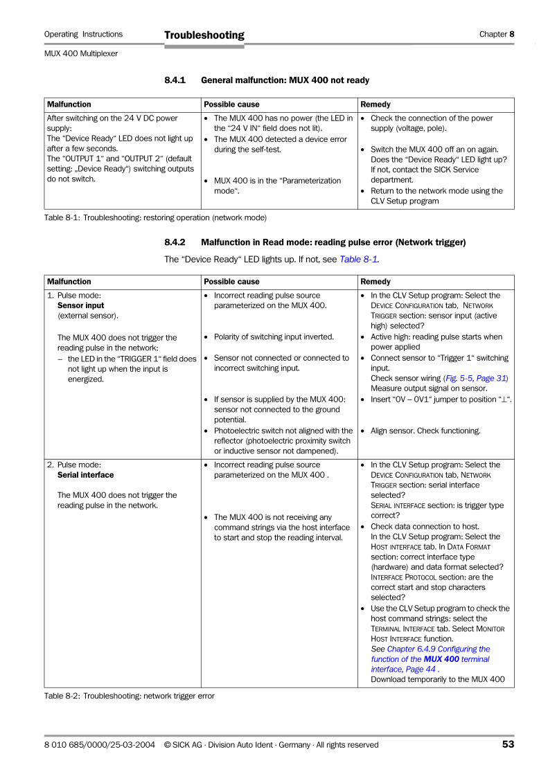
Operating Instructions Chapter 8
MUX 400 Multiplexer
Troubleshooting
8.4.1 General malfunction: MUX 400 not ready
8.4.2 Malfunction in Read mode: reading pulse error (Network trigger)
The “Device Ready“ LED lights up. If not, see Table 8-1.
Malfunction Possible cause Remedy
After switching on the 24 V DC power
supply:
The “Device Ready“ LED does not light up
after a few seconds.
The “OUTPUT 1“ and “OUTPUT 2“ (default
setting: „Device Ready“) switching outputs
do not switch.
• The MUX 400 has no power (the LED in
the “24 V IN“ field does not lit).
• The MUX 400 detected a device error
during the self-test.
• MUX 400 is in the “Parameterization
mode“.
• Check the connection of the power
supply (voltage, pole).
• Switch the MUX 400 off an on again.
Does the “Device Ready“ LED light up?
If not, contact the SICK Service
department.
• Return to the network mode using the
CLV Setup program
Table 8-1: Troubleshooting: restoring operation (network mode)
Malfunction Possible cause Remedy
1. Pulse mode:
Sensor input(external sensor).
The MUX 400 does not trigger the
reading pulse in the network:
– the LED in the “TRIGGER 1“ field does
not light up when the input is
energized.
• Incorrect reading pulse source
parameterized on the MUX 400.
• Polarity of switching input inverted.
• Sensor not connected or connected to
incorrect switching input.
• If sensor is supplied by the MUX 400:
sensor not connected to the ground
potential.
• Photoelectric switch not aligned with the
reflector (photoelectric proximity switch
or inductive sensor not dampened).
• In the CLV Setup program: Select the
DEVICE CONFIGURATION tab, NETWORK
TRIGGER section: sensor input (active
high) selected?
• Active high: reading pulse starts when
power applied
• Connect sensor to “Trigger 1“ switching
input.
Check sensor wiring (Fig. 5-5, Page 31)
Measure output signal on sensor.
• Insert “0V − 0V1“ jumper to position “⊥“.
• Align sensor. Check functioning.
2. Pulse mode:
Serial interface
The MUX 400 does not trigger the
reading pulse in the network.
• Incorrect reading pulse source
parameterized on the MUX 400 .
• The MUX 400 is not receiving any
command strings via the host interface
to start and stop the reading interval.
• In the CLV Setup program: Select the
DEVICE CONFIGURATION tab, NETWORK
TRIGGER section: serial interface
selected?
SERIAL INTERFACE section: is trigger type
correct?
• Check data connection to host.
In the CLV Setup program: Select the
HOST INTERFACE tab. In DATA FORMAT
section: correct interface type
(hardware) and data format selected?
INTERFACE PROTOCOL section: are the
correct start and stop characters
selected?
• Use the CLV Setup program to check the
host command strings: select the
TERMINAL INTERFACE tab. Select MONITOR
HOST INTERFACE function.
See Chapter 6.4.9 Configuring the function of the MUX 400 terminal interface, Page 44 .Download temporarily to the MUX 400
Table 8-2: Troubleshooting: network trigger error
8 010 685/0000/25-03-2004 © SICK AG · Division Auto Ident · Germany · All rights reserved 53
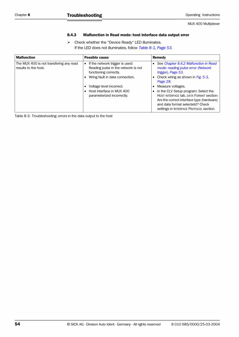
Chapter 8 Operating Instructions
MUX 400 Multiplexer
Troubleshooting
8.4.3 Malfunction in Read mode: host interface data output error
¾ Check whether the “Device Ready“ LED illuminates.
If the LED does not illuminates, follow Table 8-1, Page 53.
Malfunction Possible cause Remedy
The MUX 400 is not transfering any read
results to the host.
• If the network trigger is used:
Reading pulse in the network is not
functioning correctly.
• Wring fault in data connection.
• Voltage level incorrect.
• Host interface in MUX 400
parameterized incorrectly.
• See Chapter 8.4.2 Malfunction in Read mode: reading pulse error (Network trigger), Page 53.
• Check wiring as shown in Fig. 5-3, Page 28.
• Measure voltages.
• In the CLV Setup program: Select the
HOST INTERFACE tab, DATA FORMAT section:
Are the correct interface type (hardware)
and data format selectetd? Check
settings in INTERFACE PROTOCOL section.
Table 8-3: Troubleshooting: errors in the data output to the host
54 © SICK AG · Division Auto Ident · Germany · All rights reserved 8 010 685/0000/25-03-2004
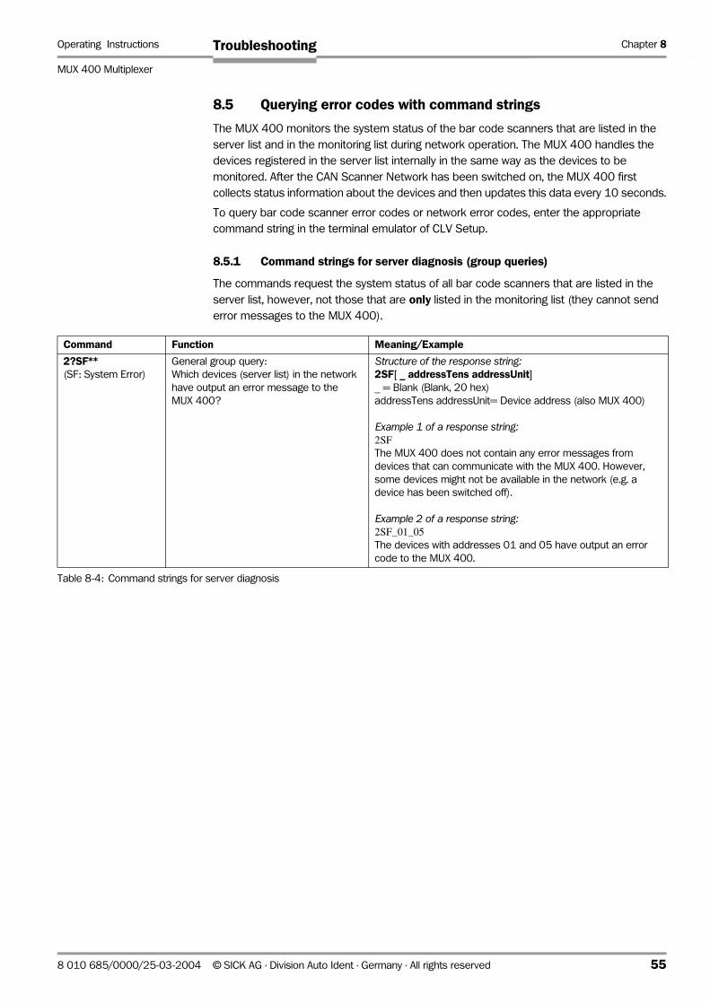
Operating Instructions Chapter 8
MUX 400 Multiplexer
Troubleshooting
8.5 Querying error codes with command strings
The MUX 400 monitors the system status of the bar code scanners that are listed in the
server list and in the monitoring list during network operation. The MUX 400 handles the
devices registered in the server list internally in the same way as the devices to be
monitored. After the CAN Scanner Network has been switched on, the MUX 400 first
collects status information about the devices and then updates this data every 10 seconds.
To query bar code scanner error codes or network error codes, enter the appropriate
command string in the terminal emulator of CLV Setup.
8.5.1 Command strings for server diagnosis (group queries)
The commands request the system status of all bar code scanners that are listed in the
server list, however, not those that are only listed in the monitoring list (they cannot send
error messages to the MUX 400).
Command Function Meaning/Example
2?SF**(SF: System Error)
General group query:
Which devices (server list) in the network
have output an error message to the
MUX 400?
Structure of the response string:2SF[ _ addressTens addressUnit]_ = Blank (Blank, 20 hex)
addressTens addressUnit= Device address (also MUX 400)
Example 1 of a response string:2SFThe MUX 400 does not contain any error messages from
devices that can communicate with the MUX 400. However,
some devices might not be available in the network (e.g. a
device has been switched off).
Example 2 of a response string:2SF_01_05The devices with addresses 01 and 05 have output an error
code to the MUX 400.
Table 8-4: Command strings for server diagnosis
8 010 685/0000/25-03-2004 © SICK AG · Division Auto Ident · Germany · All rights reserved 55
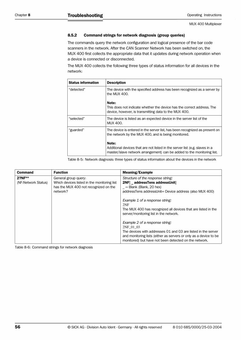
Chapter 8 Operating Instructions
MUX 400 Multiplexer
Troubleshooting
8.5.2 Command strings for network diagnosis (group queries)
The commands query the network configuration and logical presence of the bar code
scanners in the network. After the CAN Scanner Network has been switched on, the
MUX 400 first collects the appropriate data that it updates during network operation when
a device is connected or disconnected.
The MUX 400 collects the following three types of status information for all devices in the
network:
Status information Description
“detected” The device with the specified address has been recognized as a server by
the MUX 400.
Note:This does not indicate whether the device has the correct address. The
device, however, is transmitting data to the MUX 400.
“selected” The device is listed as an expected device in the server list of the
MUX 400.
“guarded” The device is entered in the server list, has been recognized as present on
the network by the MUX 400, and is being monitored.
Note:Additional devices that are not listed in the server list (e.g. slaves in a
master/slave network arrangement) can be added to the monitoring list.
Table 8-5: Network diagnosis: three types of status information about the devices in the network
Command Function Meaning/Example
2?NF**(NF:Network Status)
General group query:
Which devices listed in the monitoring list
has the MUX 400 not recognized on the
network?
Structure of the response string:2NF[ _ addressTens addressUnit]_ = Blank (Blank, 20 hex)
addressTens addressUnit= Device address (also MUX 400)
Example 1 of a response string:2NFThe MUX 400 has recognized all devices that are listed in the
server/monitoring list in the network.
Example 2 of a response string:2NF_01_03The devices with addresses 01 and 03 are listed in the server
and monitoring lists (either as servers or only as a device to be
monitored) but have not been detected on the network.
Table 8-6: Command strings for network diagnosis
56 © SICK AG · Division Auto Ident · Germany · All rights reserved 8 010 685/0000/25-03-2004
Operating Instructions Chapter 8
MUX 400 Multiplexer
Troubleshooting
8.6 SICK Support
If you cannot correct an error using the above measures, the MUX 400 may be defective.
The MUX 400 contains no user-serviceable parts .
Please contact our local SICK office or subsidary:
• The telephone numbers and email addresses are listed on the back page of this
manual.
For addresses see also www.sick.com.
¾ Do not send the device to the SICK service without first contacting us.
8 010 685/0000/25-03-2004 © SICK AG · Division Auto Ident · Germany · All rights reserved 57
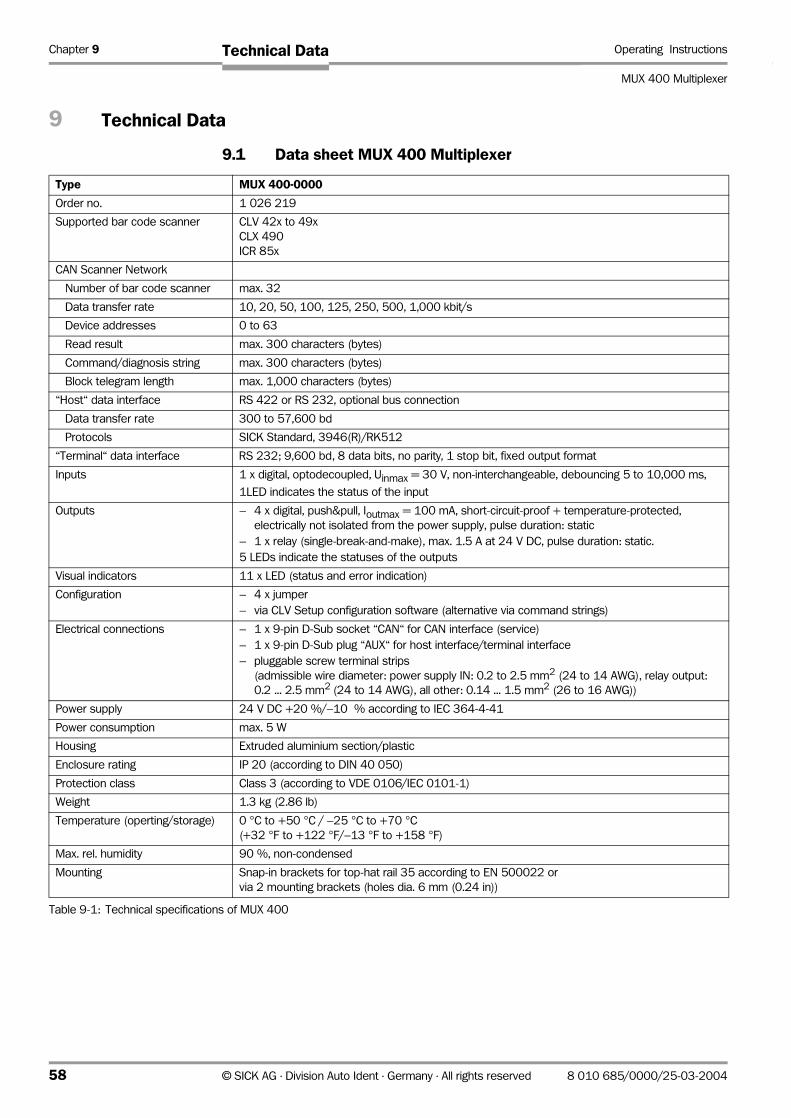
Chapter 9 Operating Instructions
MUX 400 Multiplexer
Technical Data
9 Technical Data
9.1 Data sheet MUX 400 Multiplexer
Type MUX 400-0000
Order no. 1 026 219
Supported bar code scanner CLV 42x to 49x
CLX 490
ICR 85x
CAN Scanner Network
Number of bar code scanner max. 32
Data transfer rate 10, 20, 50, 100, 125, 250, 500, 1,000 kbit/s
Device addresses 0 to 63
Read result max. 300 characters (bytes)
Command/diagnosis string max. 300 characters (bytes)
Block telegram length max. 1,000 characters (bytes)
“Host“ data interface RS 422 or RS 232, optional bus connection
Data transfer rate 300 to 57,600 bd
Protocols SICK Standard, 3946(R)/RK512
“Terminal“ data interface RS 232; 9,600 bd, 8 data bits, no parity, 1 stop bit, fixed output format
Inputs 1 x digital, optodecoupled, Uinmax = 30 V, non-interchangeable, debouncing 5 to 10,000 ms,
1LED indicates the status of the input
Outputs – 4 x digital, push&pull, Ioutmax = 100 mA, short-circuit-proof + temperature-protected,
electrically not isolated from the power supply, pulse duration: static
– 1 x relay (single-break-and-make), max. 1.5 A at 24 V DC, pulse duration: static.
5 LEDs indicate the statuses of the outputs
Visual indicators 11 x LED (status and error indication)
Configuration – 4 x jumper
– via CLV Setup configuration software (alternative via command strings)
Electrical connections – 1 x 9-pin D-Sub socket “CAN“ for CAN interface (service)
– 1 x 9-pin D-Sub plug “AUX“ for host interface/terminal interface
– pluggable screw terminal strips
(admissible wire diameter: power supply IN: 0.2 to 2.5 mm2 (24 to 14 AWG), relay output:
0.2 ... 2.5 mm2 (24 to 14 AWG), all other: 0.14 ... 1.5 mm2 (26 to 16 AWG))
Power supply 24 V DC +20 %/−10 % according to IEC 364-4-41
Power consumption max. 5 W
Housing Extruded aluminium section/plastic
Enclosure rating IP 20 (according to DIN 40 050)
Protection class Class 3 (according to VDE 0106/IEC 0101-1)
Weight 1.3 kg (2.86 lb)
Temperature (operting/storage) 0 °C to +50 °C / −25 °C to +70 °C(+32 °F to +122 °F/−13 °F to +158 °F)
Max. rel. humidity 90 %, non-condensed
Mounting Snap-in brackets for top-hat rail 35 according to EN 500022 or
via 2 mounting brackets (holes dia. 6 mm (0.24 in))
Table 9-1: Technical specifications of MUX 400
58 © SICK AG · Division Auto Ident · Germany · All rights reserved 8 010 685/0000/25-03-2004
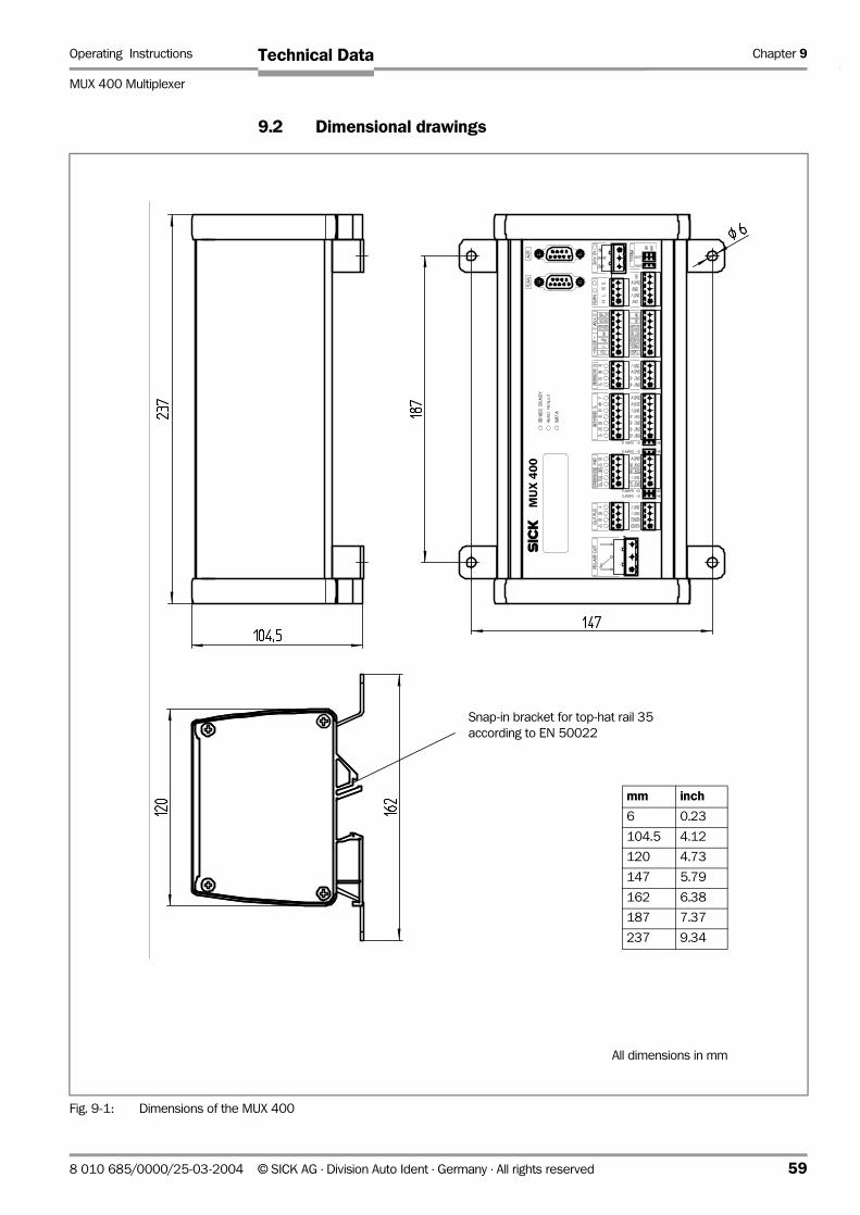
Operating Instructions Chapter 9
MUX 400 Multiplexer
Technical Data
9.2 Dimensional drawings
Fig. 9-1: Dimensions of the MUX 400
MU
X 4
00
All dimensions in mm
Snap-in bracket for top-hat rail 35
according to EN 50022
mm inch
6 0.23
104.5 4.12
120 4.73
147 5.79
162 6.38
187 7.37
237 9.34
8 010 685/0000/25-03-2004 © SICK AG · Division Auto Ident · Germany · All rights reserved 59

Chapter 10 Operating Instructions
MUX 400 Multiplexer
Appendix
10 Appendix
10.1 Overview
• Installation and operating instructions for the PC-based CLV Setup program
• Configuring the MUX 400 with command strings
• Available accessories
• Supplementary documentation
• Code table Hex – ASCII
• Copy of the EC Declaration of Conformity
• Index
60 © SICK AG · Division Auto Ident · Germany · All rights reserved 8 010 685/0000/25-03-2004
Operating Instructions Chapter 10
MUX 400 Multiplexer
Appendix
10.2 Installation and operation of the PC-based “CLV Setup“ program
The scope of delivery of the MUX 400 includes a CD-ROM (“Manuals & Software“)
containing the "CLV Setup" program.
The following is required to run the program: a PC with Windows 98TM, Windows NTTM,
Windows 2000TM or Windows XPTM, 128 MB RAM, CD-ROM drive, serial interface, mouse
(recommended).
Approximately 25 MB of hard disk space is required to install CLV Setup and CLV Assistant,
approximately 20 MB to install CLV Setup Help.
The latest software versions can be downloaded from www.sick.de.
10.2.1 Preparing for installation
1. Make sure that you have the CD-ROM (“Manuals & Software“) at hand.
2. Connect the MUX 400 to the power supply (24 V DC +20%/-10%)
(see Chapter 5.5.1 Connecting the power supply, Page 26).
3. Connect the PC to the terminal interface (port ) of the MUX 400 using a 3-core RS 232
data cable (null modem cable). See Chapter 5.5.5 Connecting the terminal interface, Page 29).
4. Switch on the power supply to the MUX 400.
The MUX 400 starts. The “Device Ready” LED lights up after the self-test has been
completed successfully. The device is in Read mode.
5. Switch on your PC and start Windows.
10.2.2 Performing installation
The CLV Setup installation program creates a directory (folder) called "CLV", a series of
subdirectories and the necessary links. Using the included uninstaller, CLV Setup can be
completely removed from the PC. As of version V2.6, CLV Setup will only be available and
further developed as a 32-bit application.
Note The following instructions describe how to install the software on Windows 98TM. These
instructions may differ depending on the operating system you are using (for example,
administrator rights are required to install the software on Windows NT4.0).
Initial installation
CLV Setup configuration software
1. Shut down all the applications running in Windows.
2. Insert the CD-ROM into the CD-ROM drive.
3. If the auto run function is enabled, the start page (table of contents) of the CD-ROM is
automatically displayed in the your browser.
4. Select the SOFTWARE folder on top left.
5. Select CLV, ICR, OPS SETUP SOFTWARE in the listing.
A table with CLV Setup information is displayed.
6. Select DOWNLOAD under SOFTWARE FILE.
7. In the FILE DOWNLOAD dialog box select the option to install directly from the CD-ROM.
Confirm with OK. The software is automatically saved in the “Programs\CLV“ directory on
your hard disk.
– or –
8 010 685/0000/25-03-2004 © SICK AG · Division Auto Ident · Germany · All rights reserved 61
Chapter 10 Operating Instructions
MUX 400 Multiplexer
Appendix
Select the option to save the software locally on your local hard disk and confirm with
OK.
In the FILE DOWNLOAD dialog box select the desired target directory on your hard disk.
The “CLVSetupxx.exe“ file is then saved at this location (xx = version number).
Select OPEN in the dialog box to start the file.
8. The installation program starts and guides you through the installation with screen
messages. The program asks you for your user name and company name. This
information appears as a header in printouts. “CLV Setup“ and CLV Assistant are
installed. The software will be entried in the Windows start menu under “Programs\CLV
Setup“.
9. Please read the Readme file, as it contains the latest information and problems
regarding CLV Setup.
10. Then confirm the final installation message by clicking “OK“.
Online CLV Setup Help
1. Return to the start page of the CD-ROM with the opened folder “Software“.
2. Select CLV, CLV HELP SOFTWARE in the listing.
A table with CLV Help information is displayed.
3. Select DOWNLOAD under SOFTWARE FILE.
4. In the FILE DOWNLOAD dialog box select the option to install directly from the CD ROM.
Confirm with OK. The software is automatically saved in the “Programs\CLV“ directory
on your hard disk.
-or-
Select the option to save the software locally on your local hard disk and confirm with
OK.
In the FILE DOWNLOAD dialog box select the same target directory as selected for
CLV Setup on your hard disk.
The “CLVHelp.exe“ file is then saved at this location.
5. After downloading the software, select OPEN in the dialog box to start the software.
The software is installed in the sub directory “Help“ of the main directory “CLV“.
CLV Help will also be entried in the Windows start menu under “Programs\CLV Setup“.
¾ Restart the PC.
Some Windows DLL files are possibly updated.
The “CLV Setup“ program, the CLV Assistant and the online “CLV Setup Help“ are installed
and ready.
The program logs all of the files that are installed to the “install.log“ file. This list is used by
the uninstaller to remove CLV Setup and must not be deleted if you want to use the
uninstaller at some time in the future.
Updating program
There are two options for installing a new version of CLV Setup:
• You can install the new version and still keep the old version (parallel installation)
– or –
• You can install the new version over the old version (overwrite)
62 © SICK AG · Division Auto Ident · Germany · All rights reserved 8 010 685/0000/25-03-2004
Operating Instructions Chapter 10
MUX 400 Multiplexer
Appendix
Installing new version and retaining old version
If you want to install the new version and still keep the old version of CLV Setup, follow the
procedure described under Initial installation. When the program asks you for the target
directory, you must specify a new directory. Both versions of the software are then available
but may not be started simultaneously.
The configuration files "*.scl" of the old version can be used in the new version and contain
the MUX 400 parameter sets. In order to do so, copy the configuration files from the "data"
directory of the old version to the "data" directory of the new version.
Installing new version over old version
When installing the new version over the old version, the files of the old version must first
be deleted (exception: the "*.scl" configuration files). They contain the parameter sets of the
MUX 400.
The uninstaller of the old version removes the program files. You can use the uninstaller to
remove all of the files (with the exception of the configuration files) or only selected files. The
default setting is a complete uninstall (the configuration files are not deleted). With the
custom uninstall, the files are listed and only selected files are uninstalled. If you choose this
uninstall method, ensure that the main directory containing the configuration files "*.scl" is
not deleted. We recommend that you move these files to a different directory and copy
them back to the "data" directory later.
1. From the Windows Start menu, choose "Programs" and the uninstaller for CLV Setup.
The uninstaller starts and guides you step by step through the uninstall procedure.
2. Select the uninstall method (complete or custom).
3. Install the new version of CLV Setup as described under Initial installation. Select the
same directory.
The new version of CLV Setup is installed. The configuration files of the old version can be
used again.
8 010 685/0000/25-03-2004 © SICK AG · Division Auto Ident · Germany · All rights reserved 63
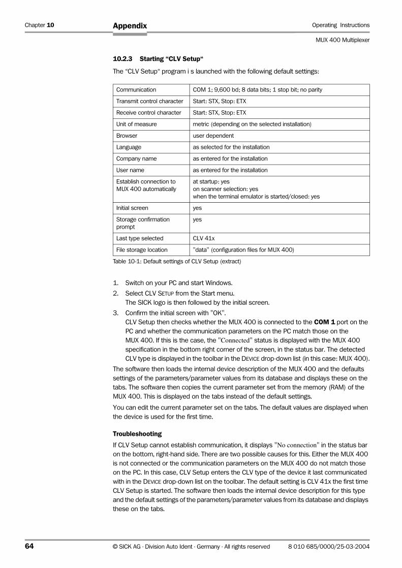
Chapter 10 Operating Instructions
MUX 400 Multiplexer
Appendix
10.2.3 Starting “CLV Setup“
The “CLV Setup“ program i s launched with the following default settings:
1. Switch on your PC and start Windows.
2. Select CLV SETUP from the Start menu.
The SICK logo is then followed by the initial screen.
3. Confirm the initial screen with "OK".
CLV Setup then checks whether the MUX 400 is connected to the COM 1 port on the
PC and whether the communication parameters on the PC match those on the
MUX 400. If this is the case, the "Connected" status is displayed with the MUX 400
specification in the bottom right corner of the screen, in the status bar. The detected
CLV type is displayed in the toolbar in the DEVICE drop-down list (in this case: MUX 400).
The software then loads the internal device description of the MUX 400 and the defaults
settings of the parameters/parameter values from its database and displays these on the
tabs. The software then copies the current parameter set from the memory (RAM) of the
MUX 400. This is displayed on the tabs instead of the default settings.
You can edit the current parameter set on the tabs. The default values are displayed when
the device is used for the first time.
Troubleshooting
If CLV Setup cannot establish communication, it displays "No connection" in the status bar
on the bottom, right-hand side. There are two possible causes for this. Either the MUX 400
is not connected or the communication parameters on the MUX 400 do not match those
on the PC. In this case, CLV Setup enters the CLV type of the device it last communicated
with in the DEVICE drop-down list on the toolbar. The default setting is CLV 41x the first time
CLV Setup is started. The software then loads the internal device description for this type
and the default settings of the parameters/parameter values from its database and displays
these on the tabs.
Communication COM 1; 9,600 bd; 8 data bits; 1 stop bit; no parity
Transmit control character Start: STX, Stop: ETX
Receive control character Start: STX, Stop: ETX
Unit of measure metric (depending on the selected installation)
Browser user dependent
Language as selected for the installation
Company name as entered for the installation
User name as entered for the installation
Establish connection to
MUX 400 automatically
at startup: yes
on scanner selection: yes
when the terminal emulator is started/closed: yes
Initial screen yes
Storage confirmation
prompt
yes
Last type selected CLV 41x
File storage location "data" (configuration files for MUX 400)
Table 10-1: Default settings of CLV Setup (extract)
64 © SICK AG · Division Auto Ident · Germany · All rights reserved 8 010 685/0000/25-03-2004
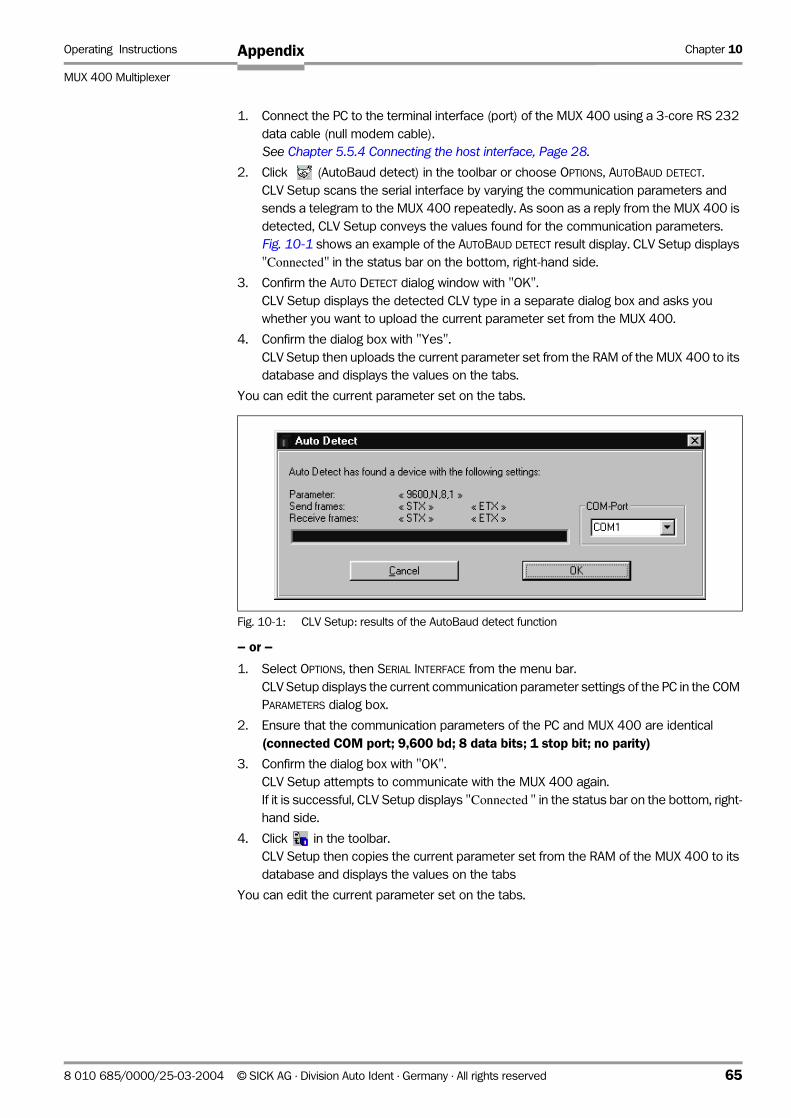
Operating Instructions Chapter 10
MUX 400 Multiplexer
Appendix
1. Connect the PC to the terminal interface (port) of the MUX 400 using a 3-core RS 232
data cable (null modem cable).
See Chapter 5.5.4 Connecting the host interface, Page 28.
2. Click (AutoBaud detect) in the toolbar or choose OPTIONS, AUTOBAUD DETECT.
CLV Setup scans the serial interface by varying the communication parameters and
sends a telegram to the MUX 400 repeatedly. As soon as a reply from the MUX 400 is
detected, CLV Setup conveys the values found for the communication parameters.
Fig. 10-1 shows an example of the AUTOBAUD DETECT result display. CLV Setup displays
"Connected" in the status bar on the bottom, right-hand side.
3. Confirm the AUTO DETECT dialog window with "OK".
CLV Setup displays the detected CLV type in a separate dialog box and asks you
whether you want to upload the current parameter set from the MUX 400.
4. Confirm the dialog box with "Yes".
CLV Setup then uploads the current parameter set from the RAM of the MUX 400 to its
database and displays the values on the tabs.
You can edit the current parameter set on the tabs.
– or –
1. Select OPTIONS, then SERIAL INTERFACE from the menu bar.
CLV Setup displays the current communication parameter settings of the PC in the COM
PARAMETERS dialog box.
2. Ensure that the communication parameters of the PC and MUX 400 are identical
(connected COM port; 9,600 bd; 8 data bits; 1 stop bit; no parity)
3. Confirm the dialog box with "OK".
CLV Setup attempts to communicate with the MUX 400 again.
If it is successful, CLV Setup displays "Connected " in the status bar on the bottom, right-
hand side.
4. Click in the toolbar.
CLV Setup then copies the current parameter set from the RAM of the MUX 400 to its
database and displays the values on the tabs
You can edit the current parameter set on the tabs.
Fig. 10-1: CLV Setup: results of the AutoBaud detect function
8 010 685/0000/25-03-2004 © SICK AG · Division Auto Ident · Germany · All rights reserved 65

Chapter 10 Operating Instructions
MUX 400 Multiplexer
Appendix
10.2.4 CLV Setup graphical user interface
The graphical user interface (GUI) of CLV Setup is largely self explanatory. The online CLV
Setup Help function provides a description of how to use the program under the menu item
HELP TO CLV-SETUP in the navigation tree. Fig. 10-2 hows the graphical user interface.
The program window of the GUI comprises the following elements:
• Title page that displays the program name, current configuration file and status
(e.g. "No File")
• Menu bar with pull-down menus
• Toolbar with buttons for triggering various functions
• Drop-down list (top right) for selecting the device type
• Left-hand frame with navigation tree for the tabs
• Right-hand frame for the tabs of the MUX 400 (Device Configuration, Host Interface
etc.). The number of tabs displayed depends on the number of tabs that have been
activated in the navigation tree on the left-hand side. The parameters on the tabs are
grouped according to their function. Some of these parameters open further dialog
boxes.
• A status bar (at the bottom of the window) with two display fields for the communication
activities between CLV Setup and the MUX 400, display of interface parameters of the
PC, error display field (system errors) of the MUX 400, device specification field and
status display for the connection to the MUX 400
Fig. 10-2: User interface of the “CLV Setup“ software
66 © SICK AG · Division Auto Ident · Germany · All rights reserved 8 010 685/0000/25-03-2004

Operating Instructions Chapter 10
MUX 400 Multiplexer
Appendix
10.2.5 Functions
The "CLV Setup" program (from V 4.0) features functions to carry out the following:
• Loading the default settings of the parameter set from the database
• Automatic communication attempt with the MUX 400 when the program is started
• Automatic software compatibility check in the MUX 400
• Uploading parameter set stored in the MUX 400
• Changing the parameters/parameter values on the tabs
• Downloading the changes to the parameter set in the MUX 400
• CLV Assistant for simplified parameterization (not for MUX 400)
• Saving the changes to the parameter set in the MUX 400 (download)
• Saving the changes to the parameter set as a configuration file "*.scl"
• Printing the configuration files
• Exporting the configuration files in RTF format
• Exporting the command strings contained in the profile bar codes in ASCII format (not
for MUX 400)
• Printing the parameter set in the form of profile bar codes (not for MUX 400)
• Direct access to the MUX 400 via a terminal emulator (select operating mode, start
operating functions, log file for communication between the MUX 400 and CLV Setup,
extended terminal mode, e.g. for displaying messages)
• AutoBaud detect for automatic communication setup with the MUX 400
• Selecting the COM port for adapting the data transfer parameters
• Monitoring the data communication of the MUX 400 host interface
• Selecting the display language
• Selecting the units of measure
• Displaying the last 10 configuration files that were processed
• Saving the CLV type that was selected last
• Automatic storage confirmation prompt when changes are made to the configuration
file
• Wizards for individual functions
• Setting switches for starting the program in the "CLVmain.ini" file
• Hot keys [F keys] for essential functions (program operation without a mouse)
• Starting program with SCL file as argument
• Macro player for recording and playing a macro file
• Context-sensitive help via the [F1] key
10.2.6 Hot keys
[F1] Start "CLV-Setup Help“ online
[F2] Open dialog box to execute device functions
[F3] Upload complete set of parameters from MUX 400
[F4] Download complete set of parameters to MUX 400
[F5] Open configuration file
[F6] Save configuration file
[F7] Load default setting of MUX 400 from CLV-Setup database
[F8] Start AutoBaud Detect
8 010 685/0000/25-03-2004 © SICK AG · Division Auto Ident · Germany · All rights reserved 67

Chapter 10 Operating Instructions
MUX 400 Multiplexer
Appendix
[F9] Load operating data from MUX 400 to be displayed/text to be entered
[F10] Open Terminal Emulator
10.2.7 Opening and closing tabs
After the program has started, CLV Setup shows those tabs in the right-hand frame whose
name is surrounded by a frame in the navigation tree. The first tab covers the subsequent
tabs. The tab titles are still visible. When you click the buttons in the tabs, further sub-dialogs
are displayed (also in the form of tabs). All the tabs then move to the right. You can scroll
through the tabs with the scrollbars in the top right-hand corner of the frame.
The tabs can be opened or closed in the following way:
By using the navigation tree:
• Open:
Double-click or place the cursor on the entry and select “show dialog” in the menu with
the secondary mouse button.
To display further entries under a branch, click the "+" symbol.
To hide a branch, click "-".
• Close:
Place the cursor on the entry and select “close dialog” in the menu with the secondary
mouse button.
In the frame:
• Open:
Click the desired tab or scroll the tab display.
• Close:
Click the red cross in the top left-hand square to close the tab displayed in the
foreground.
10.2.8 Online help – CLV Setup
The online help program "CLV Setup Help" assists you in operating the "CLV Setup"
program. The help program runs in an HTML browser (e.g. "Microsoft Internet ExplorerTM").
You can call up context-sensitive help on each parameter as well as a description of its
function.
1. Press the [F1] key.
The browser is launched automatically and displays the help topic.
2. If the program cannot find a browser, CLV Setup asks you to specify the storage location
on the hard disk.
Enter the name of the executable file and the path in the dialog box.
3. Use the [Alt]+ [Tab] keys to switch between the CLV Setup and CLV Setup Help
applications and prevent several browser windows from being opened.
4. To display an overview of the help function, select HELP, CONTENTS from the CLV Setup
menu bar.
5. In the left frame click on the desired entry in the navigation tree.
CLV Setup Help then displays the associated help text in the right-hand frame and
jumps to the parameter heading.
10.2.9 Transferring parameter sets between CLV-Setup and MUX 400
See Chapter 6.4 Configuration (parameterizing), Page 35.
68 © SICK AG · Division Auto Ident · Germany · All rights reserved 8 010 685/0000/25-03-2004
Operating Instructions Chapter 10
MUX 400 Multiplexer
Appendix
10.2.10 Dealing with unkown parameters
Uploading from the MUX 400
If the CLV Setup program does not recognize parameters or parameter values of the
MUX 400 transferred during the upload, it outputs a warning message. Unknown
parameters/parameter values can result from the following, for example: The MUX 400 is a
special device or the version of CLV Setup is older than the software of the MUX 400. CLV
Setup displays the unknown parameters in the window on the EXTRAS tab. The parameters
are displayed in the form of command strings and can be edited using the command string
conventions. In this way, upward compatibility with the MUX 400 is ensured. When the
parameter set is saved as a configuration file in CLV Setup, these parameters/parameter
values are also taken into account as with a download to the MUX 400.
Downloading to the MUX 400
If the MUX 400 does not accept individual parameters or parameter values in the
parameter set downloaded with CLV Setup, it outputs a separate warning for each
parameter in CLV Setup. This is due to the fact that one of the CLV Setup software versions
is newer than the software in the MUX 400, and it contains new parameters/parameter
values arising from the continued development of this CLV type. The affected MUX 400
contains an older software version which does not recognize these parameters/parameter
values, however.
We recommend that you check the effects of warnings in the MUX 400 as follows:
1. Check whether the MUX 400 functions correctly after the parameter set is downloaded.
2. Click in the toolbar.
CLV Setup loads the default settings from the database.
3. Click in the toolbar.
CLV Setup copies the problem parameter set from the MUX 400 (upload).
4. Click in the toolbar.
CLV Setup prints out the problem parameter set when you confirm the dialog box.
5. Open the previous configuration file "*.scl" for the MUX 400.
6. Click in the toolbar.
CLV Setup prints out the previous parameter set when you confirm the dialog box.
7. Compare the two parameter sets.
To restore the previous status, correct individual parameters in the problem parameter
set if necessary and download them to the MUX 400 again.
Opening configuration files "*.scl"
Every time it loads configuration files, CLV Setup checks whether it recognizes all the
parameters/values of the MUX 400.
If CLV Setup detects an error, it outputs a warning and enters the problem parameter/
parameter value in the window of the EXTRAS tab.
10.2.11 Writing a log file in terminal emulator
The terminal emulator can log the communication between CLV Setup and the MUX 400.
CLV Setup stores the data transmitted in both directions with the following identifiers:
MUX 400 -->: MUX 400 sending to CLV Setup
--> MUX 400: MUX 400 receiving from CLV Setup
8 010 685/0000/25-03-2004 © SICK AG · Division Auto Ident · Germany · All rights reserved 69

Chapter 10 Operating Instructions
MUX 400 Multiplexer
Appendix
1. Click in the toolbar.
The TERMINAL EMULATOR window is then displayed
2. On the right, activate the empty checkbox in front of the WRITE LOGFILE radio button.
The SAVE LOG FILE AS... dialog box is then displayed.
3. Enter a file name with the extension ".log" and exit the window with SAVE.
CLV Setup saves the file in the "data" subdirectory and records communication in the
log file.
4. To terminate logging, deactivate the checkbox in front of the WRITE LOGFILE radio button
or close the terminal emulator.
10.2.12 Starting CLV Setup with an INI file as argument
When the program is started, CLV Setup can also be transferred the name of an INI file as
a parameter. To do so, enter "/INI" in front of the file.
Example:
"CLVmain32.exe\data\Set 1_MUX 400.scl /INI user.ini"
CLV Setup is launched with the initialization data contained in the "user.ini" file and loads the
configuration file "Set1_MUX 400.scl" from the "data" subdirectory straight away.
The "user.ini" file must be stored in the same directory as "CLVmain32.exe".
You can use this method to link CLV Setup to several different configurations on your
Windows desktop.
In this way, for example, you can prevent CLV Setup from attempting to establish a
connection when a MUX 400 is not connected.
10.2.13 CLV Assistant
The CLV Assistant is not available for the MUX 400.
70 © SICK AG · Division Auto Ident · Germany · All rights reserved 8 010 685/0000/25-03-2004

Operating Instructions Chapter 10
MUX 400 Multiplexer
Appendix
10.3 Configuring the MUX 400 with command strings
The MUX 400 can be parameterized and operated via the terminal interface and the host
interface. Parameters that are not recognized by CLV Setup can also be used by following
the conventions for command strings. This enables special devices, for example, to be
parameterized and new MUX 400 parameters to be configured which may not be
recognized by the CLV Setup program if this is older than the software on the MUX 400. The
CLV Setup user interface is based on the command language.
The command language accesses the MUX 400 command interpreter directly. It must be
used carefully. The commands sent to the MUX 400 are executed immediately.
Parameter values that have been changed by commands are initially only active in the
current parameter set in the RAM of the MUX 400. Using a special command, the modified
parameter set must also be copied to the EEPROM so that it is stored permanently.
Otherwise, the changes will be lost when the power supply is switched off.
The ONLINE MODE of the terminal emulator in CLV Setup enables the MUX 400 to be
parameterized directly with command strings. Fig. 10-3 contains the initial screen of the
terminal emulator with the command field and output window which shows how the PC and
MUX 400 communicate with each other.
1. Click in the toolbar.
The TERMINAL EMULATOR window is then displayed. The MUX 400 is in Read mode.
2. Click PARAMETERIZE under DEVICE MODE.
The MUX 400 cancels Read mode. The "Device Ready" LED is extinguished.
CLV Setup switches the MUX 400 to the PARAMETER mode by issuing an appropriate
command.
In the Parameter mode, all commands begin with the number "3".
3. Enter the desired command in the command field ➀ and press the [Return] key.
The command is then sent to the MUX 400.
With a few exceptions, the MUX 400 replies to a command with correct syntax with an
echo.
Fig. 10-3: CLV Setup: entering commands in the terminal emulator
➁
➀
8 010 685/0000/25-03-2004 © SICK AG · Division Auto Ident · Germany · All rights reserved 71
Chapter 10 Operating Instructions
MUX 400 Multiplexer
Appendix
Example: Entering "3?LT" causes the MUX 400 to output the parameter values of the reading
pulse in encoded form in the output window ➁.
4. Activate the READ MODE radio button to return to the Read mode.
The "Device Ready" LED lights up
Note Changes that are made directly to parameter values in the MUX 400 using command strings
are only registered and displayed in CLV Setup after the current parameter set has been
uploaded from the MUX 400.
A list of command strings is available on request.
Outputting command strings for all the parameter settings
You can output a list of all the parameter settings configured with CLV Setup in ASCII format.
To do so, proceed as follows:
1. In the menu bar, choose EXPORT PARAMETERS under MUX 400.
Starting from the default settings, CLV Setup collects all the command strings required
to parameterize the default configuration and customized settings.
The SELECT FILE NAME FOR PARAMETER EXPORT dialog box is displayed.
2. Enter a file name and click the SAVE button.
CLV Setup saves the data as a text file in the directory shown.
You can open this text file using any Windows text editor.
If the commands are sent from the host/PLC to the MUX 400 for configuration, note that
"3 EEW" has to be sent as the last command to ensure that they are permanently
transferred to the MUX 400 (EEProm).
10.4 Replacing a MUX 400 (copying the parameter set)
If you need to replace the MUX 400 and transfer the current parameter set to the
replacement device, you can download it with CLV Setup..
The parameter set can only be transferred between identical device types (e. g. from one
MUX 400 to another MUX 400, etc.).
To download the parameter set, you must connect a PC running the CLV Setup software to
the replacement device. The parameter set of the MUX 400 that is to be replaced must be
available as a configuration file in CLV Setup, otherwise the device must be configured from
scratch.
1. Switch off the power supply of the MUX 400.
2. Remove all cables from the MUX 400.
3. Remove the MUX 400 from the bracket.
4. Install and connect the replacement device.
5. Connect the PC to the terminal interface of the MUX 400 using a 3-core RS 232 data
cable (null modem cable).
(see Chapter 5.5.5 Connecting the terminal interface, Page 29).
6. Switch on the power supply to the MUX 400.
The MUX 400 starts. The “Device Ready” LED lights up after the self-test has been
completed successfully. The device is in read mode.
7. Switch on your PC and start Windows.
72 © SICK AG · Division Auto Ident · Germany · All rights reserved 8 010 685/0000/25-03-2004
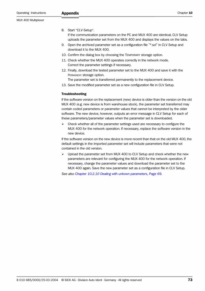
Operating Instructions Chapter 10
MUX 400 Multiplexer
Appendix
8. Start “CLV-Setup“.
If the communication parameters on the PC and MUX 400 are identical, CLV Setup
uploads the parameter set from the MUX 400 and displays the values on the tabs.
9. Open the archived parameter set as a configuration file "*.scl" in CLV Setup and
download it to the MUX 400.
10. Confirm the dialog box by choosing the TEMPORARY storage option.
11. Check whether the MUX 400 operates correctly in the network mode.
Correct the parameter settings if necessary.
12. Finally, download the tested parameter set to the MUX 400 and save it with the
PERMANENT storage option.
The parameter set is transferred permanently to the replacement device.
13. Save the modified parameter set as a new configuration file in CLV Setup.
Troubleshooting
If the software version on the replacement (new) device is older than the version on the old
MUX 400 (e.g. new device is from warehouse stock), the parameter set transferred may
contain coded parameters or parameter values that cannot be interpreted by the older
software. The new device, however, outputs an error message in CLV Setup for each of
these parameters/parameter values when the parameter set is downloaded.
¾ Check whether all of the parameter settings used are necessary to configure the
MUX 400 for the network operation. If necessary, replace the software version in the
new device.
If the software version on the new device is more recent than that on the old MUX 400, the
default settings in the imported parameter set will include parameters that were not
contained in the old version.
¾ Upload the parameter set from MUX 400 to CLV Setup and check whether the new
parameters are relevant for configuring the MUX 400 for the network operation. If
necessary, change the parameter values and download the parameter set to the
MUX 400 again. Save the new parameter set as a configuration file in CLV Setup.
See also Chapter 10.2.10 Dealing with unkown parameters, Page 69.
8 010 685/0000/25-03-2004 © SICK AG · Division Auto Ident · Germany · All rights reserved 73
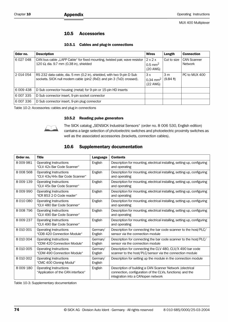
Chapter 10 Operating Instructions
MUX 400 Multiplexer
Appendix
10.5 Accessories
10.5.1 Cables and plug-in connections
10.5.2 Reading pulse generators
The SICK catalog „SENSICK Industrial Sensors“ (order no. 8 006 530, English edition)
cantains a large selection of photoelectric switches and photoelectric proximity switches as
well as the associated accessories (brackets, connection cables).
10.6 Supplementary documentation
Oder no. Description Wires Length Connection
6 027 048 CAN bus cable „LAPP Cable“ for fixed mounting, twisted pair, wave resistor
120 Ω, dia. 9.7 mm (0.38 in), shielded
2 x 2 x
0.5 mm2
(20 AWG)
Cut to size CAN Scanner
Network
2 014 054 RS 232 data cable, dia. 5 mm (0.2 in), shielded, with two 9-pin D Sub
sockets. SICK null modem cable (pin2 (RxD) and pin 3 (TxD) crossed).
3 x
0.34 mm2
(22 AWG)
3 m
(9.84 ft)
PC to MUX 400
6 009 438 D Sub connector housing (metal) for 9-pin or 15-pin HD inserts
6 007 335 D Sub connector insert, 9-pin socket connector
6 007 336 D Sub connector insert, 9-pin plug connector
Table 10-2: Accessories: cables and plug-in connections
Order no. Title Language Contents
8 009 981 Operating Instructions
“CLV 42x Bar Code Scanner“
English Description for mounting, electrical installing, setting-up, configuring
and operating
8 008 568 Operating Instructions
“CLV 43x/44x Bar Code Scanner“
English Description for mounting, electrical installing, setting-up, configuring
and operating
8 009 139 Operating Instructions
“CLV 45x Bar Code Scanner“
English Description for mounting, electrical installing, setting-up, configuring
and operating
8 009 990 Operating Instructions
“ICR 853 2-D Code reader“
English Description for mounting, electrical installing, setting-up, configuring
and operating
8 010 080 Operating Instructions
“CLV 480 Bar Code Scanner“
English Description for mounting, electrical installing, setting-up, configuring
and operating
8 008 796 Operating Instructions
“CLV 490 Bar Code Scanner“
English Description for mounting, electrical installing, setting-up, configuring
and operating
8 009 237 Operating Instructions
“CLX 490 Bar Code Scanner“
English Description for mounting, electrical installing, setting-up, configuring
and operating
8 010 001 Operating Instructions
“CDB 420 Connection Module“
German/
English
Description for connecting the bar code scanner to the host/PLC/
sensor via the connection module
8 010 004 Operating Instructions
“CDM 420 Connection Module“
German/
English
Description for connecting the bar code scanner to the host/PLC/
sensor via the connection module
8 010 005 Operating Instructions
“CDM 490 Connection Module“
German/
English
Description for connecting the CLV 480, CLV/X 490 bar code
scanner to the host/PLC/sensor via the connection module
8 010 002 Operating Instructions
“CMC 400 Cloning-Modul“
German/
English
Description for setting up the module in the connection module
8 009 180 Operating Instructions
“Application of the CAN interface“
English Description of building a CAN Scanner Network (electrical
connection, configuration of the CLVs, functions) and the
integration into a CANopen network
Table 10-3: Supplementary documentation
74 © SICK AG · Division Auto Ident · Germany · All rights reserved 8 010 685/0000/25-03-2004
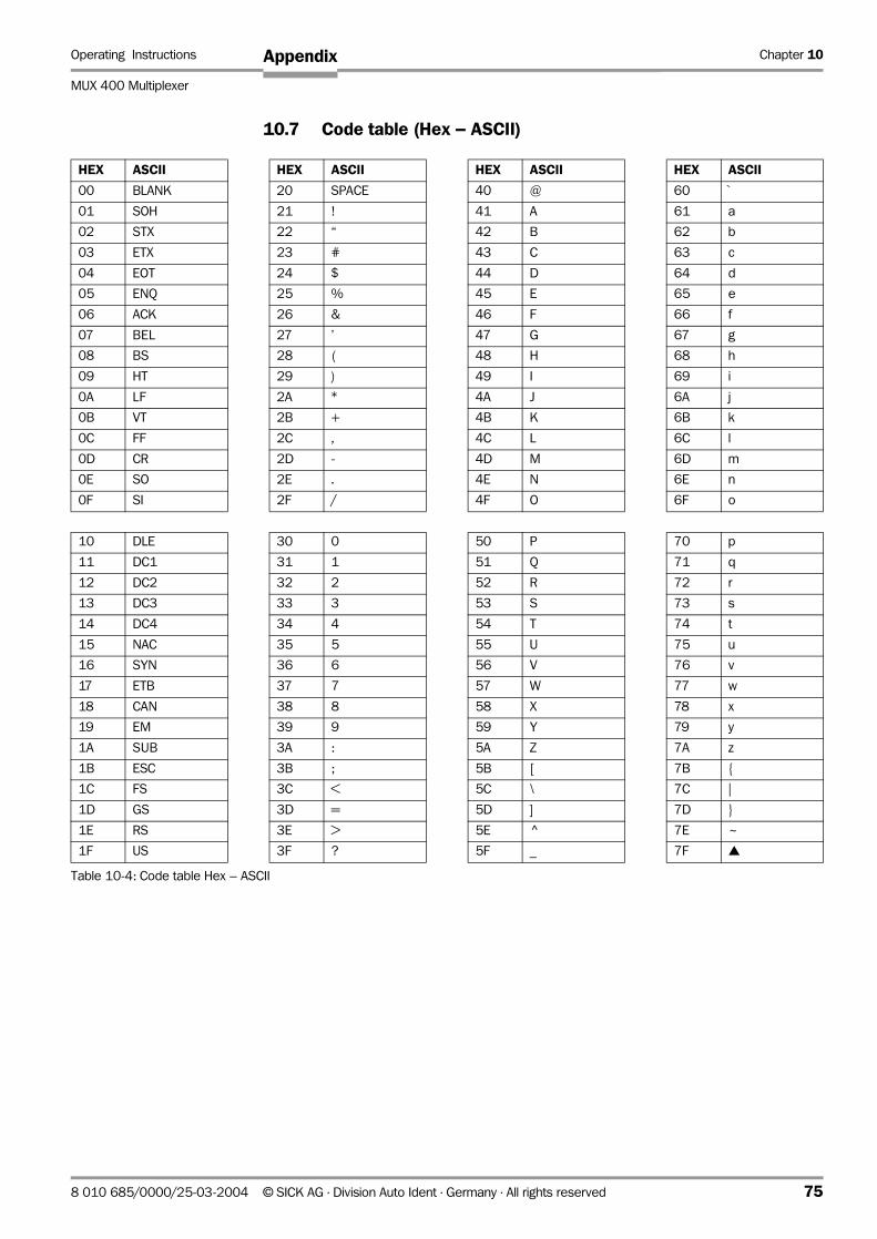
Operating Instructions Chapter 10
MUX 400 Multiplexer
Appendix
10.7 Code table (Hex – ASCII)
HEX ASCII HEX ASCII HEX ASCII HEX ASCII
00 BLANK 20 SPACE 40 @ 60 `
01 SOH 21 ! 41 A 61 a
02 STX 22 “ 42 B 62 b
03 ETX 23 # 43 C 63 c
04 EOT 24 $ 44 D 64 d
05 ENQ 25 % 45 E 65 e
06 ACK 26 & 46 F 66 f
07 BEL 27 ’ 47 G 67 g
08 BS 28 ( 48 H 68 h
09 HT 29 ) 49 I 69 i
0A LF 2A * 4A J 6A j
0B VT 2B + 4B K 6B k
0C FF 2C , 4C L 6C l
0D CR 2D - 4D M 6D m
0E SO 2E . 4E N 6E n
0F SI 2F / 4F O 6F o
10 DLE 30 0 50 P 70 p
11 DC1 31 1 51 Q 71 q
12 DC2 32 2 52 R 72 r
13 DC3 33 3 53 S 73 s
14 DC4 34 4 54 T 74 t
15 NAC 35 5 55 U 75 u
16 SYN 36 6 56 V 76 v
17 ETB 37 7 57 W 77 w
18 CAN 38 8 58 X 78 x
19 EM 39 9 59 Y 79 y
1A SUB 3A : 5A Z 7A z
1B ESC 3B ; 5B [ 7B
1C FS 3C < 5C \ 7C |
1D GS 3D = 5D ] 7D
1E RS 3E > 5E ^ 7E ~
1F US 3F ? 5F _ 7F
Table 10-4: Code table Hex – ASCII
8 010 685/0000/25-03-2004 © SICK AG · Division Auto Ident · Germany · All rights reserved 75
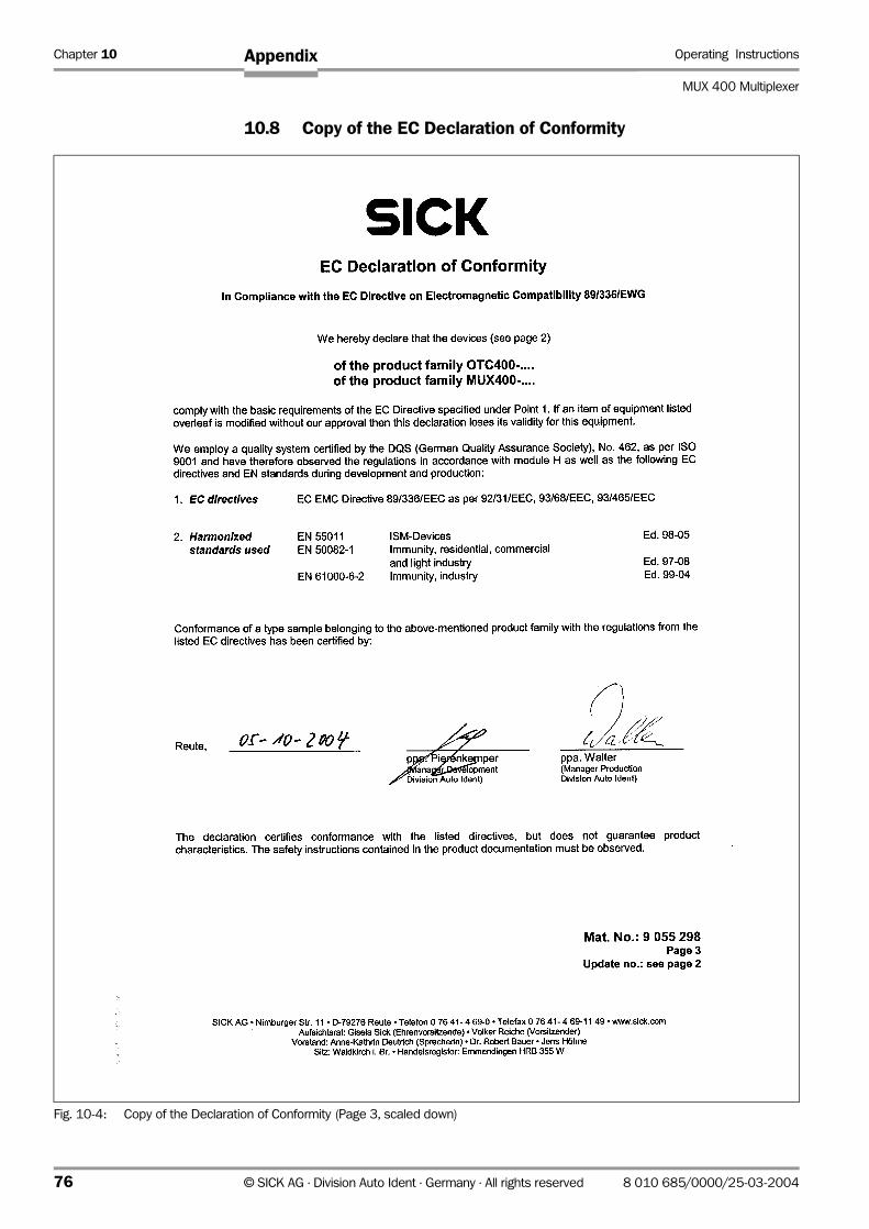
Chapter 10 Operating Instructions
MUX 400 Multiplexer
Appendix
10.8 Copy of the EC Declaration of Conformity
Fig. 10-4: Copy of the Declaration of Conformity (Page 3, scaled down)
76 © SICK AG · Division Auto Ident · Germany · All rights reserved 8 010 685/0000/25-03-2004

Operating Instructions Chapter 10
MUX 400 Multiplexer
Appendix
Fig. 10-5: Copy of the Declaration of Conformity (Page 2, scaled down)
8 010 685/0000/25-03-2004 © SICK AG · Division Auto Ident · Germany · All rights reserved 77
Chapter 10 Operating Instructions
MUX 400 Multiplexer
Appendix
10.9 Index
AAbbreviations ......................................................................................6
BBrowser ..............................................................................................13
CCAN interface
- Connecting .................................................................................26
- Maximum cable lengths ........................................................24
- Parameterizing ..........................................................................40
- Required wire diameters.......................................................25
CD ROM..............................................................................................13
CLV Setup
- Dealing with unkown parameters......................................69
- Default settings ........................................................................64
- Download....................................................................................36
- Functions (overview) ..............................................................67
- Hot keys ......................................................................................67
- Ini file ............................................................................................70
- Log file serial communication .............................................69
- Start ..............................................................................................64
- tabs (overview) .........................................................................38
- Upload..........................................................................................36
- User interface............................................................................66
CLV Setup Help ...............................................................................68
Command strings
- Entry in terminal emulator ....................................................71
- Function.......................................................................................71
- Outputting in a file....................................................................72
Configuration (parameterizing) ..................................................35
Connecting the PC..........................................................................29
Connection diagram ......................................................................27
Connector pin and terminal strips assignment ...................23
DDeclaration of conformity ............................................................76
Default settings
- CLV Setup...................................................................................64
- MUX 400 print out...................................................................35
- Restore in the MUX 400.......................................................34
Device number................................................................................16
Dimensional drawings...................................................................59
Displaying operating data............................................................49
Disposal .............................................................................................51
Documentation (supplementary) .............................................74
Download
- Execution ....................................................................................36
- Function.......................................................................................36
EElectrical installation ......................................................................22
Enclosure rating ..............................................................................58
Error messages
- Displaying in the Terminal Emulator .................................49
- Function.......................................................................................50
- Querying with command strings.........................................55
FFirmware ...............................................................................................2
HHost interface
- Connecting................................................................................. 28
- Default setting .......................................................................... 29
- Function ...................................................................................... 16
- Hardware selection................................................................. 29
- Maximum cable lengths........................................................ 25
- Monitoring via the Terminal Emulator.............................. 47
- Parameterizing.......................................................................... 41
IIndicators........................................................................................... 20
Installation
- Electrical installation............................................................... 22
- Mounting..................................................................................... 21
LLEDs
- Function ...................................................................................... 20
- Position........................................................................................ 20
MMaintenance .................................................................................... 51
Malfunctions
- Analysis and troubleshooting.............................................. 52
- Error messages........................................................................ 50
Messages (terminal interface).................................................. 49
Method of operation of the Mux 400 .................................... 16
Monitoring host interface
- Activate ....................................................................................... 48
- Function ...................................................................................... 47
Mounting bracket ........................................................................... 59
Mux Data Timing
- Activate ....................................................................................... 47
- Function ...................................................................................... 47
Mux Diagnosis
- Activate ....................................................................................... 44
- Function ...................................................................................... 44
NNetwork trigger
- Function ...................................................................................... 16
- Parameterizing.......................................................................... 43
OOnline help........................................................................................ 68
Operating modes ........................................................................... 35
Operation
- Function of the LED indicators ........................................... 20
- with CLV Setup ......................................................................... 36
- with command strings ........................................................... 71
PParameter set
- Download ................................................................................... 36
- Function ...................................................................................... 36
- Upload ......................................................................................... 36
78 © SICK AG · Division Auto Ident · Germany · All rights reserved 8 010 685/0000/25-03-2004

Operating Instructions Chapter 10
MUX 400 Multiplexer
Appendix
Parameterizing
- Function ...................................................................................... 35
- Guide............................................................................................ 39
- Replacing a MUX 400 ........................................................... 72
- with CLV Setup ......................................................................... 36
- with command strings ........................................................... 71
Power consumption ...................................................................... 12
Power supply
- Connection................................................................................. 26
- Requirements ........................................................................... 26
Product features............................................................................. 14
Protection class .............................................................................. 58
RReading pulse
- Troubleshooting ....................................................................... 53
Reading pulse sensor
- Connection at switching input............................................. 30
- Parameterize pulse source.................................................. 43
Reading result
- Troubleshooting ....................................................................... 54
Relay output
- Characteristic data.................................................................. 33
- Circuit diagram ......................................................................... 33
- Parameterizing.......................................................................... 44
Removing the device
- Disposal ...................................................................................... 51
- Procedure................................................................................... 21
Repair ................................................................................................. 57
Replacing a MUX 400 .................................................................. 72
SSafety
- Authorized personnel............................................................. 11
- Enclosure rating/protection class ..................................... 58
- Features...................................................................................... 14
- Intended use............................................................................. 11
- Notes on device ...................................................................... 13
- Power supply............................................................................. 26
Scope of delivery ........................................................................... 13
Self-test.............................................................................................. 52
Separator .......................................................................................... 42
Server Diagnosis
- Activate ....................................................................................... 46
- Function ...................................................................................... 46
SICK Homepage................................................................................9
SICK Support ................................................................................... 57
Software versions .............................................................................2
Switching input TRIGGER 1
- Characteristic data.................................................................. 31
- Connecting................................................................................. 30
- Function ...................................................................................... 16
- Parameterizing.......................................................................... 43
Switching off the MUX 400 ........................................................ 50
Switching outputs OUTPUT 1 to 4
- Characteristic data.................................................................. 32
- Function ...................................................................................... 16
- Parameterizing.......................................................................... 44
- Wiring ........................................................................................... 32
System messages
- Displaying in the Terminal Emulator .................................49
- Function.......................................................................................49
System requirements
- For CAN Scanner Network ...................................................14
- For MUX 400.............................................................................13
TTable of figures...................................................................................7
Table of tables....................................................................................6
Technical data..................................................................................58
Terminal Emulator ..........................................................................45
Terminal interface
- Connecting .................................................................................29
- Data format................................................................................64
- Default setting...........................................................................34
- Function.......................................................................................16
- Maximum cable length ..........................................................29
- Operating modes .....................................................................19
- Parameterizing ..........................................................................44
Troubleshooting
- Error messages ........................................................................50
- Troubleshooting........................................................................52
UUpload
- Execution ....................................................................................36
- Function.......................................................................................36
Use of the MUX 400 .....................................................................11
User interface...................................................................................66
VView of the device..........................................................................15
WWarranty.............................................................................................12
Windows.............................................................................................13
8 010 685/0000/25-03-2004 © SICK AG · Division Auto Ident · Germany · All rights reserved 79
SICK AG | Waldkirch/Reute | Germany | www.sick.com
AustraliaPhone +61 3 9497 4100 1800 33 48 02 – tollfreeE-Mail [email protected]
Belgium/LuxembourgPhone +32 (0)2 466 55 66E-Mail [email protected]
BrasilPhone +55 11 5091-4900E-Mail [email protected]
Ceská RepublikaPhone +420 2 57 91 18 50E-Mail [email protected]
ChinaPhone +852-2763 6966E-Mail [email protected]
DanmarkPhone +45 45 82 64 00E-Mail [email protected]
DeutschlandPhone +49 (0)2 11 53 01-270E-Mail [email protected]
EspañaPhone +34 93 480 31 00E-Mail [email protected]
FrancePhone +33 1 64 62 35 00E-Mail [email protected]
Great BritainPhone +44 (0)1727 831121E-Mail [email protected]
IndiaPhone +91–22–2822 7084E-Mail [email protected]
ItaliaPhone +39 02 27 40 93 19E-Mail [email protected]
JapanPhone +81 (0)3 3358 1341E-Mail [email protected]
NederlandsPhone +31 (0)30 229 25 44E-Mail [email protected]
Norge Phone +47 67 81 50 00E-Mail [email protected]
ÖsterreichPhone +43 (0)22 36 62 28 8-0E-Mail [email protected]
PolskaPhone +48 22 837 40 50E-Mail [email protected]
Republic of KoreaPhone +82-2 786 6321/4E-Mail [email protected]
Republika SlowenijaPhone +386 (0)1-47 69 990E-Mail [email protected]
RussiaPhone +7 95 775 05 30E-Mail [email protected]
SchweizPhone +41 41 619 29 39E-Mail [email protected]
SingaporePhone +65 6744 3732E-Mail [email protected]
SuomiPhone +358-9-25 15 800E-Mail [email protected]
SverigePhone +46 8 680 64 50E-Mail [email protected]
TaiwanPhone +886 2 2365-6292E-Mail [email protected]
TürkiyePhone +90 216 388 95 90 pbxE-Mail [email protected]
USA/Canada/MéxicoPhone +1(952) 941-6780 1 800-325-7425 – tollfreeE-Mail [email protected]
More representatives and agencies in all major industrial nations at www.sick.com
8010
685/
25-0
3-20
04 •
5M
/TR<
PM6.
5/FM
7.0/
PDF>
/VD
. P
rinte
d in
Ger
man
y .
Subj
ect t
o ch
ange
with
out n
otic
e .
The
spec
ified
pro
duct
feat
ures
and
tech
nica
l dat
a do
not
repr
esen
t any
gua
rant
ee .
05
Aft i
nt55


