56
MVI46-LNG SLC Platform Landis & Gyr Telegyr Interface Module User Manual September 12, 2006
MVI46-LNG SLC Platform
Landis & Gyr Telegyr Interface Module
User Manual
September 12, 2006

Please Read This Notice Successful application of this module requires a reasonable working knowledge of the Rockwell Automation SLC hardware, the MVI46-LNG Module and the application in which the combination is to be used. For this reason, it is important that those responsible for implementation satisfy themselves that the combination will meet the needs of the application without exposing personnel or equipment to unsafe or inappropriate working conditions.
This manual is provided to assist the user. Every attempt has been made to assure that the information provided is accurate and a true reflection of the product's installation requirements. In order to assure a complete understanding of the operation of the product, the user should read all applicable Rockwell Automation documentation on the operation of the Rockwell Automation hardware.
Under no conditions will ProSoft Technology, Inc. be responsible or liable for indirect or consequential damages resulting from the use or application of the product.
Reproduction of the contents of this manual, in whole or in part, without written permission from ProSoft Technology, Inc. is prohibited.
Information in this manual is subject to change without notice and does not represent a commitment on the part of ProSoft Technology, Inc. Improvements and/or changes in this manual or the product may be made at any time. These changes will be made periodically to correct technical inaccuracies or typographical errors.
Your Feedback Please
We always want you to feel that you made the right decision to use our products. If you have suggestions, comments, compliments or complaints about the product, documentation or support, please write or call us.
ProSoft Technology, Inc. 1675 Chester Avenue, Fourth Floor Bakersfield, CA 93301 (661) 716-5100 (661) 716-5101 (Fax) http://www.prosoft-technology.com
Copyright © ProSoft Technology, Inc. 2000 - 2006. All Rights Reserved.
MVI46-LNG User Manual September 12, 2006

Contents MVI46-LNG ♦ SLC Platform Landis & Gyr Telegyr Interface Module
ProSoft Technology, Inc. Page 3 of 56 September 12, 2006
Contents
PLEASE READ THIS NOTICE...........................................................................................................2 Your Feedback Please ..................................................................................................................2
1 PRODUCT SPECIFICATIONS....................................................................................................5 1.1 General Specifications..................................................................................................5
1.1.1 Physical..........................................................................................................................6 1.1.2 SLC Interface .................................................................................................................7
1.2 Hardware Specifications...............................................................................................7
2 FUNCTIONAL OVERVIEW .........................................................................................................9 2.1 General Concepts..........................................................................................................9
2.1.1 Module Power Up ..........................................................................................................9 2.1.2 Main Logic Loop...........................................................................................................10 2.1.3 Backplane Data Transfer .............................................................................................10 2.1.4 Normal Data Transfer ..................................................................................................12
3 INSTALLING AND CONFIGURING THE MODULE.................................................................17 3.1 Module Data .................................................................................................................19
3.1.1 MVI46-LNG Database Map..........................................................................................19
4 LADDER LOGIC........................................................................................................................21 4.1 MainRoutine .................................................................................................................21 4.2 Transfer Routine..........................................................................................................23 4.3 CMDS ............................................................................................................................25
5 DIAGNOSTICS AND TROUBLESHOOTING ...........................................................................29 5.1 Reading Status Data From the Module .....................................................................29
5.1.1 The Configuration/Debug Menu...................................................................................29 5.1.2 Required Hardware......................................................................................................30 5.1.3 Required Software .......................................................................................................31

MVI46-LNG ♦ SLC Platform Contents Landis & Gyr Telegyr Interface Module
Page 4 of 56 ProSoft Technology, Inc. September 12, 2006
5.1.4 Using the Configuration/Debug Port............................................................................ 31 5.1.5 Main Menu................................................................................................................... 32
5.2 LED Status Indicators................................................................................................. 37 5.2.1 Clearing a Fault Condition........................................................................................... 38 5.2.2 Troubleshooting........................................................................................................... 38
6 REFERENCE ............................................................................................................................ 41 6.1 Cable Connections...................................................................................................... 41
6.1.1 RS-232 ........................................................................................................................ 41 6.1.2 RS-232 Configuration/Debug Port............................................................................... 43 6.1.3 RS-485 ........................................................................................................................ 44 6.1.4 RS-422 ........................................................................................................................ 44
6.2 Setting Jumpers.......................................................................................................... 45 6.3 MVI46-LNG Status Data Area ..................................................................................... 45 6.4 MVI46-LNG Configuration Data Definition................................................................ 46 6.5 Command Descriptions.............................................................................................. 48
SUPPORT, SERVICE & WARRANTY............................................................................................. 51 Module Service and Repair ........................................................................................................ 51 General Warranty Policy – Terms and Conditions .................................................................. 52 Limitation of Liability.................................................................................................................. 53 RMA Procedures ......................................................................................................................... 53
INDEX............................................................................................................................................... 55

Product Specifications MVI46-LNG ♦ SLC Platform Landis & Gyr Telegyr Interface Module
ProSoft Technology, Inc. Page 5 of 56 September 12, 2006
1 Product Specifications
In This Chapter
General Specifications ............................................................. 5
Hardware Specifications .......................................................... 7
The MVI46-LNG ("Telegyr Communication Module") allows Rockwell Automation SLC I/O compatible processors to interface easily with other Telegyr communication devices.
1.1 General Specifications
The MVI46-LNG module interfaces to other Telegyr communication devices with the Rockwell Automation SLC processor. The protocol drivers permit both the reception and transmission of data between the Rockwell Automation processor and attached devices.
Some of the general specifications include:
Landis & Gyr Telegyr protocol (8979 Rev. F) – Slave implementation Support for the storage and transfer of internal database registers to/from the
SLC Two ports to emulate a Telegyr slave RTU Configurable parameters include:
Analog Input Count 0 to 300 Digital Input Count 0 to 50 Accumulator Count 0 to 50 Indication Point Word Count 0 to 50 SBO Duration Time Base 0 to 3 SBO Select Time 0 to 32767 Slave Address 1 to 255 Baud Rate 110 to 115,200 Parity None, Odd, Even Data Bits 5 to 8 Stop Bits 1 or 2 RTS On and Off Timing 0 to 65535 milliseconds Minimum Response Delay 0 to 65535 milliseconds Use of CTS Modem Line Yes or No

MVI46-LNG ♦ SLC Platform Product Specifications Landis & Gyr Telegyr Interface Module
Page 6 of 56 ProSoft Technology, Inc. September 12, 2006
Supported Function Codes: 0 Analog Change Report 1 Analog Force Report 2 Analog Group Change Report 3 Analog Group Force Report 5 ADC Reference Force Report 6 Indication Change Report 7 Indication Force Report 11 Digital Input Force Report 12 Accumulator Change Report 13 Accumulator Force Report 20 Analog Output 21 SBO Select 22 SBO Operate 23 Digital Output 24 Accumulator Freeze 25 Pulse Output 26 Pulse Train Output 30 Restart RTU 31 RTU Configuration 32 Time Synchronization 33 Time Bias 34 Analog Deadbands 35 Analog Group Define 36 Accumulator Preset 37 Continuation Request 38 Repeat Last Message 39 Firmware Configuration
A port configured as a Telegyr slave permits a remote master to interact with data contained in the module. This data is derived from the SLC processor.
1.1.1 Physical
This module is designed by ProSoft Technology and incorporates licensed technology from Rockwell Automation (SLC backplane technology).
SLC Form Factor - Single Slot
Connections:
2 – RJ45 protocol ports 1 – RJ45 RS-232 Configuration Tool Connector

Product Specifications MVI46-LNG ♦ SLC Platform Landis & Gyr Telegyr Interface Module
ProSoft Technology, Inc. Page 7 of 56 September 12, 2006
1.1.2 SLC Interface
Operation via simple ladder logic Complete set up and monitoring of module through RSLogix 500 software SLC backplane interface via I/O access All data related to the module is contained in a single controller tag with
defined objects to ease in the configuration, monitoring, and interfacing with the module.
Module configuration and communication data is transferred to the MVI46-LNG via a predefined user data type in the processor
1.2 Hardware Specifications
The MVI46-LNG module is designed by ProSoft Technology and incorporates licensed technology from Rockwell Automation (SLC backplane technology).
Current Loads: 800 ma @ 5V (from backplane) Operating Temperature: 0 to 60°C (32 to 140°F) Storage Temperature: –40 to 85°C (–40 to 185°F) Relative Humidity: 5 to 95% (non-condensing) Serial Connector: 2-RJ45 RS-232 connectors Configuration Connector: RJ45 RS-232 Connector (RJ45 to DB-9 cable
shipped with unit)

MVI46-LNG ♦ SLC Platform Product Specifications Landis & Gyr Telegyr Interface Module
Page 8 of 56 ProSoft Technology, Inc. September 12, 2006

Functional Overview MVI46-LNG ♦ SLC Platform Landis & Gyr Telegyr Interface Module
ProSoft Technology, Inc. Page 9 of 56 September 12, 2006
2 Functional Overview
In This Chapter
General Concepts .................................................................... 9
This chapter provides an overview of how the MVI46-LNG module transfers data using the LNG protocol. You should understand the important concepts in this chapter before you begin installing and configuring the module.
2.1 General Concepts
The following discussion explains several concepts that are important for understanding the operation of the MVI46-LNG module.
2.1.1 Module Power Up
On power up the module begins performing the following logical functions:
1 Initialize hardware components
o Initialize SLC backplane driver o Test and clear all RAM o Initialize the serial communication ports
2 Set up the serial communication interface for the debug/configuration port
After the module has received the configuration, the module begins receiving and transmitting messages with Telegyr devices on the network.

MVI46-LNG ♦ SLC Platform Functional Overview Landis & Gyr Telegyr Interface Module
Page 10 of 56 ProSoft Technology, Inc. September 12, 2006
2.1.2 Main Logic Loop
Upon completing the power up configuration process, the module enters an infinite loop that performs the functions shown in the following diagram.
2.1.3 Backplane Data Transfer
The MVI46-LNG module is unique in the way it utilizes the SLC backplane. All data for the module is contained in the module's M1 file. Data is moved between the module and the SLC processor across the backplane using the module's M-files. The SLC scan rate and the communication load on the module determine the update frequency of the M-files. The COP instruction can be used to move data between user data files and the module's M1 file.
The following illustration shows the data transfer method used to move data between the SLC processor, the MVI46-LNG module and the Telegyr network.

Functional Overview MVI46-LNG ♦ SLC Platform Landis & Gyr Telegyr Interface Module
ProSoft Technology, Inc. Page 11 of 56 September 12, 2006
As shown in the diagram above, all data transferred between the module and the processor over the backplane is through the M0 and M1 files. Ladder logic must be written in the SLC processor to interface the M-file data with data defined in the user-defined data files in the SLC. All data used by the module is stored in its internal database.
User data contained in this database is continuously read from the M1 file. The configuration data is only updated in the M1 file after each configuration request by the module to the SLC.
Block identification codes define specific functions to the module. The block identification codes used by the module are listed in the following table:
Block Range Descriptions 9000 Configuration request from module. 9001 Configuration ready from controller. 9995 Write time to controller. 9997 Write configuration to controller. 9998 Warm-boot control block. 9999 Cold-boot control block.
Each block has a defined structure depending on the data content and the function of the data transfer as defined in the following sections:

MVI46-LNG ♦ SLC Platform Functional Overview Landis & Gyr Telegyr Interface Module
Page 12 of 56 ProSoft Technology, Inc. September 12, 2006
2.1.4 Normal Data Transfer
This version of the module provides for direct access to the data in the module. All data related to the module is stored in the module's M1 file. To read data from the module, simply use the COP instruction to copy data from the module's M1 file to a user data file. To write data to the module, use the COP instruction to copy data from a user file to the module's M1 file.
Analog Output Data
This data block is only transferred to the processor on power-up and whenever a write command is received from the host. The 50-word block contains an image of the write data that has been received from the host.
Important Note: On power-up, the table is cleared and transferred once to the processor. After power-up, the block is only transferred to the processor after receiving a write command from the host.
The values will be 16-bit register values ranging from 0 to 4095 and should be placed into an integer file. Note that the user application ladder logic controls the placement and use of these values received.
Digital Output Data
This data block is only transferred to the processor on power-up and whenever a write command is received from the host. The 50-word block contains an image of write data that has been received from the host.
Important Note: On power-up, the table is cleared and transferred once to the processor. After power-up, the block is only transferred to the processor after receiving a write command from the host.
The values will be 16-bit Digital Output Images and can be placed into an integer file or a binary file. Note that the user application ladder logic controls the placement and use of these values received.
Accumulator Preset Data
This data block is only transferred to the processor on power-up and whenever a write command is received from the host. The 50-word block contains an image of the write data that has been received from the host.
Important Note: On power-up, each register in the table is set to 32767 and transferred once to the processor. After power-up, the block is only transferred to the processor after receiving a write command from the host.

Functional Overview MVI46-LNG ♦ SLC Platform Landis & Gyr Telegyr Interface Module
ProSoft Technology, Inc. Page 13 of 56 September 12, 2006
The values will be 16-bit values that can be transferred directly to Counter Preset registers or to an integer file. Note that the user application ladder logic controls the placement and use of these received values.
Pulse Commands
These data blocks are transferred to the processor on a continuous basis. Bits and register values within the blocks are toggles and set as the result of receiving writes from the host. Valid Pulse Points, which can be addressed from the host, will range from 0 to 8.
Important Note: On power-up, each register in the table is set to 0 prior to being transferred to the processor. After power-up, the blocks are transferred to the processor continuously. Ladder logic must be implemented to decode and implement the pulse functionality.
Note that the user application ladder logic fully controls the implementation of pulse functionality.
These BTR Blocks contain pre-defined data structures within the block to assist the user in implementing the pulse commands. The structure of the two blocks is as follows:
M1
1 Pulse – 10 ms raise 2 Pulse – 10 ms lower 3 Pulse – 100 ms raise 4 Pulse – 100 ms lower 5 Pulse – 1 second raise 6 Pulse – 1 second lower 7 Pulse – 10 second raise 8 Pulse – 10 seconds lower Within each of these 10-word structures, the following data can be extracted in the ladder logic:
Word Description 0 Pulse Cmd Active Flags
Bits 0-8 in this word indicate that a Pulse Command has been received from the host addressed to Pulse Point 0 to 8. The time base commanded by the host determines where the data will be located.
1-9 Pulse Duration This value represents the duration in the selected time base, which is commanded by the host.
MVI46-LNG ♦ SLC Platform Functional Overview Landis & Gyr Telegyr Interface Module
Page 14 of 56 ProSoft Technology, Inc. September 12, 2006
SBO Commands
The SBO Command Block is transferred to the processor on a continuous basis. Ladder logic decoding must be provided to implement the SBO commands received from the host. The SBO Duration is the product of the SBO Duration Time Base and the SBO Count in milliseconds. The duration time has a maximum value of 32767 milliseconds.
SBO Duration (ms) = SBOBASE * SBO COUNT (From Host)
The selected point will be de-selected if not operated before the SBO Select Time (ms) expires.
Important Note: On power-up, each register in the table is set to 0 prior to being transferred to the processor. After power-up the blocks are transferred to the processor continuously. Ladder logic must be implemented to decode and implement the pulse functionality. Only one SBO command will be processed per command sequence from the host. Please ensure that only one command is sent at a time.
The BTR block contains a pre-defined data structure within the block to assist the user in implementing the SBO commands. The structure is as follows:
M1
850 SBO Active Flag
1 SBO Bit Address 2 SBO Operation 3 SBO Duration (ms)
SBO Active Flag This field will contain a 1 when an SBO Command Select/Operate sequence has been successfully received from the host. It is used as the primary ladder logic decode to enable the use of the remaining SBO values.
SBO Bit Address This value represents the Bit Address, which has been addressed by the host. This value can be used to indirectly address a bit file in the PLC.
SBO Operation This value will contain a 1 to issue a Close command and a 0 to issue a Trip command.

Functional Overview MVI46-LNG ♦ SLC Platform Landis & Gyr Telegyr Interface Module
ProSoft Technology, Inc. Page 15 of 56 September 12, 2006
SBO Duration This value will contain the duration value received from the host as part of the SBO command. The time base is user-definable through the selection of timers in the processor. The duration value is in milliseconds.
Configuration Data Transfer
When the module performs a restart operation, it will request configuration information from the SLC processor. This data is transferred to the module in a specially formatted write block in the M0 file. The module will poll for this information by placing the value 9000 in word 0 of the M0 file. The ladder logic must construct the requested block in order to configure the module. The format of the block for configuration is given in the following section.
Module Configuration Data This block sends configuration information from the processor to the module. The data is transferred in a block with an identification code of 9001. The structure of the block is displayed below:
M0 Offset Description Length 0 9001 1 2-7 Backplane Setup 6 12-22 Port 1 Configuration 11 32-42 Port 2 Configuration 11
If there are any errors in the configuration, the bit associated with the error will be set in one of the two configuration error words. The error must be corrected before the module starts operating.
Command Control Blocks
Command control blocks are special blocks used to control the module or request special data from the module. The current version of the software supports four command control blocks: write time, write configuration, warm boot and cold boot.
Write Time This block is sent to the processor as a result of the Time Synchronization command. The block transferred to the module is as follows:
M1 Offset Description Length 0 9995 1 3000 Year 1 3001 Month 1 3002 Day 1

MVI46-LNG ♦ SLC Platform Functional Overview Landis & Gyr Telegyr Interface Module
Page 16 of 56 ProSoft Technology, Inc. September 12, 2006
M1 Offset Description Length 3003 Hour 1 3004 Minute 1 3005 Second 1
Write Configuration This block is sent from the SLC processor to the module to force the module to write its current configuration back to the processor. This function is used when the module's configuration has been altered remotely using database write operations. The write block contains a value of 9997 in the first word. The module will respond with a block containing the module configuration data. Ladder logic must handle the receipt of the block. The block transferred from the module is as follows:
M0 Offset Description Length 0 9997 1 1 to 6 Backplane Setup 6 11 to 21 Port 1 Configuration 11 31 to 41 Port 2 Configuration 11
Ladder logic must process this block of information and place the data received in the correct data files in the SLC. The processor requests this block of information using the following write block:
M1 Offset Description Length 6800 9997 1
Warm Boot This block is sent from the SLC processor to the module when the module is required to perform a warm-boot (software reset) operation. This block is commonly sent to the module any time configuration data modifications are made in the configuration data area. This will force the module to read the new configuration information and to restart. The structure of the control block is shown below:
M1 Offset Description Length 6800 9998 1
Cold Boot This block is sent from the SLC processor to the module when the module is required to perform the cold boot (hardware reset) operation. This block is sent to the module when a hardware problem is detected by the ladder logic that requires a hardware reset. The structure of the control block is shown below:
M0 Offset Description Length 6800 9999 1

Installing and Configuring the Module MVI46-LNG ♦ SLC Platform Landis & Gyr Telegyr Interface Module
ProSoft Technology, Inc. Page 17 of 56 September 12, 2006
3 Installing and Configuring the Module
In This Chapter
Module Data........................................................................... 19
This chapter describes how to install and configure the module to work with your application. The configuration process consists of the following steps.
1 Use RSLogix 500 to identify the module to the processor and add the module to a project.
NOTE: The RSLogix 500 software must be in "offline" mode to add the module to a project.
2 Modify the example ladder logic to meet the needs of your application, and copy the ladder logic to the processor. Example ladder logic files are provided on the CD-ROM.
Note: If you are installing this module in an existing application, you can copy the necessary elements from the example ladder logic into your application.
The rest of this chapter describes these steps in more detail.
The first step in installing and configuring the module is to define the module to the system. Select the I/O Configuration option from the program screen. The system displays the following window:

MVI46-LNG ♦ SLC Platform Installing and Configuring the Module Landis & Gyr Telegyr Interface Module
Page 18 of 56 ProSoft Technology, Inc. September 12, 2006
Select the Other module from the list. This causes the system to display the following dialog box:
Enter the module I/O card ID number as 12835, then click OK. Double-click the mouse on the module just added to the rack. Fill in the dialog box as shown:
Click OK to apply the settings. Close this dialog box.
The last step in the module setup is to add the ladder logic. If the example ladder logic is used, adjust the ladder to fit the application. When the ladder example is not used, copy the example ladder logic to your application and alter as necessary.
The module is now ready to be used with your application. Insert the module in the rack (with the power turned off) and attach the serial communication cables. Download the new application to the controller and place the processor in run mode. If all the configuration parameters are set correctly and the module is attached to a network, the module's Application LED (APP LED) should remain off and the backplane activity LED (BP ACT) should blink very rapidly. Refer to the Troubleshooting section if you encounter errors. Attach a terminal to the Debug/Configuration port on the module and check the status of the module using the resident debugger in the module.

Installing and Configuring the Module MVI46-LNG ♦ SLC Platform Landis & Gyr Telegyr Interface Module
ProSoft Technology, Inc. Page 19 of 56 September 12, 2006
3.1 Module Data
All data related to the MVI46-LNG module is stored in a user defined data file and the module's M0 and M1 files. Additionally, a file should be defined to hold the module status data. The status data should be copied from the M1 file and placed in the assigned status file. The ladder logic is responsible for transferring all received data from a module into the user data files and for transferring all user data to the M1 file to be sent to the module.
3.1.1 MVI46-LNG Database Map
Start Address End Address Data 0 299 Analog Inputs 300 349 Digital Inputs 350 399 Accumulators 400 449 Indication Points 600 649 Analog Outputs 650 699 Digital Outputs 700 749 Accumulator Presets 750 Pulse Raise 10ms Control 751 759 Pulse Raise 10ms 760 Pulse Lower 10ms Control 761 769 Pulse Lower 10ms 770 Pulse Raise 100ms Control 771 779 Pulse Raise 100ms 780 Pulse Lower 100ms Control 781 789 Pulse Lower 100ms 790 Pulse Raise 1s Control 791 799 Pulse Raise 1s 800 Pulse Lower 1s Control 801 809 Pulse Lower 1s 810 Pulse Raise 10s Control 811 819 Pulse Raise 10s 820 Pulse Lower 10s Control 821 829 Pulse Lower 10s 850 SBO Command 851 SBO Bit 852 SBO Operate 853 SBO Duration 860 PTO Active 861 PTO Point 862 PTO Command

MVI46-LNG ♦ SLC Platform Installing and Configuring the Module Landis & Gyr Telegyr Interface Module
Page 20 of 56 ProSoft Technology, Inc. September 12, 2006
Start Address End Address Data 863 PTO On Duration 864 PTO Off Duration 2000 RTU Config I/O Chassis 2001 Chassis Number 2002 2017 Card Code 3000 3005 Time Sync Data 5000 Configuration 6000 6025 Error / Status Table
Data contained in this database is written through the M1 files by coordination of the SLC logic and the MVI46-LNG module's program.

Ladder Logic MVI46-LNG ♦ SLC Platform Landis & Gyr Telegyr Interface Module
ProSoft Technology, Inc. Page 21 of 56 September 12, 2006
4 Ladder Logic
In This Chapter
MainRoutine........................................................................... 21
Transfer Routine .................................................................... 23
CMDS .................................................................................... 25
Ladder logic is required for application of the MVI46-LNG module. Tasks that must be handled by the ladder logic are module data transfer and module control. This section discusses each aspect of the ladder logic as required by the module. Additionally, a power-up handler should be written to handle the initialization of the module's data and to clear any processor fault conditions.
4.1 MainRoutine
The MainRoutine recognizes the presence of configuration requests, special command request and response messages, and data transfer between the module and the processor. The following run saves the current control word found in the M0 file:
Word 0 of the M0 file is used by the module to indicate a response to a special command instruction, or to request the module's configuration. During normal program execution, this register should have a value of 0. If any other value is present, the data transfer function will not be executed. The following rung executes the data transfer function (Trnsf U:3) when the control word is set to zero.

MVI46-LNG ♦ SLC Platform Ladder Logic Landis & Gyr Telegyr Interface Module
Page 22 of 56 ProSoft Technology, Inc. September 12, 2006
The following rung calls each scan to process any special command request and response messages:

Ladder Logic MVI46-LNG ♦ SLC Platform Landis & Gyr Telegyr Interface Module
ProSoft Technology, Inc. Page 23 of 56 September 12, 2006
4.2 Transfer Routine
The Data Transfer task is responsible for handling the transfer of data between the processor user defined files and the module's M1 file. In this example, the RTU configuration data is copied from N11:0 to M1:1.2000; 200 words of Analog Input data are written from N31 to the M1 file; 100 words of Analog Input data are written from N33 to the M1 file; 50 words of Digital Input data are written from N34 to the M1 file; 50 words of Accumulator data are written from N37 to the M1 file; 50 words of Indication Point data are written from N38 to the M1 file; 50 words of Analog Out data are read from the M1 file and stored in N32; 50 words of Digital Out data are read from the M1 file and stored in N39; 50 words of Accumulator Preset data are read from the M1 file and stored in N35; 80 words of Pulse data are read from the M1 file and stored in N40; 4 words of SBO data are read from the M1 file and stored in N41; 15 words of Pulse Train data are read from the M1 file and stored in N42; and 33 words of Status data are read from the M1 file and stored in N30.

MVI46-LNG ♦ SLC Platform Ladder Logic Landis & Gyr Telegyr Interface Module
Page 24 of 56 ProSoft Technology, Inc. September 12, 2006

Ladder Logic MVI46-LNG ♦ SLC Platform Landis & Gyr Telegyr Interface Module
ProSoft Technology, Inc. Page 25 of 56 September 12, 2006
4.3 CMDS
The CMDS sub-routine handles special block processing. This includes module configuration requests from the module and processor induced commands. Each time the modules performs a restart or warm-boot operation, the module requests its configuration from the SLC processor. This request is made by placing a value of 9000 in the M0:1.0 register. The following rung shows how to configure the module.
When the ladder logic recognizes the value 9000 in the control register, it copies the configuration information from the N10 file. After completing this task, the processor places a value of 9001 into the control register. This signals to the module that the configuration is ready to process. The module continually waits for the value of 9001 in the control register. After the module is successfully

MVI46-LNG ♦ SLC Platform Ladder Logic Landis & Gyr Telegyr Interface Module
Page 26 of 56 ProSoft Technology, Inc. September 12, 2006
configured, it places a value of 0 in the control register so that normal data transfer can occur.
9995 Timeset
The module will pass blocks with identification codes of 9995 to the processor for each Time Synchronization command received. Ladder logic must handle the receipt of all Time synchronization writes to the processor and to respond as expected to commands issued by the remote Telegyr master device. The ladder logic should copy the received data and control the processor as expected by the master device.
9997 Transfer Configuration
The module will pass blocks with identification codes of 9997 to the processor each time the module configuration is written to the processor via the debug port. Ladder logic must handle the receipt of the configuration data and write it into processor memory.
9998 Warm Boot

Ladder Logic MVI46-LNG ♦ SLC Platform Landis & Gyr Telegyr Interface Module
ProSoft Technology, Inc. Page 27 of 56 September 12, 2006
The SLC processor can request a warm-boot operation of the module by placing a value of 9998 in the M1 register 6800 (command control register). Ladder logic to perform this task is shown in the following rung:
9999 Cold Boot
The SLC processor can request a cold-boot operation of the module by placing a value of 9999 in the M1 register 6800 (command control register). Ladder logic to perform this task is shown in the following rung:

MVI46-LNG ♦ SLC Platform Ladder Logic Landis & Gyr Telegyr Interface Module
Page 28 of 56 ProSoft Technology, Inc. September 12, 2006

Diagnostics and Troubleshooting MVI46-LNG ♦ SLC Platform Landis & Gyr Telegyr Interface Module
ProSoft Technology, Inc. Page 29 of 56 September 12, 2006
5 Diagnostics and Troubleshooting
In This Chapter
Reading Status Data From the Module .................................. 29
LED Status Indicators ............................................................ 37
This section provides information on diagnostics and troubleshooting in the following forms:
Status data values are transferred from the module to the processor. All data contained in the module can be viewed through the
Configuration/Debug port attached to a terminal emulator. LED status indicators on the front of the module provide information on the
modules status.
5.1 Reading Status Data From the Module
The MVI46-LNG module returns a 26-word Status Data Block that may be used to determine the module's operating status. This data is located in the module's database in registers 6000 through 6025 and at the location specified in the configuration.
This data is transferred to the SLC processor continuously with each read block (M1 file).
The Configuration/Debug port provides the following functionality:
Full view of the module's configuration data View of the module's status data Complete display of the module's internal database (registers 0 to 9999) Version Information Control over the module (warm boot, cold boot, transfer configuration)
5.1.1 The Configuration/Debug Menu
The Configuration and Debug menu for this module is arranged as a tree structure, with the Main Menu at the top of the tree, and one or more sub-menus for each menu command. The first menu you see when you connect to the module is the Main menu.
Because this is a text-based menu system, you enter commands by typing the command letter from your computer keyboard in the terminal application (for

MVI46-LNG ♦ SLC Platform Diagnostics and Troubleshooting Landis & Gyr Telegyr Interface Module
Page 30 of 56 ProSoft Technology, Inc. September 12, 2006
example, HyperTerminal). The module does not respond to mouse movements or clicks. The command executes as soon as you press the command letter — you do not need to press [Enter]. When you type a command letter, a new screen will be displayed in your terminal application.
Navigation
All of the sub-menus for this module contain commands to redisplay the menu or return to the previous menu. You can always return from a sub-menu to the next higher menu by pressing [Z] on your keyboard.
The organization of the menu structure is represented in simplified form in the following illustration:
The remainder of this section shows you the menus available for this module, and briefly discusses the commands available to you.
Keystrokes The keyboard commands on these menus are almost always non-case sensitive. You can enter most commands in lower case or capital letters.
The menus use a few special characters ([?], [-], [+], [@]) that must be entered exactly as shown. Some of these characters will require you to use the [Shift], [Ctrl] or [Alt] keys to enter them correctly. For example, on US English keyboards, enter the [?] command as [Shift][/].
Also, take care to distinguish capital letter [I] from lower case letter [l] (L) and number [1]; likewise for capital letter [O] and number [0]. Although these characters look nearly the same on the screen, they perform different actions on the module.
5.1.2 Required Hardware
You can connect directly from your computer's serial port to the serial port on the module to view configuration information, perform maintenance, and send (upload) or receive (download) configuration files.
ProSoft Technology recommends the following minimum hardware to connect your computer to the module:

Diagnostics and Troubleshooting MVI46-LNG ♦ SLC Platform Landis & Gyr Telegyr Interface Module
ProSoft Technology, Inc. Page 31 of 56 September 12, 2006
80486 based processor (Pentium preferred) 1 megabyte of memory At least one serial communications port available A null modem serial cable.
5.1.3 Required Software
In order to send and receive data over the serial port (COM port) on your computer to the module, you must use a communication program (terminal emulator).
A simple communication program called HyperTerminal is pre-installed with recent versions of Microsoft Windows operating systems. If you are connecting from a machine running DOS, you must obtain and install a compatible communication program. The following table lists communication programs that have been tested by ProSoft Technology.
DOS ProComm, as well as several other terminal emulation programs Windows 3.1 Terminal Windows 95/98 HyperTerminal Windows NT/2000/XP HyperTerminal
The module uses the Ymodem file transfer protocol to send (download) and receive (upload) configuration files from your computer. If you use a communication program that is not on the list above, please be sure that it supports Ymodem file transfers.
5.1.4 Using the Configuration/Debug Port
To connect to the module's Configuration/Debug port:
1 Connect your computer to the module's port using a null modem cable.
2 Start the communication program on your computer and configure the communication parameters with the following settings:
Baud Rate 57,600 Parity None Data Bits 8 Stop Bits 1 Software Handshaking XON/XOFF
3 Open the connection. When you are connected, press the [?] key on your keyboard. If the system is set up properly, you will see a menu with the module name followed by a list of letters and the commands associated with them.
If there is no response from the module, follow these steps:

MVI46-LNG ♦ SLC Platform Diagnostics and Troubleshooting Landis & Gyr Telegyr Interface Module
Page 32 of 56 ProSoft Technology, Inc. September 12, 2006
1 Verify that the null modem cable is connected properly between your computer's serial port and the module. A regular serial cable will not work.
2 Verify that your communication software is using the correct settings for baud rate, parity and handshaking.
3 On computers with more than one serial port, verify that your communication program is connected to the same port that is connected to the module.
If you are still not able to establish a connection, you can contact ProSoft Technology, Inc. Technical Support for further assistance.
5.1.5 Main Menu
When you first connect to the module from your computer, your terminal screen will be blank. To activate the main menu, press the [?] key on your computer's keyboard. If the module is connected properly, the following menu will appear on your terminal screen:
Caution: Some of the commands available to you from this menu are designed for advanced debugging and system testing only, and can cause the module to stop communicating with the processor or with other devices, resulting in potential data loss or other failures. Only use these commands if you are specifically directed to do so by ProSoft Technology, Inc. Technical Support staff. Some of these command keys are not listed on the menu, but are active nevertheless. Please be careful when pressing keys so that you do not accidentally execute an unwanted command.
Opening the Data Analyzer Menu
Press [A] to open the Data Analyzer Menu. Use this command to view all bytes of data transferred on each port. Both the transmitted and received data bytes are displayed. Refer to Data Analyzer for more information about this menu.
Important: When in analyzer mode, program execution will slow down. Only use this tool during a trouble-shooting session. Before disconnecting from the
Diagnostics and Troubleshooting MVI46-LNG ♦ SLC Platform Landis & Gyr Telegyr Interface Module
ProSoft Technology, Inc. Page 33 of 56 September 12, 2006
Config/Debug port, please be sure to press [M] to return to the main menu and disable the data analyzer. This action will allow the module to resume its normal operating mode.
Viewing Block Transfer Statistics
Press [B] from the Main Menu to view the Block Transfer Statistics screen.
Use this command to display the configuration and statistics of the backplane data transfer operations between the module and the processor. The information on this screen can help determine if there are communication problems between the processor and the module.
Tip: To determine the number of blocks transferred each second, mark the numbers displayed at a specific time. Then some seconds later activate the command again. Subtract the previous numbers from the current numbers and divide by the quantity of seconds passed between the two readings.
Viewing Module Configuration
Press [C] to view the Module Configuration screen.
Use this command to display the current configuration and statistics for the module.
Opening the Database Menu
Press [D] to open the Database View menu. Use this menu command to view the current contents of the module's database.
Resetting diagnostic data
Press [U] to reset the status counters for the client and/or servers in the module.
Viewing Version Information
Press [V] to view Version information for the module.
Use this command to view the current version of the software for the module, as well as other important values. You may be asked to provide this information when calling for technical support on the product.
Values at the bottom of the display are important in determining module operation. The Program Scan Counter value is incremented each time a module's program cycle is complete.
Tip: Repeat this command at one-second intervals to determine the frequency of program execution.

MVI46-LNG ♦ SLC Platform Diagnostics and Troubleshooting Landis & Gyr Telegyr Interface Module
Page 34 of 56 ProSoft Technology, Inc. September 12, 2006
Warm Booting the Module
Caution: Some of the commands available to you from this menu are designed for advanced debugging and system testing only, and can cause the module to stop communicating with the processor or with other devices, resulting in potential data loss or other failures. Only use these commands if you are specifically directed to do so by ProSoft Technology, Inc. Technical Support staff. Some of these command keys are not listed on the menu, but are active nevertheless. Please be careful when pressing keys so that you do not accidentally execute an unwanted command.
Press [W] from the Main Menu to warm boot (restart) the module. This command will cause the program to exit and reload, refreshing configuration parameters that must be set on program initialization. Only use this command if you must force the module to re-boot.
Transferring Module Configuration to the Processor
Press [Y] to transfer the module's configuration data to the processor. Ladder logic is required in the processor to receive and implement the updated configuration. You will be prompted to confirm the transfer.
If the operation is not successful, an error code will be returned.
Code Description 0 Transfer successful –1 Error transferring module configuration data (block –9000) –2 Error transferring device definition data (blocks –9100 to –9103) –3 Error transferring master command list data (blocks –6000 to –6007)
After successful data transfer, the module will perform a warm-boot operation to read in the new data.
Viewing Port Communication Status
Press [1] or [2] from the Main Menu to view the port communication status for Ports 1 and 2.
Use this command to view communication status and statistics for the selected port. This information can be informative when trouble-shooting communication problems.
Viewing Port Configuration
Press [6] or [7] from the Main Menu to view configuration information for ports 1 and 2.

Diagnostics and Troubleshooting MVI46-LNG ♦ SLC Platform Landis & Gyr Telegyr Interface Module
ProSoft Technology, Inc. Page 35 of 56 September 12, 2006
Use this command to display detailed configuration information for the selected port.
Exiting the Program
Caution: Some of the commands available to you from this menu are designed for advanced debugging and system testing only, and can cause the module to stop communicating with the processor or with other devices, resulting in potential data loss or other failures. Only use these commands if you are specifically directed to do so by ProSoft Technology, Inc. Technical Support staff. Some of these command keys are not listed on the menu, but are active nevertheless. Please be careful when pressing keys so that you do not accidentally execute an unwanted command.
Press [Esc] to exit the program and display the operating system prompt. This command will cause the module to cease operation and stop transferring data between the ports and the module, and between the processor and the module. This could interrupt a currently running process. Only use this command if instructed to do so by the ProSoft Technical Support Group.
Database View Menu
Press [D] from the Main Menu to open the Database View menu. Use this menu command to view the current contents of the module's database. Press [?] to view a list of commands available on this menu.

MVI46-LNG ♦ SLC Platform Diagnostics and Troubleshooting Landis & Gyr Telegyr Interface Module
Page 36 of 56 ProSoft Technology, Inc. September 12, 2006
Viewing Register Pages To view sets of register pages, use the keys described below:
Command Description [0] Display registers 0 to 99 [1] Display registers 1000 to 1099 [2] Display registers 2000 to 2099
And so on. The total number of register pages available to view depends on your module's configuration.
Displaying the Current Page of Registers Again
This screen displays the current page of 100 registers in the database.
Moving Back Through 5 Pages of Registers Press [-] from the Database View menu to skip back to the previous 500 registers of data.
Viewing the Previous 100 Registers of Data Press [P] from the Database View menu to display the previous 100 registers of data.
Skipping 500 Registers of Data Hold down [Shift] and press [=] to skip forward to the next 500 registers of data.
Viewing the Next 100 Registers of Data Press [N] from the Database View menu to select and display the next 100 registers of data.
Viewing Data in Decimal Format Press [D] to display the data on the current page in decimal format.

Diagnostics and Troubleshooting MVI46-LNG ♦ SLC Platform Landis & Gyr Telegyr Interface Module
ProSoft Technology, Inc. Page 37 of 56 September 12, 2006
Viewing Data in Hexadecimal Format Press [H] to display the data on the current page in hexadecimal format.
Viewing Data in Floating Point Format Press [F] from the Database View menu. Use this command to display the data on the current page in floating point format. The program assumes that the values are aligned on even register boundaries. If floating-point values are not aligned as such, they are not displayed properly.
Viewing Data in ASCII (Text) Format Press [A] to display the data on the current page in ASCII format. This is useful for regions of the database that contain ASCII data.
Returning to the Main Menu Press [M] to return to the Main Menu.
5.2 LED Status Indicators
The LEDs indicate the module's operating status as follows:
ProSoft Module
Color Status Indication
On Data is being transferred between the module and a remote terminal using the Configuration/Debug port.
P1 Green
Off No data is being transferred on the Configuration/Debug port.
On Data being transferred between master and port 1. P2 Green Off No data On Data being transferred between master and port 2. P3 Green Off No data Off The MVI46-LNG is working normally. APP
Status Amber
On The MVI46-LNG module program has recognized a communication error.
On The LED is on when the module is performing a write operation on the backplane.
BP ACT Amber
Off The LED is off when the module is performing a read operation on the backplane. Under normal operation, the LED should blink rapidly on and off.
Off The card is not receiving any power and is not securely plugged into the rack.
OK Red/ Green
Green The module is operating normally.

MVI46-LNG ♦ SLC Platform Diagnostics and Troubleshooting Landis & Gyr Telegyr Interface Module
Page 38 of 56 ProSoft Technology, Inc. September 12, 2006
ProSoft Module
Color Status Indication
Red The program has detected an error or is being configured. If the LED remains red for over 10 seconds, the program has probably halted. Remove the card from the rack and re-insert the card to restart the module's program.
Off The battery voltage is OK and functioning. BAT Red On The battery voltage is low or the battery is not present.
Replace the battery on the module.
During module configuration, the OK LED will be red and the APP and BP ACT LEDs will be on. If the LEDs are latched in this mode for a long period of time, check the configuration error words in the configuration request block.
If the APP, BP ACT, and OK LEDs blink at a rate of every one-second, call Prosoft Technology support. There may be a serious problem with the module and it will have to be sent back to ProSoft.
5.2.1 Clearing a Fault Condition
Typically, if the OK LED on the front of the module becomes illuminated red for over ten seconds, a hardware problem has been detected in the module or the program has exited. To attempt to clear the condition:
1 Turn the power to the rack off
2 Remove the card from the rack
3 Make certain all jumpers are set correctly
4 Re-insert the card in the rack and turn the power back on
5 Verify the configuration data being transferred to the module from the SLC processor
If the module's OK LED does not turn green, make sure the module is inserted completely into the rack. If this does not cure the problem, contact the factory.
5.2.2 Troubleshooting
Use the following troubleshooting steps if you encounter problems when the module is powered up. If these steps do not resolve your problem, please contact ProSoft Technology Technical Support.
Problem Description Steps to take Processor Fault
Be sure that the module is plugged into the slot that has been configured for the MVI46-LNG module. Be sure the ladder logic has been set up correctly

Diagnostics and Troubleshooting MVI46-LNG ♦ SLC Platform Landis & Gyr Telegyr Interface Module
ProSoft Technology, Inc. Page 39 of 56 September 12, 2006
Problem Description Steps to take BP ACT LED remains off or blinks slowly
This indicates that backplane transfer operations are failing. Use the Configuration/Debug port facility to check this. To establish backplane communications, verify the following items:
The backplane driver is loaded in the module. The module is configured for read and write block data
transfer. The ladder logic handles all read and write block
situations. The module is configured in the processor.
OK LED remains red The program has halted or a critical error has occurred. Connect to the Configuration/Debug port to see if the module is running. If the program has halted, remove the card from the rack, then re-insert.

MVI46-LNG ♦ SLC Platform Diagnostics and Troubleshooting Landis & Gyr Telegyr Interface Module
Page 40 of 56 ProSoft Technology, Inc. September 12, 2006

Reference MVI46-LNG ♦ SLC Platform Landis & Gyr Telegyr Interface Module
ProSoft Technology, Inc. Page 41 of 56 September 12, 2006
6 Reference
In This Chapter
Cable Connections................................................................. 41
Setting Jumpers ..................................................................... 45
MVI46-LNG Status Data Area................................................ 45
MVI46-LNG Configuration Data Definition ............................. 46
Command Descriptions.......................................................... 48
6.1 Cable Connections
The application ports on the MVI46-LNG module support RS-232, RS-422, and RS-485 interfaces. Please check the module to ensure that the jumpers are set correctly to correspond with the type of interface you are using.
Note: When using RS-232 with radio modem applications, the module requires hardware handshaking.
6.1.1 RS-232
When the RS-232 interface is selected, the use of the modem control lines is user definable. If no modem control lines will be used, the cable to connect to the port is as shown below:

MVI46-LNG ♦ SLC Platform Reference Landis & Gyr Telegyr Interface Module
Page 42 of 56 ProSoft Technology, Inc. September 12, 2006
RS-232 -- Modem Connection
This type of connection is required between the module and a modem or other communication device.
The "Use CTS Line" parameter for the port configuration should be set to 'Y' for most modem applications.
RS-232 -- Null Modem Connection (Hardware Handshaking)
This type of connection is used when the device connected to the module requires hardware handshaking (control and monitoring of modem signal lines).

Reference MVI46-LNG ♦ SLC Platform Landis & Gyr Telegyr Interface Module
ProSoft Technology, Inc. Page 43 of 56 September 12, 2006
RS-232 -- Null Modem Connection (No Hardware Handshaking)
This type of connection can be used to connect the module to a computer or field device communication port.
NOTE: If the port is configured with the "Use CTS Line" set to 'Y', then a jumper is required between the RTS and the CTS line on the module connection.
6.1.2 RS-232 Configuration/Debug Port
This port is physically an RJ45 connection. An RJ45 to DB-9 adapter cable is included with the module. This port permits a PC based terminal emulation program to view configuration and status data in the module and to control the module. The cable for communications on this port is shown in the following diagram:

MVI46-LNG ♦ SLC Platform Reference Landis & Gyr Telegyr Interface Module
Page 44 of 56 ProSoft Technology, Inc. September 12, 2006
6.1.3 RS-485
The RS-485 interface requires a single two or three wire cable. The ground connection is optional and dependent on the RS-485 network. The cable required for this interface is shown below:
6.1.4 RS-422
RS-485 and RS-422 Tip
If communication in the RS-422/RS-485 mode does not work at first, despite all attempts, try switching termination polarities. Some manufacturers interpret +/- and A/B polarities differently.

Reference MVI46-LNG ♦ SLC Platform Landis & Gyr Telegyr Interface Module
ProSoft Technology, Inc. Page 45 of 56 September 12, 2006
6.2 Setting Jumpers
If you use an interface other than RS-232 (default), you must change the jumper configuration to match the interface. The following illustration shows the MVI46-LNG jumper configuration:
6.3 MVI46-LNG Status Data Area
This section contains a listing of the data contained in the MVI46-LNG status data object.
Block Offset Start
Content Description
6000 Program cycle counter This value is incremented each time a complete program cycle occurs in the module.
6001 Product name as ASCII string This register contains the product code of "LNG" 6003 Revision level as ASCII string This register contains the product version for the
current software. 6005 Operating system level as ASCII
string This register contains the month and year values for the program operating system.
6007 Run number as ASCII string This register contains the run number value for the current software.
6008 Number of requests – Port 1 Contains the number of port messages sent out of the port.
6009 Number of responses – Port 1 Contains the total number of messages received on the port.
6010 Number of errors sent – Port 1 Contains the total number of message errors sent out of the port.
6011 Number of errors received – Port 1 Contains the total number of message errors received on the port.
6012 Number of requests – Port 2 Contains the total number of messages sent out the port.
6013 Number of responses – Port 2 Contains the total number of messages received on the port.
MVI46-LNG ♦ SLC Platform Reference Landis & Gyr Telegyr Interface Module
Page 46 of 56 ProSoft Technology, Inc. September 12, 2006
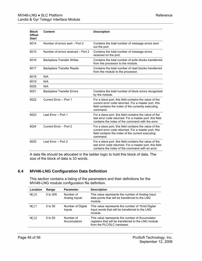
Block Offset Start
Content Description
6014 Number of errors sent – Port 2 Contains the total number of message errors sent out the port.
6015 Number of errors received – Port 2 Contains the total number of message errors received on the port.
6016 Backplane Transfer Writes Contains the total number of write blocks transferred from the processor to the module.
6017 Backplane Transfer Reads Contains the total number of read blocks transferred from the module to the processor.
6018 N/A 6019 N/A 6020 N/A 6021 Backplane Transfer Errors Contains the total number of block errors recognized
by the module. 6022 Current Error – Port 1 For a slave port, this field contains the value of the
current error code returned. For a master port, this field contains the index of the currently executing command.
6023 Last Error – Port 1 For a slave port, this field contains the value of the last error code returned. For a master port, this field contains the index of the command with the error.
6024 Current Error – Port 2 For a slave port, this field contains the value of the current error code returned. For a master port, this field contains the index of the current executing command.
6025 Last Error – Port 2 For a slave port, this field contains the value of the last error code returned. For a master port, this field contains the index of the command with an error.
A data file should be allocated in the ladder logic to hold this block of data. The size of the block of data is 33 words.
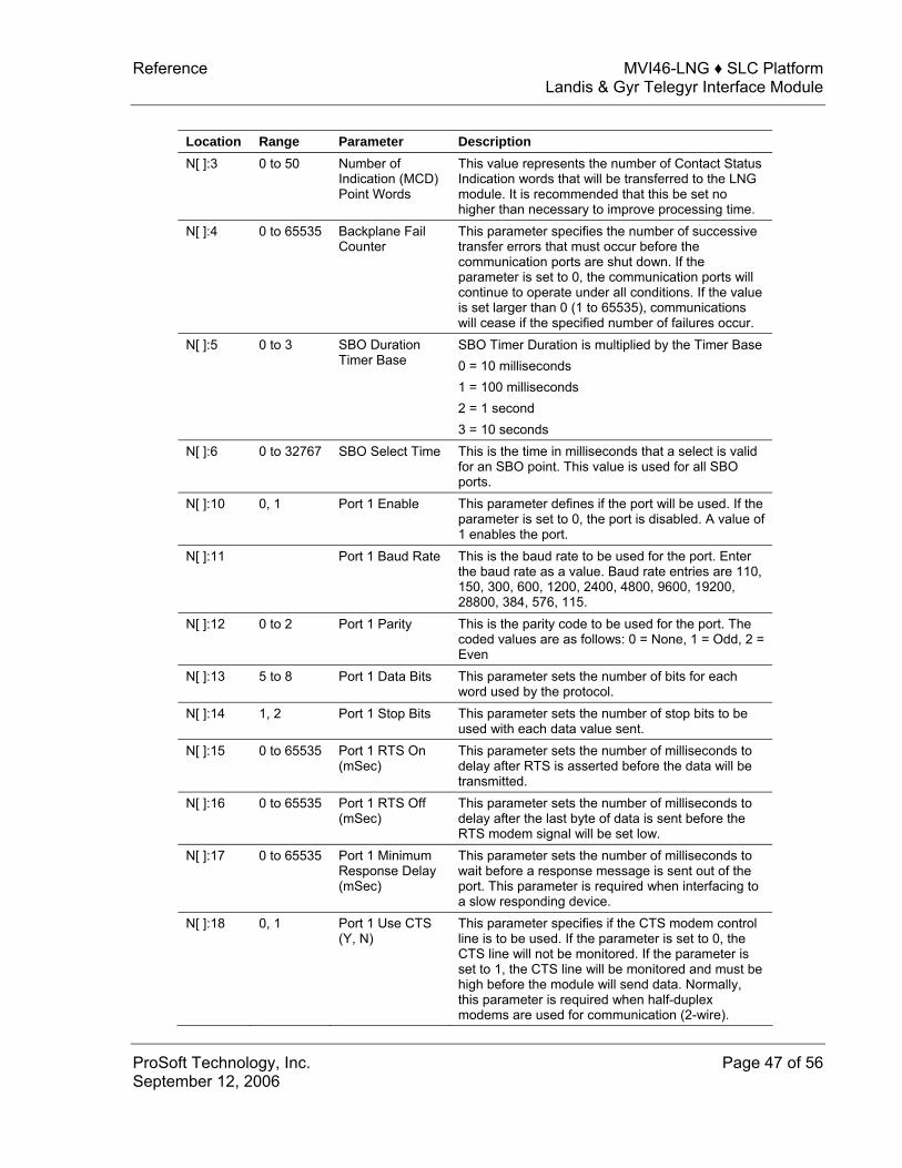
6.4 MVI46-LNG Configuration Data Definition
This section contains a listing of the parameters and their definitions for the MVI46-LNG module configuration file definition.
Location Range Parameter Description N[ ]:0 0 to 300 Number of
Analog Inputs This value represents the number of Analog Input data points that will be transferred to the LNG module.
N[ ]:1 0 to 50 Number of Digital Inputs
This value represents the number of 16-bit Digital Input words that will be transferred to the LNG module.
N[ ]:2 0 to 50 Number of Accumulators
This value represents the number of Accumulator registers that will be transferred to the LNG module from the PLC/SLC hardware.
Reference MVI46-LNG ♦ SLC Platform Landis & Gyr Telegyr Interface Module
ProSoft Technology, Inc. Page 47 of 56 September 12, 2006
Location Range Parameter Description N[ ]:3 0 to 50 Number of
Indication (MCD) Point Words
This value represents the number of Contact Status Indication words that will be transferred to the LNG module. It is recommended that this be set no higher than necessary to improve processing time.
N[ ]:4 0 to 65535 Backplane Fail Counter
This parameter specifies the number of successive transfer errors that must occur before the communication ports are shut down. If the parameter is set to 0, the communication ports will continue to operate under all conditions. If the value is set larger than 0 (1 to 65535), communications will cease if the specified number of failures occur.
N[ ]:5 0 to 3 SBO Duration Timer Base
SBO Timer Duration is multiplied by the Timer Base 0 = 10 milliseconds 1 = 100 milliseconds 2 = 1 second 3 = 10 seconds
N[ ]:6 0 to 32767 SBO Select Time This is the time in milliseconds that a select is valid for an SBO point. This value is used for all SBO ports.
N[ ]:10 0, 1 Port 1 Enable This parameter defines if the port will be used. If the parameter is set to 0, the port is disabled. A value of 1 enables the port.
N[ ]:11 Port 1 Baud Rate This is the baud rate to be used for the port. Enter the baud rate as a value. Baud rate entries are 110, 150, 300, 600, 1200, 2400, 4800, 9600, 19200, 28800, 384, 576, 115.
N[ ]:12 0 to 2 Port 1 Parity This is the parity code to be used for the port. The coded values are as follows: 0 = None, 1 = Odd, 2 = Even
N[ ]:13 5 to 8 Port 1 Data Bits This parameter sets the number of bits for each word used by the protocol.
N[ ]:14 1, 2 Port 1 Stop Bits This parameter sets the number of stop bits to be used with each data value sent.
N[ ]:15 0 to 65535 Port 1 RTS On (mSec)
This parameter sets the number of milliseconds to delay after RTS is asserted before the data will be transmitted.
N[ ]:16 0 to 65535 Port 1 RTS Off (mSec)
This parameter sets the number of milliseconds to delay after the last byte of data is sent before the RTS modem signal will be set low.
N[ ]:17 0 to 65535 Port 1 Minimum Response Delay (mSec)
This parameter sets the number of milliseconds to wait before a response message is sent out of the port. This parameter is required when interfacing to a slow responding device.
N[ ]:18 0, 1 Port 1 Use CTS (Y, N)
This parameter specifies if the CTS modem control line is to be used. If the parameter is set to 0, the CTS line will not be monitored. If the parameter is set to 1, the CTS line will be monitored and must be high before the module will send data. Normally, this parameter is required when half-duplex modems are used for communication (2-wire).

MVI46-LNG ♦ SLC Platform Reference Landis & Gyr Telegyr Interface Module
Page 48 of 56 ProSoft Technology, Inc. September 12, 2006
Location Range Parameter Description N[ ]:19 0 to 255 Port 1 Slave ID Slave address used by the host to access this port. N[ ]:20 0 to 65535 Port 1 Guard
Band Timer (mSec)
Not implemented at this time.
N[ ]:30 0, 1 Port 2 Enable This parameter defines if the port will be used. If the parameter is set to 0, the port is disabled. A value of 1 enables the port.
N[ ]:31 Port 2 Baud Rate This is the baud rate to be used for the port. Enter the baud rate as a value. Baud rate entries are 110, 150, 300, 600, 1200, 2400, 4800, 9600, 19200, 28800, 384, 576, 115.
N[ ]:32 0 to 4 Port 2 Parity This is the parity code to be used for the port. The coded values are as follows: 0 = None, 1 = Odd, 2 = Even
N[ ]:33 5 to 8 Port 2 Data Bits This parameter sets the number of bits for each word used by the protocol.
N[ ]:34 1, 2 Port 2 Stop Bits This parameter sets the number of stop bits to be used with each data value sent.
N[ ]:35 0 to 65535 Port 2 RTS On (mSec)
This parameter sets the number of milliseconds to delay after RTS is asserted before the data will be transmitted.
N[ ]:36 0 to 65535 Port 2 RTS Off (mSec)
This parameter sets the number of milliseconds to delay after the last byte of data is sent before the RTS modem signal will be set low.
N[ ]:37 0 to 65535 Port 2 Minimum Response Delay (mSec)
This parameter sets the number of milliseconds to wait before a response message is sent out of the port. This parameter is required when interfacing to a slow responding device.
N[ ]:38 0, 1 Port 2 Use CTS (Y, N)
This parameter specifies if the CTS modem control line is to be used. If the parameter is set to 0, the CTS line will not be monitored. If the parameter is set to 1, the CTS line will be monitored and must be high before the module will send data. Normally, this parameter is required when half-duplex modems are used for communication (2-wire).
N[ ]:39 0 to 255 Port 2 Slave ID Slave address used by the host to access this port. N[ ]:40 0 to 65535 Port 2 Guard
Band Timer (mSec)
Not implemented at this time.
6.5 Command Descriptions
The following table provides details on supported commands.
Command Command Description Analog Change Report – 0
This command is implemented in the module per the protocol specification. Up to 300 analog values are supported by the module.
Analog Force Report – 1
This command is implemented in the module per the protocol specification. Up to 300 analog values are supported by the module.

Reference MVI46-LNG ♦ SLC Platform Landis & Gyr Telegyr Interface Module
ProSoft Technology, Inc. Page 49 of 56 September 12, 2006
Command Command Description Analog Group Change Report - 2
This command is implemented in the module per the protocol specification. Up to 300 analog values are supported by the module.
Analog Group Force Report – 3
This command is implemented in the module per the protocol specification. Up to 300 analog values are supported by the module.
ADC Reference Force Report – 5
This command returns hardcoded values to the host for one ADC point. The following values are returned for the –90%, 0% and 90%. Percent Offset Binary Bipolar Hex 90 3890 1842 732 0 2048 0 800 –90 205 –1842 F32
Indication Change Report – 6
This command returns the status and memory bit values for the indication points that have had a change since the last host request. This data is derived from the data placed in the module when the indication point section of the M1 file is read. The actual logic to set and clear the indication bits must be performed by the ladder logic. Indication point data must be written to the M1 file when the ladder program detects an indication change. The M1 file is read in segments controlled by an internal block counter. The module will cycle through the block reading the entire data area. The indication point section of the database is read each time in addition to the normal data block. The indication block is tested for changes immediately after being read. When a change is found, the status bit corresponding to the indication point is updated and the memory bit is set if there has been more than one change since the last host query. This update method provides for an indication point update time of approximately 5 – 10ms depending on how many indication words are defined. The update time is lower with fewer points defined. Therefore the number of words of indication points should not be set any higher than necessary. When the host requests the indication point data, the change data is cleared in the module. At this time, the functionality to switch from the SOE mode to the Time based mode is not implemented. Note: If both ports are receiving indication change report requests, the first master to send a request will see change. The change is cleared after either master performs a read. In order for both masters to see the new data, both masters should use the indication force report.
Indication Force Report – 7
This command returns the status and memory bit values for the indication points that are requested by the host. This data is derived from the data placed in the module when the indication point section of the M1 file is read. The actual logic to set and clear the indication bits must be performed by the ladder logic. Indication point data must be written to the M1 file when the ladder program detects an indication change. At this time, the functionality to switch from the SOE mode to the Time based mode is not implemented.
Digital Input Force Report – 11
This command is implemented in the module per the protocol specification. Up to 50 analog values are supported by the module.
Accumulator Change Report – 12
This command is implemented in the module per the protocol specification. Up to 50 analog values are supported by the module.
Accumulator Force Report – 13
This command is implemented in the module per the protocol specification. Up to 50 analog values are supported by the module.

MVI46-LNG ♦ SLC Platform Reference Landis & Gyr Telegyr Interface Module
Page 50 of 56 ProSoft Technology, Inc. September 12, 2006
Command Command Description Analog Output – 20 This command is implemented in the module per the protocol
specification. Up to 50 analog values are supported by the module. SBO Select – 21 When an SBO select command is received from the host, the point is
selected and the timer is started. The point will remain selected until the point is operated upon, the timer expires, or another point is selected. The select time is determined by the SBO Select Time value.
SBO Operate – 22 The SBO Operate command will cause a previously selected point to be operated. An error response will be generated if the point has not been selected. There is no real limit on the number of SBO points that can be addressed by the host. The ladder logic implemented as part of the application will determine if a write command will move into the processor data table.
Digital Output – 23 This command is implemented in the module per the protocol specification, except that the upper 8 bits of the 24 bit write are disregarded. This allows 50 words of 16 bit digital output data to be addressed.
Accumulator Freeze – 24
This command is implemented in the module per the protocol specification. Up to 50 analog values are supported by the module.
Pulse Output – 25 This command is implemented in the module per the protocol specification. The module decodes the write command and moves the data to the processor in a series of data structures depending on the type and time base of the command. Through these data structures, support is provided to address 9 pulse points.
Pulse Train Output – 26 (Hold)
This command is not implemented at this time.
Restart RTU – 30 This command is implemented in the module per the protocol specification, performing a cold boot.
RTU Configuration – 31
This command is implemented in the module to support one rack of configuration data. The configuration data is moved to the module with a write to the M1 file.
Analog Deadbands – 34
This command is implemented in the module per the protocol specification. Up to 300 analog values are supported by the module.
Analog Group Defines – 35
This command is implemented per the protocol specification. Up to 300 analog values are supported by the module.
Accumulator Preset – 36
This command is implemented in the module per the protocol specification. Up to 300 preset values are supported by the module.
Continuation Request – 37
This command is implemented in the module per the protocol specification. It only pertains to functions 0, 1, 2, 3, and 7 as the other commands cannot return a message long enough to require a continuation.
Repeat Last Message – 38
This command is implemented in the module per the protocol specification.
Firmware Configuration – 39
This command is implemented in the module per the protocol specification. The value returned is the version level of the ProSoft firmware.
Exception Report – 63 This command is implemented in the module per the protocol specification. Not all of the exception codes are supported due to hardware dissimilarities between L&G and Rockwell Automation.

Support, Service & Warranty MVI46-LNG ♦ SLC Platform Landis & Gyr Telegyr Interface Module
ProSoft Technology, Inc. Page 51 of 56 September 12, 2006
Support, Service & Warranty ProSoft Technology, Inc. survives on its ability to provide meaningful support to its customers. Should any questions or problems arise, please feel free to contact us at:
Internet Web Site: http://www.prosoft-technology.com/support E-mail address: [email protected]
Phone (661) 716-5100 (661) 716-5101 (Fax)
Postal Mail ProSoft Technology, Inc. 1675 Chester Avenue, Fourth Floor Bakersfield, CA 93301
Before calling for support, please prepare yourself for the call. In order to provide the best and quickest support possible, we will most likely ask for the following information:
1 Product Version Number
2 System architecture
3 Module configuration and contents of configuration file
4 Module Operation
o Configuration/Debug status information o LED patterns
5 Information about the processor and user data files as viewed through RSLogix 500 and LED patterns on the processor
6 Details about the serial devices interfaced
An after-hours answering system allows pager access to one of our qualified technical and/or application support engineers at any time to answer the questions that are important to you.
Module Service and Repair
The MVI46-LNG device is an electronic product, designed and manufactured to function under somewhat adverse conditions. As with any product, through age, misapplication, or any one of many possible problems the device may require repair.
When purchased from ProSoft Technology, Inc., the device has a 1 year parts and labor warranty (3 years for RadioLinx) according to the limits specified in the

MVI46-LNG ♦ SLC Platform Support, Service & Warranty Landis & Gyr Telegyr Interface Module
Page 52 of 56 ProSoft Technology, Inc. September 12, 2006
warranty. Replacement and/or returns should be directed to the distributor from whom the product was purchased. If you must return the device for repair, obtain an RMA (Returned Material Authorization) number from ProSoft Technology, Inc. Please call the factory for this number, and print the number prominently on the outside of the shipping carton used to return the device.
General Warranty Policy – Terms and Conditions
ProSoft Technology, Inc. (hereinafter referred to as ProSoft) warrants that the Product shall conform to and perform in accordance with published technical specifications and the accompanying written materials, and shall be free of defects in materials and workmanship, for the period of time herein indicated, such warranty period commencing upon receipt of the Product. Limited warranty service may be obtained by delivering the Product to ProSoft in accordance with our product return procedures (on page 53) and providing proof of purchase and receipt date. Customer agrees to insure the Product or assume the risk of loss or damage in transit, to prepay shipping charges to ProSoft, and to use the original shipping container or equivalent. Contact ProSoft Customer Service for further information.
This warranty is limited to the repair and/or replacement, at ProSoft's election, of defective or non-conforming Product, and ProSoft shall not be responsible for the failure of the Product to perform specified functions, or any other non-conformance caused by or attributable to: (a) any misuse, misapplication, accidental damage, abnormal or unusually heavy use, neglect, abuse, alteration (b) failure of Customer to adhere to ProSoft’s specifications or instructions, (c) any associated or complementary equipment, software, or user-created programming including, but not limited to, programs developed with any EC1131-3 programming languages, “C” for example, and not furnished by ProSoft, (d) improper installation, unauthorized repair or modification (e) improper testing, or causes external to the product such as, but not limited to, excessive heat or humidity, power failure, power surges or natural disaster, compatibility with other hardware and software products introduced after the time of purchase, or products or accessories not manufactured by ProSoft; all of which components, software and products are provided as-is. In no event will ProSoft be held liable for any direct or indirect, incidental consequential damage, loss of data, or other malady arising from the purchase or use of ProSoft products.
ProSoft’s software or electronic products are designed and manufactured to function under adverse environmental conditions as described in the hardware specifications for this product. As with any product, however, through age, misapplication, or any one of many possible problems, the device may require repair.
ProSoft warrants its products to be free from defects in material and workmanship and shall conform to and perform in accordance with published technical specifications and the accompanying written materials for up to one year (12 months) from the date of original purchase (3 years for RadioLinx
Support, Service & Warranty MVI46-LNG ♦ SLC Platform Landis & Gyr Telegyr Interface Module
ProSoft Technology, Inc. Page 53 of 56 September 12, 2006
products) from ProSoft. If you need to return the device for repair, obtain an RMA (Returned Material Authorization) number from ProSoft Technology, Inc. in accordance with the RMA instructions below. Please call the factory for this number, and print the number prominently on the outside of the shipping carton used to return the device.
If the product is received within the warranty period ProSoft will repair or replace the defective product at our option and cost.
Warranty Procedure: Upon return of the hardware product ProSoft will, at its option, repair or replace the product at no additional charge, freight prepaid, except as set forth below. Repair parts and replacement product will be furnished on an exchange basis and will be either reconditioned or new. All replaced product and parts become the property of ProSoft. If ProSoft determines that the Product is not under warranty, it will, at the Customer's option, repair the Product using then current ProSoft standard rates for parts and labor, and return the product freight collect.
Limitation of Liability
EXCEPT AS EXPRESSLY PROVIDED HEREIN, PROSOFT MAKES NO WARRANT OF ANY KIND, EXPRESSED OR IMPLIED, WITH RESPECT TO ANY EQUIPMENT, PARTS OR SERVICES PROVIDED PURSUANT TO THIS AGREEMENT, INCLUDING BUT NOT LIMITED TO THE IMPLIED WARRANTIES OF MERCHANTABILITY AND FITNESS FOR A PARTICULAR PURPOSE. NEITHER PROSOFT OR ITS DEALER SHALL BE LIABLE FOR ANY OTHER DAMAGES, INCLUDING BUT NOT LIMITED TO DIRECT, INDIRECT, INCIDENTAL, SPECIAL OR CONSEQUENTIAL DAMAGES, WHETHER IN AN ACTION IN CONTRACT OR TORT (INCLUDING NEGLIGENCE AND STRICT LIABILITY), SUCH AS, BUT NOT LIMITED TO, LOSS OF ANTICIPATED PROFITS OR BENEFITS RESULTING FROM, OR ARISING OUT OF, OR IN CONNECTION WITH THE USE OR FURNISHING OF EQUIPMENT, PARTS OR SERVICES HEREUNDER OR THE PERFORMANCE, USE OR INABILITY TO USE THE SAME, EVEN IF ProSoft OR ITS DEALER'S TOTAL LIABILITY EXCEED THE PRICE PAID FOR THE PRODUCT.
Where directed by State Law, some of the above exclusions or limitations may not be applicable in some states. This warranty provides specific legal rights; other rights that vary from state to state may also exist. This warranty shall not be applicable to the extent that any provisions of this warranty are prohibited by any Federal, State or Municipal Law that cannot be preempted. Contact ProSoft Customer Service at (661) 716-5100 for more information.
RMA Procedures
In the event that repairs are required for any reason, contact ProSoft Technical Support at +1 661.716.5100. A Technical Support Engineer will ask you to

MVI46-LNG ♦ SLC Platform Support, Service & Warranty Landis & Gyr Telegyr Interface Module
Page 54 of 56 ProSoft Technology, Inc. September 12, 2006
perform several tests in an attempt to diagnose the problem. Simply calling and asking for a RMA without following our diagnostic instructions or suggestions will lead to the return request being denied. If, after these tests are completed, the module is found to be defective, we will provide the necessary RMA number with instructions on returning the module for repair.

Index MVI46-LNG ♦ SLC Platform Landis & Gyr Telegyr Interface Module
ProSoft Technology, Inc. Page 55 of 56 September 12, 2006
Index
A Accumulator Preset Data • 12 Analog Output Data • 12
B Backplane Data Transfer • 10
C Cable Connections • 41 Clearing a Fault Condition • 38 CMDS • 25 Cold Boot • 16 Command Control Blocks • 15 Command Descriptions • 48 Configuration Data Transfer • 15
D Database View Menu • 35 Diagnostics and Troubleshooting • 29 Digital Output Data • 12 Displaying the Current Page of Registers
Again • 36
E Exiting the Program • 35
F Functional Overview • 9
G General Concepts • 9 General Specifications • 5 General Warranty Policy – Terms and
Conditions • 52
H Hardware Specifications • 7
I Installing and Configuring the Module • 17
K Keystrokes • 30
L Ladder Logic • 21 LED Status Indicators • 37 Limitation of Liability • 53
M Main Logic Loop • 10 Main Menu • 32 MainRoutine • 21 Module Configuration Data • 15 Module Data • 19 Module Power Up • 9 Module Service and Repair • 51 Moving Back Through 5 Pages of Registers •
36 MVI46-LNG Configuration Data Definition •
46 MVI46-LNG Database Map • 19 MVI46-LNG Status Data Area • 45
N Navigation • 30 Normal Data Transfer • 12
O Opening the Data Analyzer Menu • 32 Opening the Database Menu • 33
P Physical • 6 Please Read This Notice • 2 Product Specifications • 5 Pulse Commands • 13
R Reading Status Data From the Module • 29 Reference • 41 Required Hardware • 30 Required Software • 31 Resetting diagnostic data • 33 Returning to the Main Menu • 37 RMA Procedures • 52, 53 RS-232 • 41 RS-232 -- Modem Connection • 42 RS-232 -- Null Modem Connection
(Hardware Handshaking) • 42
MVI46-LNG ♦ SLC Platform Index Landis & Gyr Telegyr Interface Module
Page 56 of 56 ProSoft Technology, Inc. September 12, 2006
RS-232 -- Null Modem Connection (No Hardware Handshaking) • 43
RS-232 Configuration/Debug Port • 43 RS-422 • 44 RS-485 • 44 RS-485 and RS-422 Tip • 44
S SBO Active Flag • 14 SBO Bit Address • 14 SBO Commands • 14 SBO Duration • 15 SBO Operation • 14 Setting Jumpers • 45 Skipping 500 Registers of Data • 36 SLC Interface • 7 Support, Service & Warranty • 51
T The Configuration/Debug Menu • 29 Transfer Routine • 23 Transferring Module Configuration to the
Processor • 34 Troubleshooting • 38
U Using the Configuration/Debug Port • 31
V Viewing Block Transfer Statistics • 33 Viewing Data in ASCII (Text) Format • 37 Viewing Data in Decimal Format • 36 Viewing Data in Floating Point Format • 37 Viewing Data in Hexadecimal Format • 37 Viewing Module Configuration • 33 Viewing Port Communication Status • 34 Viewing Port Configuration • 34 Viewing Register Pages • 36 Viewing the Next 100 Registers of Data • 36 Viewing the Previous 100 Registers of Data •
36 Viewing Version Information • 33
W Warm Boot • 16 Warm Booting the Module • 34 Write Configuration • 16 Write Time • 15
Y Your Feedback Please • 2


