205
MVI56-MCMR ControlLogix Platform Modbus Communication Module with Reduced Data Block February 11, 2011 USER MANUAL
MVI56-MCMR ControlLogix Platform
Modbus Communication Module with Reduced Data Block
February 11, 2011
USER MANUAL

Your Feedback Please
We always want you to feel that you made the right decision to use our products. If you have suggestions, comments, compliments or complaints about our products, documentation, or support, please write or call us.
How to Contact Us
ProSoft Technology 5201 Truxtun Ave., 3rd Floor Bakersfield, CA 93309 +1 (661) 716-5100 +1 (661) 716-5101 (Fax) www.prosoft-technology.com [email protected]
Copyright © 2011 ProSoft Technology, Inc., all rights reserved.
MVI56-MCMR User Manual
February 11, 2011
ProSoft Technology ®, ProLinx ®, inRAx ®, ProTalk ®, and RadioLinx ® are Registered Trademarks of ProSoft Technology, Inc. All other brand or product names are or may be trademarks of, and are used to identify products and services of, their respective owners.
ProSoft Technology® Product Documentation
In an effort to conserve paper, ProSoft Technology no longer includes printed manuals with our product shipments. User Manuals, Datasheets, Sample Ladder Files, and Configuration Files are provided on the enclosed CD-ROM, and are available at no charge from our web site: www.prosoft-technology.com
Printed documentation is available for purchase. Contact ProSoft Technology for pricing and availability.
North America: +1.661.716.5100
Asia Pacific: +603.7724.2080
Europe, Middle East, Africa: +33 (0) 5.3436.87.20
Latin America: +1.281.298.9109
Important Installation Instructions
Power, Input, and Output (I/O) wiring must be in accordance with Class I, Division 2 wiring methods, Article 501-4 (b) of the National Electrical Code, NFPA 70 for installation in the U.S., or as specified in Section 18-1J2 of the Canadian Electrical Code for installations in Canada, and in accordance with the authority having jurisdiction. The following warnings must be heeded:
A WARNING - EXPLOSION HAZARD - SUBSTITUTION OF COMPONENTS MAY IMPAIR SUITABILITY FOR CLASS I, DIV. 2;
B WARNING - EXPLOSION HAZARD - WHEN IN HAZARDOUS LOCATIONS, TURN OFF POWER BEFORE REPLACING OR WIRING MODULES
C WARNING - EXPLOSION HAZARD - DO NOT DISCONNECT EQUIPMENT UNLESS POWER HAS BEEN SWITCHED OFF OR THE AREA IS KNOWN TO BE NON-HAZARDOUS.
D THIS DEVICE SHALL BE POWERED BY CLASS 2 OUTPUTS ONLY.
MVI (Multi Vendor Interface) Modules
WARNING - EXPLOSION HAZARD - DO NOT DISCONNECT EQUIPMENT UNLESS POWER HAS BEEN SWITCHED OFF OR THE AREA IS KNOWN TO BE NON-HAZARDOUS.
AVERTISSEMENT - RISQUE D'EXPLOSION - AVANT DE DÉCONNECTER L'ÉQUIPEMENT, COUPER LE COURANT OU S'ASSURER QUE L'EMPLACEMENT EST DÉSIGNÉ NON DANGEREUX.
Warnings
North America Warnings
Power, Input, and Output (I/O) wiring must be in accordance with Class I, Division 2 wiring methods, Article 501-4 (b) of the National Electrical Code, NFPA 70 for installation in the U.S., or as specified in Section 18-1J2 of the Canadian Electrical Code for installations in Canada, and in accordance with the authority having jurisdiction. The following warnings must be heeded:
A Warning - Explosion Hazard - Substitution of components may impair suitability for Class I, Division 2. B Warning - Explosion Hazard - When in hazardous locations, turn off power before replacing or rewiring modules. C Warning - Explosion Hazard - Do not disconnect equipment unless power has been switched off or the area is
known to be non-hazardous.
Avertissement - Risque d'explosion - Avant de déconnecter l'équipement, couper le courant ou s'assurer que l'emplacement est désigné non dangereux.
D Suitable for use in Class I, Division 2 Groups A, B, C and D Hazardous Locations or Non-Hazardous Locations.
ATEX Warnings and Conditions of Safe Usage
Power, Input, and Output (I/O) wiring must be in accordance with the authority having jurisdiction.
A Warning - Explosion Hazard - When in hazardous locations, turn off power before replacing or wiring modules. B Warning - Explosion Hazard - Do not disconnect equipment unless power has been switched off or the area is
known to be non-hazardous. C These products are intended to be mounted in an IP54 enclosure. The devices shall provide external means to
prevent the rated voltage being exceeded by transient disturbances of more than 40%. This device must be used only with ATEX certified backplanes.
D DO NOT OPEN WHEN ENERGIZED.
Battery Life Advisory
The MVI46, MVI56, MVI56E, MVI69, and MVI71 modules use a rechargeable Lithium Vanadium Pentoxide battery to backup the real-time clock and CMOS. The battery should last for the life of the module. The module must be powered for approximately twenty hours before the battery becomes fully charged. After it is fully charged, the battery provides backup power for the CMOS setup and the real-time clock for approximately 21 days. When the battery is fully discharged, the module will revert to the default BIOS and clock settings.
Note: The battery is not user replaceable.
Markings
Electrical Ratings
� Backplane Current Load: 800 mA @ 5.1 Vdc; 3 mA @ 24 Vdc � Operating Temperature: 0°C to 60°C (32°F to 140°F) � Storage Temperature: -40°C to 85°C (-40°F to 185°F) � Shock: 30 g, operational; 50 g, non-operational; Vibration: 5 g from 10 Hz to 150 Hz � Relative Humidity: 5% to 95% with no condensation � All phase conductor sizes must be at least 1.3 mm(squared) and all earth ground conductors must be at least
4mm(squared).
Label Markings
ATEX
II 3 G
EEx nA IIC T6
0°C <= Ta <= 60°C
cULus
E183151
Class I Div 2 Groups A,B,C,D
T6
-30°C <= Ta <= 60°C
Agency Approvals and Certifications
Agency Applicable Standard
RoHS
CE EMC-EN61326-1:2006; EN61000-6-4:2007
ATEX EN60079-15:2003
cULus UL508; UL1604; CSA 22.2 No. 142 & 213
CB Safety CA/10533/CSA IEC 61010-1 Ed.2; CB 243333-2056722 (2090408)
GOST-R EN 61010
CSA EN 61010
243333 ME06 E183151
MVI56-MCMR ♦ ControlLogix Platform Contents Modbus Communication Module with Reduced Data Block User Manual
ProSoft Technology, Inc. Page 5 of 205 February 11, 2011
Contents
Your Feedback Please ........................................................................................................................ 2
How to Contact Us .............................................................................................................................. 2
ProSoft Technology® Product Documentation .................................................................................... 2
Important Installation Instructions ....................................................................................................... 3
MVI (Multi Vendor Interface) Modules ................................................................................................ 3
Warnings ............................................................................................................................................. 3
Battery Life Advisory ........................................................................................................................... 3
Guide to the MVI56-MCMR User Manual 9
1 Start Here 11
1.1 System Requirements ............................................................................................. 12
1.2 Deployment Checklist .............................................................................................. 13
1.3 Package Contents ................................................................................................... 15
1.4 Setting Jumpers ...................................................................................................... 16
1.5 Installing the Module in the Rack ............................................................................ 17
2 Using the RSLogix 5000 v16 Add-On Instruction 19
2.1 Creating a New RSLogix 5000 Project .................................................................... 21
2.2 Creating the Remote Network ................................................................................. 22
2.3 Creating the Module - Remote Rack ....................................................................... 24
2.4 Creating the Module ................................................................................................ 27
2.5 Importing the Ladder Rung...................................................................................... 30
2.5.1 Adding Multiple Modules (Optional) ........................................................................ 33
2.5.2 Configuring the Path for Message Blocks ............................................................... 38
2.6 Adjusting the Input and Output Array Sizes ............................................................ 39
2.7 Connecting Your PC to the ControlLogix Processor ............................................... 41
2.8 Downloading the Sample Program to the Processor .............................................. 42
2.8.1 Configuring the RSLinx Driver for the PC COM Port .............................................. 43
3 Configuring the MVI56-MCMR Module 45
3.1 Using ProSoft Configuration Builder ....................................................................... 46
3.1.1 Setting Up the Project ............................................................................................. 46
3.1.2 Renaming PCB Objects .......................................................................................... 48
3.2 Downloading the Project to the Module Using a Serial COM port .......................... 50
4 Configuration as a Modbus Master 51
4.1 Overview.................................................................................................................. 52
4.2 Backplane Configuration ......................................................................................... 53
4.3 Port Configuration ................................................................................................... 55
4.4 Master Command Configuration ............................................................................. 57
4.5 Other Modbus Addressing Schemes ...................................................................... 61
4.6 Master Command Examples ................................................................................... 63
Contents MVI56-MCMR ♦ ControlLogix Platform User Manual Modbus Communication Module with Reduced Data Block
Page 6 of 205 ProSoft Technology, Inc. February 11, 2011
4.6.1 Read Holding Registers 4x (Modbus Function Code 3) ......................................... 63
4.6.2 Read Input Registers 3xxxxx (Modbus Function Code 4) ...................................... 64
4.6.3 Read Coil Status 0x (Modbus Function Code 1) .................................................... 65
4.6.4 Read Input Status 1x (Modbus Function Code 2) .................................................. 66
4.6.5 Preset (Write) Single Coil 0x (Modbus Function Code 5) ....................................... 67
4.6.6 Write Multiple Coils 0xxx (Modbus Function Code 15) ........................................... 68
4.6.7 Preset (Write) Single Register 4x (Modbus Function Code 6) ............................... 69
4.6.8 Preset (Write) Multiple Registers 4x (Modbus Function Code 16) ......................... 70
4.7 Floating-Point Data Handling (Modbus Master) ..................................................... 71
4.7.1 Read Floating-Point Data ....................................................................................... 71
4.7.2 Read Multiple Floating-Point Registers .................................................................. 72
4.7.3 Write Floats to Slave Device ................................................................................... 74
4.7.4 Read Floats with Single Modbus Register Address (Enron/Daniel Float) .............. 75
4.7.5 Write to Enron/Daniel Floats ................................................................................... 77
5 Configuration as a Modbus Slave 79
5.1 Overview ................................................................................................................. 80
5.2 Configuration File Settings ...................................................................................... 81
5.2.1 Modbus Memory Map ............................................................................................. 83
5.2.2 Customizing the Memory Map ................................................................................ 84
5.3 Slave Configuration ................................................................................................ 86
5.4 Floating-Point Data Handling (Modbus Slave) ....................................................... 88
5.4.1 Enron/Daniel Float Configuration............................................................................ 89
6 Verify Communication 91
6.1 Verify Master Communications ............................................................................... 92
6.1.1 Status Data Definition as a Master ......................................................................... 92
6.1.2 Command Error Codes ........................................................................................... 94
6.1.3 MCM Status Data ................................................................................................... 98
6.2 Verify Slave Communications ................................................................................. 99
6.2.1 Status Data Definition as a Slave ......................................................................... 100
7 Ladder Logic 103
7.1 MVI56-MCMR User Defined Data Types ............................................................. 104
7.1.1 Module Status Data and Variables (MCMRModuleDef) ....................................... 104
8 Diagnostics and Troubleshooting 109
8.1 LED Status Indicators ........................................................................................... 110
8.2 Using ProSoft Configuration Builder (PCB) for Diagnostics ................................. 111
8.2.1 Using the Diagnostic Window in ProSoft Configuration Builder ........................... 111
8.2.2 Navigation ............................................................................................................. 113
8.2.3 Main Menu ............................................................................................................ 114
8.2.4 Data Analyzer ....................................................................................................... 119
8.2.5 Modbus Database View Menu .............................................................................. 124
8.2.6 Master Command Error List Menu........................................................................ 125
8.2.7 Master Command List Menu ................................................................................. 126
8.3 Reading Status Data from the Module ................................................................. 128
8.4 Communication Error Codes ................................................................................ 129
MVI56-MCMR ♦ ControlLogix Platform Contents Modbus Communication Module with Reduced Data Block User Manual
ProSoft Technology, Inc. Page 7 of 205 February 11, 2011
8.4.1 Clearing a Fault Condition ..................................................................................... 131
8.4.2 Troubleshooting ..................................................................................................... 132
9 Reference 133
9.1 About the MODBUS Protocol ................................................................................ 134
9.2 Specifications ........................................................................................................ 135
9.2.1 General Specifications .......................................................................................... 135
9.2.2 Hardware Specifications........................................................................................ 136
9.2.3 General Specifications - Modbus Master/Slave .................................................... 137
9.2.4 Functional Specifications....................................................................................... 137
9.3 Functional Overview .............................................................................................. 139
9.3.1 Processor/Module Data Transfers ........................................................................ 139
9.3.2 Normal Data Transfer Blocks ................................................................................ 142
9.3.3 Special Function Blocks ........................................................................................ 143
9.3.4 Master Driver ......................................................................................................... 157
9.3.5 Slave Driver ........................................................................................................... 159
9.3.6 MCMPort ............................................................................................................... 160
9.4 Cable Connections ................................................................................................ 161
9.4.1 RS-232 Configuration/Debug Port ........................................................................ 161
9.4.2 RS-232 Application Port(s) ................................................................................... 161
9.4.3 RS-422 .................................................................................................................. 164
9.4.4 RS-485 Application Port(s) .................................................................................... 164
9.4.5 DB9 to RJ45 Adaptor (Cable 14) .......................................................................... 165
9.5 MVI56-MCMR Status Data Definition .................................................................... 166
9.6 Modbus Protocol Specification .............................................................................. 168
9.6.1 Commands Supported by the Module ................................................................... 168
9.6.2 Read Coil Status (Function Code 01) ................................................................... 169
9.6.3 Read Input Status (Function Code 02) .................................................................. 170
9.6.4 Read Holding Registers (Function Code 03) ........................................................ 171
9.6.5 Read Input Registers (Function Code 04) ............................................................. 172
9.6.6 Force Single Coil (Function Code 05) ................................................................... 173
9.6.7 Preset Single Register (Function Code 06) ........................................................... 174
9.6.8 Diagnostics (Function Code 08) ............................................................................ 174
9.6.9 Force Multiple Coils (Function Code 15) ............................................................... 176
9.6.10 Preset Multiple Registers (Function Code 16) ...................................................... 177
9.6.11 Modbus Exception Responses .............................................................................. 178
9.7 Using the Sample Program - RSLogix 5000 Version 15 and earlier ..................... 181
9.7.1 Adding the Sample Ladder to an Existing Application .......................................... 181
9.7.2 Add the Module to the Project ............................................................................... 181
9.7.3 Copying the User Defined Data Types .................................................................. 184
9.7.4 Copy Sample Controller Tags ............................................................................... 184
9.7.5 Add the Ladder Logic ............................................................................................ 185
9.7.6 Ladder Logic - RSLogix Version 15 and Lower .................................................... 185
10 Support, Service & Warranty 195
Contacting Technical Support ......................................................................................................... 195
10.1 Return Material Authorization (RMA) Policies and Conditions.............................. 197
10.1.1 Returning Any Product .......................................................................................... 197
10.1.2 Returning Units Under Warranty ........................................................................... 198
10.1.3 Returning Units Out of Warranty ........................................................................... 198
10.2 LIMITED WARRANTY ........................................................................................... 199
Contents MVI56-MCMR ♦ ControlLogix Platform User Manual Modbus Communication Module with Reduced Data Block
Page 8 of 205 ProSoft Technology, Inc. February 11, 2011
10.2.1 What Is Covered By This Warranty ...................................................................... 199
10.2.2 What Is Not Covered By This Warranty ................................................................ 200
10.2.3 Disclaimer Regarding High Risk Activities ............................................................ 200
10.2.4 Intellectual Property Indemnity ............................................................................. 201
10.2.5 Disclaimer of all Other Warranties ........................................................................ 201
10.2.6 Limitation of Remedies ** ..................................................................................... 202
10.2.7 Time Limit for Bringing Suit ................................................................................... 202
10.2.8 No Other Warranties ............................................................................................. 202
10.2.9 Allocation of Risks ................................................................................................ 202
10.2.10 Controlling Law and Severability .......................................................................... 202
Index 203
MVI56-MCMR ♦ ControlLogix Platform Guide to the MVI56-MCMR User Manual Modbus Communication Module with Reduced Data Block User Manual
ProSoft Technology, Inc. Page 9 of 205 February 11, 2011
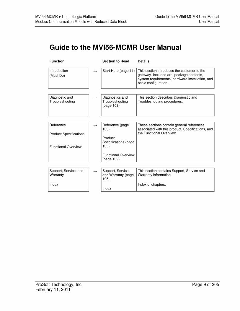
Guide to the MVI56-MCMR User Manual
Function Section to Read Details
Introduction (Must Do)
→ Start Here (page 11) This section introduces the customer to the gateway. Included are: package contents, system requirements, hardware installation, and basic configuration.
Diagnostic and Troubleshooting
→ Diagnostics and Troubleshooting (page 109)
This section describes Diagnostic and Troubleshooting procedures.
Reference Product Specifications Functional Overview
→ Reference (page 133) Product Specifications (page 135) Functional Overview (page 139)
These sections contain general references associated with this product, Specifications, and the Functional Overview.
Support, Service, and Warranty Index
→ Support, Service and Warranty (page 195) Index
This section contains Support, Service and Warranty information. Index of chapters.

Guide to the MVI56-MCMR User Manual MVI56-MCMR ♦ ControlLogix Platform User Manual Modbus Communication Module with Reduced Data Block
Page 10 of 205 ProSoft Technology, Inc. February 11, 2011
MVI56-MCMR ♦ ControlLogix Platform Start Here Modbus Communication Module with Reduced Data Block User Manual
ProSoft Technology, Inc. Page 11 of 205 February 11, 2011
1 Start Here
In This Chapter
� System Requirements ........................................................................... 12
� Deployment Checklist ............................................................................ 13
� Package Contents ................................................................................. 15
� Setting Jumpers .................................................................................... 16
� Installing the Module in the Rack ........................................................... 17
To get the most benefit from this User Manual, you should have the following skills: � Rockwell Automation® RSLogix™ software: launch the program, configure
ladder logic, and transfer the ladder logic to the processor � Microsoft Windows: install and launch programs, execute menu commands,
navigate dialog boxes, and enter data � Hardware installation and wiring: install the module, and safely connect
MCMR and ControlLogix devices to a power source and to the MVI56-MCMR module’s application port(s)
Start Here MVI56-MCMR ♦ ControlLogix Platform User Manual Modbus Communication Module with Reduced Data Block
Page 12 of 205 ProSoft Technology, Inc. February 11, 2011
1.1 System Requirements
The MVI56-MCMR module requires the following minimum hardware and software components: � Rockwell Automation ControlLogix™ processor, with compatible power
supply and one free slot in the rack, for the MVI56-MCMR module. The module requires 800 mA of available power.
� Rockwell Automation RSLogix 5000 programming software version 2.51 or higher
� Rockwell Automation RSLinx communication software � Pentium® II 450 MHz minimum. Pentium III 733 MHz (or better)
recommended � Supported operating systems:
o Microsoft Windows XP Professional with Service Pack 1 or 2 o Microsoft Windows 2000 Professional with Service Pack 1, 2, or 3 o Microsoft Windows Server 2003
� 128 Mbytes of RAM minimum, 256 Mbytes of RAM recommended � 100 Mbytes of free hard disk space (or more based on application
requirements) � 256-color VGA graphics adapter, 800 x 600 minimum resolution (True Color
1024 × 768 recommended) � CD-ROM drive � ProSoft Configuration Builder, HyperTerminal or other terminal emulator
program.
Note: You can install the module in a local or remote rack. For remote rack installation, the module requires EtherNet/IP or ControlNet communication with the processor.
MVI56-MCMR ♦ ControlLogix Platform Start Here Modbus Communication Module with Reduced Data Block User Manual
ProSoft Technology, Inc. Page 13 of 205 February 11, 2011
1.2 Deployment Checklist
Before you begin configuring the module, consider the following questions. Your answers will help you determine the scope of your project and the configuration requirements for a successful deployment. 1 ____________ Are you creating a new application or integrating the module
into an existing application? Most applications can use the Sample Ladder Logic without any edits to the Sample Program.
2 ____________ Which slot number in the chassis will the MVI56-MCMR module occupy? For communication to occur you must enter the correct slot number in the sample program.
3 ____________ Are RSLogix 5000 and RSLinx installed? RSLogix and RSLinx are required to communicate to the ControlLogix processor (1756-L1, L55, L61 & L63). Sample Ladder programs are available for many versions of RSLogix 5000.
4 ____________ How many words of data do you need to transfer in your application (from ControlLogix to Module / to ControlLogix from Module)? The MVI56-MCMR module can transfer a maximum of 5000 (16-bit) registers to/from the ControlLogix processor. The Sample Ladder transfers 600 words to the ControlLogix processor (into the Read Data array) and obtains 600 words from the ControlLogix processor (from the Write Data array).
5 ____________ Will you be using the module as a Modbus Master or Modbus Slave? Will you be transferring data using Modbus RTU or Modbus ASCII? Modbus is a master/slave network. Only one master is allowed on the Com line (max 32 devices/RS485). The Master is responsible for polling data from the slaves on the network.
6 ____________ For a Modbus Master, what devices (node ID) and Modbus addresses do you need to exchange data with on the Modbus network? As a Modbus master, you must know the node ID # of the slave devices you wish to obtain data from, as well as the Modbus address (coil 0001, register 4001 and so on) of the data that must be read from or written to that slave device.
7 ____________ For a Modbus Slave, how many words or bits of data do you need to send to the master device? The MVI56-MCMR module can send data to a Modbus master as 0x coil data, 1x input coil data, 3x input registers and 4x holding registers. The sample program transfers 600 (16-bit) words or 9600 bits to the ControlLogix processor, and 600w or 18 bits from the ControlLogix processor.
8 Serial Communication Parameters for the Modbus network: ____________ Baud rate? ____________ Data bits? ____________ Parity? ____________ Stop bits?
Start Here MVI56-MCMR ♦ ControlLogix Platform User Manual Modbus Communication Module with Reduced Data Block
Page 14 of 205 ProSoft Technology, Inc. February 11, 2011
Required for master and slave configurations. 9 ____________ Wiring type to be used (RS232, 422 or 485). Set by jumper
settings (page 16). Required for proper implementation of the module in master and slave configurations.
Note: If you are installing your module into a new system and plan to use our Sample Ladder Logic, refer to the Quick Start Guide for simple installation procedures. � For version 16 or newer of RSLogix 5000, refer to Using the RSLogix 5000 v16 Add-On
Instruction (page 19). � For NEW system installations, refer to Sample Ladder Logic in New Application. � For EXISTING system installations, refer to Integrating the Sample Ladder Logic into an
Existing Project (page 181). Note: Most applications can use the Sample Ladder Logic without any edits to the sample program.
MVI56-MCMR ♦ ControlLogix Platform Start Here Modbus Communication Module with Reduced Data Block User Manual
ProSoft Technology, Inc. Page 15 of 205 February 11, 2011
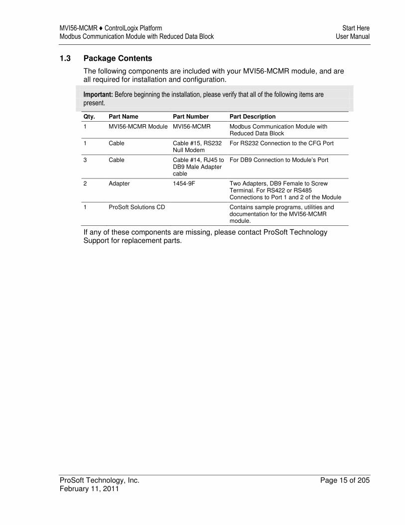
1.3 Package Contents
The following components are included with your MVI56-MCMR module, and are all required for installation and configuration.
Important: Before beginning the installation, please verify that all of the following items are present.
Qty. Part Name Part Number Part Description
1 MVI56-MCMR Module MVI56-MCMR Modbus Communication Module with Reduced Data Block
1 Cable Cable #15, RS232 Null Modem
For RS232 Connection to the CFG Port
3 Cable Cable #14, RJ45 to DB9 Male Adapter cable
For DB9 Connection to Module’s Port
2 Adapter 1454-9F Two Adapters, DB9 Female to Screw Terminal. For RS422 or RS485 Connections to Port 1 and 2 of the Module
1 ProSoft Solutions CD Contains sample programs, utilities and documentation for the MVI56-MCMR module.
If any of these components are missing, please contact ProSoft Technology Support for replacement parts.
Start Here MVI56-MCMR ♦ ControlLogix Platform User Manual Modbus Communication Module with Reduced Data Block
Page 16 of 205 ProSoft Technology, Inc. February 11, 2011
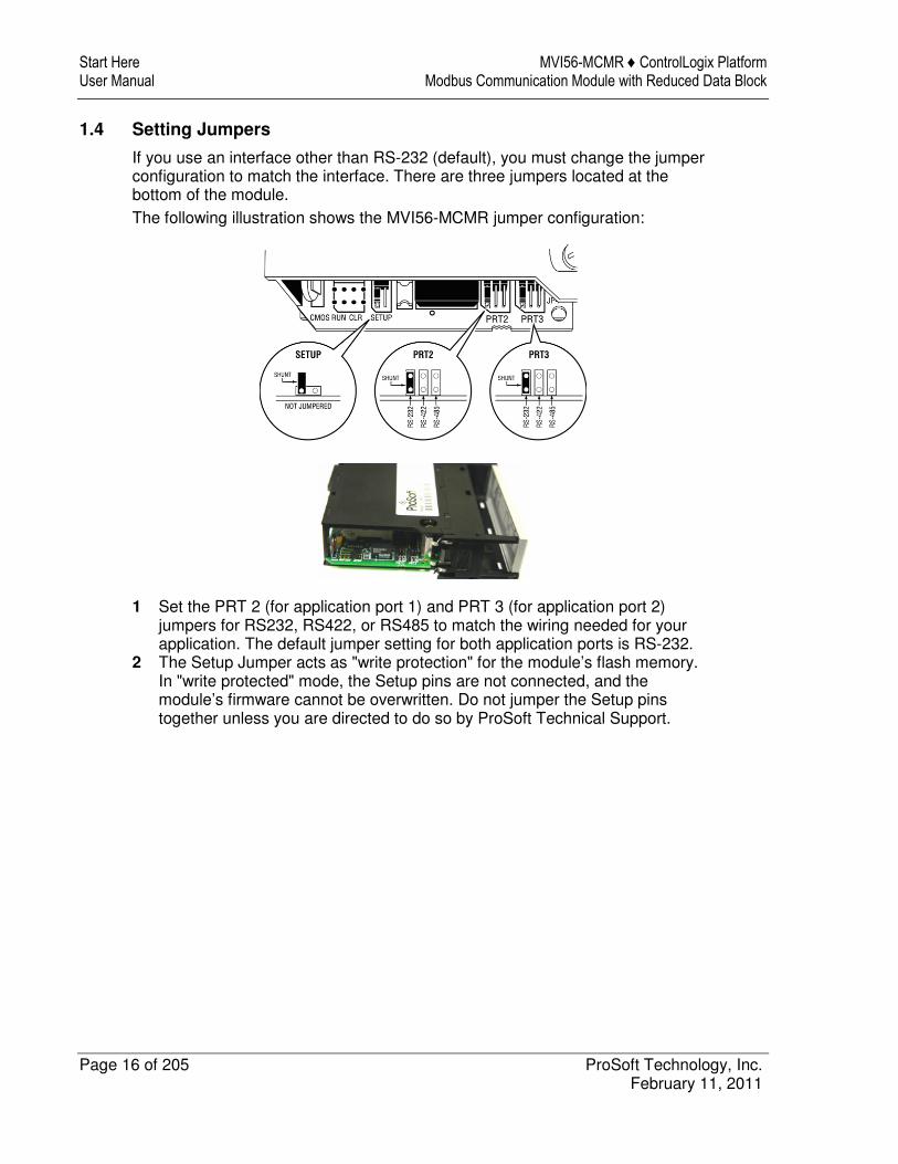
1.4 Setting Jumpers
If you use an interface other than RS-232 (default), you must change the jumper configuration to match the interface. There are three jumpers located at the bottom of the module. The following illustration shows the MVI56-MCMR jumper configuration:
1 Set the PRT 2 (for application port 1) and PRT 3 (for application port 2) jumpers for RS232, RS422, or RS485 to match the wiring needed for your application. The default jumper setting for both application ports is RS-232.
2 The Setup Jumper acts as "write protection" for the module’s flash memory. In "write protected" mode, the Setup pins are not connected, and the module’s firmware cannot be overwritten. Do not jumper the Setup pins together unless you are directed to do so by ProSoft Technical Support.
MVI56-MCMR ♦ ControlLogix Platform Start Here Modbus Communication Module with Reduced Data Block User Manual
ProSoft Technology, Inc. Page 17 of 205 February 11, 2011
1.5 Installing the Module in the Rack
If you have not already installed and configured your ControlLogix processor and power supply, please do so before installing the MVI56-MCMR module. Refer to your Rockwell Automation product documentation for installation instructions.
Warning: You must follow all safety instructions when installing this or any other electronic devices. Failure to follow safety procedures could result in damage to hardware or data, or even serious injury or death to personnel. Refer to the documentation for each device you plan to connect to verify that suitable safety procedures are in place before installing or servicing the device.
After you have checked the placement of the jumpers, insert MVI56-MCMR into the ControlLogix chassis. Use the same technique recommended by Rockwell Automation to remove and install ControlLogix modules.
Warning: When you insert or remove the module while backplane power is on, an electrical arc can occur. This could cause an explosion in hazardous location installations. Verify that power is removed or the area is non-hazardous before proceeding. Repeated electrical arcing causes excessive wear to contacts on both the module and its mating connector. Worn contacts may create electrical resistance that can affect module operation.
1 Turn power OFF. 2 Align the module with the top and bottom guides, and slide it into the rack
until the module is firmly against the backplane connector.
Start Here MVI56-MCMR ♦ ControlLogix Platform User Manual Modbus Communication Module with Reduced Data Block
Page 18 of 205 ProSoft Technology, Inc. February 11, 2011
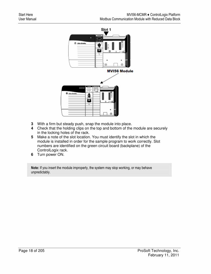
3 With a firm but steady push, snap the module into place. 4 Check that the holding clips on the top and bottom of the module are securely
in the locking holes of the rack. 5 Make a note of the slot location. You must identify the slot in which the
module is installed in order for the sample program to work correctly. Slot numbers are identified on the green circuit board (backplane) of the ControlLogix rack.
6 Turn power ON.
Note: If you insert the module improperly, the system may stop working, or may behave unpredictably.
MVI56-MCMR ♦ ControlLogix Platform Using the RSLogix 5000 v16 Add-On Instruction Modbus Communication Module with Reduced Data Block User Manual
ProSoft Technology, Inc. Page 19 of 205 February 11, 2011
2 Using the RSLogix 5000 v16 Add-On Instruction
In This Chapter
� Creating a New RSLogix 5000 Project .................................................. 21
� Creating the Remote Network ............................................................... 22
� Creating the Module - Remote Rack ..................................................... 24
� Creating the Module .............................................................................. 27
� Importing the Ladder Rung .................................................................... 30
� Adjusting the Input and Output Array Sizes ........................................... 39
� Connecting Your PC to the ControlLogix Processor .............................. 41
� Downloading the Sample Program to the Processor ............................. 42
Important: If you are using an older version of RSLogix 5000 (version 15 or older), please refer to Using the Sample Program in a New Application or Using the Sample Program in an Existing Application (page 181).
If you have RSLogix 5000 version 16 or newer, you can use an Add-On Instruction to simplify the task of configuring the module, either as a new application, or within an existing application. The ProSoft Solutions CD-ROM included in the package with the module contains ladder logic, product manuals, and utility programs for all ProSoft Technology products.
Using the RSLogix 5000 v16 Add-On Instruction MVI56-MCMR ♦ ControlLogix Platform User Manual Modbus Communication Module with Reduced Data Block
Page 20 of 205 ProSoft Technology, Inc. February 11, 2011
Copy the manuals and sample program from the CD-ROM
1 Insert the ProSoft Solutions CD-ROM into the CD drive of your PC. Wait for the startup screen to appear.
2 On the startup screen, click Product Documentation. This action opens an Explorer window. Files are arranged by type: o The Ladder Logic folder contains sample programs for each module,
arranged by processor type, and then by product name. The sample programs for your module are in the ControlLogix/MVI56/MVI56-MCMR folder.
o The Manuals folder contains product manuals and datasheets in Adobe Acrobat Reader format (PDF) for each module, arranged in the same way as the Ladder Logic folder.
o The Utilities folder contains additional programs and tools required for some ProSoft modules. Refer to your user manual to determine if you need to use or install any of these additional tools.
3 In the Explorer window, navigate to the files you need, and then copy them to a location on your hard drive.
Download the manuals and sample program from the ProSoft Technology web site
You can always download the latest version of the sample ladder logic and user manuals for the MVI56-MCMR module from the ProSoft Technology web site, at www.prosoft-technology.com/support/downloads From that link, navigate to the download page for your module and choose the sample ladder program to download for your version of RSLogix 5000 and your processor.
MVI56-MCMR ♦ ControlLogix Platform Using the RSLogix 5000 v16 Add-On Instruction Modbus Communication Module with Reduced Data Block User Manual
ProSoft Technology, Inc. Page 21 of 205 February 11, 2011
2.1 Creating a New RSLogix 5000 Project
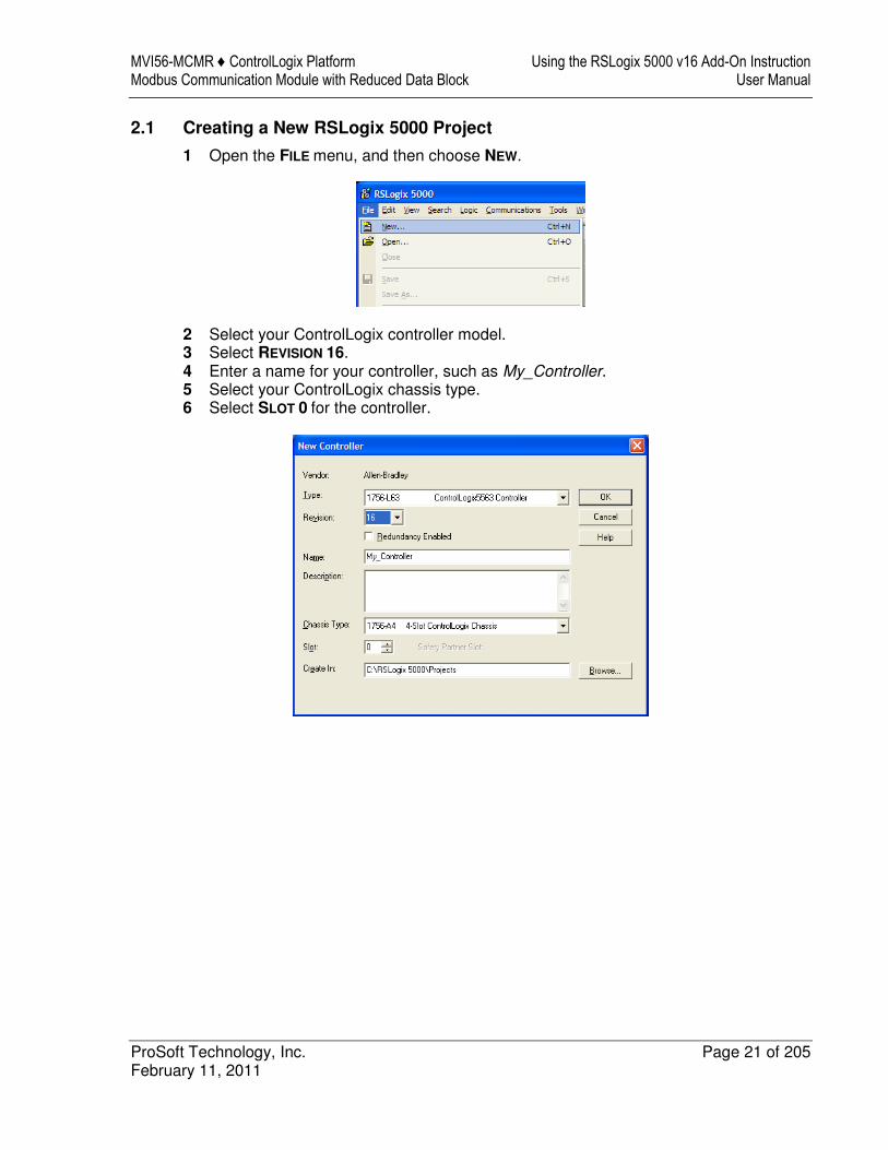
1 Open the FILE menu, and then choose NEW.
2 Select your ControlLogix controller model. 3 Select REVISION 16. 4 Enter a name for your controller, such as My_Controller. 5 Select your ControlLogix chassis type. 6 Select SLOT 0 for the controller.
Using the RSLogix 5000 v16 Add-On Instruction MVI56-MCMR ♦ ControlLogix Platform User Manual Modbus Communication Module with Reduced Data Block
Page 22 of 205 ProSoft Technology, Inc. February 11, 2011
2.2 Creating the Remote Network
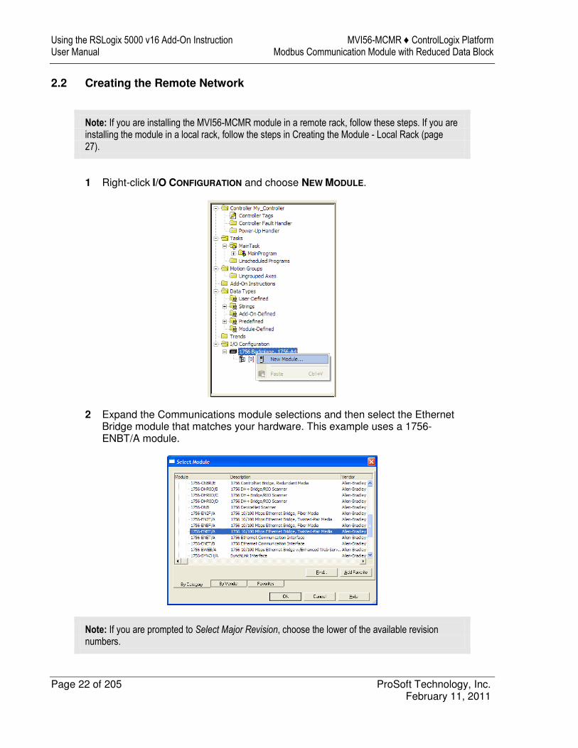
Note: If you are installing the MVI56-MCMR module in a remote rack, follow these steps. If you are installing the module in a local rack, follow the steps in Creating the Module - Local Rack (page 27).
1 Right-click I/O CONFIGURATION and choose NEW MODULE.
2 Expand the Communications module selections and then select the Ethernet Bridge module that matches your hardware. This example uses a 1756-ENBT/A module.
Note: If you are prompted to Select Major Revision, choose the lower of the available revision numbers.
MVI56-MCMR ♦ ControlLogix Platform Using the RSLogix 5000 v16 Add-On Instruction Modbus Communication Module with Reduced Data Block User Manual
ProSoft Technology, Inc. Page 23 of 205 February 11, 2011
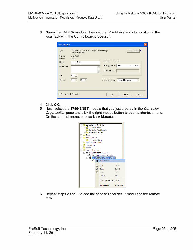
3 Name the ENBT/A module, then set the IP Address and slot location in the
local rack with the ControlLogix processor.
4 Click OK. 5 Next, select the 1756-ENBT module that you just created in the Controller
Organization pane and click the right mouse button to open a shortcut menu. On the shortcut menu, choose NEW MODULE.
6 Repeat steps 2 and 3 to add the second EtherNet/IP module to the remote rack.
Using the RSLogix 5000 v16 Add-On Instruction MVI56-MCMR ♦ ControlLogix Platform User Manual Modbus Communication Module with Reduced Data Block
Page 24 of 205 ProSoft Technology, Inc. February 11, 2011
2.3 Creating the Module - Remote Rack
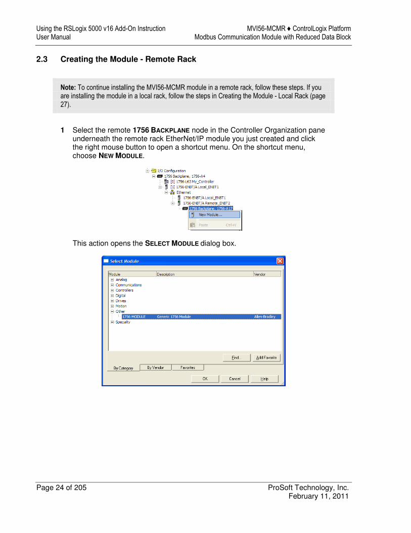
Note: To continue installing the MVI56-MCMR module in a remote rack, follow these steps. If you are installing the module in a local rack, follow the steps in Creating the Module - Local Rack (page 27).
1 Select the remote 1756 BACKPLANE node in the Controller Organization pane
underneath the remote rack EtherNet/IP module you just created and click the right mouse button to open a shortcut menu. On the shortcut menu, choose NEW MODULE.
This action opens the SELECT MODULE dialog box.
MVI56-MCMR ♦ ControlLogix Platform Using the RSLogix 5000 v16 Add-On Instruction Modbus Communication Module with Reduced Data Block User Manual
ProSoft Technology, Inc. Page 25 of 205 February 11, 2011
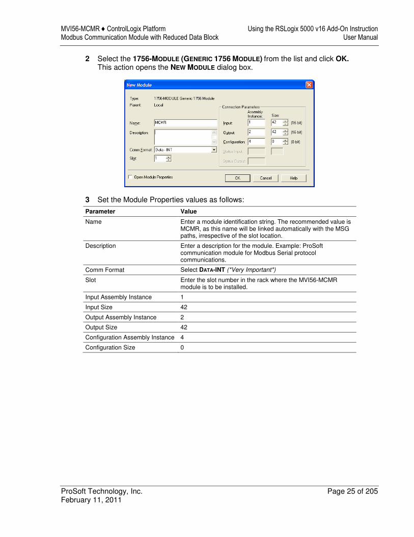
2 Select the 1756-MODULE (GENERIC 1756 MODULE) from the list and click OK. This action opens the NEW MODULE dialog box.
3 Set the Module Properties values as follows:
Parameter Value
Name Enter a module identification string. The recommended value is MCMR, as this name will be linked automatically with the MSG paths, irrespective of the slot location.
Description Enter a description for the module. Example: ProSoft communication module for Modbus Serial protocol communications.
Comm Format Select DATA-INT (*Very Important*)
Slot Enter the slot number in the rack where the MVI56-MCMR module is to be installed.
Input Assembly Instance 1
Input Size 42
Output Assembly Instance 2
Output Size 42
Configuration Assembly Instance 4
Configuration Size 0
Using the RSLogix 5000 v16 Add-On Instruction MVI56-MCMR ♦ ControlLogix Platform User Manual Modbus Communication Module with Reduced Data Block
Page 26 of 205 ProSoft Technology, Inc. February 11, 2011
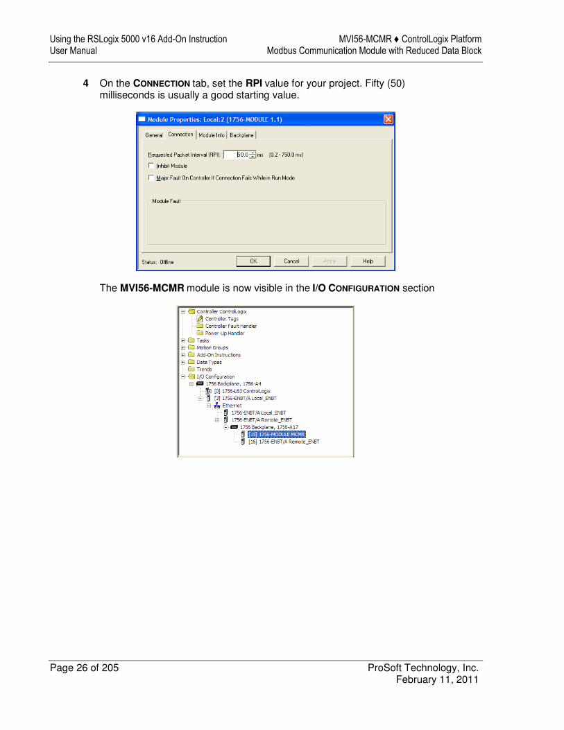
4 On the CONNECTION tab, set the RPI value for your project. Fifty (50) milliseconds is usually a good starting value.
The MVI56-MCMR module is now visible in the I/O CONFIGURATION section
MVI56-MCMR ♦ ControlLogix Platform Using the RSLogix 5000 v16 Add-On Instruction Modbus Communication Module with Reduced Data Block User Manual
ProSoft Technology, Inc. Page 27 of 205 February 11, 2011
2.4 Creating the Module
Note: If you are installing the MVI56-MCMR module in a local rack, follow these steps. If you are installing the module in a remote rack, follow the steps in Creating the Module - Remote Rack (page 22).
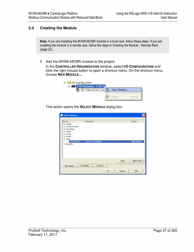
1 Add the MVI56-MCMR module to the project.
In the CONTROLLER ORGANIZATION window, select I/O CONFIGURATION and click the right mouse button to open a shortcut menu. On the shortcut menu, choose NEW MODULE...
This action opens the SELECT MODULE dialog box.
Using the RSLogix 5000 v16 Add-On Instruction MVI56-MCMR ♦ ControlLogix Platform User Manual Modbus Communication Module with Reduced Data Block
Page 28 of 205 ProSoft Technology, Inc. February 11, 2011
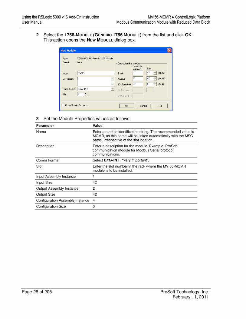
2 Select the 1756-MODULE (GENERIC 1756 MODULE) from the list and click OK. This action opens the NEW MODULE dialog box.
3 Set the Module Properties values as follows:
Parameter Value
Name Enter a module identification string. The recommended value is MCMR, as this name will be linked automatically with the MSG paths, irrespective of the slot location.
Description Enter a description for the module. Example: ProSoft communication module for Modbus Serial protocol communications.
Comm Format Select DATA-INT (*Very Important*)
Slot Enter the slot number in the rack where the MVI56-MCMR module is to be installed.
Input Assembly Instance 1
Input Size 42
Output Assembly Instance 2
Output Size 42
Configuration Assembly Instance 4
Configuration Size 0
MVI56-MCMR ♦ ControlLogix Platform Using the RSLogix 5000 v16 Add-On Instruction Modbus Communication Module with Reduced Data Block User Manual
ProSoft Technology, Inc. Page 29 of 205 February 11, 2011
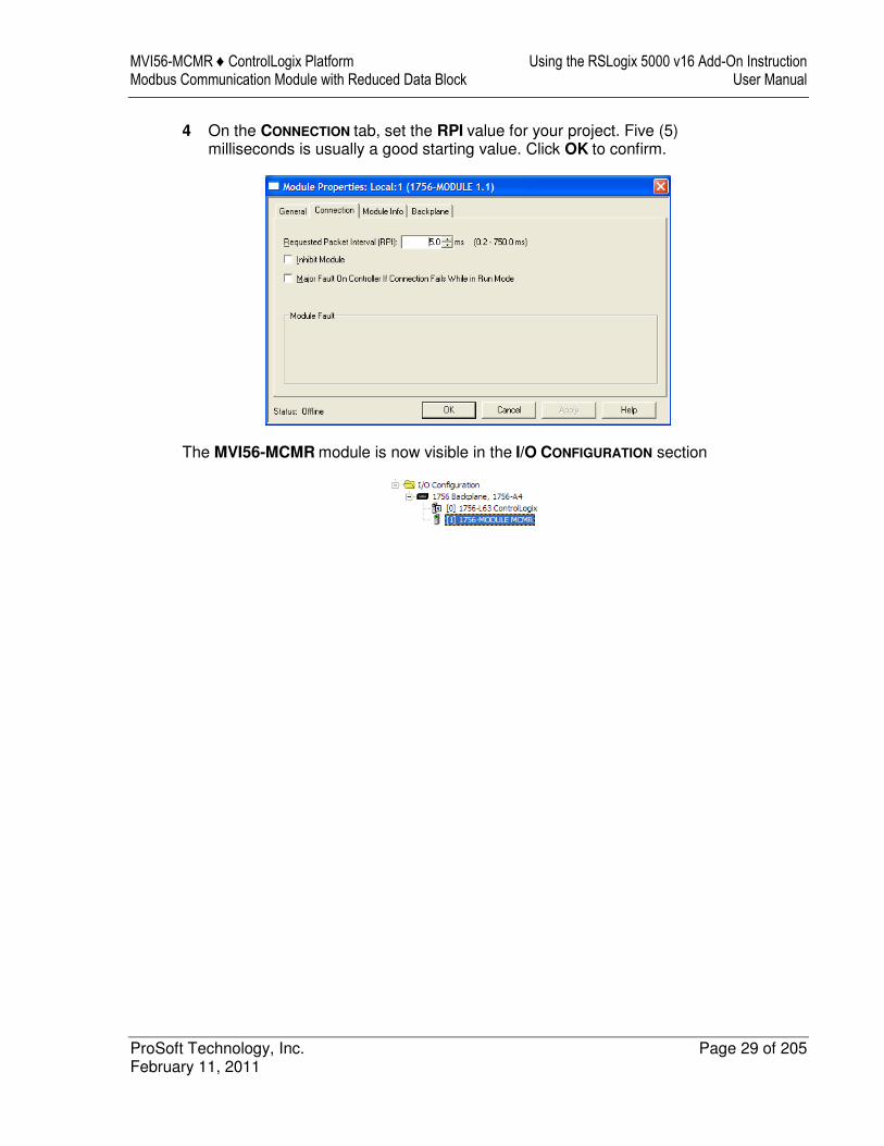
4 On the CONNECTION tab, set the RPI value for your project. Five (5) milliseconds is usually a good starting value. Click OK to confirm.
The MVI56-MCMR module is now visible in the I/O CONFIGURATION section
Using the RSLogix 5000 v16 Add-On Instruction MVI56-MCMR ♦ ControlLogix Platform User Manual Modbus Communication Module with Reduced Data Block
Page 30 of 205 ProSoft Technology, Inc. February 11, 2011
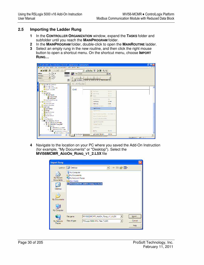
2.5 Importing the Ladder Rung
1 In the CONTROLLER ORGANIZATION window, expand the TASKS folder and subfolder until you reach the MAINPROGRAM folder.
2 In the MAINPROGRAM folder, double-click to open the MAINROUTINE ladder. 3 Select an empty rung in the new routine, and then click the right mouse
button to open a shortcut menu. On the shortcut menu, choose IMPORT
RUNG…
4 Navigate to the location on your PC where you saved the Add-On Instruction (for example, "My Documents" or "Desktop"). Select the MVI56MCMR_ADDON_RUNG_V1_2.L5X file
MVI56-MCMR ♦ ControlLogix Platform Using the RSLogix 5000 v16 Add-On Instruction Modbus Communication Module with Reduced Data Block User Manual
ProSoft Technology, Inc. Page 31 of 205 February 11, 2011
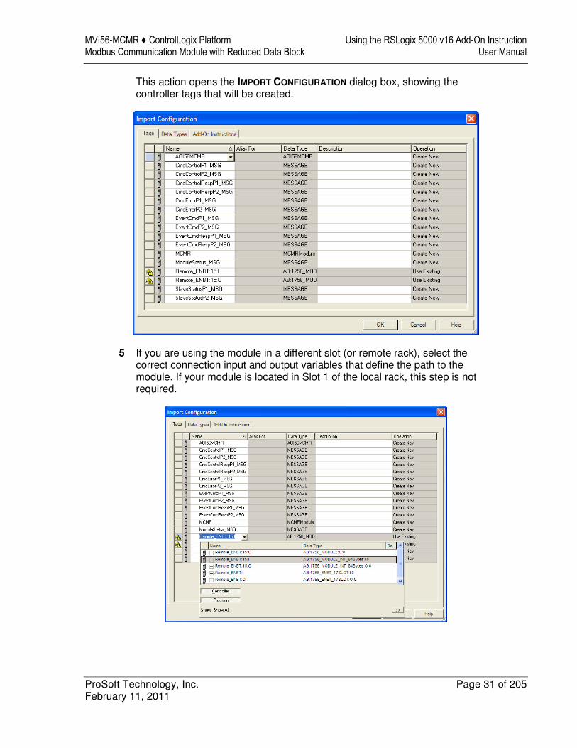
This action opens the IMPORT CONFIGURATION dialog box, showing the controller tags that will be created.
5 If you are using the module in a different slot (or remote rack), select the correct connection input and output variables that define the path to the module. If your module is located in Slot 1 of the local rack, this step is not required.
Using the RSLogix 5000 v16 Add-On Instruction MVI56-MCMR ♦ ControlLogix Platform User Manual Modbus Communication Module with Reduced Data Block
Page 32 of 205 ProSoft Technology, Inc. February 11, 2011
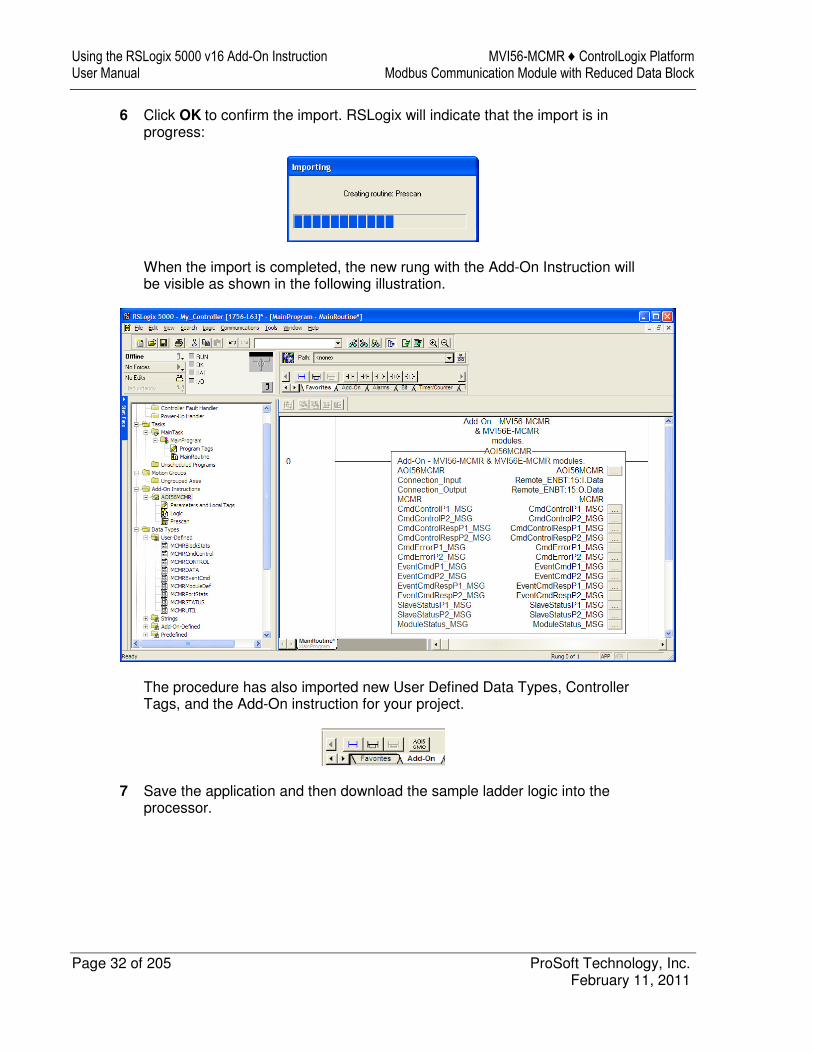
6 Click OK to confirm the import. RSLogix will indicate that the import is in progress:
When the import is completed, the new rung with the Add-On Instruction will be visible as shown in the following illustration.
The procedure has also imported new User Defined Data Types, Controller Tags, and the Add-On instruction for your project.
7 Save the application and then download the sample ladder logic into the processor.
MVI56-MCMR ♦ ControlLogix Platform Using the RSLogix 5000 v16 Add-On Instruction Modbus Communication Module with Reduced Data Block User Manual
ProSoft Technology, Inc. Page 33 of 205 February 11, 2011
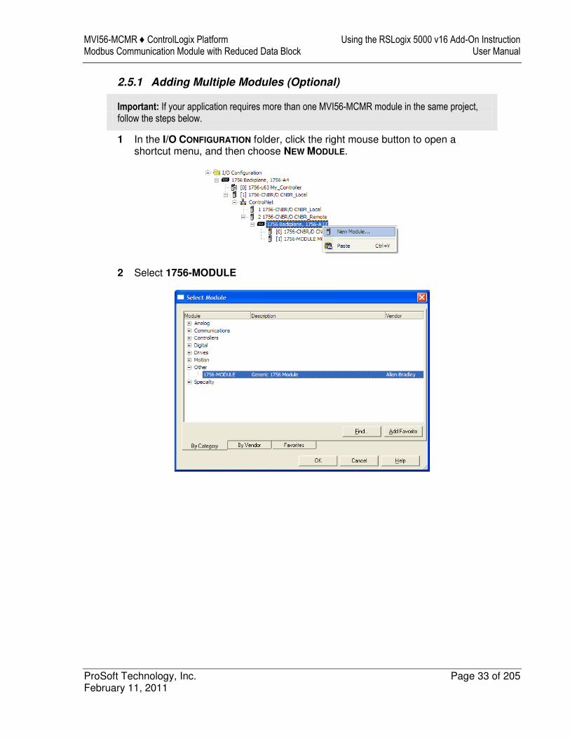
2.5.1 Adding Multiple Modules (Optional)
Important: If your application requires more than one MVI56-MCMR module in the same project, follow the steps below.
1 In the I/O CONFIGURATION folder, click the right mouse button to open a shortcut menu, and then choose NEW MODULE.
2 Select 1756-MODULE
Using the RSLogix 5000 v16 Add-On Instruction MVI56-MCMR ♦ ControlLogix Platform User Manual Modbus Communication Module with Reduced Data Block
Page 34 of 205 ProSoft Technology, Inc. February 11, 2011
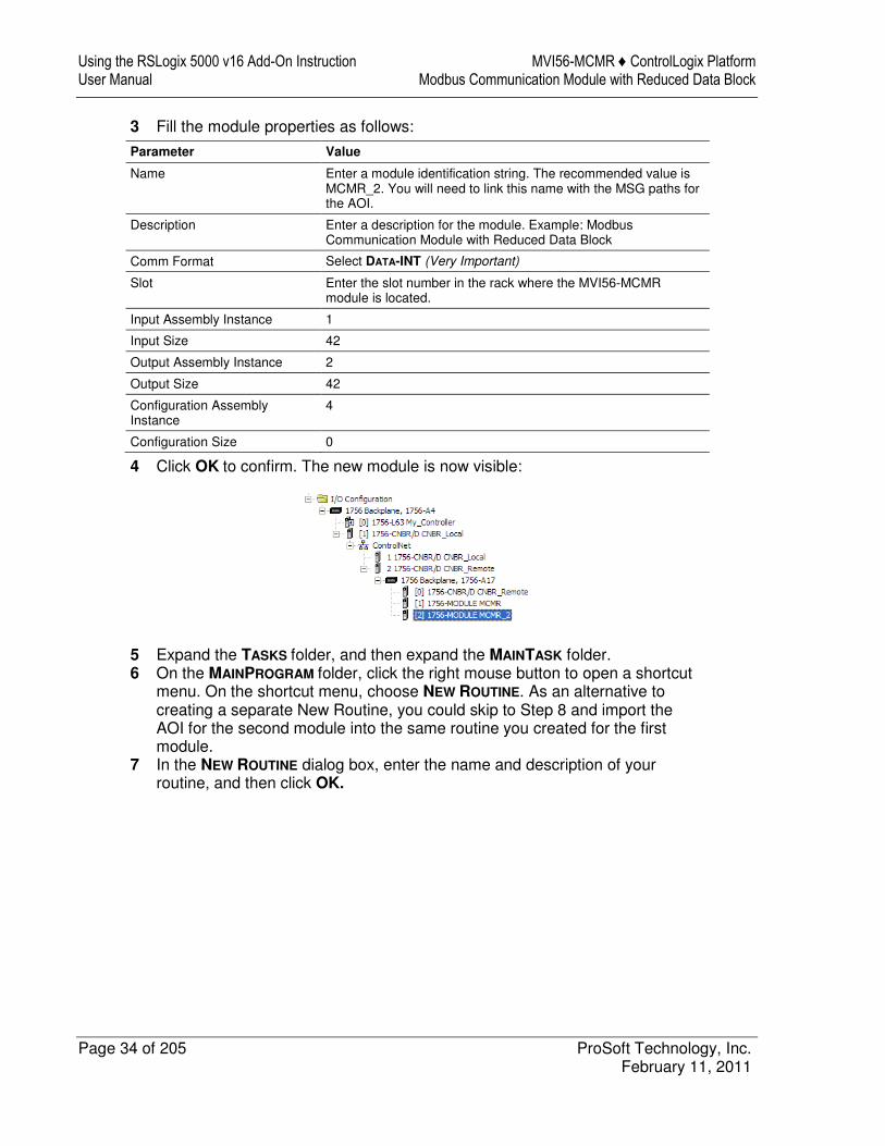
3 Fill the module properties as follows:
Parameter Value
Name Enter a module identification string. The recommended value is MCMR_2. You will need to link this name with the MSG paths for the AOI.
Description Enter a description for the module. Example: Modbus Communication Module with Reduced Data Block
Comm Format Select DATA-INT (Very Important)
Slot Enter the slot number in the rack where the MVI56-MCMR module is located.
Input Assembly Instance 1
Input Size 42
Output Assembly Instance 2
Output Size 42
Configuration Assembly Instance
4
Configuration Size 0
4 Click OK to confirm. The new module is now visible:
5 Expand the TASKS folder, and then expand the MAINTASK folder. 6 On the MAINPROGRAM folder, click the right mouse button to open a shortcut
menu. On the shortcut menu, choose NEW ROUTINE. As an alternative to creating a separate New Routine, you could skip to Step 8 and import the AOI for the second module into the same routine you created for the first module.
7 In the NEW ROUTINE dialog box, enter the name and description of your routine, and then click OK.
MVI56-MCMR ♦ ControlLogix Platform Using the RSLogix 5000 v16 Add-On Instruction Modbus Communication Module with Reduced Data Block User Manual
ProSoft Technology, Inc. Page 35 of 205 February 11, 2011
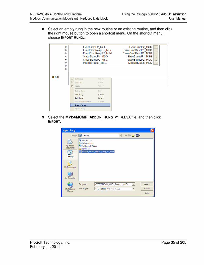
8 Select an empty rung in the new routine or an existing routine, and then click the right mouse button to open a shortcut menu. On the shortcut menu, choose IMPORT RUNG…
9 Select the MVI56MCMR_ADDON_RUNG_V1_4.L5X file, and then click IMPORT.
Using the RSLogix 5000 v16 Add-On Instruction MVI56-MCMR ♦ ControlLogix Platform User Manual Modbus Communication Module with Reduced Data Block
Page 36 of 205 ProSoft Technology, Inc. February 11, 2011
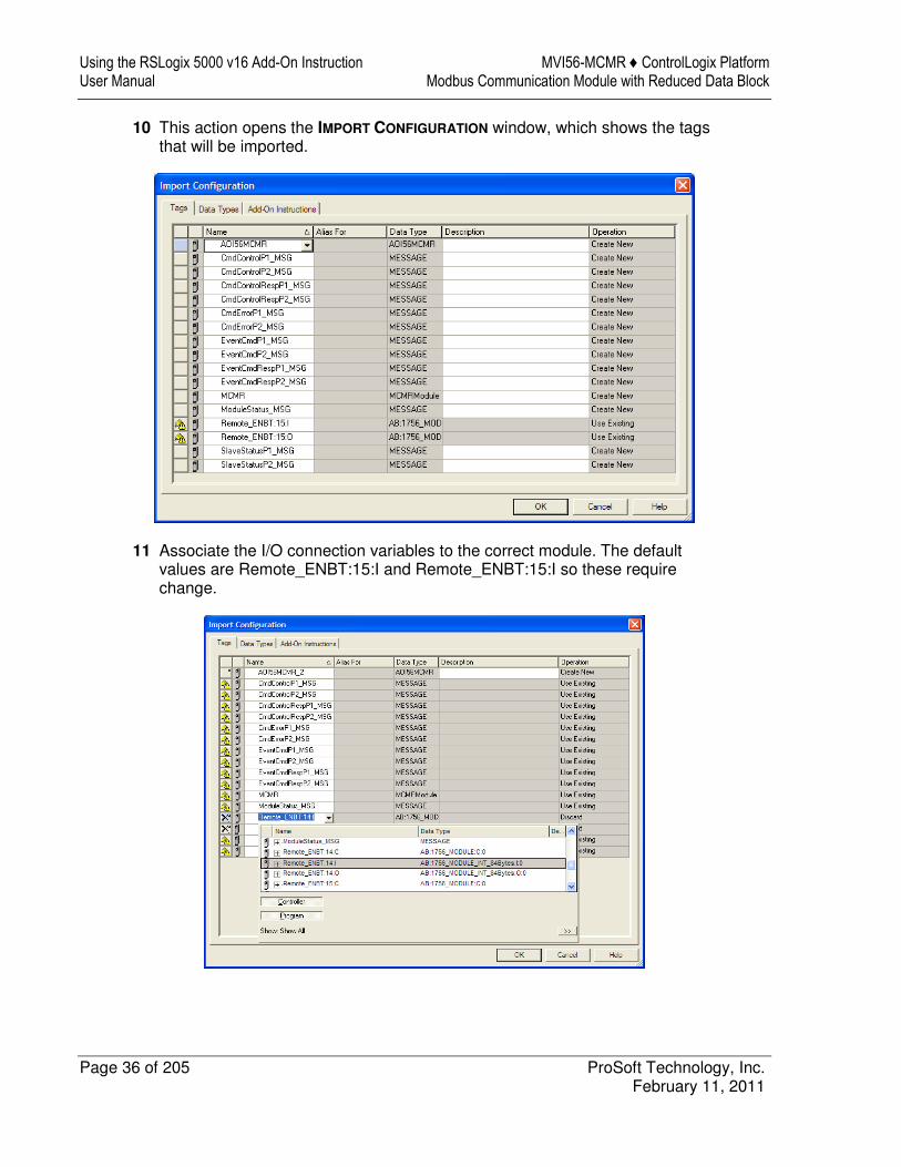
10 This action opens the IMPORT CONFIGURATION window, which shows the tags that will be imported.
11 Associate the I/O connection variables to the correct module. The default values are Remote_ENBT:15:I and Remote_ENBT:15:I so these require change.
MVI56-MCMR ♦ ControlLogix Platform Using the RSLogix 5000 v16 Add-On Instruction Modbus Communication Module with Reduced Data Block User Manual
ProSoft Technology, Inc. Page 37 of 205 February 11, 2011
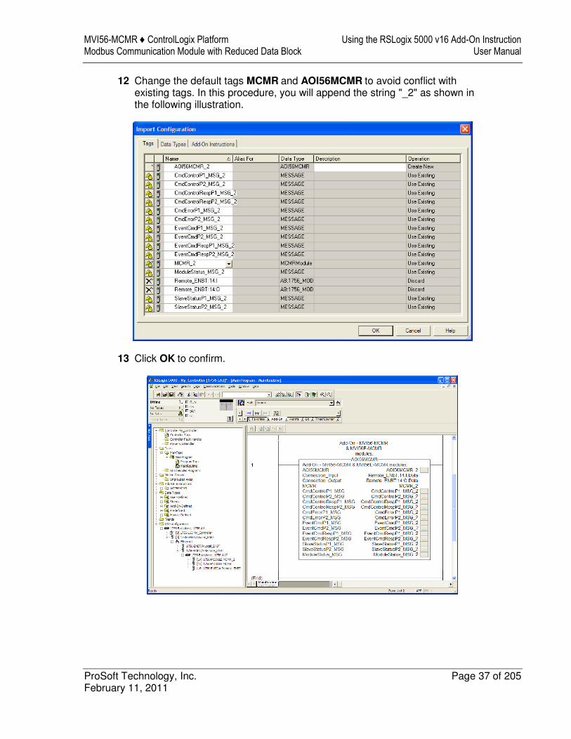
12 Change the default tags MCMR and AOI56MCMR to avoid conflict with existing tags. In this procedure, you will append the string "_2" as shown in the following illustration.
13 Click OK to confirm.
Using the RSLogix 5000 v16 Add-On Instruction MVI56-MCMR ♦ ControlLogix Platform User Manual Modbus Communication Module with Reduced Data Block
Page 38 of 205 ProSoft Technology, Inc. February 11, 2011
2.5.2 Configuring the Path for Message Blocks
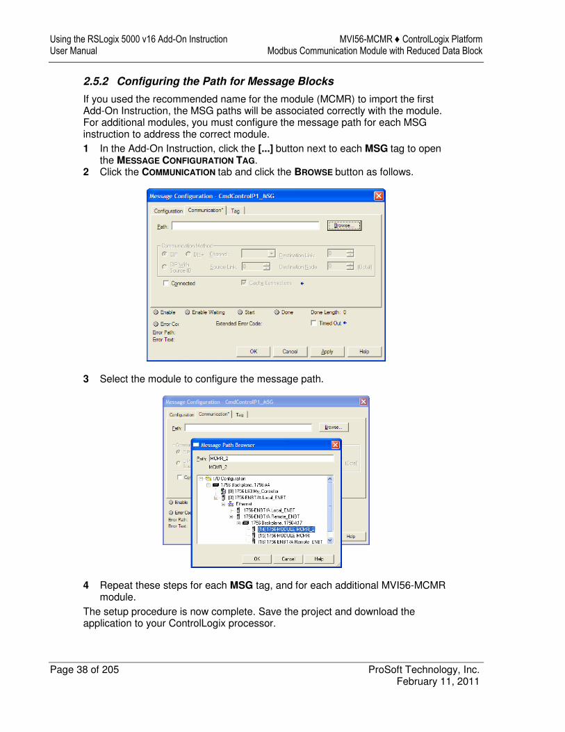
If you used the recommended name for the module (MCMR) to import the first Add-On Instruction, the MSG paths will be associated correctly with the module. For additional modules, you must configure the message path for each MSG instruction to address the correct module. 1 In the Add-On Instruction, click the [...] button next to each MSG tag to open
the MESSAGE CONFIGURATION TAG. 2 Click the COMMUNICATION tab and click the BROWSE button as follows.
3 Select the module to configure the message path.
4 Repeat these steps for each MSG tag, and for each additional MVI56-MCMR module.
The setup procedure is now complete. Save the project and download the application to your ControlLogix processor.
MVI56-MCMR ♦ ControlLogix Platform Using the RSLogix 5000 v16 Add-On Instruction Modbus Communication Module with Reduced Data Block User Manual
ProSoft Technology, Inc. Page 39 of 205 February 11, 2011
2.6 Adjusting the Input and Output Array Sizes
The module internal database is divided into two user-configurable areas: � Read Data � Write Data The Read Data area is moved from the module to the processor, while the Write Data area is moved from the processor to the module. You can configure the start register and size of each area. The size of each area you configure must match the Add-On instruction controller tag array sizes for the READDATA and WRITEDATA arrays. The MVI56-MCMR sample program is configured for 600 registers of READDATA
and 600 registers of WRITEDATA, which is sufficient for most applications. This topic describes how to configure user data for applications requiring more than 600 registers of ReadData and WriteData.
Important: Because the module pages data in blocks of 40 registers at a time, you must configure your user data in multiples of 40 registers. Caution: When you change the array size, RSLogix may reset the MCMR tag values to zero. To avoid data loss, be sure to save your settings before continuing.
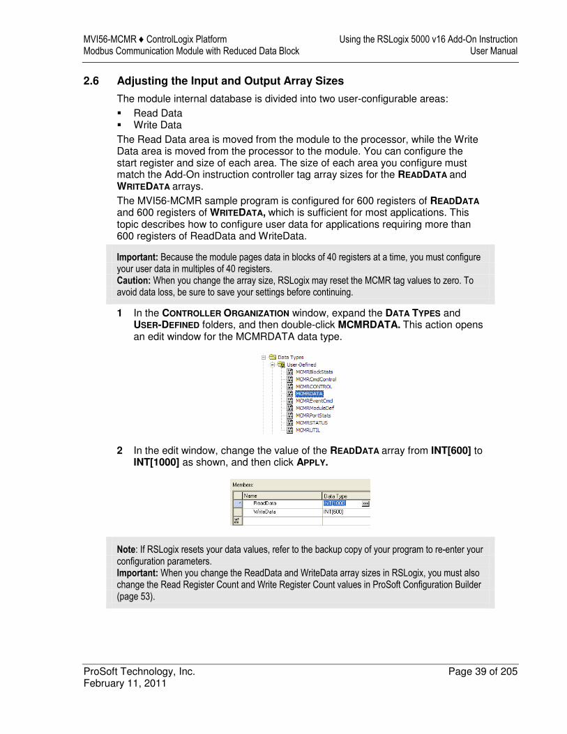
1 In the CONTROLLER ORGANIZATION window, expand the DATA TYPES and USER-DEFINED folders, and then double-click MCMRDATA. This action opens an edit window for the MCMRDATA data type.
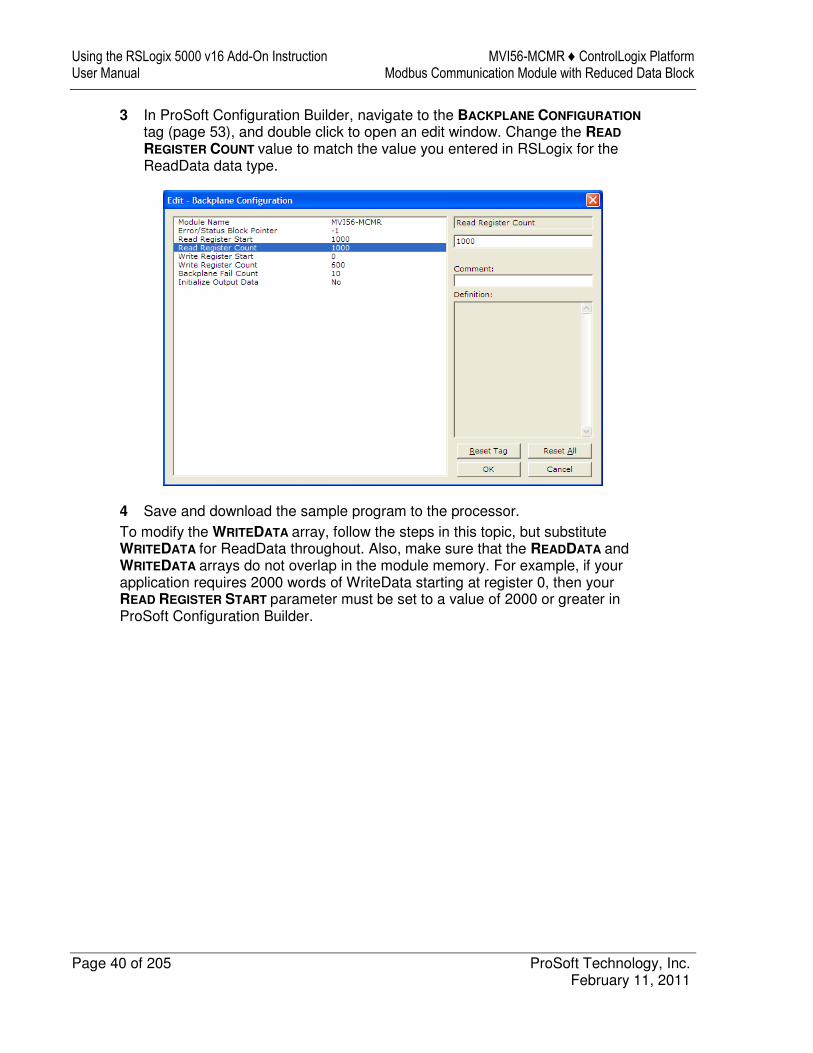
2 In the edit window, change the value of the READDATA array from INT[600] to INT[1000] as shown, and then click APPLY.
Note: If RSLogix resets your data values, refer to the backup copy of your program to re-enter your configuration parameters. Important: When you change the ReadData and WriteData array sizes in RSLogix, you must also change the Read Register Count and Write Register Count values in ProSoft Configuration Builder (page 53).
Using the RSLogix 5000 v16 Add-On Instruction MVI56-MCMR ♦ ControlLogix Platform User Manual Modbus Communication Module with Reduced Data Block
Page 40 of 205 ProSoft Technology, Inc. February 11, 2011
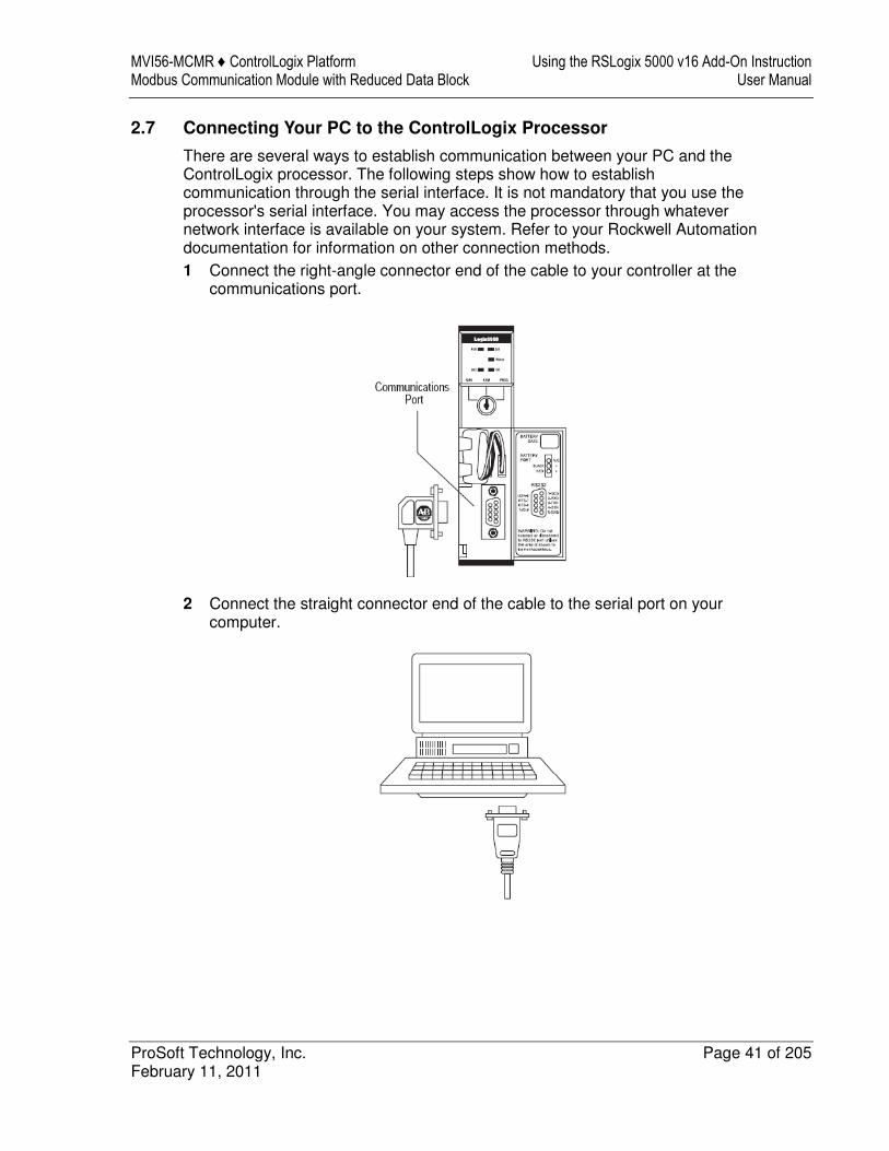
3 In ProSoft Configuration Builder, navigate to the BACKPLANE CONFIGURATION tag (page 53), and double click to open an edit window. Change the READ
REGISTER COUNT value to match the value you entered in RSLogix for the ReadData data type.
4 Save and download the sample program to the processor. To modify the WRITEDATA array, follow the steps in this topic, but substitute WRITEDATA for ReadData throughout. Also, make sure that the READDATA and WRITEDATA arrays do not overlap in the module memory. For example, if your application requires 2000 words of WriteData starting at register 0, then your READ REGISTER START parameter must be set to a value of 2000 or greater in ProSoft Configuration Builder.
MVI56-MCMR ♦ ControlLogix Platform Using the RSLogix 5000 v16 Add-On Instruction Modbus Communication Module with Reduced Data Block User Manual
ProSoft Technology, Inc. Page 41 of 205 February 11, 2011
2.7 Connecting Your PC to the ControlLogix Processor
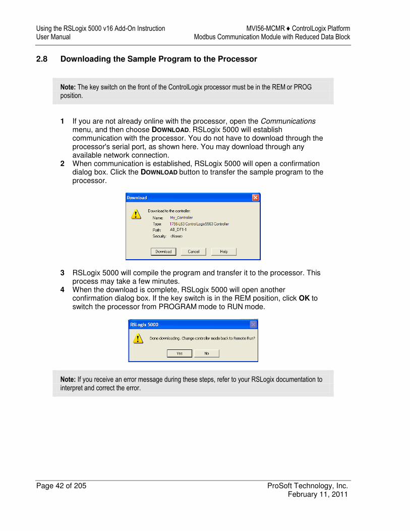
There are several ways to establish communication between your PC and the ControlLogix processor. The following steps show how to establish communication through the serial interface. It is not mandatory that you use the processor's serial interface. You may access the processor through whatever network interface is available on your system. Refer to your Rockwell Automation documentation for information on other connection methods. 1 Connect the right-angle connector end of the cable to your controller at the
communications port.
2 Connect the straight connector end of the cable to the serial port on your computer.
Using the RSLogix 5000 v16 Add-On Instruction MVI56-MCMR ♦ ControlLogix Platform User Manual Modbus Communication Module with Reduced Data Block
Page 42 of 205 ProSoft Technology, Inc. February 11, 2011
2.8 Downloading the Sample Program to the Processor
Note: The key switch on the front of the ControlLogix processor must be in the REM or PROG
position.
1 If you are not already online with the processor, open the Communications
menu, and then choose DOWNLOAD. RSLogix 5000 will establish communication with the processor. You do not have to download through the processor's serial port, as shown here. You may download through any available network connection.
2 When communication is established, RSLogix 5000 will open a confirmation dialog box. Click the DOWNLOAD button to transfer the sample program to the processor.
3 RSLogix 5000 will compile the program and transfer it to the processor. This process may take a few minutes.
4 When the download is complete, RSLogix 5000 will open another confirmation dialog box. If the key switch is in the REM position, click OK to switch the processor from PROGRAM mode to RUN mode.
Note: If you receive an error message during these steps, refer to your RSLogix documentation to interpret and correct the error.
MVI56-MCMR ♦ ControlLogix Platform Using the RSLogix 5000 v16 Add-On Instruction Modbus Communication Module with Reduced Data Block User Manual
ProSoft Technology, Inc. Page 43 of 205 February 11, 2011
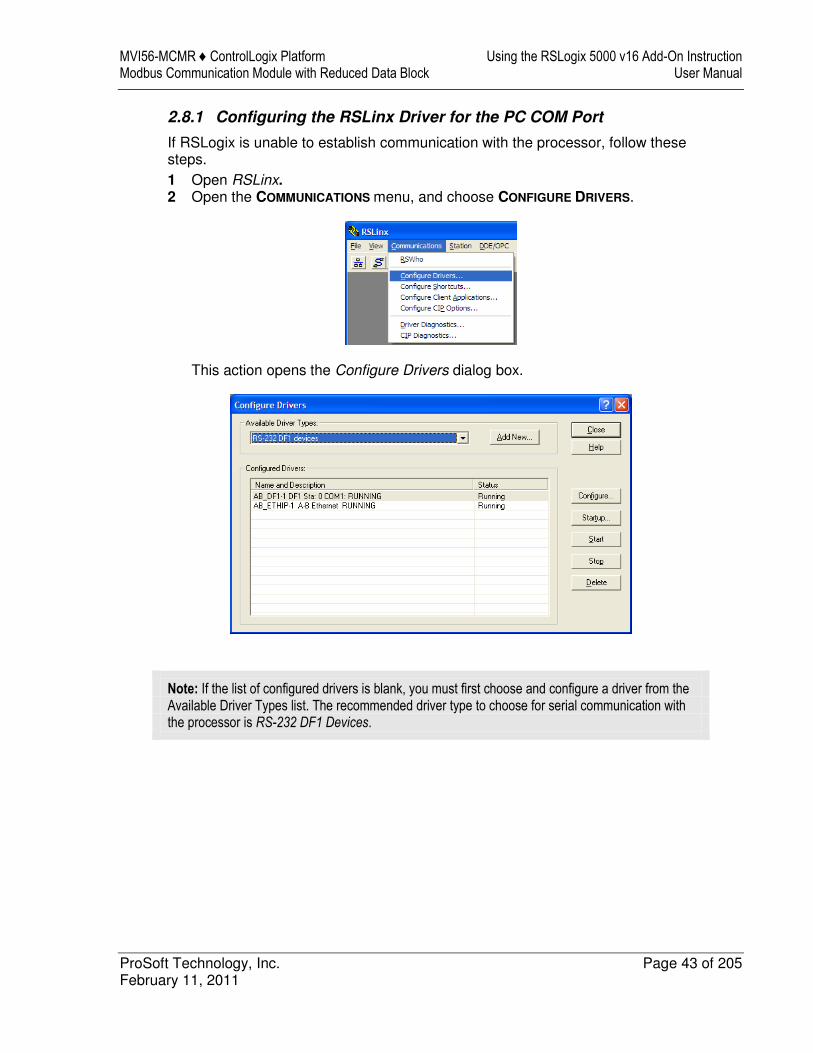
2.8.1 Configuring the RSLinx Driver for the PC COM Port
If RSLogix is unable to establish communication with the processor, follow these steps. 1 Open RSLinx. 2 Open the COMMUNICATIONS menu, and choose CONFIGURE DRIVERS.
This action opens the Configure Drivers dialog box.
Note: If the list of configured drivers is blank, you must first choose and configure a driver from the Available Driver Types list. The recommended driver type to choose for serial communication with the processor is RS-232 DF1 Devices.
Using the RSLogix 5000 v16 Add-On Instruction MVI56-MCMR ♦ ControlLogix Platform User Manual Modbus Communication Module with Reduced Data Block
Page 44 of 205 ProSoft Technology, Inc. February 11, 2011
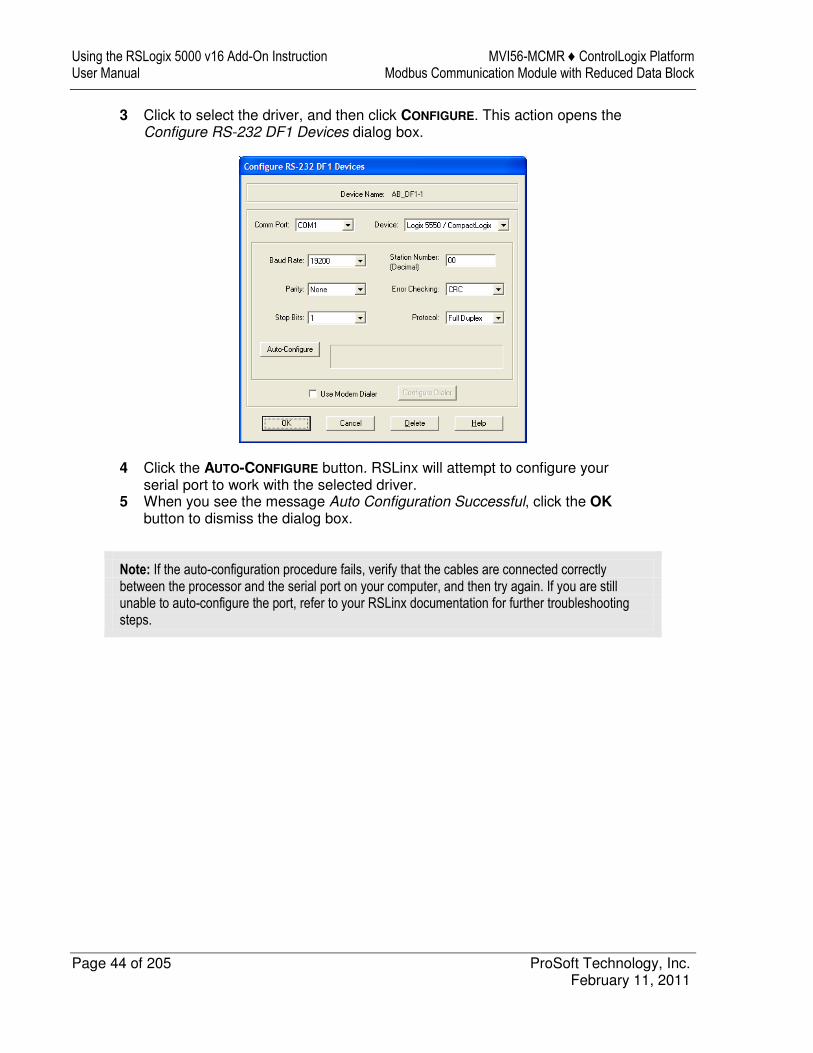
3 Click to select the driver, and then click CONFIGURE. This action opens the Configure RS-232 DF1 Devices dialog box.
4 Click the AUTO-CONFIGURE button. RSLinx will attempt to configure your serial port to work with the selected driver.
5 When you see the message Auto Configuration Successful, click the OK
button to dismiss the dialog box.
Note: If the auto-configuration procedure fails, verify that the cables are connected correctly between the processor and the serial port on your computer, and then try again. If you are still unable to auto-configure the port, refer to your RSLinx documentation for further troubleshooting steps.
MVI56-MCMR ♦ ControlLogix Platform Configuring the MVI56-MCMR Module Modbus Communication Module with Reduced Data Block User Manual
ProSoft Technology, Inc. Page 45 of 205 February 11, 2011
3 Configuring the MVI56-MCMR Module
In This Chapter
� Using ProSoft Configuration Builder ...................................................... 46
� Downloading the Project to the Module Using a Serial COM port ......... 50
Configuring the MVI56-MCMR Module MVI56-MCMR ♦ ControlLogix Platform User Manual Modbus Communication Module with Reduced Data Block
Page 46 of 205 ProSoft Technology, Inc. February 11, 2011
3.1 Using ProSoft Configuration Builder
ProSoft Configuration Builder (PCB) provides a quick and easy way to manage gateway configuration files customized to meet your application needs. PCB is not only a powerful solution for new configuration files, but also allows you to import information from previously installed (known working) configurations to new projects.
3.1.1 Setting Up the Project
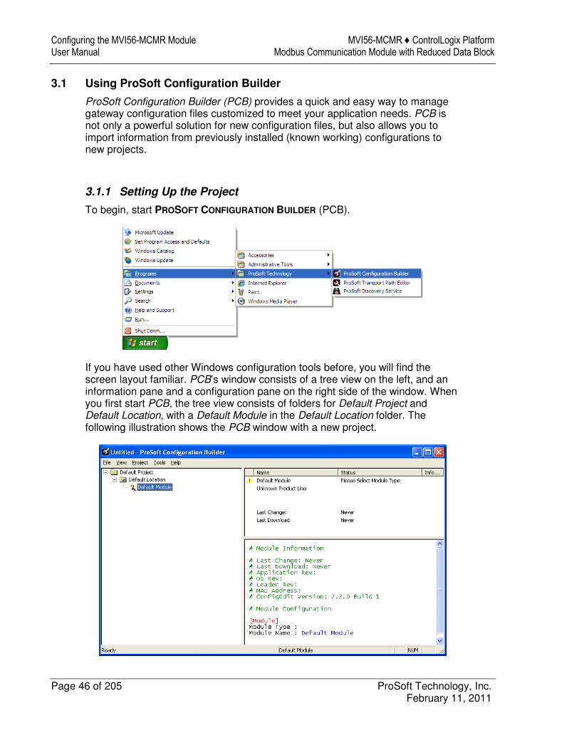
To begin, start PROSOFT CONFIGURATION BUILDER (PCB).
If you have used other Windows configuration tools before, you will find the screen layout familiar. PCB’s window consists of a tree view on the left, and an information pane and a configuration pane on the right side of the window. When you first start PCB, the tree view consists of folders for Default Project and Default Location, with a Default Module in the Default Location folder. The following illustration shows the PCB window with a new project.
MVI56-MCMR ♦ ControlLogix Platform Configuring the MVI56-MCMR Module Modbus Communication Module with Reduced Data Block User Manual
ProSoft Technology, Inc. Page 47 of 205 February 11, 2011
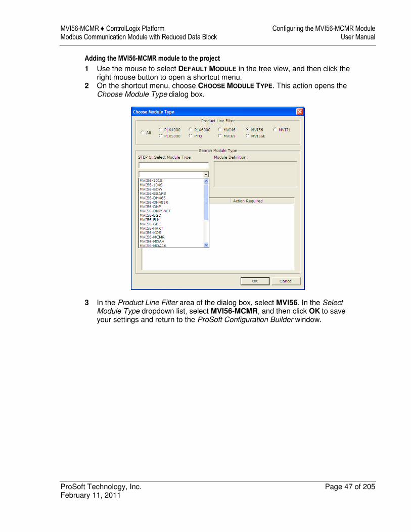
Adding the MVI56-MCMR module to the project
1 Use the mouse to select DEFAULT MODULE in the tree view, and then click the right mouse button to open a shortcut menu.
2 On the shortcut menu, choose CHOOSE MODULE TYPE. This action opens the
Choose Module Type dialog box.
3 In the Product Line Filter area of the dialog box, select MVI56. In the Select Module Type dropdown list, select MVI56-MCMR, and then click OK to save your settings and return to the ProSoft Configuration Builder window.
Configuring the MVI56-MCMR Module MVI56-MCMR ♦ ControlLogix Platform User Manual Modbus Communication Module with Reduced Data Block
Page 48 of 205 ProSoft Technology, Inc. February 11, 2011
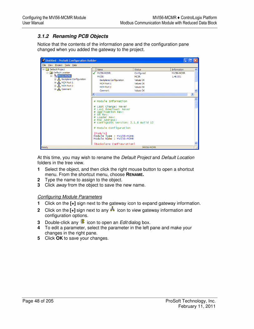
3.1.2 Renaming PCB Objects
Notice that the contents of the information pane and the configuration pane changed when you added the gateway to the project.
At this time, you may wish to rename the Default Project and Default Location folders in the tree view. 1 Select the object, and then click the right mouse button to open a shortcut
menu. From the shortcut menu, choose RENAME. 2 Type the name to assign to the object. 3 Click away from the object to save the new name.
Configuring Module Parameters
1 Click on the [+] sign next to the gateway icon to expand gateway information.
2 Click on the [+] sign next to any icon to view gateway information and configuration options.
3 Double-click any icon to open an Edit dialog box. 4 To edit a parameter, select the parameter in the left pane and make your
changes in the right pane. 5 Click OK to save your changes.
MVI56-MCMR ♦ ControlLogix Platform Configuring the MVI56-MCMR Module Modbus Communication Module with Reduced Data Block User Manual
ProSoft Technology, Inc. Page 49 of 205 February 11, 2011
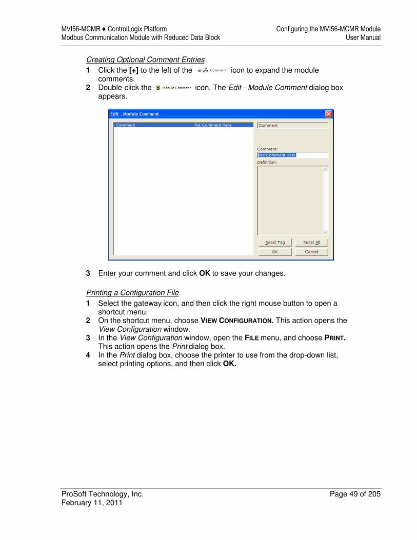
Creating Optional Comment Entries
1 Click the [+] to the left of the icon to expand the module comments.
2 Double-click the icon. The Edit - Module Comment dialog box appears.
3 Enter your comment and click OK to save your changes.
Printing a Configuration File
1 Select the gateway icon, and then click the right mouse button to open a shortcut menu.
2 On the shortcut menu, choose VIEW CONFIGURATION. This action opens the View Configuration window.
3 In the View Configuration window, open the FILE menu, and choose PRINT. This action opens the Print dialog box.
4 In the Print dialog box, choose the printer to use from the drop-down list, select printing options, and then click OK.
Configuring the MVI56-MCMR Module MVI56-MCMR ♦ ControlLogix Platform User Manual Modbus Communication Module with Reduced Data Block
Page 50 of 205 ProSoft Technology, Inc. February 11, 2011
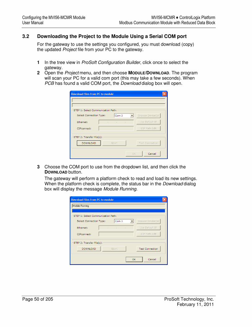
3.2 Downloading the Project to the Module Using a Serial COM port
For the gateway to use the settings you configured, you must download (copy) the updated Project file from your PC to the gateway. 1 In the tree view in ProSoft Configuration Builder, click once to select the
gateway. 2 Open the Project menu, and then choose MODULE/DOWNLOAD. The program
will scan your PC for a valid com port (this may take a few seconds). When PCB has found a valid COM port, the Download dialog box will open.
3 Choose the COM port to use from the dropdown list, and then click the DOWNLOAD button. The gateway will perform a platform check to read and load its new settings. When the platform check is complete, the status bar in the Download dialog box will display the message Module Running.
MVI56-MCMR ♦ ControlLogix Platform Configuration as a Modbus Master Modbus Communication Module with Reduced Data Block User Manual
ProSoft Technology, Inc. Page 51 of 205 February 11, 2011
4 Configuration as a Modbus Master
In This Chapter
� Overview ............................................................................................... 52
� Backplane Configuration ....................................................................... 53
� Port Configuration ................................................................................. 55
� Master Command Configuration ............................................................ 57
� Other Modbus Addressing Schemes ..................................................... 61
� Master Command Examples ................................................................. 63
� Floating-Point Data Handling (Modbus Master) ..................................... 71
Configuration as a Modbus Master MVI56-MCMR ♦ ControlLogix Platform User Manual Modbus Communication Module with Reduced Data Block
Page 52 of 205 ProSoft Technology, Inc. February 11, 2011
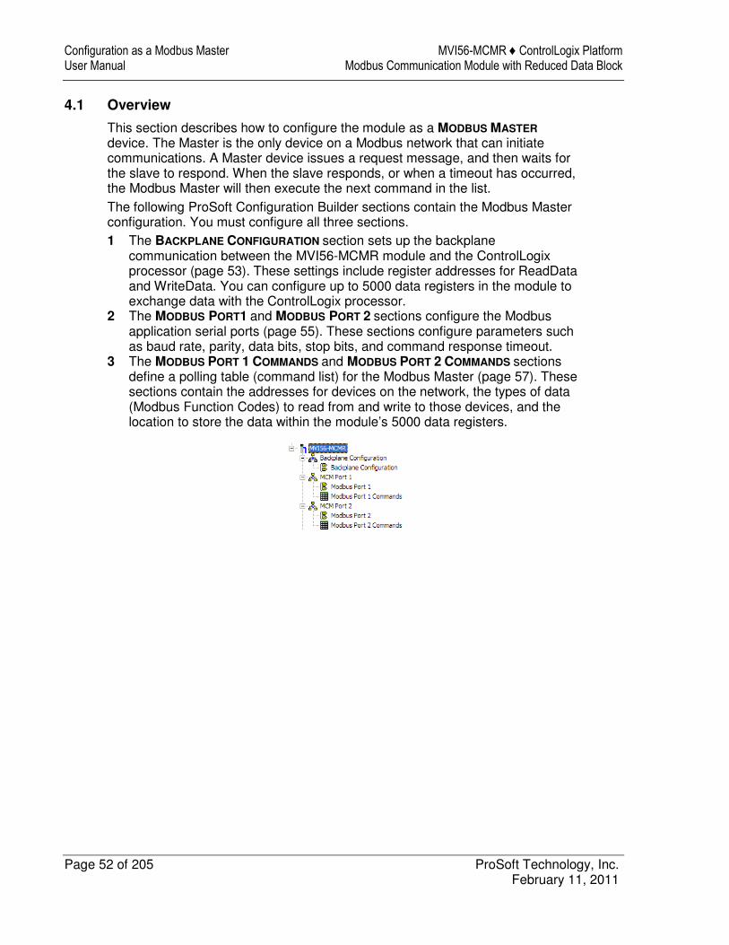
4.1 Overview
This section describes how to configure the module as a MODBUS MASTER device. The Master is the only device on a Modbus network that can initiate communications. A Master device issues a request message, and then waits for the slave to respond. When the slave responds, or when a timeout has occurred, the Modbus Master will then execute the next command in the list. The following ProSoft Configuration Builder sections contain the Modbus Master configuration. You must configure all three sections. 1 The BACKPLANE CONFIGURATION section sets up the backplane
communication between the MVI56-MCMR module and the ControlLogix processor (page 53). These settings include register addresses for ReadData and WriteData. You can configure up to 5000 data registers in the module to exchange data with the ControlLogix processor.
2 The MODBUS PORT1 and MODBUS PORT 2 sections configure the Modbus application serial ports (page 55). These sections configure parameters such as baud rate, parity, data bits, stop bits, and command response timeout.
3 The MODBUS PORT 1 COMMANDS and MODBUS PORT 2 COMMANDS sections define a polling table (command list) for the Modbus Master (page 57). These sections contain the addresses for devices on the network, the types of data (Modbus Function Codes) to read from and write to those devices, and the location to store the data within the module’s 5000 data registers.
MVI56-MCMR ♦ ControlLogix Platform Configuration as a Modbus Master Modbus Communication Module with Reduced Data Block User Manual
ProSoft Technology, Inc. Page 53 of 205 February 11, 2011
4.2 Backplane Configuration
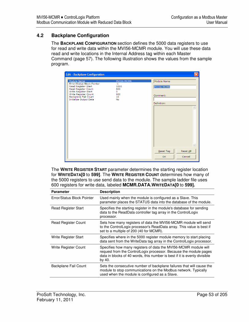
The BACKPLANE CONFIGURATION section defines the 5000 data registers to use for read and write data within the MVI56-MCMR module. You will use these data read and write locations in the Internal Address tag within each Master Command (page 57). The following illustration shows the values from the sample program.
The WRITE REGISTER START parameter determines the starting register location for WRITEDATA[0 to 599]. The WRITE REGISTER COUNT determines how many of the 5000 registers to use send data to the module. The sample ladder file uses 600 registers for write data, labeled MCMR.DATA.WRITEDATA[0 to 599].
Parameter Description
Error/Status Block Pointer Used mainly when the module is configured as a Slave. This parameter places the STATUS data into the database of the module.
Read Register Start Specifies the starting register in the module's database for sending data to the ReadData controller tag array in the ControlLogix processor.
Read Register Count Sets how many registers of data the MVI56-MCMR module will send to the ControlLogix processor's ReadData array. This value is best if set to a multiple of 200 (40 for MCMR).
Write Register Start Specifies where in the 5000 register module memory to start placing data sent from the WriteData tag array in the ControlLogix processor.
Write Register Count Specifies how many registers of data the MVI56-MCMR module will request from the ControlLogix processor. Because the module pages data in blocks of 40 words, this number is best if it is evenly divisible by 40.
Backplane Fail Count Sets the consecutive number of backplane failures that will cause the module to stop communications on the Modbus network. Typically used when the module is configured as a Slave.
Configuration as a Modbus Master MVI56-MCMR ♦ ControlLogix Platform User Manual Modbus Communication Module with Reduced Data Block
Page 54 of 205 ProSoft Technology, Inc. February 11, 2011
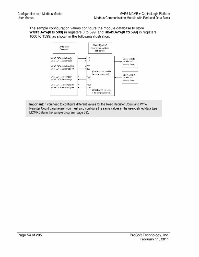
The sample configuration values configure the module database to store WRITEDATA[0 to 599] in registers 0 to 599, and READDATA[0 TO 599] in registers 1000 to 1599, as shown in the following illustration.
Important: If you need to configure different values for the Read Register Count and Write Register Count parameters, you must also configure the same values in the user-defined data type MCMRData in the sample program (page 39).
MVI56-MCMR ♦ ControlLogix Platform Configuration as a Modbus Master Modbus Communication Module with Reduced Data Block User Manual
ProSoft Technology, Inc. Page 55 of 205 February 11, 2011
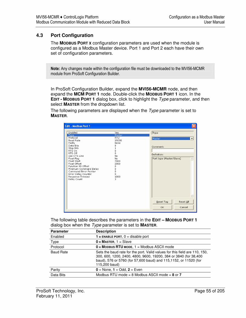
4.3 Port Configuration
The MODBUS PORT X configuration parameters are used when the module is configured as a Modbus Master device. Port 1 and Port 2 each have their own set of configuration parameters.
Note: Any changes made within the configuration file must be downloaded to the MVI56-MCMR module from ProSoft Configuration Builder.
In ProSoft Configuration Builder, expand the MVI56-MCMR node, and then expand the MCM PORT 1 node. Double-click the MODBUS PORT 1 icon. In the EDIT - MODBUS PORT 1 dialog box, click to highlight the Type parameter, and then select MASTER from the dropdown list. The following parameters are displayed when the Type parameter is set to MASTER.
The following table describes the parameters in the EDIT – MODBUS PORT 1 dialog box when the Type parameter is set to MASTER. Parameter Description
Enabled 1 = ENABLE PORT, 0 = disable port
Type 0 = MASTER, 1 = Slave
Protocol 0 = MODBUS RTU MODE, 1 = Modbus ASCII mode
Baud Rate Sets the baud rate for the port. Valid values for this field are 110, 150, 300, 600, 1200, 2400, 4800, 9600, 19200, 384 or 3840 (for 38,400 baud), 576 or 5760 (for 57,600 baud) and 115,1152, or 11520 (for 115,200 baud)
Parity 0 = None, 1 = Odd, 2 = Even
Data Bits Modbus RTU mode = 8 Modbus ASCII mode = 8 or 7
Configuration as a Modbus Master MVI56-MCMR ♦ ControlLogix Platform User Manual Modbus Communication Module with Reduced Data Block
Page 56 of 205 ProSoft Technology, Inc. February 11, 2011
Parameter Description
Stop Bits Valid values are 1 or 2.
RTS On 0 to 65535 milliseconds to delay after RTS line is asserted on the port before data message transmission begins. This delay can be used to allow for radio keying or modem dialing before data transmission begins.
RTS Off 0 to 65535 milliseconds to delay after data message is complete before RTS line is dropped on the port.
Use CTS Line NO or YES This parameter is used to enable or disable hardware handshaking. The default setting is NO hardware handshaking, CTS Line not used. Set to NO if the connected devices do not need hardware handshaking. Set to YES if the device(s) connected to the port require hardware handshaking (most modern devices do not). If you set this parameter to YES, be sure to pay attention to the pinout and wiring requirements to ensure that the hardware handshaking signal lines are properly connected; otherwise communication will fail.
Float Flag YES or NO Enables or disables use of floating data type
Float Start 0 to 32767 Register offset in message for floats
Float Offset 0 to 3998 Internal address for floats
Function 99 Offset 1 to 247 Modbus node address for this port on the network
Minimum Command Delay 0-65535 milliseconds The amount of delay in milliseconds to be inserted after receiving a Slave response or encountering a response timeout before retrying the command or sending the next command on the list. Use this parameter to slow down overall polling speed and spread out commands on networks with Slaves that require additional gaps between messages.
Command Error Pointer Internal DB location to place command error list Each command will reserve one word for the command error code for that command. See Verify Communication (page 91). CMDERRPTR
value should be within the range of the READDATA array. See Backplane Configuration (page 53).
Error Delay Counter This parameter specifies the number of poll attempts to be skipped before trying to re-establish communications with a slave that has failed to respond to a command within the time limit set by the Response Timeout parameter. After the slave fails to respond, the master will skip sending commands that should have been sent to the slave until the number of skipped commands matches the value entered in this parameter. This creates a sort of slow poll mode for slaves that are experiencing communication problems.
Response Timeout 0 to 65535 milliseconds response timeout for command before it will either reissue the command, if RETRYCOUNT > 0. If the RetryCount =0 or if the designated number of retries have been accomplished, then the Master will move on to the next command in the list.
Retry Count Number of times to retry a failed command request before moving to the next command on the list.
MVI56-MCMR ♦ ControlLogix Platform Configuration as a Modbus Master Modbus Communication Module with Reduced Data Block User Manual
ProSoft Technology, Inc. Page 57 of 205 February 11, 2011
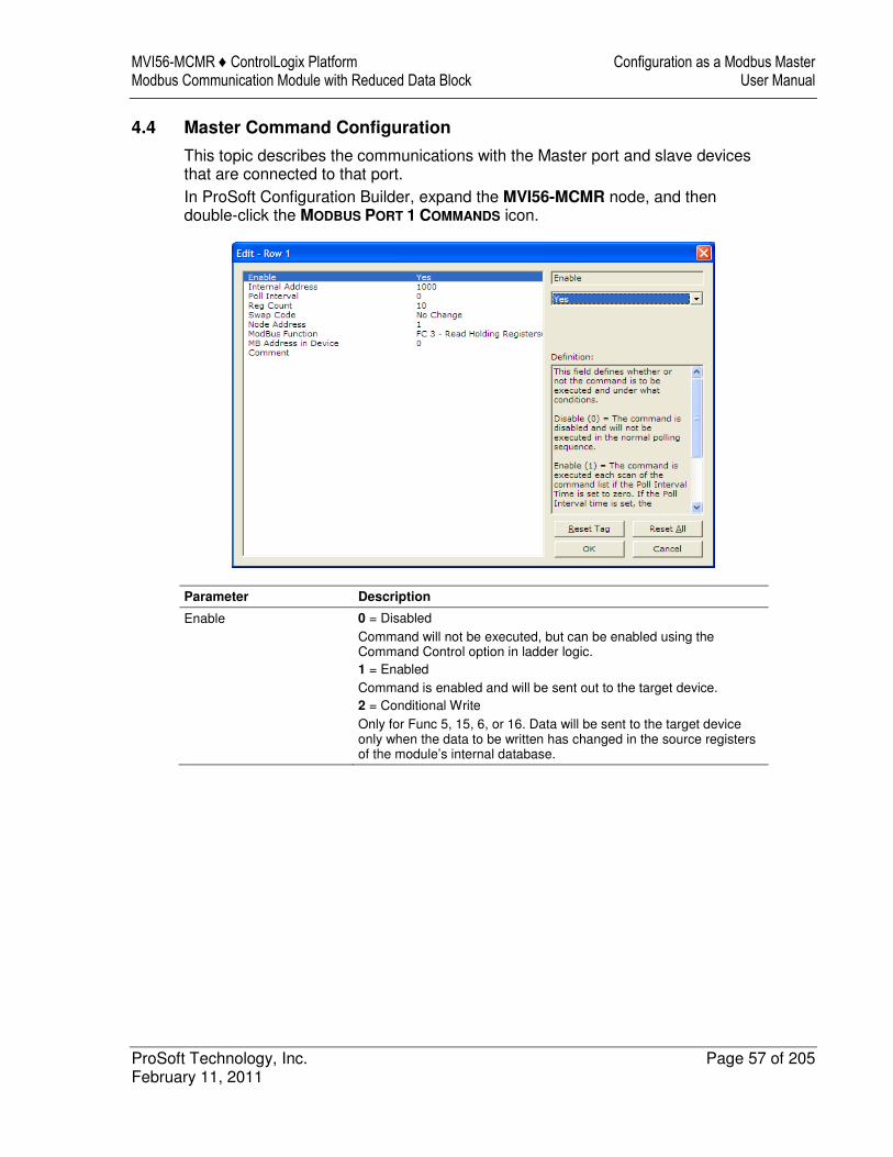
4.4 Master Command Configuration
This topic describes the communications with the Master port and slave devices that are connected to that port. In ProSoft Configuration Builder, expand the MVI56-MCMR node, and then double-click the MODBUS PORT 1 COMMANDS icon.
Parameter Description
Enable 0 = Disabled Command will not be executed, but can be enabled using the Command Control option in ladder logic. 1 = Enabled Command is enabled and will be sent out to the target device. 2 = Conditional Write Only for Func 5, 15, 6, or 16. Data will be sent to the target device only when the data to be written has changed in the source registers of the module’s internal database.
Configuration as a Modbus Master MVI56-MCMR ♦ ControlLogix Platform User Manual Modbus Communication Module with Reduced Data Block
Page 58 of 205 ProSoft Technology, Inc. February 11, 2011
Parameter Description
Internal Address 0 to 4999 for Register-level commands 0 to 65535 for Bit-level commands Determines the starting address in the module’s 5000-register database that will be affected by the command. For a Read command, this will determine where the data will begin to be placed in the module database after it has been read from a slave. For read commands, you should configure this value so that the data will be placed in the range of module memory designated for ReadData, as defined in the Backplane Configuration section of this configuration file. For write commands, the INTERNAL ADDRESS determines where to begin obtaining the data to write to the slave device. This must be a location that is in the WriteData area of module memory, as defined in the Backplane Configuration section of this configuration file. Note: When using a bit-level command, you must define this field at the bit level. For example, when using a Function Code 1, 2 for a Read command, you must have a value of 16000 to place the data in MCM.ReadData[0] (ReadStartRegister = 1000 * 16 bits per register = 16000).
Poll Interval 0 to 65535 The Poll Interval is the number of seconds that the Master will wait between successive executions of this command. Set to zero (0) for the fastest possible polling. This parameter can be used to prioritize and optimize network traffic by assigning low values to high-priority poll requests and assigning higher values to less important data poll commands.
Reg Count 1 to 125 words for Function Codes 3, 4, and 16 (Register-level) 1 to 2000 for Function Codes 1, 2, and 15 (Bit-level) Sets how many continuous words (Function Codes 3, 4, and 16) or bits (Function Codes 1, 2, and 15) to request from the slave device. Note: These values are the maximum allowed in the Modbus protocol. Some devices may support fewer words or bits per command than these maximum values.
Swap Code NO CHANGE, SWAP WORDS, SWAP WORDS & BYTES, SWAP BYTES Typically used when reading floating-point data. Swaps the data read from the slave device before it is placed into the module memory. For example, you receive 4 bytes of data from the slave (ABCD). NO CHANGE = No swapping (ABCD) SWAP WORDS = Word pairs switched (CDAB) SWAP WORDS AND BYTES = Bytes and words switched (DCBA) SWAP BYTES = Bytes swapped (BADC)
Node Address 1 to 247 Modbus Slave Device Address of the device on the network to read data from, or write data to. Valid addresses are 1 to 247. Address 0 is reserved for broadcast write commands (will broadcast a Write command to all devices on the network).
MVI56-MCMR ♦ ControlLogix Platform Configuration as a Modbus Master Modbus Communication Module with Reduced Data Block User Manual
ProSoft Technology, Inc. Page 59 of 205 February 11, 2011
Parameter Description
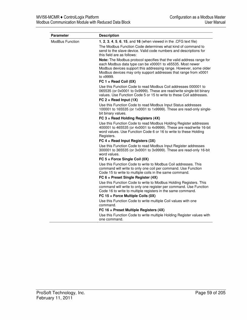
ModBus Function 1, 2, 3, 4, 5, 6, 15, and 16 (when viewed in the .CFG text file) The Modbus Function Code determines what kind of command to send to the slave device. Valid code numbers and descriptions for this field are as follows: Note: The Modbus protocol specifies that the valid address range for each Modbus data type can be x00001 to x65535. Most newer Modbus devices support this addressing range. However, some older Modbus devices may only support addresses that range from x0001 to x9999. FC 1 = Read Coil (0X)
Use this Function Code to read Modbus Coil addresses 000001 to 065535 (or 0x0001 to 0x9999). These are read/write single-bit binary values. Use Function Code 5 or 15 to write to these Coil addresses. FC 2 = Read Input (1X)
Use this Function Code to read Modbus Input Status addresses 100001 to 165535 (or 1x0001 to 1x9999). These are read-only single-bit binary values. FC 3 = Read Holding Registers (4X)
Use this Function Code to read Modbus Holding Register addresses 400001 to 465535 (or 4x0001 to 4x9999). These are read/write 16-bit word values. Use Function Code 6 or 16 to write to these Holding Registers. FC 4 = Read Input Registers (3X)
Use this Function Code to read Modbus Input Register addresses 300001 to 365535 (or 3x0001 to 3x9999). These are read-only 16-bit word values. FC 5 = Force Single Coil (0X)
Use this Function Code to write to Modbus Coil addresses. This command will write to only one coil per command. Use Function Code 15 to write to multiple coils in the same command. FC 6 = Preset Single Register (4X)
Use this Function Code to write to Modbus Holding Registers. This command will write to only one register per command. Use Function Code 16 to write to multiple registers in the same command. FC 15 = Force Multiple Coils (0X)
Use this Function Code to write multiple Coil values with one command. FC 16 = Preset Multiple Registers (4X)
Use this Function Code to write multiple Holding Register values with one command.
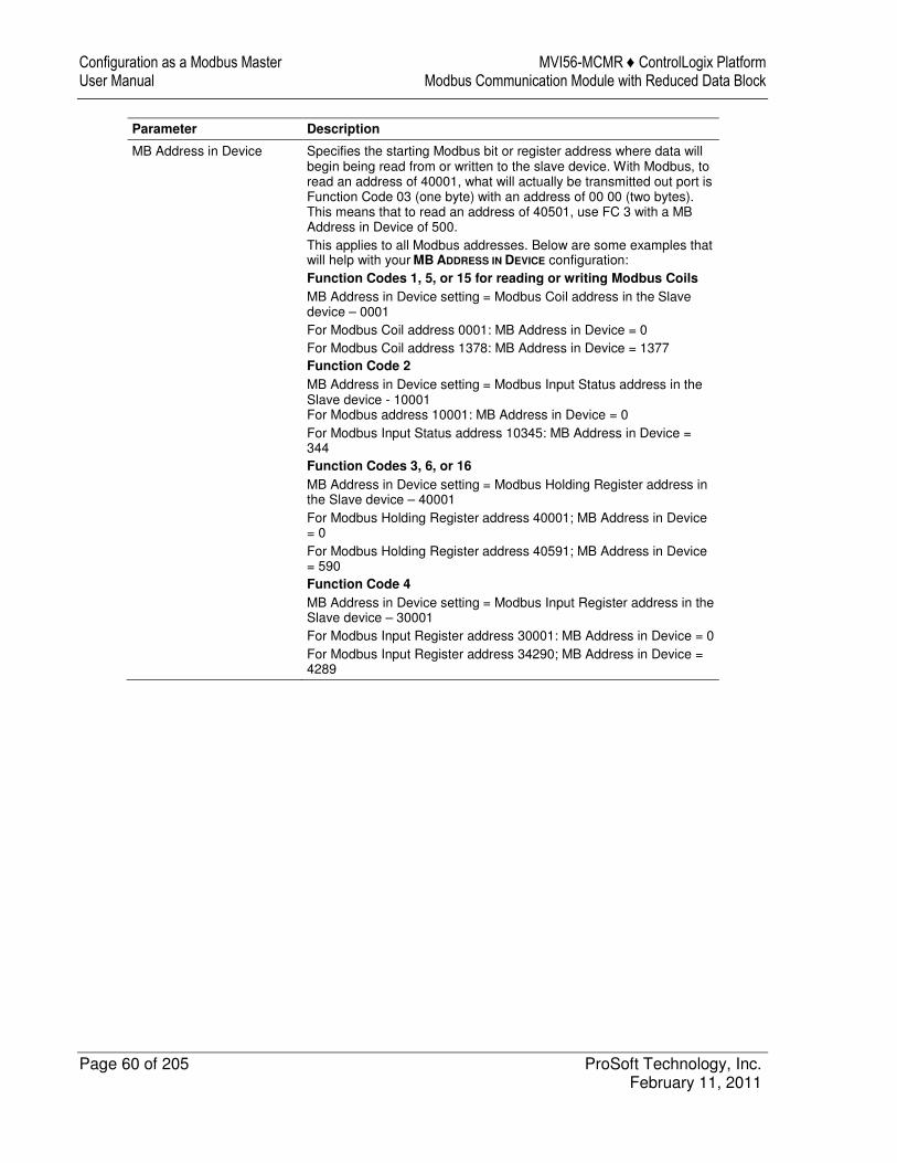
Configuration as a Modbus Master MVI56-MCMR ♦ ControlLogix Platform User Manual Modbus Communication Module with Reduced Data Block
Page 60 of 205 ProSoft Technology, Inc. February 11, 2011
Parameter Description
MB Address in Device Specifies the starting Modbus bit or register address where data will begin being read from or written to the slave device. With Modbus, to read an address of 40001, what will actually be transmitted out port is Function Code 03 (one byte) with an address of 00 00 (two bytes). This means that to read an address of 40501, use FC 3 with a MB Address in Device of 500. This applies to all Modbus addresses. Below are some examples that will help with your MB ADDRESS IN DEVICE configuration: Function Codes 1, 5, or 15 for reading or writing Modbus Coils
MB Address in Device setting = Modbus Coil address in the Slave device – 0001 For Modbus Coil address 0001: MB Address in Device = 0 For Modbus Coil address 1378: MB Address in Device = 1377 Function Code 2
MB Address in Device setting = Modbus Input Status address in the Slave device - 10001 For Modbus address 10001: MB Address in Device = 0 For Modbus Input Status address 10345: MB Address in Device = 344 Function Codes 3, 6, or 16
MB Address in Device setting = Modbus Holding Register address in the Slave device – 40001 For Modbus Holding Register address 40001; MB Address in Device = 0 For Modbus Holding Register address 40591; MB Address in Device = 590 Function Code 4
MB Address in Device setting = Modbus Input Register address in the Slave device – 30001 For Modbus Input Register address 30001: MB Address in Device = 0 For Modbus Input Register address 34290; MB Address in Device = 4289
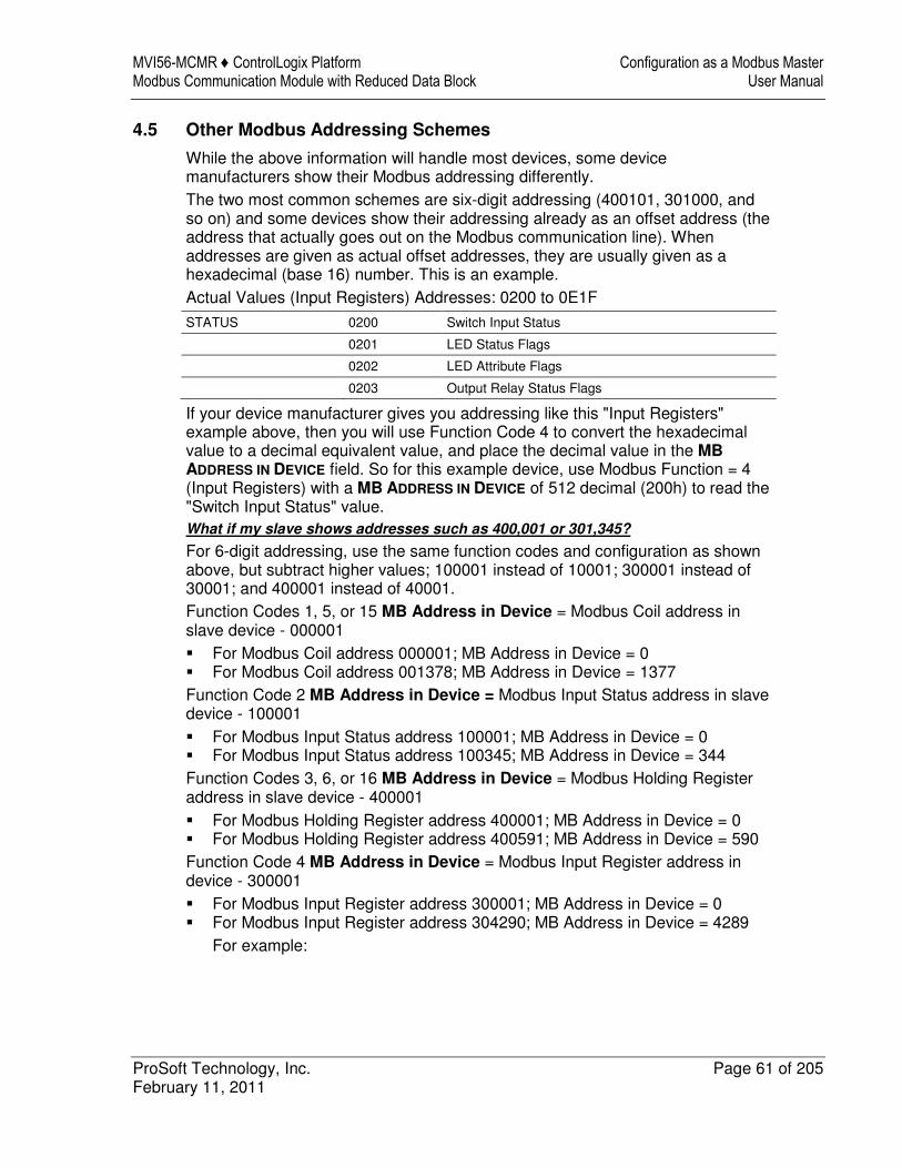
MVI56-MCMR ♦ ControlLogix Platform Configuration as a Modbus Master Modbus Communication Module with Reduced Data Block User Manual
ProSoft Technology, Inc. Page 61 of 205 February 11, 2011
4.5 Other Modbus Addressing Schemes
While the above information will handle most devices, some device manufacturers show their Modbus addressing differently. The two most common schemes are six-digit addressing (400101, 301000, and so on) and some devices show their addressing already as an offset address (the address that actually goes out on the Modbus communication line). When addresses are given as actual offset addresses, they are usually given as a hexadecimal (base 16) number. This is an example. Actual Values (Input Registers) Addresses: 0200 to 0E1F
STATUS 0200 Switch Input Status
0201 LED Status Flags
0202 LED Attribute Flags
0203 Output Relay Status Flags
If your device manufacturer gives you addressing like this "Input Registers" example above, then you will use Function Code 4 to convert the hexadecimal value to a decimal equivalent value, and place the decimal value in the MB
ADDRESS IN DEVICE field. So for this example device, use Modbus Function = 4 (Input Registers) with a MB ADDRESS IN DEVICE of 512 decimal (200h) to read the "Switch Input Status" value. What if my slave shows addresses such as 400,001 or 301,345?
For 6-digit addressing, use the same function codes and configuration as shown above, but subtract higher values; 100001 instead of 10001; 300001 instead of 30001; and 400001 instead of 40001. Function Codes 1, 5, or 15 MB Address in Device = Modbus Coil address in slave device - 000001 � For Modbus Coil address 000001; MB Address in Device = 0 � For Modbus Coil address 001378; MB Address in Device = 1377 Function Code 2 MB Address in Device = Modbus Input Status address in slave device - 100001 � For Modbus Input Status address 100001; MB Address in Device = 0 � For Modbus Input Status address 100345; MB Address in Device = 344 Function Codes 3, 6, or 16 MB Address in Device = Modbus Holding Register address in slave device - 400001 � For Modbus Holding Register address 400001; MB Address in Device = 0 � For Modbus Holding Register address 400591; MB Address in Device = 590 Function Code 4 MB Address in Device = Modbus Input Register address in device - 300001 � For Modbus Input Register address 300001; MB Address in Device = 0 � For Modbus Input Register address 304290; MB Address in Device = 4289
For example:
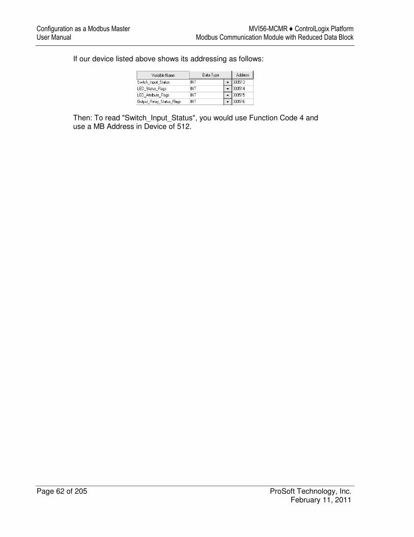
Configuration as a Modbus Master MVI56-MCMR ♦ ControlLogix Platform User Manual Modbus Communication Module with Reduced Data Block
Page 62 of 205 ProSoft Technology, Inc. February 11, 2011
If our device listed above shows its addressing as follows:
Then: To read "Switch_Input_Status", you would use Function Code 4 and use a MB Address in Device of 512.
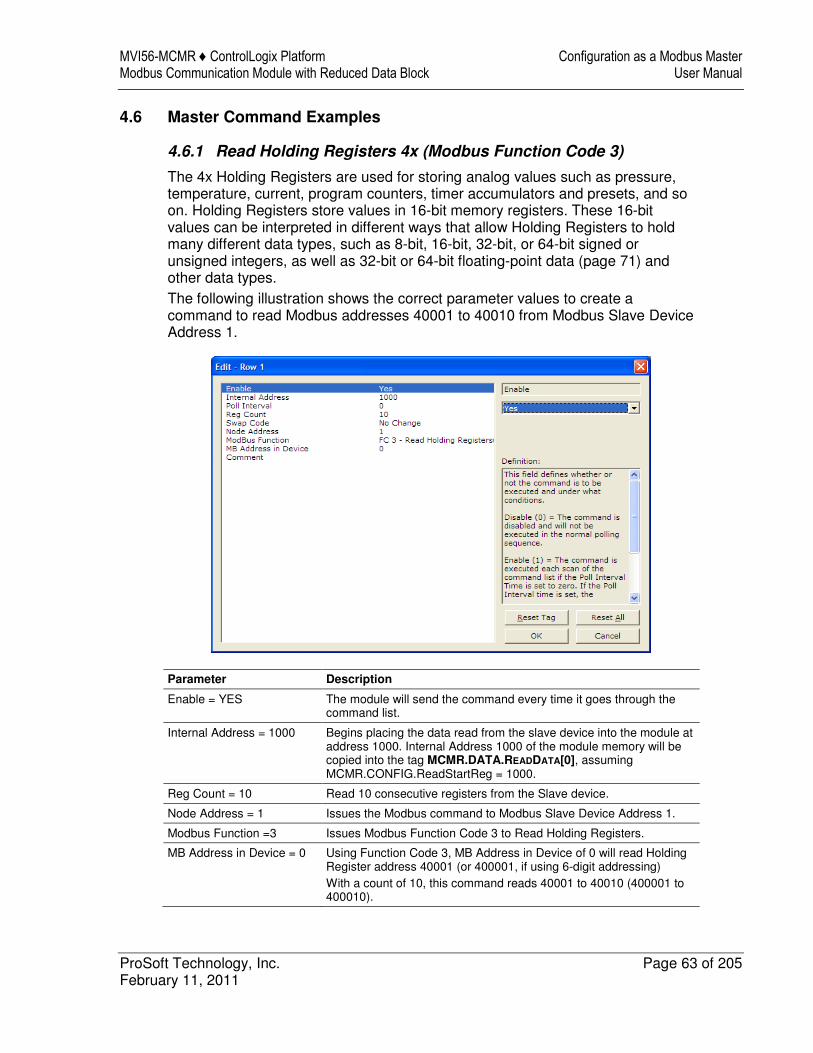
MVI56-MCMR ♦ ControlLogix Platform Configuration as a Modbus Master Modbus Communication Module with Reduced Data Block User Manual
ProSoft Technology, Inc. Page 63 of 205 February 11, 2011
4.6 Master Command Examples
4.6.1 Read Holding Registers 4x (Modbus Function Code 3)
The 4x Holding Registers are used for storing analog values such as pressure, temperature, current, program counters, timer accumulators and presets, and so on. Holding Registers store values in 16-bit memory registers. These 16-bit values can be interpreted in different ways that allow Holding Registers to hold many different data types, such as 8-bit, 16-bit, 32-bit, or 64-bit signed or unsigned integers, as well as 32-bit or 64-bit floating-point data (page 71) and other data types. The following illustration shows the correct parameter values to create a command to read Modbus addresses 40001 to 40010 from Modbus Slave Device Address 1.
Parameter Description
Enable = YES The module will send the command every time it goes through the command list.
Internal Address = 1000 Begins placing the data read from the slave device into the module at address 1000. Internal Address 1000 of the module memory will be copied into the tag MCMR.DATA.READDATA[0], assuming MCMR.CONFIG.ReadStartReg = 1000.
Reg Count = 10 Read 10 consecutive registers from the Slave device.
Node Address = 1 Issues the Modbus command to Modbus Slave Device Address 1.
Modbus Function =3 Issues Modbus Function Code 3 to Read Holding Registers.
MB Address in Device = 0 Using Function Code 3, MB Address in Device of 0 will read Holding Register address 40001 (or 400001, if using 6-digit addressing) With a count of 10, this command reads 40001 to 40010 (400001 to 400010).
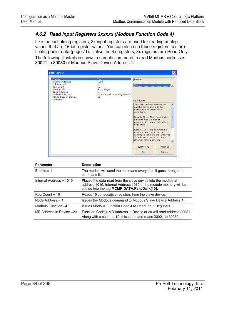
Configuration as a Modbus Master MVI56-MCMR ♦ ControlLogix Platform User Manual Modbus Communication Module with Reduced Data Block
Page 64 of 205 ProSoft Technology, Inc. February 11, 2011
4.6.2 Read Input Registers 3xxxxx (Modbus Function Code 4)
Like the 4x holding registers, 3x input registers are used for reading analog values that are 16-bit register values. You can also use these registers to store floating-point data (page 71). Unlike the 4x registers, 3x registers are Read Only. The following illustration shows a sample command to read Modbus addresses 30021 to 30030 of Modbus Slave Device Address 1.
Parameter Description
Enable = 1 The module will send the command every time it goes through the command list.
Internal Address = 1010 Places the data read from the slave device into the module at address 1010. Internal Address 1010 of the module memory will be copied into the tag MCMR.DATA.READDATA[10].
Reg Count = 10 Reads 10 consecutive registers from the slave device.
Node Address = 1 Issues the Modbus command to Modbus Slave Device Address 1.
Modbus Function =4 Issues Modbus Function Code 4 to Read Input Registers.
MB Address in Device =20 Function Code 4 MB Address in Device of 20 will read address 30021 Along with a count of 10, this command reads 30021 to 30030.
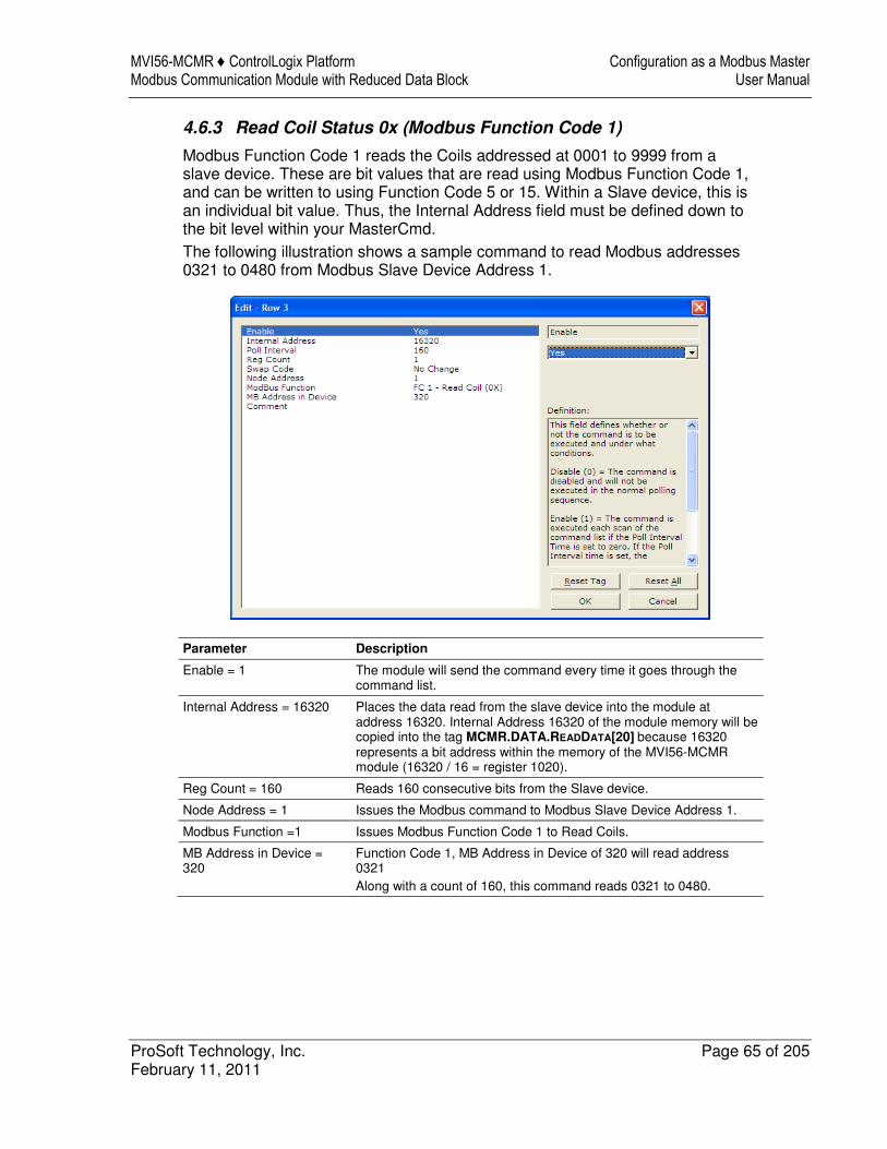
MVI56-MCMR ♦ ControlLogix Platform Configuration as a Modbus Master Modbus Communication Module with Reduced Data Block User Manual
ProSoft Technology, Inc. Page 65 of 205 February 11, 2011
4.6.3 Read Coil Status 0x (Modbus Function Code 1)
Modbus Function Code 1 reads the Coils addressed at 0001 to 9999 from a slave device. These are bit values that are read using Modbus Function Code 1, and can be written to using Function Code 5 or 15. Within a Slave device, this is an individual bit value. Thus, the Internal Address field must be defined down to the bit level within your MasterCmd. The following illustration shows a sample command to read Modbus addresses 0321 to 0480 from Modbus Slave Device Address 1.
Parameter Description
Enable = 1 The module will send the command every time it goes through the command list.
Internal Address = 16320 Places the data read from the slave device into the module at address 16320. Internal Address 16320 of the module memory will be copied into the tag MCMR.DATA.READDATA[20] because 16320 represents a bit address within the memory of the MVI56-MCMR module (16320 / 16 = register 1020).
Reg Count = 160 Reads 160 consecutive bits from the Slave device.
Node Address = 1 Issues the Modbus command to Modbus Slave Device Address 1.
Modbus Function =1 Issues Modbus Function Code 1 to Read Coils.
MB Address in Device = 320
Function Code 1, MB Address in Device of 320 will read address 0321 Along with a count of 160, this command reads 0321 to 0480.
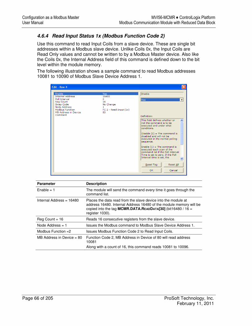
Configuration as a Modbus Master MVI56-MCMR ♦ ControlLogix Platform User Manual Modbus Communication Module with Reduced Data Block
Page 66 of 205 ProSoft Technology, Inc. February 11, 2011
4.6.4 Read Input Status 1x (Modbus Function Code 2)
Use this command to read Input Coils from a slave device. These are single bit addresses within a Modbus slave device. Unlike Coils 0x, the Input Coils are Read Only values and cannot be written to by a Modbus Master device. Also like the Coils 0x, the Internal Address field of this command is defined down to the bit level within the module memory. The following illustration shows a sample command to read Modbus addresses 10081 to 10090 of Modbus Slave Device Address 1.
Parameter Description
Enable = 1 The module will send the command every time it goes through the command list.
Internal Address = 16480 Places the data read from the slave device into the module at address 16480. Internal Address 16480 of the module memory will be copied into the tag MCMR.DATA.READDATA[30] (bit16480 / 16 = register 1030).
Reg Count = 16 Reads 16 consecutive registers from the slave device.
Node Address = 1 Issues the Modbus command to Modbus Slave Device Address 1.
Modbus Function =2 Issues Modbus Function Code 2 to Read Input Coils.
MB Address in Device = 80 Function Code 2, MB Address in Device of 80 will read address 10081 Along with a count of 16, this command reads 10081 to 10096.
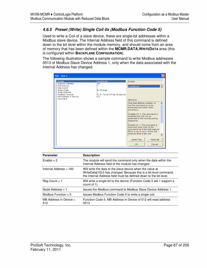
MVI56-MCMR ♦ ControlLogix Platform Configuration as a Modbus Master Modbus Communication Module with Reduced Data Block User Manual
ProSoft Technology, Inc. Page 67 of 205 February 11, 2011
4.6.5 Preset (Write) Single Coil 0x (Modbus Function Code 5)
Used to write a Coil of a slave device, these are single-bit addresses within a Modbus slave device. The Internal Address field of this command is defined down to the bit level within the module memory, and should come from an area of memory that has been defined within the MCMR.DATA.WRITEDATA area (this is configured within BACKPLANE CONFIGURATION). The following illustration shows a sample command to write Modbus addresses 0513 of Modbus Slave Device Address 1, only when the data associated with the Internal Address has changed.
Parameter Description
Enable = 2 The module will send the command only when the data within the Internal Address field of the module has changed.
Internal Address = 160 Will write the data to the slave device when the value at WriteData[10].0 has changed. Because this is a bit-level command, the Internal Address field must be defined down to the bit level.
Reg Count = 1 Will write a single bit to the device (Function Code 5 will 1 support a count of 1).
Node Address = 1 Issues the Modbus command to Modbus Slave Device Address 1.
Modbus Function = 5 Issues Modbus Function Code 5 to write a single coil.
MB Address in Device = 512
Function Code 5, MB Address in Device of 512 will read address 0513
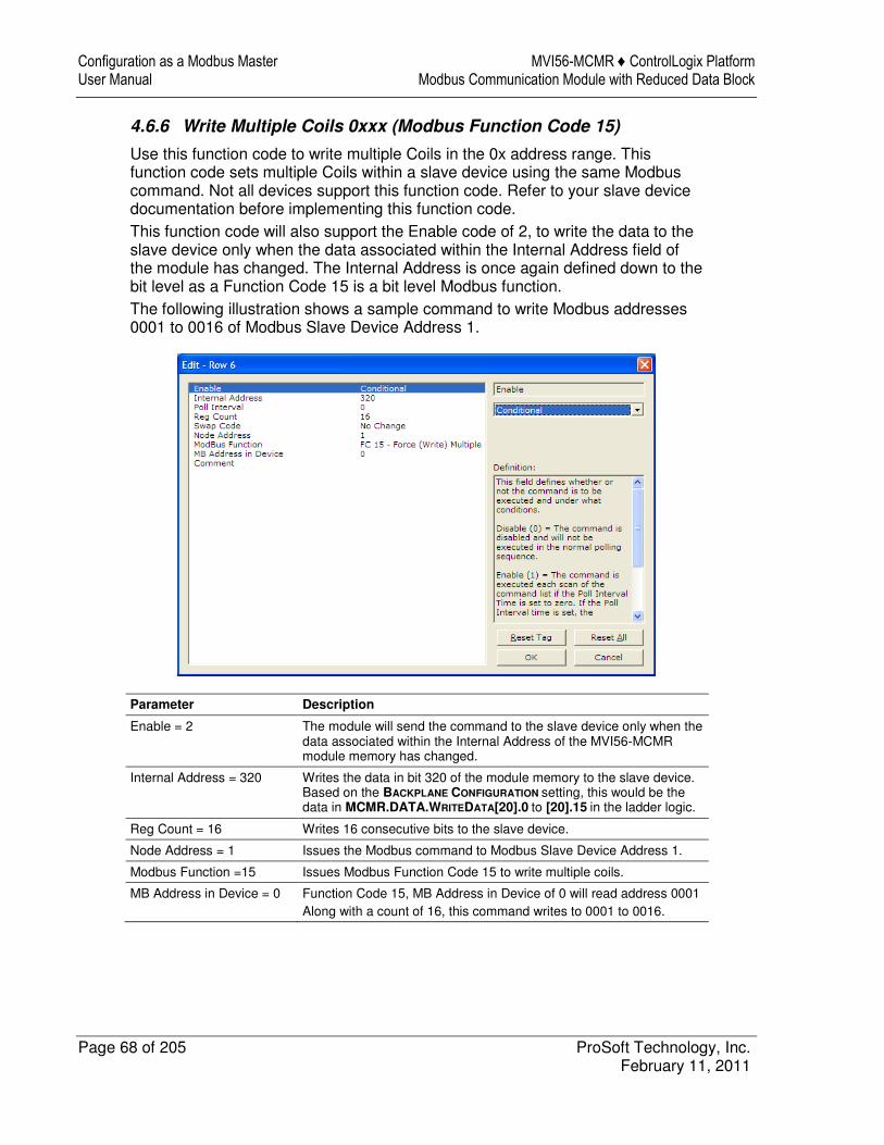
Configuration as a Modbus Master MVI56-MCMR ♦ ControlLogix Platform User Manual Modbus Communication Module with Reduced Data Block
Page 68 of 205 ProSoft Technology, Inc. February 11, 2011
4.6.6 Write Multiple Coils 0xxx (Modbus Function Code 15)
Use this function code to write multiple Coils in the 0x address range. This function code sets multiple Coils within a slave device using the same Modbus command. Not all devices support this function code. Refer to your slave device documentation before implementing this function code. This function code will also support the Enable code of 2, to write the data to the slave device only when the data associated within the Internal Address field of the module has changed. The Internal Address is once again defined down to the bit level as a Function Code 15 is a bit level Modbus function. The following illustration shows a sample command to write Modbus addresses 0001 to 0016 of Modbus Slave Device Address 1.
Parameter Description
Enable = 2 The module will send the command to the slave device only when the data associated within the Internal Address of the MVI56-MCMR module memory has changed.
Internal Address = 320 Writes the data in bit 320 of the module memory to the slave device. Based on the BACKPLANE CONFIGURATION setting, this would be the data in MCMR.DATA.WRITEDATA[20].0 to [20].15 in the ladder logic.
Reg Count = 16 Writes 16 consecutive bits to the slave device.
Node Address = 1 Issues the Modbus command to Modbus Slave Device Address 1.
Modbus Function =15 Issues Modbus Function Code 15 to write multiple coils.
MB Address in Device = 0 Function Code 15, MB Address in Device of 0 will read address 0001 Along with a count of 16, this command writes to 0001 to 0016.
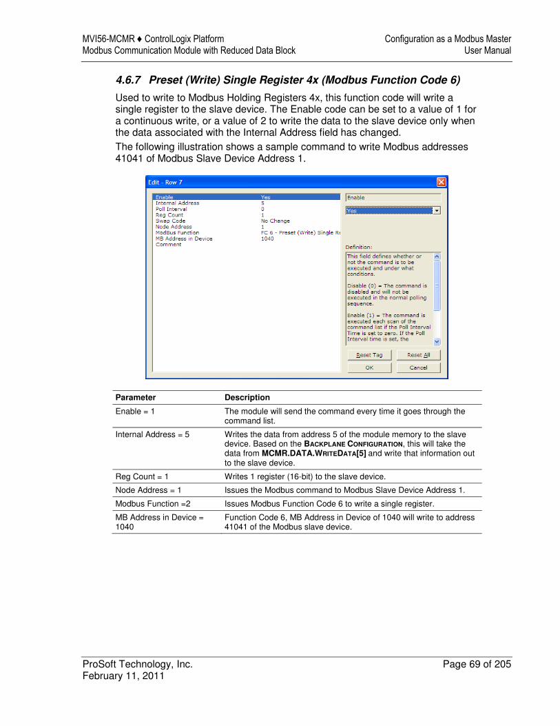
MVI56-MCMR ♦ ControlLogix Platform Configuration as a Modbus Master Modbus Communication Module with Reduced Data Block User Manual
ProSoft Technology, Inc. Page 69 of 205 February 11, 2011
4.6.7 Preset (Write) Single Register 4x (Modbus Function Code 6)
Used to write to Modbus Holding Registers 4x, this function code will write a single register to the slave device. The Enable code can be set to a value of 1 for a continuous write, or a value of 2 to write the data to the slave device only when the data associated with the Internal Address field has changed. The following illustration shows a sample command to write Modbus addresses 41041 of Modbus Slave Device Address 1.
Parameter Description
Enable = 1 The module will send the command every time it goes through the command list.
Internal Address = 5 Writes the data from address 5 of the module memory to the slave device. Based on the BACKPLANE CONFIGURATION, this will take the data from MCMR.DATA.WRITEDATA[5] and write that information out to the slave device.
Reg Count = 1 Writes 1 register (16-bit) to the slave device.
Node Address = 1 Issues the Modbus command to Modbus Slave Device Address 1.
Modbus Function =2 Issues Modbus Function Code 6 to write a single register.
MB Address in Device = 1040
Function Code 6, MB Address in Device of 1040 will write to address 41041 of the Modbus slave device.
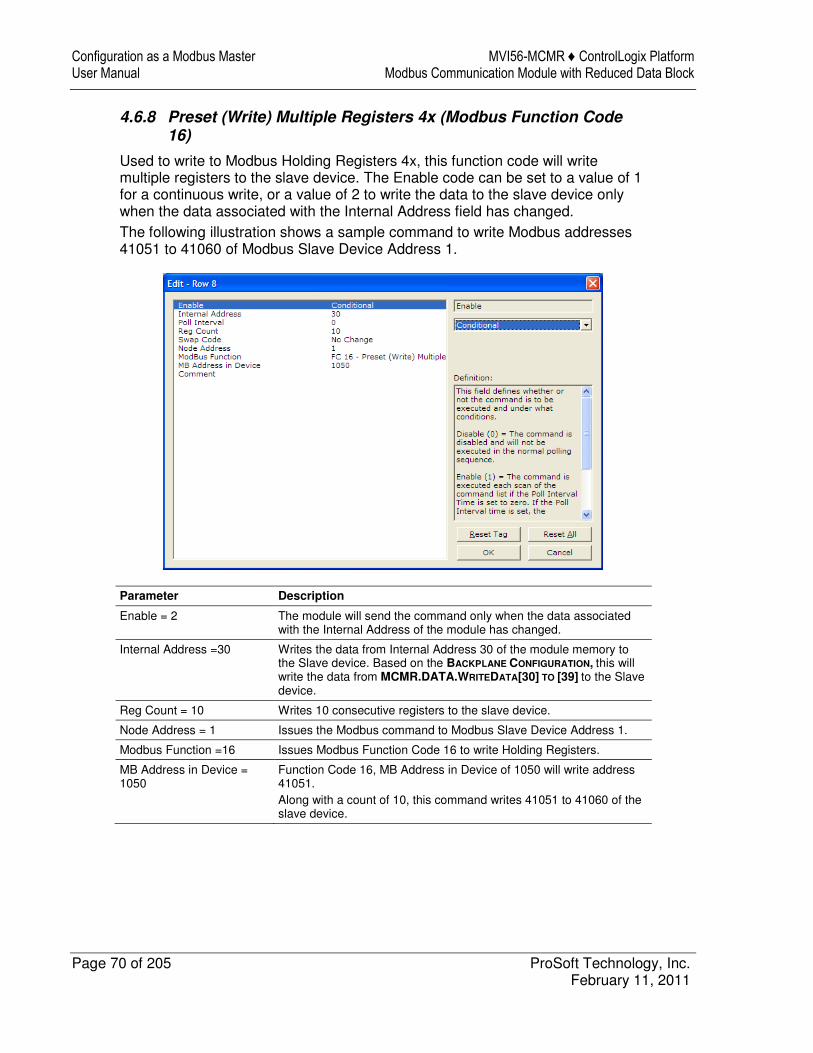
Configuration as a Modbus Master MVI56-MCMR ♦ ControlLogix Platform User Manual Modbus Communication Module with Reduced Data Block
Page 70 of 205 ProSoft Technology, Inc. February 11, 2011
4.6.8 Preset (Write) Multiple Registers 4x (Modbus Function Code 16)
Used to write to Modbus Holding Registers 4x, this function code will write multiple registers to the slave device. The Enable code can be set to a value of 1 for a continuous write, or a value of 2 to write the data to the slave device only when the data associated with the Internal Address field has changed. The following illustration shows a sample command to write Modbus addresses 41051 to 41060 of Modbus Slave Device Address 1.
Parameter Description
Enable = 2 The module will send the command only when the data associated with the Internal Address of the module has changed.
Internal Address =30 Writes the data from Internal Address 30 of the module memory to the Slave device. Based on the BACKPLANE CONFIGURATION, this will write the data from MCMR.DATA.WRITEDATA[30] TO [39] to the Slave device.
Reg Count = 10 Writes 10 consecutive registers to the slave device.
Node Address = 1 Issues the Modbus command to Modbus Slave Device Address 1.
Modbus Function =16 Issues Modbus Function Code 16 to write Holding Registers.
MB Address in Device = 1050
Function Code 16, MB Address in Device of 1050 will write address 41051. Along with a count of 10, this command writes 41051 to 41060 of the slave device.
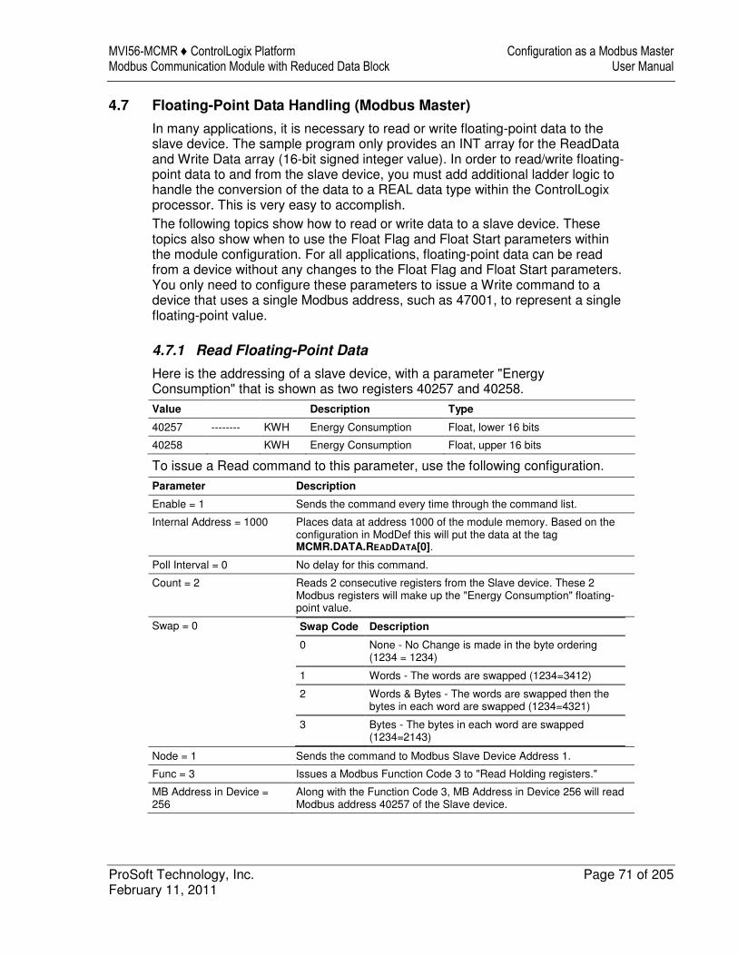
MVI56-MCMR ♦ ControlLogix Platform Configuration as a Modbus Master Modbus Communication Module with Reduced Data Block User Manual
ProSoft Technology, Inc. Page 71 of 205 February 11, 2011
4.7 Floating-Point Data Handling (Modbus Master)
In many applications, it is necessary to read or write floating-point data to the slave device. The sample program only provides an INT array for the ReadData and Write Data array (16-bit signed integer value). In order to read/write floating-point data to and from the slave device, you must add additional ladder logic to handle the conversion of the data to a REAL data type within the ControlLogix processor. This is very easy to accomplish. The following topics show how to read or write data to a slave device. These topics also show when to use the Float Flag and Float Start parameters within the module configuration. For all applications, floating-point data can be read from a device without any changes to the Float Flag and Float Start parameters. You only need to configure these parameters to issue a Write command to a device that uses a single Modbus address, such as 47001, to represent a single floating-point value.
4.7.1 Read Floating-Point Data
Here is the addressing of a slave device, with a parameter "Energy Consumption" that is shown as two registers 40257 and 40258.
Value Description Type
40257 -------- KWH Energy Consumption Float, lower 16 bits
40258 KWH Energy Consumption Float, upper 16 bits
To issue a Read command to this parameter, use the following configuration.
Parameter Description
Enable = 1 Sends the command every time through the command list.
Internal Address = 1000 Places data at address 1000 of the module memory. Based on the configuration in ModDef this will put the data at the tag MCMR.DATA.READDATA[0].
Poll Interval = 0 No delay for this command.
Count = 2 Reads 2 consecutive registers from the Slave device. These 2 Modbus registers will make up the "Energy Consumption" floating-point value.
Swap = 0 Swap Code Description
0 None - No Change is made in the byte ordering (1234 = 1234)
1 Words - The words are swapped (1234=3412)
2 Words & Bytes - The words are swapped then the bytes in each word are swapped (1234=4321)
3 Bytes - The bytes in each word are swapped (1234=2143)
Node = 1 Sends the command to Modbus Slave Device Address 1.
Func = 3 Issues a Modbus Function Code 3 to "Read Holding registers."
MB Address in Device = 256
Along with the Function Code 3, MB Address in Device 256 will read Modbus address 40257 of the Slave device.
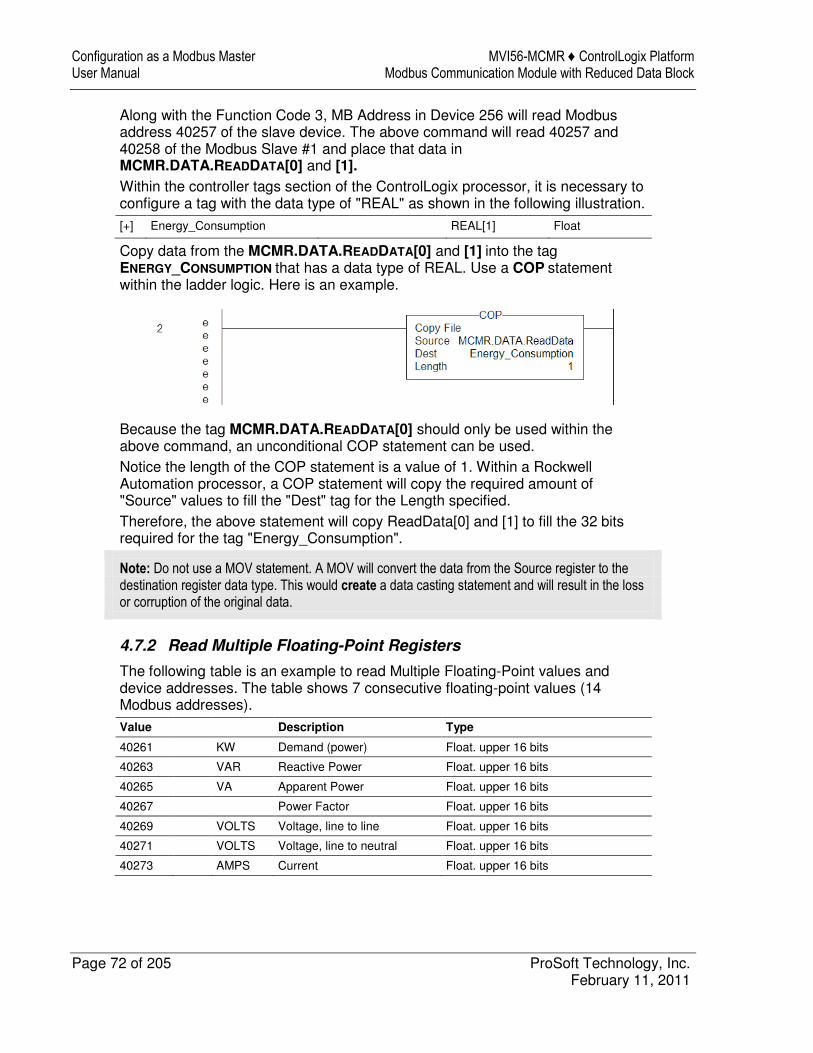
Configuration as a Modbus Master MVI56-MCMR ♦ ControlLogix Platform User Manual Modbus Communication Module with Reduced Data Block
Page 72 of 205 ProSoft Technology, Inc. February 11, 2011
Along with the Function Code 3, MB Address in Device 256 will read Modbus address 40257 of the slave device. The above command will read 40257 and 40258 of the Modbus Slave #1 and place that data in MCMR.DATA.READDATA[0] and [1]. Within the controller tags section of the ControlLogix processor, it is necessary to configure a tag with the data type of "REAL" as shown in the following illustration.
[+] Energy_Consumption REAL[1] Float
Copy data from the MCMR.DATA.READDATA[0] and [1] into the tag ENERGY_CONSUMPTION that has a data type of REAL. Use a COP statement within the ladder logic. Here is an example.
Because the tag MCMR.DATA.READDATA[0] should only be used within the above command, an unconditional COP statement can be used. Notice the length of the COP statement is a value of 1. Within a Rockwell Automation processor, a COP statement will copy the required amount of "Source" values to fill the "Dest" tag for the Length specified. Therefore, the above statement will copy ReadData[0] and [1] to fill the 32 bits required for the tag "Energy_Consumption".
Note: Do not use a MOV statement. A MOV will convert the data from the Source register to the destination register data type. This would create a data casting statement and will result in the loss or corruption of the original data.
4.7.2 Read Multiple Floating-Point Registers
The following table is an example to read Multiple Floating-Point values and device addresses. The table shows 7 consecutive floating-point values (14 Modbus addresses).
Value Description Type
40261 KW Demand (power) Float. upper 16 bits
40263 VAR Reactive Power Float. upper 16 bits
40265 VA Apparent Power Float. upper 16 bits
40267 Power Factor Float. upper 16 bits
40269 VOLTS Voltage, line to line Float. upper 16 bits
40271 VOLTS Voltage, line to neutral Float. upper 16 bits
40273 AMPS Current Float. upper 16 bits
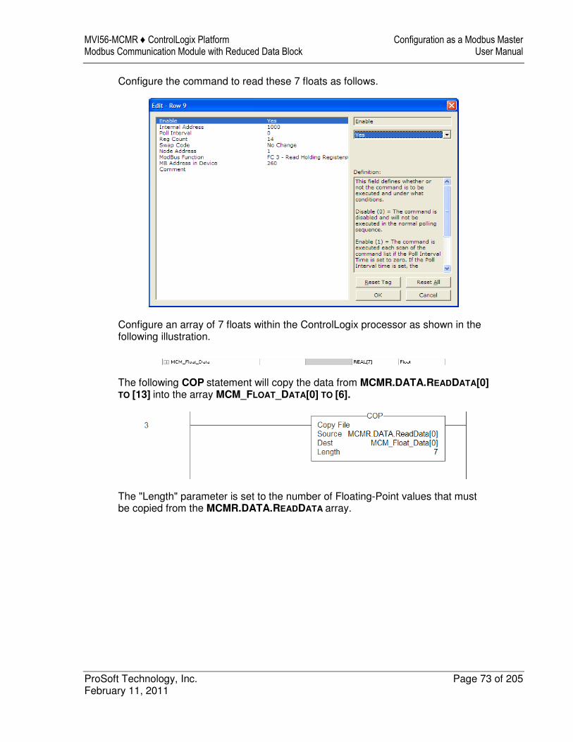
MVI56-MCMR ♦ ControlLogix Platform Configuration as a Modbus Master Modbus Communication Module with Reduced Data Block User Manual
ProSoft Technology, Inc. Page 73 of 205 February 11, 2011
Configure the command to read these 7 floats as follows.
Configure an array of 7 floats within the ControlLogix processor as shown in the following illustration.
The following COP statement will copy the data from MCMR.DATA.READDATA[0] TO [13] into the array MCM_FLOAT_DATA[0] TO [6].
The "Length" parameter is set to the number of Floating-Point values that must be copied from the MCMR.DATA.READDATA array.
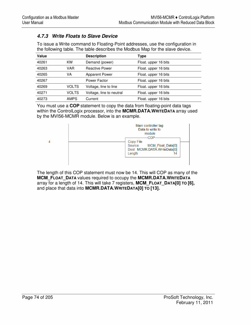
Configuration as a Modbus Master MVI56-MCMR ♦ ControlLogix Platform User Manual Modbus Communication Module with Reduced Data Block
Page 74 of 205 ProSoft Technology, Inc. February 11, 2011
4.7.3 Write Floats to Slave Device
To issue a Write command to Floating-Point addresses, use the configuration in the following table. The table describes the Modbus Map for the slave device.
Value Description Type
40261 KW Demand (power) Float. upper 16 bits
40263 VAR Reactive Power Float. upper 16 bits
40265 VA Apparent Power Float. upper 16 bits
40267 Power Factor Float. upper 16 bits
40269 VOLTS Voltage, line to line Float. upper 16 bits
40271 VOLTS Voltage, line to neutral Float. upper 16 bits
40273 AMPS Current Float. upper 16 bits
You must use a COP statement to copy the data from floating-point data tags within the ControlLogix processor, into the MCMR.DATA.WRITEDATA array used by the MVI56-MCMR module. Below is an example.
The length of this COP statement must now be 14. This will COP as many of the MCM_FLOAT_DATA values required to occupy the MCMR.DATA.WRITEDATA
array for a length of 14. This will take 7 registers, MCM_FLOAT_DATA[0] TO [6], and place that data into MCMR.DATA.WRITEDATA[0] TO [13].
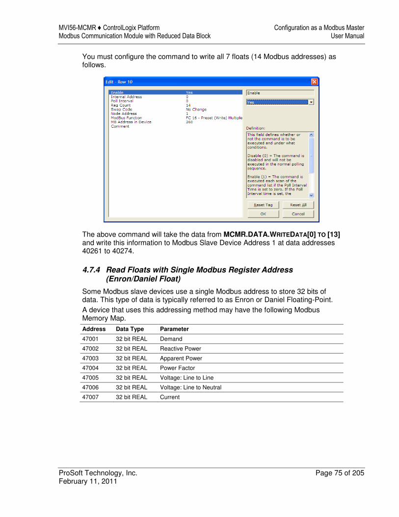
MVI56-MCMR ♦ ControlLogix Platform Configuration as a Modbus Master Modbus Communication Module with Reduced Data Block User Manual
ProSoft Technology, Inc. Page 75 of 205 February 11, 2011
You must configure the command to write all 7 floats (14 Modbus addresses) as follows.
The above command will take the data from MCMR.DATA.WRITEDATA[0] TO [13] and write this information to Modbus Slave Device Address 1 at data addresses 40261 to 40274.
4.7.4 Read Floats with Single Modbus Register Address (Enron/Daniel Float)
Some Modbus slave devices use a single Modbus address to store 32 bits of data. This type of data is typically referred to as Enron or Daniel Floating-Point. A device that uses this addressing method may have the following Modbus Memory Map. Address Data Type Parameter
47001 32 bit REAL Demand
47002 32 bit REAL Reactive Power
47003 32 bit REAL Apparent Power
47004 32 bit REAL Power Factor
47005 32 bit REAL Voltage: Line to Line
47006 32 bit REAL Voltage: Line to Neutral
47007 32 bit REAL Current
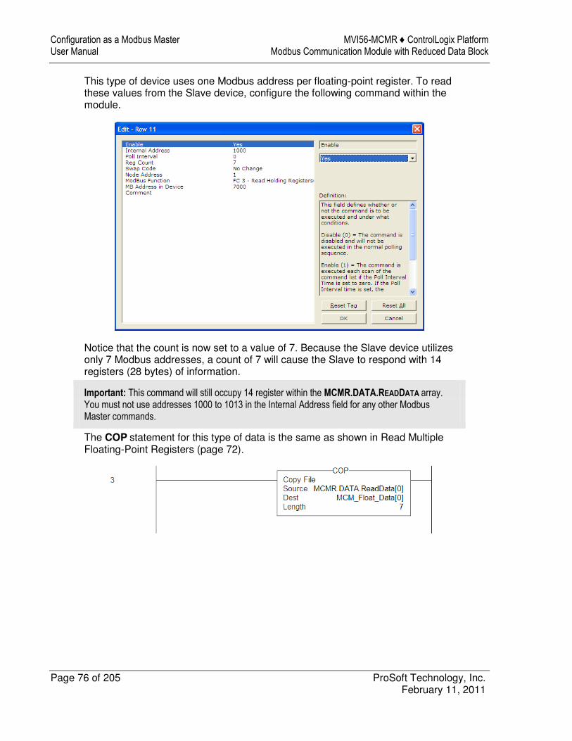
Configuration as a Modbus Master MVI56-MCMR ♦ ControlLogix Platform User Manual Modbus Communication Module with Reduced Data Block
Page 76 of 205 ProSoft Technology, Inc. February 11, 2011
This type of device uses one Modbus address per floating-point register. To read these values from the Slave device, configure the following command within the module.
Notice that the count is now set to a value of 7. Because the Slave device utilizes only 7 Modbus addresses, a count of 7 will cause the Slave to respond with 14 registers (28 bytes) of information.
Important: This command will still occupy 14 register within the MCMR.DATA.READDATA array. You must not use addresses 1000 to 1013 in the Internal Address field for any other Modbus Master commands.
The COP statement for this type of data is the same as shown in Read Multiple Floating-Point Registers (page 72).
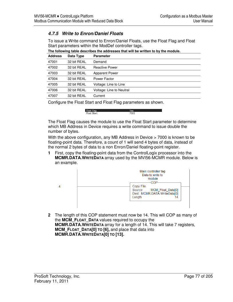
MVI56-MCMR ♦ ControlLogix Platform Configuration as a Modbus Master Modbus Communication Module with Reduced Data Block User Manual
ProSoft Technology, Inc. Page 77 of 205 February 11, 2011
4.7.5 Write to Enron/Daniel Floats
To issue a Write command to Enron/Daniel Floats, use the Float Flag and Float Start parameters within the ModDef controller tags. The following table describes the addresses that will be written to by the module.
Address Data Type Parameter
47001 32 bit REAL Demand
47002 32 bit REAL Reactive Power
47003 32 bit REAL Apparent Power
47004 32 bit REAL Power Factor
47005 32 bit REAL Voltage: Line to Line
47006 32 bit REAL Voltage: Line to Neutral
47007 32 bit REAL Current
Configure the Float Start and Float Flag parameters as shown.
The Float Flag causes the module to use the Float Start parameter to determine which MB Address in Device requires a write command to issue double the number of bytes. With the above configuration, any MB Address in Device > 7000 is known to be floating-point data. Therefore, a count of 1 will send 4 bytes of data, instead of the normal 2 bytes of data to a non Enron/Daniel floating-point register. 1 First, copy the floating-point data from the ControlLogix processor into the
MCMR.DATA.WRITEDATA array used by the MVI56-MCMR module. Below is an example.
2 The length of this COP statement must now be 14. This will COP as many of the MCM_FLOAT_DATA values required to occupy the MCMR.DATA.WRITEDATA array for a length of 14. This will take 7 registers, MCM_FLOAT_DATA[0] TO [6], and place that data into MCMR.DATA.WRITEDATA[0] TO [13].
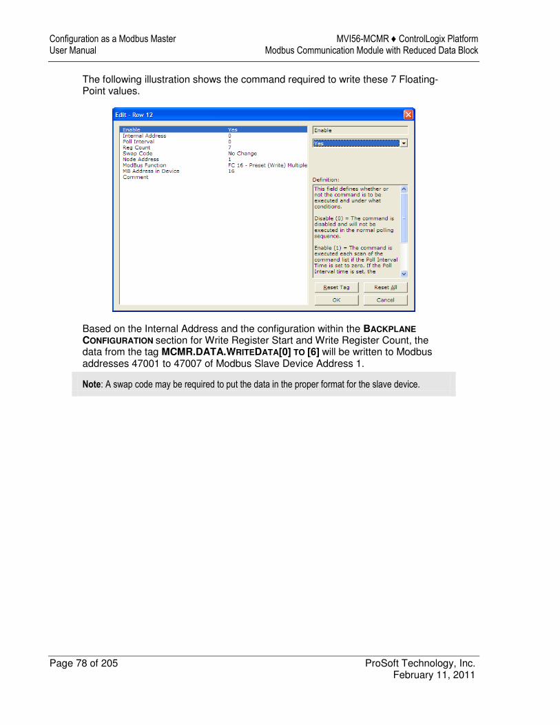
Configuration as a Modbus Master MVI56-MCMR ♦ ControlLogix Platform User Manual Modbus Communication Module with Reduced Data Block
Page 78 of 205 ProSoft Technology, Inc. February 11, 2011
The following illustration shows the command required to write these 7 Floating-Point values.
Based on the Internal Address and the configuration within the BACKPLANE
CONFIGURATION section for Write Register Start and Write Register Count, the data from the tag MCMR.DATA.WRITEDATA[0] TO [6] will be written to Modbus addresses 47001 to 47007 of Modbus Slave Device Address 1.
Note: A swap code may be required to put the data in the proper format for the slave device.
MVI56-MCMR ♦ ControlLogix Platform Configuration as a Modbus Slave Modbus Communication Module with Reduced Data Block User Manual
ProSoft Technology, Inc. Page 79 of 205 February 11, 2011
5 Configuration as a Modbus Slave
In This Chapter
� Overview ............................................................................................... 80
� Configuration File Settings .................................................................... 81
� Slave Configuration ............................................................................... 86
� Floating-Point Data Handling (Modbus Slave) ....................................... 88
Configuration as a Modbus Slave MVI56-MCMR ♦ ControlLogix Platform User Manual Modbus Communication Module with Reduced Data Block
Page 80 of 205 ProSoft Technology, Inc. February 11, 2011
5.1 Overview
When configuring the module as a slave, you will be providing a Modbus Memory Map to the person who is programming the Master side of the communications.
Note: If you are using the Sample Ladder Logic, the transfer of data is already done.
Information that is to be read by the Modbus Master device will be placed in the MCMR.DATA.WRITEDATA array as this will be pushed out to the module so that values from the ControlLogix processor can be read by the Modbus Master. Information that must be written to the ControlLogix processor from the Modbus Master device will be placed into the MCMR.DATA.READDATA array. To configure module as a Modbus Slave, you must determine how much data you must transfer to and from the module, to the Modbus Master. The sample ladder file is configured to transfer 600 16-bit registers in each direction. If more than that is required, please see Applications Requiring More Than 600 Registers of ReadData or WriteData.
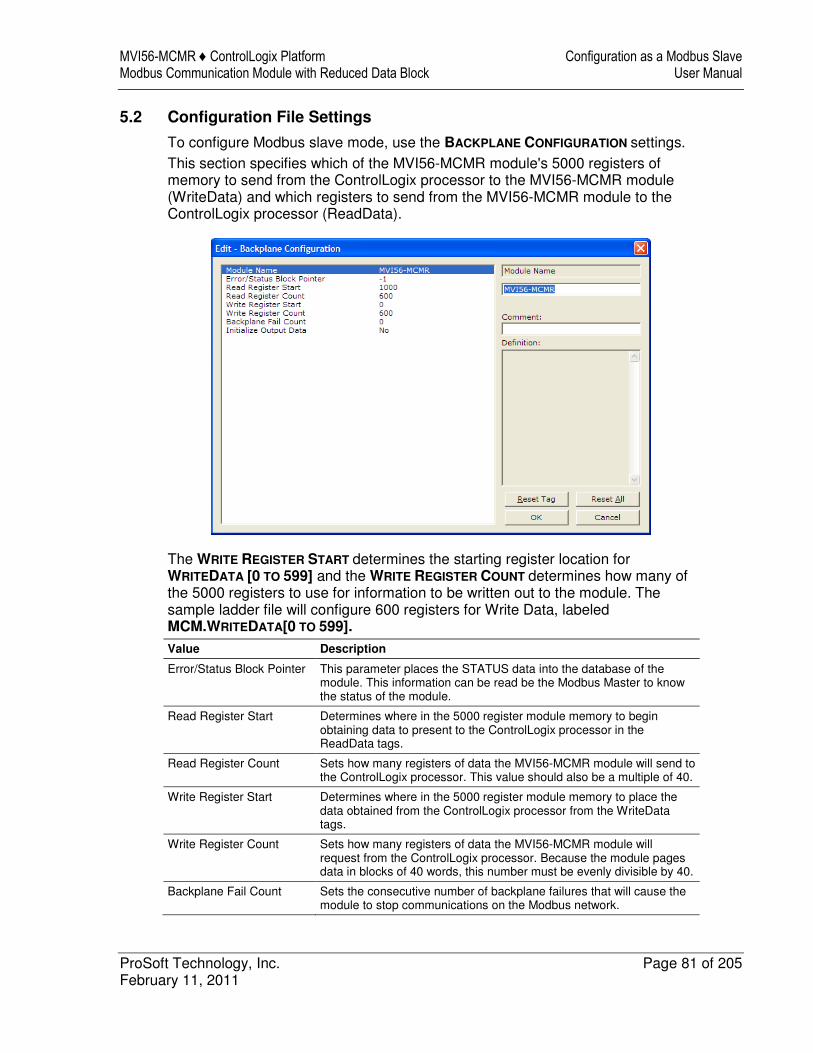
MVI56-MCMR ♦ ControlLogix Platform Configuration as a Modbus Slave Modbus Communication Module with Reduced Data Block User Manual
ProSoft Technology, Inc. Page 81 of 205 February 11, 2011
5.2 Configuration File Settings
To configure Modbus slave mode, use the BACKPLANE CONFIGURATION settings. This section specifies which of the MVI56-MCMR module's 5000 registers of memory to send from the ControlLogix processor to the MVI56-MCMR module (WriteData) and which registers to send from the MVI56-MCMR module to the ControlLogix processor (ReadData).
The WRITE REGISTER START determines the starting register location for WRITEDATA [0 TO 599] and the WRITE REGISTER COUNT determines how many of the 5000 registers to use for information to be written out to the module. The sample ladder file will configure 600 registers for Write Data, labeled MCM.WRITEDATA[0 TO 599].
Value Description
Error/Status Block Pointer This parameter places the STATUS data into the database of the module. This information can be read be the Modbus Master to know the status of the module.
Read Register Start Determines where in the 5000 register module memory to begin obtaining data to present to the ControlLogix processor in the ReadData tags.
Read Register Count Sets how many registers of data the MVI56-MCMR module will send to the ControlLogix processor. This value should also be a multiple of 40.
Write Register Start Determines where in the 5000 register module memory to place the data obtained from the ControlLogix processor from the WriteData tags.
Write Register Count Sets how many registers of data the MVI56-MCMR module will request from the ControlLogix processor. Because the module pages data in blocks of 40 words, this number must be evenly divisible by 40.
Backplane Fail Count Sets the consecutive number of backplane failures that will cause the module to stop communications on the Modbus network.
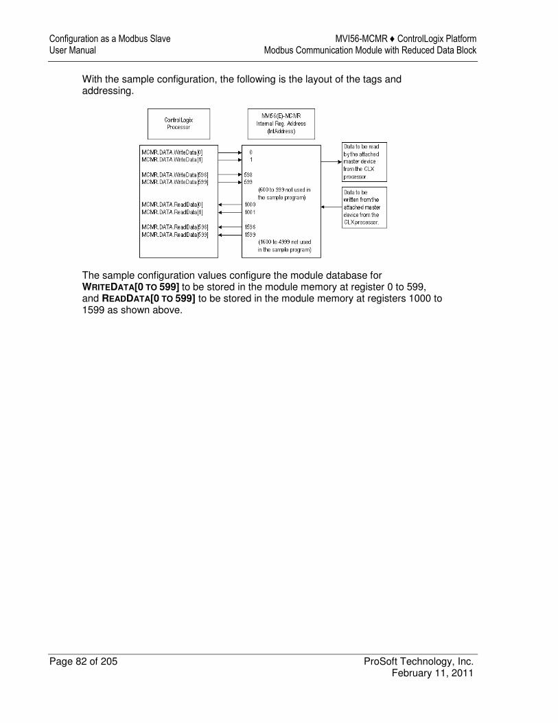
Configuration as a Modbus Slave MVI56-MCMR ♦ ControlLogix Platform User Manual Modbus Communication Module with Reduced Data Block
Page 82 of 205 ProSoft Technology, Inc. February 11, 2011
With the sample configuration, the following is the layout of the tags and addressing.
The sample configuration values configure the module database for WRITEDATA[0 TO 599] to be stored in the module memory at register 0 to 599, and READDATA[0 TO 599] to be stored in the module memory at registers 1000 to 1599 as shown above.
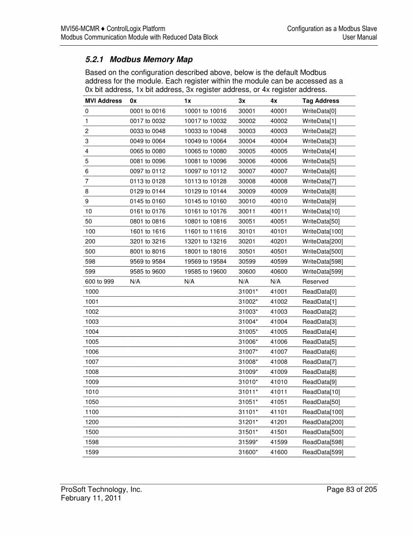
MVI56-MCMR ♦ ControlLogix Platform Configuration as a Modbus Slave Modbus Communication Module with Reduced Data Block User Manual
ProSoft Technology, Inc. Page 83 of 205 February 11, 2011
5.2.1 Modbus Memory Map
Based on the configuration described above, below is the default Modbus address for the module. Each register within the module can be accessed as a 0x bit address, 1x bit address, 3x register address, or 4x register address.
MVI Address 0x 1x 3x 4x Tag Address
0 0001 to 0016 10001 to 10016 30001 40001 WriteData[0]
1 0017 to 0032 10017 to 10032 30002 40002 WriteData[1]
2 0033 to 0048 10033 to 10048 30003 40003 WriteData[2]
3 0049 to 0064 10049 to 10064 30004 40004 WriteData[3]
4 0065 to 0080 10065 to 10080 30005 40005 WriteData[4]
5 0081 to 0096 10081 to 10096 30006 40006 WriteData[5]
6 0097 to 0112 10097 to 10112 30007 40007 WriteData[6]
7 0113 to 0128 10113 to 10128 30008 40008 WriteData[7]
8 0129 to 0144 10129 to 10144 30009 40009 WriteData[8]
9 0145 to 0160 10145 to 10160 30010 40010 WriteData[9]
10 0161 to 0176 10161 to 10176 30011 40011 WriteData[10]
50 0801 to 0816 10801 to 10816 30051 40051 WriteData[50]
100 1601 to 1616 11601 to 11616 30101 40101 WriteData[100]
200 3201 to 3216 13201 to 13216 30201 40201 WriteData[200]
500 8001 to 8016 18001 to 18016 30501 40501 WriteData[500]
598 9569 to 9584 19569 to 19584 30599 40599 WriteData[598]
599 9585 to 9600 19585 to 19600 30600 40600 WriteData[599]
600 to 999 N/A N/A N/A N/A Reserved
1000 31001* 41001 ReadData[0]
1001 31002* 41002 ReadData[1]
1002 31003* 41003 ReadData[2]
1003 31004* 41004 ReadData[3]
1004 31005* 41005 ReadData[4]
1005 31006* 41006 ReadData[5]
1006 31007* 41007 ReadData[6]
1007 31008* 41008 ReadData[7]
1008 31009* 41009 ReadData[8]
1009 31010* 41010 ReadData[9]
1010 31011* 41011 ReadData[10]
1050 31051* 41051 ReadData[50]
1100 31101* 41101 ReadData[100]
1200 31201* 41201 ReadData[200]
1500 31501* 41501 ReadData[500]
1598 31599* 41599 ReadData[598]
1599 31600* 41600 ReadData[599]
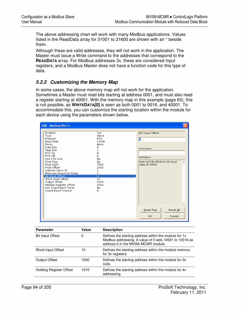
Configuration as a Modbus Slave MVI56-MCMR ♦ ControlLogix Platform User Manual Modbus Communication Module with Reduced Data Block
Page 84 of 205 ProSoft Technology, Inc. February 11, 2011
The above addressing chart will work with many Modbus applications. Values listed in the ReadData array for 31001 to 31600 are shown with an * beside them. Although these are valid addresses, they will not work in the application. The Master must issue a Write command to the addresses that correspond to the READDATA array. For Modbus addresses 3x, these are considered Input registers, and a Modbus Master does not have a function code for this type of data.
5.2.2 Customizing the Memory Map
In some cases, the above memory map will not work for the application. Sometimes a Master must read bits starting at address 0001, and must also read a register starting at 40001. With the memory map in this example (page 83), this is not possible, as WRITEDATA[0] is seen as both 0001 to 0016, and 40001. To accommodate this, you can customize the starting location within the module for each device using the parameters shown below.
Parameter Value Description
Bit Input Offset 0 Defines the starting address within the module for 1x Modbus addressing. A value of 0 sets 10001 to 10016 as address 0 in the MVI56-MCMR module.
Word Input Offset 10 Defines the starting address within the module memory for 3x registers.
Output Offset 1000 Defines the starting address within the module for 0x coils.
Holding Register Offset 1010 Defines the starting address within the module for 4x addressing.
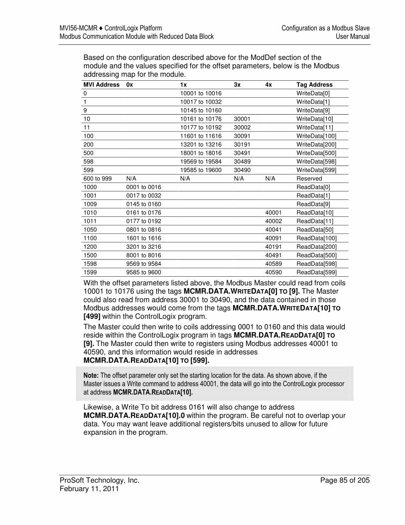
MVI56-MCMR ♦ ControlLogix Platform Configuration as a Modbus Slave Modbus Communication Module with Reduced Data Block User Manual
ProSoft Technology, Inc. Page 85 of 205 February 11, 2011
Based on the configuration described above for the ModDef section of the module and the values specified for the offset parameters, below is the Modbus addressing map for the module. MVI Address 0x 1x 3x 4x Tag Address
0 10001 to 10016 WriteData[0] 1 10017 to 10032 WriteData[1] 9 10145 to 10160 WriteData[9] 10 10161 to 10176 30001 WriteData[10] 11 10177 to 10192 30002 WriteData[11] 100 11601 to 11616 30091 WriteData[100] 200 13201 to 13216 30191 WriteData[200] 500 18001 to 18016 30491 WriteData[500] 598 19569 to 19584 30489 WriteData[598] 599 19585 to 19600 30490 WriteData[599] 600 to 999 N/A N/A N/A N/A Reserved 1000 0001 to 0016 ReadData[0] 1001 0017 to 0032 ReadData[1] 1009 0145 to 0160 ReadData[9] 1010 0161 to 0176 40001 ReadData[10] 1011 0177 to 0192 40002 ReadData[11] 1050 0801 to 0816 40041 ReadData[50] 1100 1601 to 1616 40091 ReadData[100] 1200 3201 to 3216 40191 ReadData[200] 1500 8001 to 8016 40491 ReadData[500] 1598 9569 to 9584 40589 ReadData[598] 1599 9585 to 9600 40590 ReadData[599]
With the offset parameters listed above, the Modbus Master could read from coils 10001 to 10176 using the tags MCMR.DATA.WRITEDATA[0] TO [9]. The Master could also read from address 30001 to 30490, and the data contained in those Modbus addresses would come from the tags MCMR.DATA.WRITEDATA[10] TO
[499] within the ControlLogix program. The Master could then write to coils addressing 0001 to 0160 and this data would reside within the ControlLogix program in tags MCMR.DATA.READDATA[0] TO
[9]. The Master could then write to registers using Modbus addresses 40001 to 40590, and this information would reside in addresses MCMR.DATA.READDATA[10] TO [599].
Note: The offset parameter only set the starting location for the data. As shown above, if the Master issues a Write command to address 40001, the data will go into the ControlLogix processor at address MCMR.DATA.READDATA[10].
Likewise, a Write To bit address 0161 will also change to address MCMR.DATA.READDATA[10].0 within the program. Be careful not to overlap your data. You may want leave additional registers/bits unused to allow for future expansion in the program.
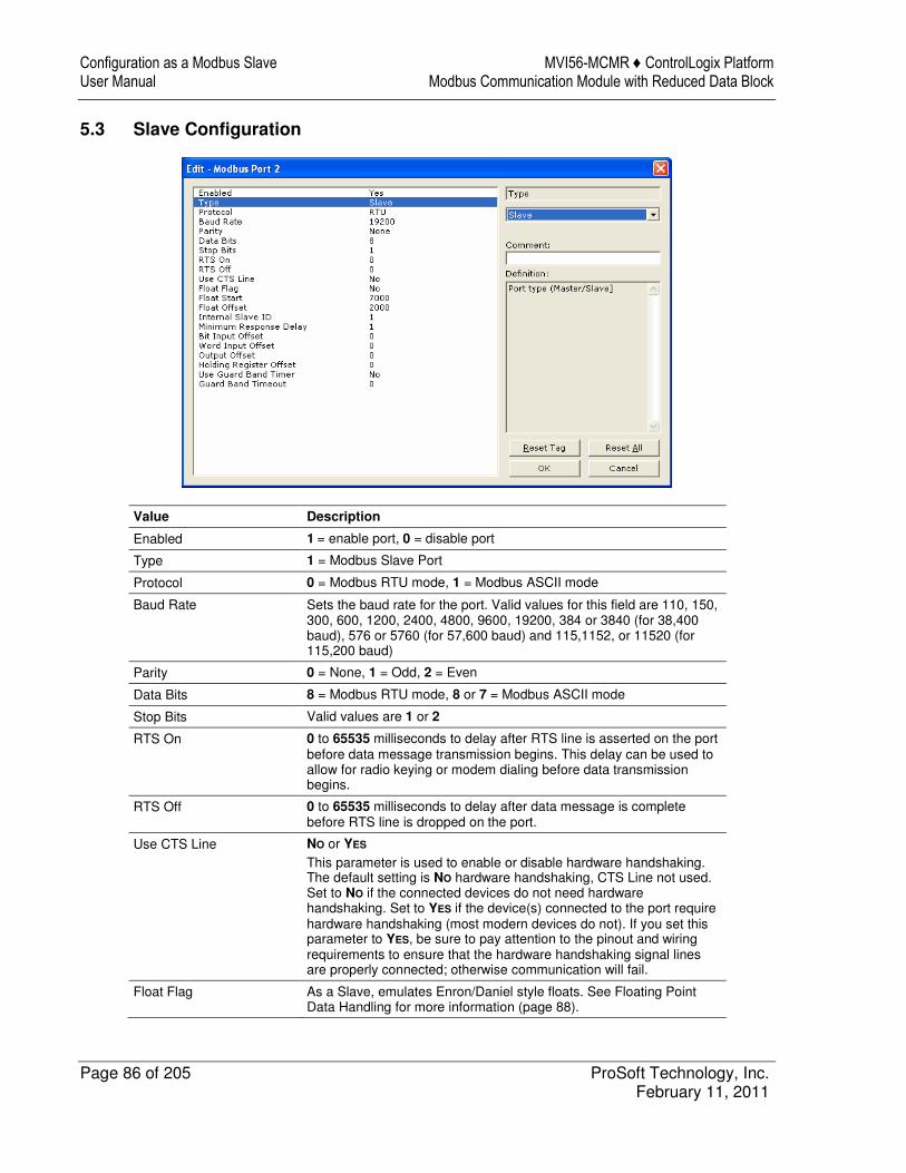
Configuration as a Modbus Slave MVI56-MCMR ♦ ControlLogix Platform User Manual Modbus Communication Module with Reduced Data Block
Page 86 of 205 ProSoft Technology, Inc. February 11, 2011
5.3 Slave Configuration
Value Description
Enabled 1 = enable port, 0 = disable port
Type 1 = Modbus Slave Port
Protocol 0 = Modbus RTU mode, 1 = Modbus ASCII mode
Baud Rate Sets the baud rate for the port. Valid values for this field are 110, 150, 300, 600, 1200, 2400, 4800, 9600, 19200, 384 or 3840 (for 38,400 baud), 576 or 5760 (for 57,600 baud) and 115,1152, or 11520 (for 115,200 baud)
Parity 0 = None, 1 = Odd, 2 = Even
Data Bits 8 = Modbus RTU mode, 8 or 7 = Modbus ASCII mode
Stop Bits Valid values are 1 or 2
RTS On 0 to 65535 milliseconds to delay after RTS line is asserted on the port before data message transmission begins. This delay can be used to allow for radio keying or modem dialing before data transmission begins.
RTS Off 0 to 65535 milliseconds to delay after data message is complete before RTS line is dropped on the port.
Use CTS Line NO or YES This parameter is used to enable or disable hardware handshaking. The default setting is NO hardware handshaking, CTS Line not used. Set to NO if the connected devices do not need hardware handshaking. Set to YES if the device(s) connected to the port require hardware handshaking (most modern devices do not). If you set this parameter to YES, be sure to pay attention to the pinout and wiring requirements to ensure that the hardware handshaking signal lines are properly connected; otherwise communication will fail.
Float Flag As a Slave, emulates Enron/Daniel style floats. See Floating Point Data Handling for more information (page 88).
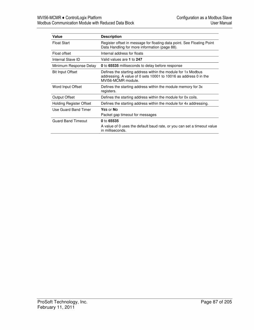
MVI56-MCMR ♦ ControlLogix Platform Configuration as a Modbus Slave Modbus Communication Module with Reduced Data Block User Manual
ProSoft Technology, Inc. Page 87 of 205 February 11, 2011
Value Description
Float Start Register offset in message for floating data point. See Floating Point Data Handling for more information (page 88).
Float offset Internal address for floats
Internal Slave ID Valid values are 1 to 247
Minimum Response Delay 0 to 65535 milliseconds to delay before response
Bit Input Offset Defines the starting address within the module for 1x Modbus addressing. A value of 0 sets 10001 to 10016 as address 0 in the MVI56-MCMR module.
Word Input Offset Defines the starting address within the module memory for 3x registers.
Output Offset Defines the starting address within the module for 0x coils.
Holding Register Offset Defines the starting address within the module for 4x addressing.
Use Guard Band Timer YES or NO Packet gap timeout for messages
Guard Band Timeout 0 to 65535 A value of 0 uses the default baud rate, or you can set a timeout value in milliseconds.
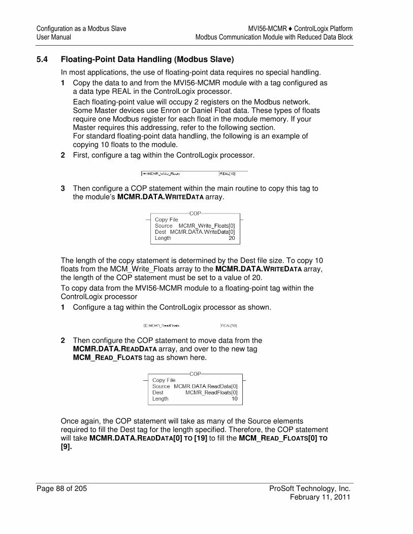
Configuration as a Modbus Slave MVI56-MCMR ♦ ControlLogix Platform User Manual Modbus Communication Module with Reduced Data Block
Page 88 of 205 ProSoft Technology, Inc. February 11, 2011
5.4 Floating-Point Data Handling (Modbus Slave)
In most applications, the use of floating-point data requires no special handling. 1 Copy the data to and from the MVI56-MCMR module with a tag configured as
a data type REAL in the ControlLogix processor. Each floating-point value will occupy 2 registers on the Modbus network. Some Master devices use Enron or Daniel Float data. These types of floats require one Modbus register for each float in the module memory. If your Master requires this addressing, refer to the following section. For standard floating-point data handling, the following is an example of copying 10 floats to the module.
2 First, configure a tag within the ControlLogix processor.
3 Then configure a COP statement within the main routine to copy this tag to the module’s MCMR.DATA.WRITEDATA array.
The length of the copy statement is determined by the Dest file size. To copy 10 floats from the MCM_Write_Floats array to the MCMR.DATA.WRITEDATA array, the length of the COP statement must be set to a value of 20. To copy data from the MVI56-MCMR module to a floating-point tag within the ControlLogix processor 1 Configure a tag within the ControlLogix processor as shown.
2 Then configure the COP statement to move data from the MCMR.DATA.READDATA array, and over to the new tag MCM_READ_FLOATS tag as shown here.
Once again, the COP statement will take as many of the Source elements required to fill the Dest tag for the length specified. Therefore, the COP statement will take MCMR.DATA.READDATA[0] TO [19] to fill the MCM_READ_FLOATS[0] TO
[9].
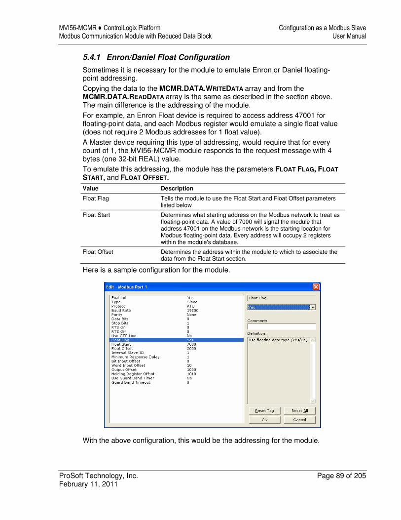
MVI56-MCMR ♦ ControlLogix Platform Configuration as a Modbus Slave Modbus Communication Module with Reduced Data Block User Manual
ProSoft Technology, Inc. Page 89 of 205 February 11, 2011
5.4.1 Enron/Daniel Float Configuration
Sometimes it is necessary for the module to emulate Enron or Daniel floating-point addressing. Copying the data to the MCMR.DATA.WRITEDATA array and from the MCMR.DATA.READDATA array is the same as described in the section above. The main difference is the addressing of the module. For example, an Enron Float device is required to access address 47001 for floating-point data, and each Modbus register would emulate a single float value (does not require 2 Modbus addresses for 1 float value). A Master device requiring this type of addressing, would require that for every count of 1, the MVI56-MCMR module responds to the request message with 4 bytes (one 32-bit REAL) value. To emulate this addressing, the module has the parameters FLOAT FLAG, FLOAT
START, and FLOAT OFFSET.
Value Description
Float Flag Tells the module to use the Float Start and Float Offset parameters listed below
Float Start Determines what starting address on the Modbus network to treat as floating-point data. A value of 7000 will signal the module that address 47001 on the Modbus network is the starting location for Modbus floating-point data. Every address will occupy 2 registers within the module's database.
Float Offset Determines the address within the module to which to associate the data from the Float Start section.
Here is a sample configuration for the module.
With the above configuration, this would be the addressing for the module.
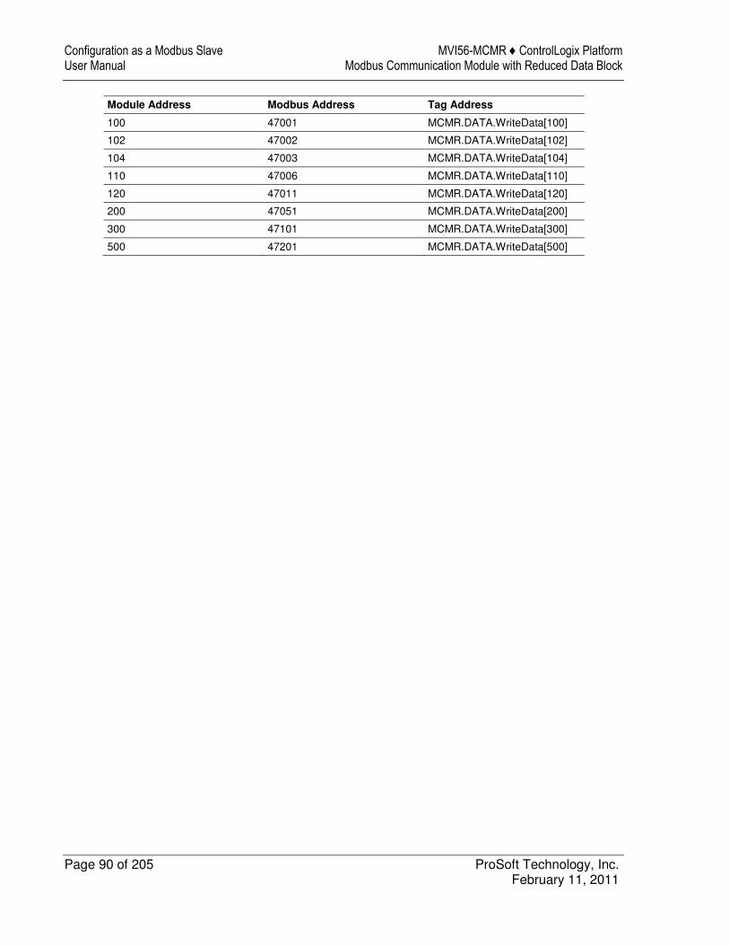
Configuration as a Modbus Slave MVI56-MCMR ♦ ControlLogix Platform User Manual Modbus Communication Module with Reduced Data Block
Page 90 of 205 ProSoft Technology, Inc. February 11, 2011
Module Address Modbus Address Tag Address
100 47001 MCMR.DATA.WriteData[100]
102 47002 MCMR.DATA.WriteData[102]
104 47003 MCMR.DATA.WriteData[104]
110 47006 MCMR.DATA.WriteData[110]
120 47011 MCMR.DATA.WriteData[120]
200 47051 MCMR.DATA.WriteData[200]
300 47101 MCMR.DATA.WriteData[300]
500 47201 MCMR.DATA.WriteData[500]
MVI56-MCMR ♦ ControlLogix Platform Verify Communication Modbus Communication Module with Reduced Data Block User Manual
ProSoft Technology, Inc. Page 91 of 205 February 11, 2011
6 Verify Communication
In This Chapter
� Verify Master Communications .............................................................. 92
� Verify Slave Communications ................................................................ 99
There are several ways to verify that the MVI56-MCMR module is communicating with the processor and with the Modbus network. � View the LED Status Indicators � View the Module Status in the RSLogix 5000 Controller Tags � View Diagnostics in ProSoft Configuration Builder (page 111)
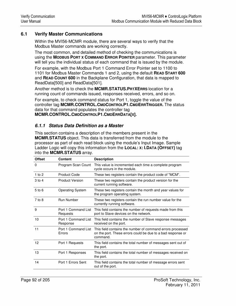
Verify Communication MVI56-MCMR ♦ ControlLogix Platform User Manual Modbus Communication Module with Reduced Data Block
Page 92 of 205 ProSoft Technology, Inc. February 11, 2011
6.1 Verify Master Communications
Within the MVI56-MCMR module, there are several ways to verify that the Modbus Master commands are working correctly. The most common, and detailed method of checking the communications is using the MODBUS PORT X COMMAND ERROR POINTER parameter. This parameter will tell you the individual status of each command that is issued by the module. For example, with the Modbus Port 1 Command Error Pointer set to 1100 to 1101 for Modbus Master Commands 1 and 2, using the default READ START 600 and READ COUNT 600 in the Backplane Configuration, that data is mapped to ReadData[500] and ReadData[501]. Another method is to check the MCMR.STATUS.PRTXERRS location for a running count of commands issued, responses received, errors, and so on. For example, to check command status for Port 1, toggle the value of the controller tag MCMR.CONTROL.CMDCONTROLP1.CMDERRTRIGGER. The status data for that command populates the controller tag MCMR.CONTROL.CMDCONTROLP1.CMDERRDATA[X].
6.1.1 Status Data Definition as a Master
This section contains a description of the members present in the MCMR.STATUS object. This data is transferred from the module to the processor as part of each read block using the module’s Input Image. Sample Ladder Logic will copy this information from the LOCAL: X: I.DATA {OFFSET} tag into the MCMR.STATUS array.
Offset Content Description
0 Program Scan Count This value is incremented each time a complete program cycle occurs in the module.
1 to 2 Product Code These two registers contain the product code of "MCM".
3 to 4 Product Version These two registers contain the product version for the current running software.
5 to 6 Operating System These two registers contain the month and year values for the program operating system.
7 to 8 Run Number These two registers contain the run number value for the currently running software.
9 Port 1 Command List Requests
This field contains the number of requests made from this port to Slave devices on the network.
10 Port 1 Command List Response
This field contains the number of Slave response messages received on the port.
11 Port 1 Command List Errors
This field contains the number of command errors processed on the port. These errors could be due to a bad response or command.
12 Port 1 Requests This field contains the total number of messages sent out of the port.
13 Port 1 Responses This field contains the total number of messages received on the port.
14 Port 1 Errors Sent This field contains the total number of message errors sent out of the port.
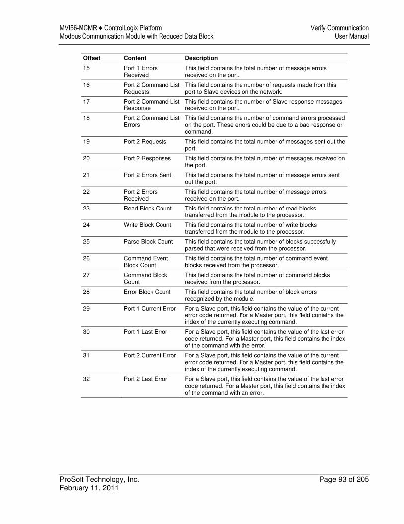
MVI56-MCMR ♦ ControlLogix Platform Verify Communication Modbus Communication Module with Reduced Data Block User Manual
ProSoft Technology, Inc. Page 93 of 205 February 11, 2011
Offset Content Description
15 Port 1 Errors Received
This field contains the total number of message errors received on the port.
16 Port 2 Command List Requests
This field contains the number of requests made from this port to Slave devices on the network.
17 Port 2 Command List Response
This field contains the number of Slave response messages received on the port.
18 Port 2 Command List Errors
This field contains the number of command errors processed on the port. These errors could be due to a bad response or command.
19 Port 2 Requests This field contains the total number of messages sent out the port.
20 Port 2 Responses This field contains the total number of messages received on the port.
21 Port 2 Errors Sent This field contains the total number of message errors sent out the port.
22 Port 2 Errors Received
This field contains the total number of message errors received on the port.
23 Read Block Count This field contains the total number of read blocks transferred from the module to the processor.
24 Write Block Count This field contains the total number of write blocks transferred from the module to the processor.
25 Parse Block Count This field contains the total number of blocks successfully parsed that were received from the processor.
26 Command Event Block Count
This field contains the total number of command event blocks received from the processor.
27 Command Block Count
This field contains the total number of command blocks received from the processor.
28 Error Block Count This field contains the total number of block errors recognized by the module.
29 Port 1 Current Error For a Slave port, this field contains the value of the current error code returned. For a Master port, this field contains the index of the currently executing command.
30 Port 1 Last Error For a Slave port, this field contains the value of the last error code returned. For a Master port, this field contains the index of the command with the error.
31 Port 2 Current Error For a Slave port, this field contains the value of the current error code returned. For a Master port, this field contains the index of the currently executing command.
32 Port 2 Last Error For a Slave port, this field contains the value of the last error code returned. For a Master port, this field contains the index of the command with an error.
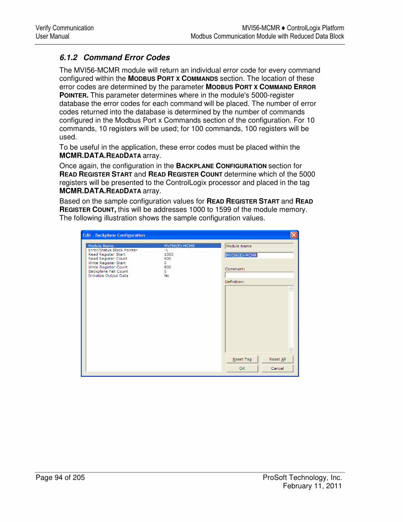
Verify Communication MVI56-MCMR ♦ ControlLogix Platform User Manual Modbus Communication Module with Reduced Data Block
Page 94 of 205 ProSoft Technology, Inc. February 11, 2011
6.1.2 Command Error Codes
The MVI56-MCMR module will return an individual error code for every command configured within the MODBUS PORT X COMMANDS section. The location of these error codes are determined by the parameter MODBUS PORT X COMMAND ERROR
POINTER. This parameter determines where in the module's 5000-register database the error codes for each command will be placed. The number of error codes returned into the database is determined by the number of commands configured in the Modbus Port x Commands section of the configuration. For 10 commands, 10 registers will be used; for 100 commands, 100 registers will be used. To be useful in the application, these error codes must be placed within the MCMR.DATA.READDATA array. Once again, the configuration in the BACKPLANE CONFIGURATION section for READ REGISTER START and READ REGISTER COUNT determine which of the 5000 registers will be presented to the ControlLogix processor and placed in the tag MCMR.DATA.READDATA array. Based on the sample configuration values for READ REGISTER START and READ
REGISTER COUNT, this will be addresses 1000 to 1599 of the module memory. The following illustration shows the sample configuration values.
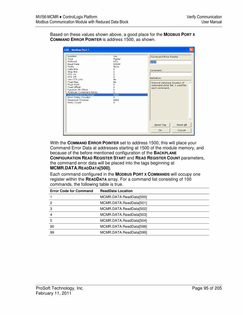
MVI56-MCMR ♦ ControlLogix Platform Verify Communication Modbus Communication Module with Reduced Data Block User Manual
ProSoft Technology, Inc. Page 95 of 205 February 11, 2011
Based on these values shown above, a good place for the MODBUS PORT X
COMMAND ERROR POINTER is address 1500, as shown.
With the COMMAND ERROR POINTER set to address 1500, this will place your Command Error Data at addresses starting at 1500 of the module memory, and because of the before mentioned configuration of the BACKPLANE
CONFIGURATION READ REGISTER START and READ REGISTER COUNT parameters, the command error data will be placed into the tags beginning at MCMR.DATA.READDATA[500]. Each command configured in the MODBUS PORT X COMMANDS will occupy one register within the READDATA array. For a command list consisting of 100 commands, the following table is true. Error Code for Command ReadData Location
1 MCMR.DATA.ReadData[500]
2 MCMR.DATA.ReadData[501]
3 MCMR.DATA.ReadData[502]
4 MCMR.DATA.ReadData[503]
5 MCMR.DATA.ReadData[504]
90 MCMR.DATA.ReadData[598]
99 MCMR.DATA.ReadData[599]
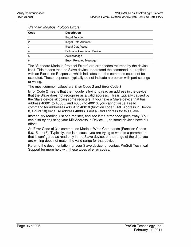
Verify Communication MVI56-MCMR ♦ ControlLogix Platform User Manual Modbus Communication Module with Reduced Data Block
Page 96 of 205 ProSoft Technology, Inc. February 11, 2011
Standard Modbus Protocol Errors
Code Description
1 Illegal Function
2 Illegal Data Address
3 Illegal Data Value
4 Failure in Associated Device
5 Acknowledge
6 Busy, Rejected Message
The "Standard Modbus Protocol Errors" are error codes returned by the device itself. This means that the Slave device understood the command, but replied with an Exception Response, which indicates that the command could not be executed. These responses typically do not indicate a problem with port settings or wiring. The most common values are Error Code 2 and Error Code 3. Error Code 2 means that the module is trying to read an address in the device that the Slave does not recognize as a valid address. This is typically caused by the Slave device skipping some registers. If you have a Slave device that has address 40001 to 40005, and 40007 to 40010, you cannot issue a read command for addresses 40001 to 40010 (function code 3, MB Address in Device 0, Count 10) because address 40006 is not a valid address for this Slave. Instead, try reading just one register, and see if the error code goes away. You can also try adjusting your MB Address in Device -1, as some devices have a 1 offset. An Error Code of 3 is common on Modbus Write Commands (Function Codes 5,6,15, or 16). Typically, this is because you are trying to write to a parameter that is configured as read only in the Slave device, or the range of the data you are writing does not match the valid range for that device. Refer to the documentation for your Slave device, or contact ProSoft Technical Support for more help with these types of error codes.
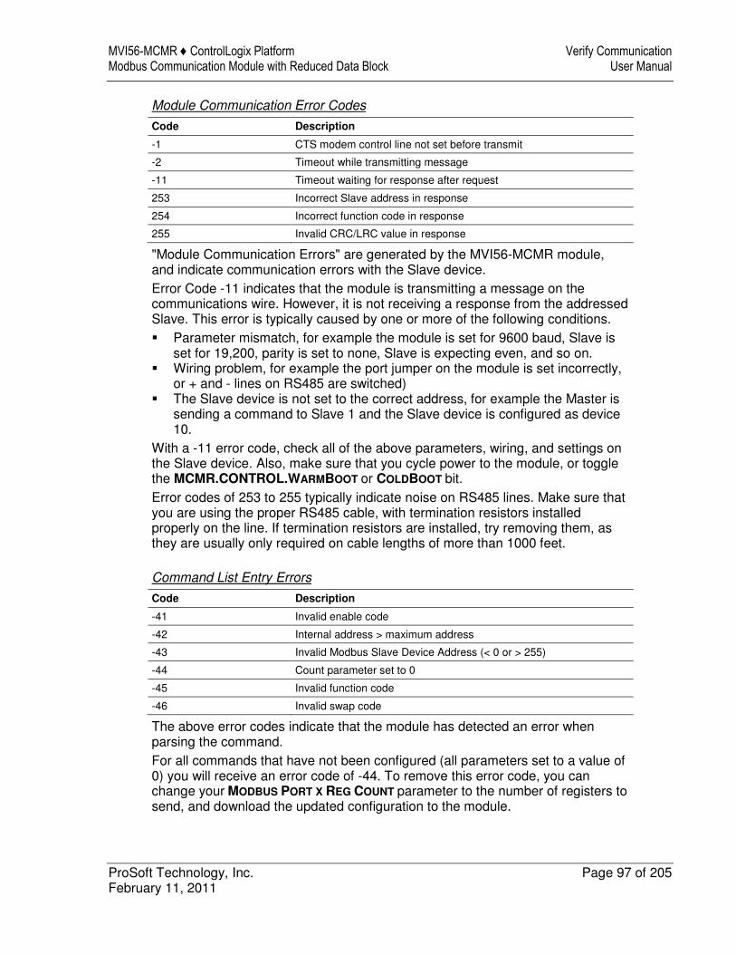
MVI56-MCMR ♦ ControlLogix Platform Verify Communication Modbus Communication Module with Reduced Data Block User Manual
ProSoft Technology, Inc. Page 97 of 205 February 11, 2011
Module Communication Error Codes
Code Description
-1 CTS modem control line not set before transmit
-2 Timeout while transmitting message
-11 Timeout waiting for response after request
253 Incorrect Slave address in response
254 Incorrect function code in response
255 Invalid CRC/LRC value in response
"Module Communication Errors" are generated by the MVI56-MCMR module, and indicate communication errors with the Slave device. Error Code -11 indicates that the module is transmitting a message on the communications wire. However, it is not receiving a response from the addressed Slave. This error is typically caused by one or more of the following conditions. � Parameter mismatch, for example the module is set for 9600 baud, Slave is
set for 19,200, parity is set to none, Slave is expecting even, and so on. � Wiring problem, for example the port jumper on the module is set incorrectly,
or + and - lines on RS485 are switched) � The Slave device is not set to the correct address, for example the Master is
sending a command to Slave 1 and the Slave device is configured as device 10.
With a -11 error code, check all of the above parameters, wiring, and settings on the Slave device. Also, make sure that you cycle power to the module, or toggle the MCMR.CONTROL.WARMBOOT or COLDBOOT bit. Error codes of 253 to 255 typically indicate noise on RS485 lines. Make sure that you are using the proper RS485 cable, with termination resistors installed properly on the line. If termination resistors are installed, try removing them, as they are usually only required on cable lengths of more than 1000 feet.
Command List Entry Errors
Code Description
-41 Invalid enable code
-42 Internal address > maximum address
-43 Invalid Modbus Slave Device Address (< 0 or > 255)
-44 Count parameter set to 0
-45 Invalid function code
-46 Invalid swap code
The above error codes indicate that the module has detected an error when parsing the command. For all commands that have not been configured (all parameters set to a value of 0) you will receive an error code of -44. To remove this error code, you can change your MODBUS PORT X REG COUNT parameter to the number of registers to send, and download the updated configuration to the module.
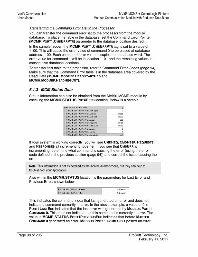
Verify Communication MVI56-MCMR ♦ ControlLogix Platform User Manual Modbus Communication Module with Reduced Data Block
Page 98 of 205 ProSoft Technology, Inc. February 11, 2011
Transferring the Command Error List to the Processor
You can transfer the command error list to the processor from the module database. To place the table in the database, set the Command Error Pointer (MCMR.PORT1.CMDERRPTR) parameter to the database location desired. In the sample ladder, the MCMR.PORT1.CMDERRPTR tag is set to a value of 1100. This will cause the error value of command 0 to be placed at database address 1100. Each command error value occupies one database word. The error value for command 1 will be in location 1101 and the remaining values in consecutive database locations. To transfer this table to the processor, refer to Command Error Codes (page 94). Make sure that the Command Error table is in the database area covered by the Read Data (MCMR.MODDEF.READSTARTREG and MCMR.MODDEF.READREGCNT).
6.1.3 MCM Status Data
Status information can also be obtained from the MVI56-MCMR module by checking the MCMR.STATUS.PRTXERRS location. Below is a sample.
If your system is working correctly, you will see CMDREQ, CMDRESP, REQUESTS, and RESPONSES all incrementing together. If you see that CMDERR is incrementing, determine what command is causing the error (using the error code defined in the previous section (page 94)) and correct the issue causing the error.
Note: This information is not as detailed as the individual error codes, but they can help to troubleshoot your application.
Also within the MCMR.STATUS location is the parameters for Last Error and Previous Error, shown below.
This indicates the command index that last generated an error and does not indicate a command currently in error. In the above example, a value of 0 in PORT1LASTERR indicates that the last error was generated by MODBUS PORT 1
COMMAND 0. This does not indicate that this command is currently in error. The value in MCMR.STATUS.PORT1PREVIOUSERR indicates that before MASTER
COMMAND 0 generated an error, MODBUS PORT 1 COMMAND 1 posted an error.
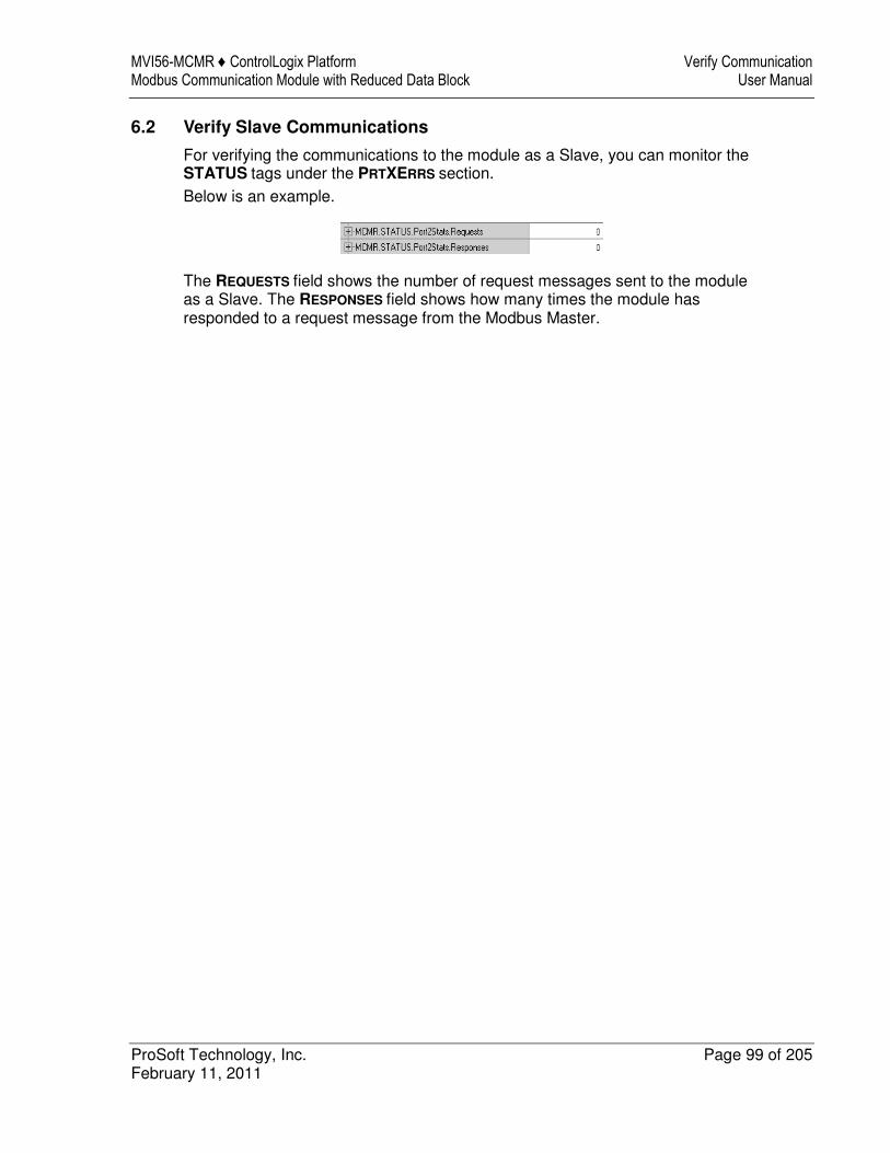
MVI56-MCMR ♦ ControlLogix Platform Verify Communication Modbus Communication Module with Reduced Data Block User Manual
ProSoft Technology, Inc. Page 99 of 205 February 11, 2011
6.2 Verify Slave Communications
For verifying the communications to the module as a Slave, you can monitor the STATUS tags under the PRTXERRS section. Below is an example.
The REQUESTS field shows the number of request messages sent to the module as a Slave. The RESPONSES field shows how many times the module has responded to a request message from the Modbus Master.
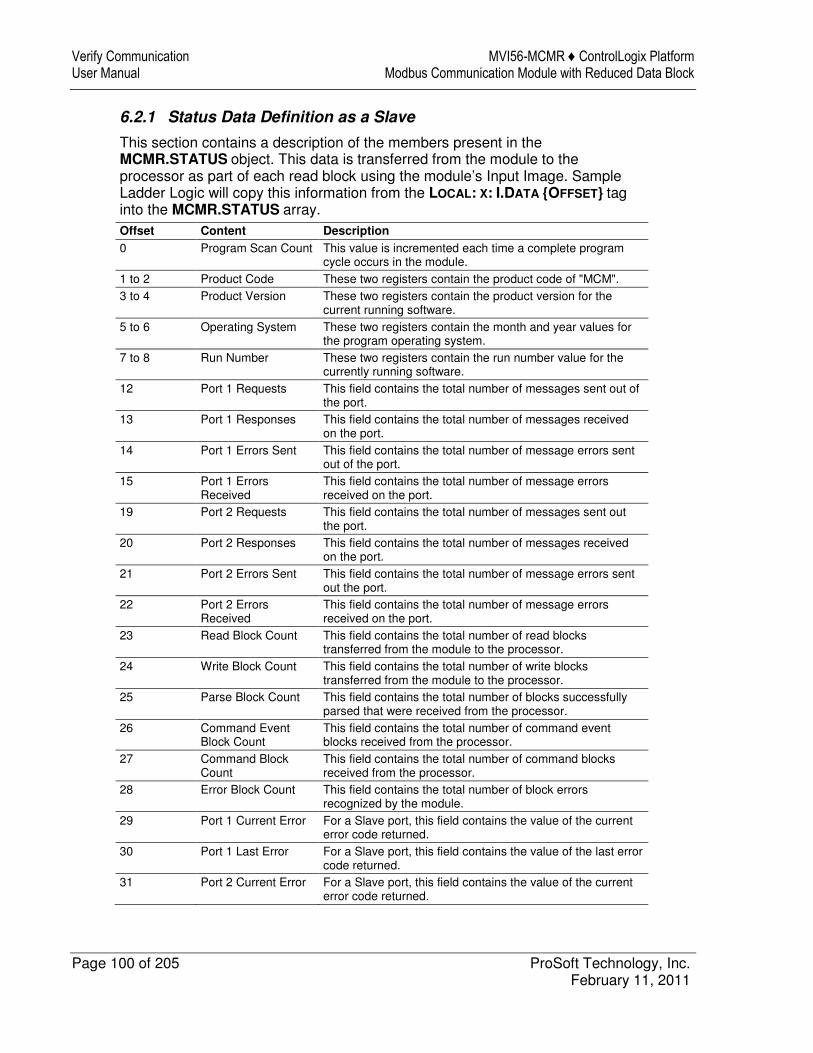
Verify Communication MVI56-MCMR ♦ ControlLogix Platform User Manual Modbus Communication Module with Reduced Data Block
Page 100 of 205 ProSoft Technology, Inc. February 11, 2011
6.2.1 Status Data Definition as a Slave
This section contains a description of the members present in the MCMR.STATUS object. This data is transferred from the module to the processor as part of each read block using the module’s Input Image. Sample Ladder Logic will copy this information from the LOCAL: X: I.DATA {OFFSET} tag into the MCMR.STATUS array. Offset Content Description
0 Program Scan Count This value is incremented each time a complete program cycle occurs in the module.
1 to 2 Product Code These two registers contain the product code of "MCM". 3 to 4 Product Version These two registers contain the product version for the
current running software. 5 to 6 Operating System These two registers contain the month and year values for
the program operating system. 7 to 8 Run Number These two registers contain the run number value for the
currently running software. 12 Port 1 Requests This field contains the total number of messages sent out of
the port. 13 Port 1 Responses This field contains the total number of messages received
on the port. 14 Port 1 Errors Sent This field contains the total number of message errors sent
out of the port. 15 Port 1 Errors
Received This field contains the total number of message errors received on the port.
19 Port 2 Requests This field contains the total number of messages sent out the port.
20 Port 2 Responses This field contains the total number of messages received on the port.
21 Port 2 Errors Sent This field contains the total number of message errors sent out the port.
22 Port 2 Errors Received
This field contains the total number of message errors received on the port.
23 Read Block Count This field contains the total number of read blocks transferred from the module to the processor.
24 Write Block Count This field contains the total number of write blocks transferred from the module to the processor.
25 Parse Block Count This field contains the total number of blocks successfully parsed that were received from the processor.
26 Command Event Block Count
This field contains the total number of command event blocks received from the processor.
27 Command Block Count
This field contains the total number of command blocks received from the processor.
28 Error Block Count This field contains the total number of block errors recognized by the module.
29 Port 1 Current Error For a Slave port, this field contains the value of the current error code returned.
30 Port 1 Last Error For a Slave port, this field contains the value of the last error code returned.
31 Port 2 Current Error For a Slave port, this field contains the value of the current error code returned.

MVI56-MCMR ♦ ControlLogix Platform Verify Communication Modbus Communication Module with Reduced Data Block User Manual
ProSoft Technology, Inc. Page 101 of 205 February 11, 2011
Offset Content Description
32 Port 2 Last Error For a Slave port, this field contains the value of the last error code returned.

Verify Communication MVI56-MCMR ♦ ControlLogix Platform User Manual Modbus Communication Module with Reduced Data Block
Page 102 of 205 ProSoft Technology, Inc. February 11, 2011
MVI56-MCMR ♦ ControlLogix Platform Ladder Logic Modbus Communication Module with Reduced Data Block User Manual
ProSoft Technology, Inc. Page 103 of 205 February 11, 2011
7 Ladder Logic
In This Chapter
� MVI56-MCMR User Defined Data Types............................................. 104
Ladder logic is required for application of the MVI56-MCMR module. Tasks that must be handled by the ladder logic are module data transfer, special block handling, and status data receipt. Additionally, a power-up handler may be needed to handle the initialization of the module’s data and to clear any processor fault conditions. The sample ladder logic, on the ProSoft Solutions CD-ROM, is extensively commented, to provide information on the purpose and function of each rung. For most applications, the sample ladder will work without modification.
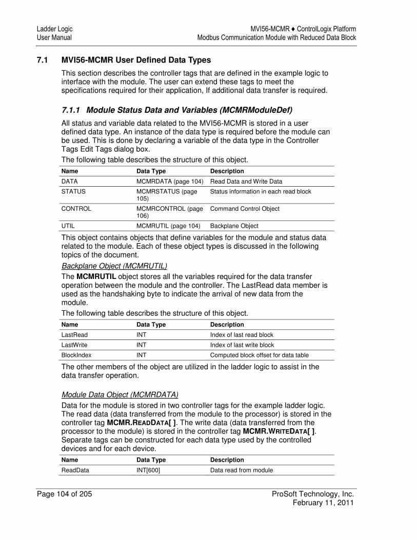
Ladder Logic MVI56-MCMR ♦ ControlLogix Platform User Manual Modbus Communication Module with Reduced Data Block
Page 104 of 205 ProSoft Technology, Inc. February 11, 2011
7.1 MVI56-MCMR User Defined Data Types
This section describes the controller tags that are defined in the example logic to interface with the module. The user can extend these tags to meet the specifications required for their application, If additional data transfer is required.
7.1.1 Module Status Data and Variables (MCMRModuleDef)
All status and variable data related to the MVI56-MCMR is stored in a user defined data type. An instance of the data type is required before the module can be used. This is done by declaring a variable of the data type in the Controller Tags Edit Tags dialog box. The following table describes the structure of this object.
Name Data Type Description
DATA MCMRDATA (page 104) Read Data and Write Data
STATUS MCMRSTATUS (page 105)
Status information in each read block
CONTROL MCMRCONTROL (page 106)
Command Control Object
UTIL MCMRUTIL (page 104) Backplane Object
This object contains objects that define variables for the module and status data related to the module. Each of these object types is discussed in the following topics of the document.
Backplane Object (MCMRUTIL)
The MCMRUTIL object stores all the variables required for the data transfer operation between the module and the controller. The LastRead data member is used as the handshaking byte to indicate the arrival of new data from the module. The following table describes the structure of this object.
Name Data Type Description
LastRead INT Index of last read block
LastWrite INT Index of last write block
BlockIndex INT Computed block offset for data table
The other members of the object are utilized in the ladder logic to assist in the data transfer operation.
Module Data Object (MCMRDATA)
Data for the module is stored in two controller tags for the example ladder logic. The read data (data transferred from the module to the processor) is stored in the controller tag MCMR.READDATA[ ]. The write data (data transferred from the processor to the module) is stored in the controller tag MCMR.WRITEDATA[ ]. Separate tags can be constructed for each data type used by the controlled devices and for each device. Name Data Type Description
ReadData INT[600] Data read from module
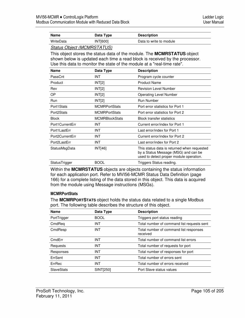
MVI56-MCMR ♦ ControlLogix Platform Ladder Logic Modbus Communication Module with Reduced Data Block User Manual
ProSoft Technology, Inc. Page 105 of 205 February 11, 2011
Name Data Type Description
WriteData INT[600] Data to write to module
Status Object (MCMRSTATUS)
This object stores the status data of the module. The MCMRSTATUS object shown below is updated each time a read block is received by the processor. Use this data to monitor the state of the module at a "real-time rate".
Name Data Type Description
PassCnt INT Program cycle counter
Product INT[2] Product Name
Rev INT[2] Revision Level Number
OP INT[2] Operating Level Number
Run INT[2] Run Number
Port1Stats MCMRPortStats Port error statistics for Port 1
Port2Stats MCMRPortStats Port error statistics for Port 2
Block MCMRBlockStats Block transfer statistics
Port1CurrentErr INT Current error/index for Port 1
Port1LastErr INT Last error/index for Port 1
Port2CurrentErr INT Current error/index for Port 2
Port2LastErr INT Last error/index for Port 2
StatusMsgData INT[46] This status data is returned when requested by a Status Message (MSG) and can be used to detect proper module operation.
StatusTrigger BOOL Triggers Status reading.
Within the MCMRSTATUS objects are objects containing the status information for each application port. Refer to MVI56-MCMR Status Data Definition (page 166) for a complete listing of the data stored in this object. This data is acquired from the module using Message instructions (MSGs).
MCMRPortStats
The MCMRPORTSTATS object holds the status data related to a single Modbus port. The following table describes the structure of this object. Name Data Type Description
PortTrigger BOOL Triggers port status reading
CmdReq INT Total number of command list requests sent
CmdResp INT Total number of command list responses received
CmdErr INT Total number of command list errors
Requests INT Total number of requests for port
Responses INT Total number of responses for port
ErrSent INT Total number of errors sent
ErrRec INT Total number of errors received
SlaveStats SINT[250] Port Slave status values
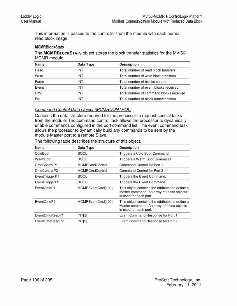
Ladder Logic MVI56-MCMR ♦ ControlLogix Platform User Manual Modbus Communication Module with Reduced Data Block
Page 106 of 205 ProSoft Technology, Inc. February 11, 2011
This information is passed to the controller from the module with each normal read block image.
MCMRBlockStats
The MCMRBLOCKSTATS object stores the block transfer statistics for the MVI56-MCMR module.
Name Data Type Description
Read INT Total number of read block transfers
Write INT Total number of write block transfers
Parse INT Total number of blocks parsed
Event INT Total number of event blocks received
Cmd INT Total number of command blocks received
Err INT Total number of block transfer errors
Command Control Data Object (MCMRCONTROL)
Contains the data structure required for the processor to request special tasks from the module. The command control task allows the processor to dynamically enable commands configured in the port command list. The event command task allows the processor to dynamically build any commands to be sent by the module Master port to a remote Slave. The following table describes the structure of this object. Name Data Type Description
ColdBoot BOOL Triggers a Cold Boot Command
WarmBoot BOOL Triggers a Warm Boot Command
CmdControlP1 MCMRCmdControl Command Control for Port 1
CmdControlP2 MCMRCmdControl Command Control for Port 2
EventTriggerP1 BOOL Triggers the Event Command.
EventTriggerP2 BOOL Triggers the Event Command.
EventCmdP1 MCMREventCmd[100] This object contains the attributes to define a Master command. An array of these objects is used for each port.
EventCmdP2 MCMREventCmd[100] This object contains the attributes to define a Master command. An array of these objects is used for each port.
EventCmdRespP1 INT[5] Event Command Response for Port 1
EventCmdRespP2 INT[5] Event Command Response for Port 2
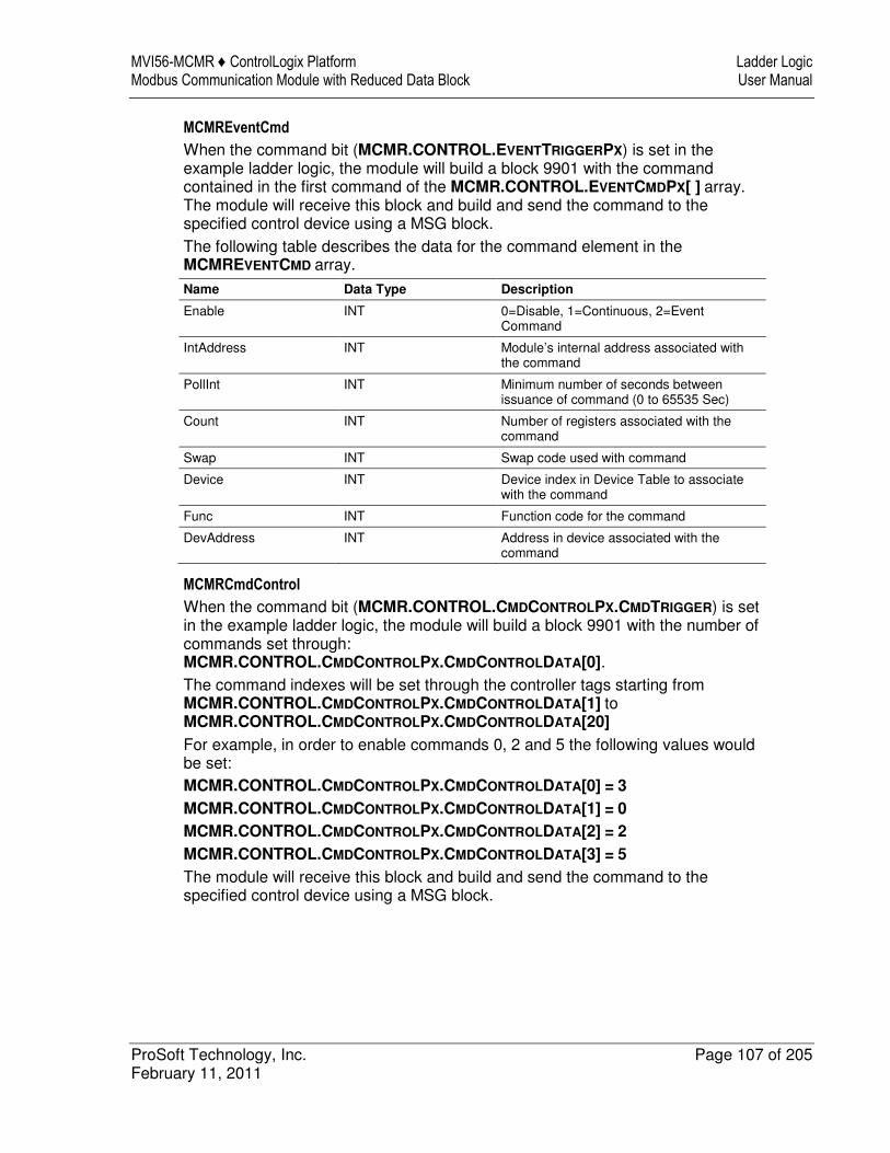
MVI56-MCMR ♦ ControlLogix Platform Ladder Logic Modbus Communication Module with Reduced Data Block User Manual
ProSoft Technology, Inc. Page 107 of 205 February 11, 2011
MCMREventCmd
When the command bit (MCMR.CONTROL.EVENTTRIGGERPX) is set in the example ladder logic, the module will build a block 9901 with the command contained in the first command of the MCMR.CONTROL.EVENTCMDPX[ ] array. The module will receive this block and build and send the command to the specified control device using a MSG block. The following table describes the data for the command element in the MCMREVENTCMD array.
Name Data Type Description
Enable INT 0=Disable, 1=Continuous, 2=Event Command
IntAddress INT Module’s internal address associated with the command
PollInt INT Minimum number of seconds between issuance of command (0 to 65535 Sec)
Count INT Number of registers associated with the command
Swap INT Swap code used with command
Device INT Device index in Device Table to associate with the command
Func INT Function code for the command
DevAddress INT Address in device associated with the command
MCMRCmdControl
When the command bit (MCMR.CONTROL.CMDCONTROLPX.CMDTRIGGER) is set in the example ladder logic, the module will build a block 9901 with the number of commands set through: MCMR.CONTROL.CMDCONTROLPX.CMDCONTROLDATA[0]. The command indexes will be set through the controller tags starting from MCMR.CONTROL.CMDCONTROLPX.CMDCONTROLDATA[1] to MCMR.CONTROL.CMDCONTROLPX.CMDCONTROLDATA[20] For example, in order to enable commands 0, 2 and 5 the following values would be set: MCMR.CONTROL.CMDCONTROLPX.CMDCONTROLDATA[0] = 3 MCMR.CONTROL.CMDCONTROLPX.CMDCONTROLDATA[1] = 0 MCMR.CONTROL.CMDCONTROLPX.CMDCONTROLDATA[2] = 2 MCMR.CONTROL.CMDCONTROLPX.CMDCONTROLDATA[3] = 5 The module will receive this block and build and send the command to the specified control device using a MSG block.
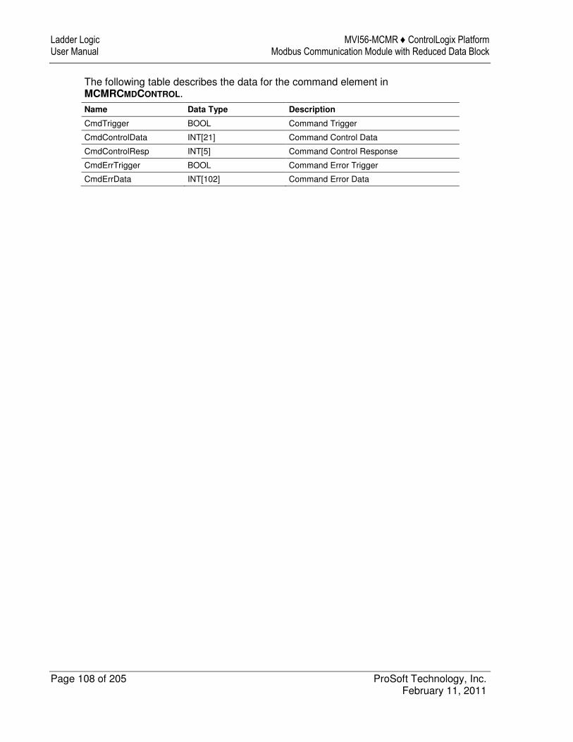
Ladder Logic MVI56-MCMR ♦ ControlLogix Platform User Manual Modbus Communication Module with Reduced Data Block
Page 108 of 205 ProSoft Technology, Inc. February 11, 2011
The following table describes the data for the command element in MCMRCMDCONTROL.
Name Data Type Description
CmdTrigger BOOL Command Trigger
CmdControlData INT[21] Command Control Data
CmdControlResp INT[5] Command Control Response
CmdErrTrigger BOOL Command Error Trigger
CmdErrData INT[102] Command Error Data
MVI56-MCMR ♦ ControlLogix Platform Diagnostics and Troubleshooting Modbus Communication Module with Reduced Data Block User Manual
ProSoft Technology, Inc. Page 109 of 205 February 11, 2011
8 Diagnostics and Troubleshooting
In This Chapter
� LED Status Indicators .......................................................................... 110
� Using ProSoft Configuration Builder (PCB) for Diagnostics................. 111
� Reading Status Data from the Module ................................................ 128
� Communication Error Codes ............................................................... 129
The module provides information on diagnostics and troubleshooting in the following forms: � LED status indicators on the front of the module provide general information
on the module's status. � Status data contained in the module can be viewed through the
Configuration/Debug port, using the troubleshooting and diagnostic capabilities of ProSoft Configuration Builder (PCB).
� Status data values can be transferred from the module to processor memory and can be monitored there manually or by customer-created logic.
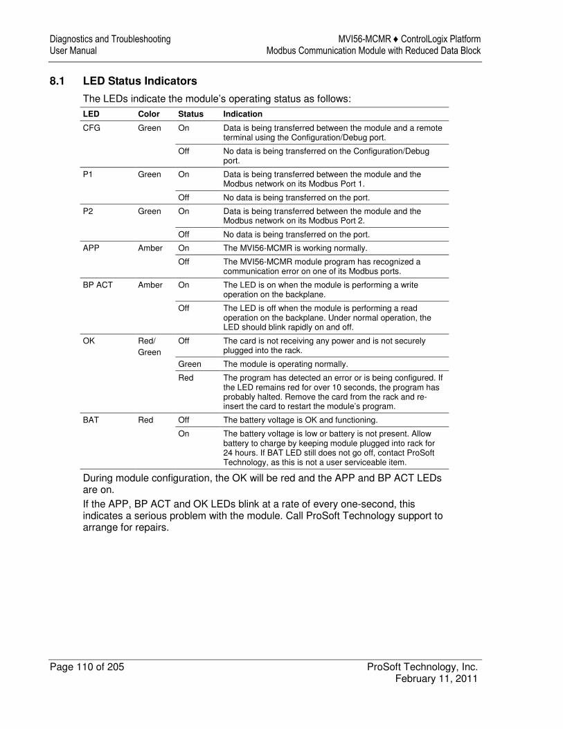
Diagnostics and Troubleshooting MVI56-MCMR ♦ ControlLogix Platform User Manual Modbus Communication Module with Reduced Data Block
Page 110 of 205 ProSoft Technology, Inc. February 11, 2011
8.1 LED Status Indicators
The LEDs indicate the module’s operating status as follows: LED Color Status Indication
CFG Green On Data is being transferred between the module and a remote terminal using the Configuration/Debug port.
Off No data is being transferred on the Configuration/Debug port.
P1 Green On Data is being transferred between the module and the Modbus network on its Modbus Port 1.
Off No data is being transferred on the port.
P2 Green On Data is being transferred between the module and the Modbus network on its Modbus Port 2.
Off No data is being transferred on the port.
APP Amber On The MVI56-MCMR is working normally.
Off The MVI56-MCMR module program has recognized a communication error on one of its Modbus ports.
BP ACT Amber On The LED is on when the module is performing a write operation on the backplane.
Off The LED is off when the module is performing a read operation on the backplane. Under normal operation, the LED should blink rapidly on and off.
OK Red/ Green
Off The card is not receiving any power and is not securely plugged into the rack.
Green The module is operating normally.
Red The program has detected an error or is being configured. If the LED remains red for over 10 seconds, the program has probably halted. Remove the card from the rack and re-insert the card to restart the module’s program.
BAT Red Off The battery voltage is OK and functioning.
On The battery voltage is low or battery is not present. Allow battery to charge by keeping module plugged into rack for 24 hours. If BAT LED still does not go off, contact ProSoft Technology, as this is not a user serviceable item.
During module configuration, the OK will be red and the APP and BP ACT LEDs are on. If the APP, BP ACT and OK LEDs blink at a rate of every one-second, this indicates a serious problem with the module. Call ProSoft Technology support to arrange for repairs.
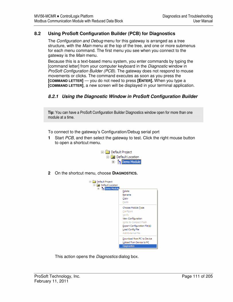
MVI56-MCMR ♦ ControlLogix Platform Diagnostics and Troubleshooting Modbus Communication Module with Reduced Data Block User Manual
ProSoft Technology, Inc. Page 111 of 205 February 11, 2011
8.2 Using ProSoft Configuration Builder (PCB) for Diagnostics
The Configuration and Debug menu for this gateway is arranged as a tree structure, with the Main menu at the top of the tree, and one or more submenus for each menu command. The first menu you see when you connect to the gateway is the Main menu. Because this is a text-based menu system, you enter commands by typing the [command letter] from your computer keyboard in the Diagnostic window in ProSoft Configuration Builder (PCB). The gateway does not respond to mouse movements or clicks. The command executes as soon as you press the
[COMMAND LETTER] — you do not need to press [ENTER]. When you type a
[COMMAND LETTER], a new screen will be displayed in your terminal application.
8.2.1 Using the Diagnostic Window in ProSoft Configuration Builder
Tip: You can have a ProSoft Configuration Builder Diagnostics window open for more than one module at a time.
To connect to the gateway’s Configuration/Debug serial port 1 Start PCB, and then select the gateway to test. Click the right mouse button
to open a shortcut menu.
2 On the shortcut menu, choose DIAGNOSTICS.
This action opens the Diagnostics dialog box.
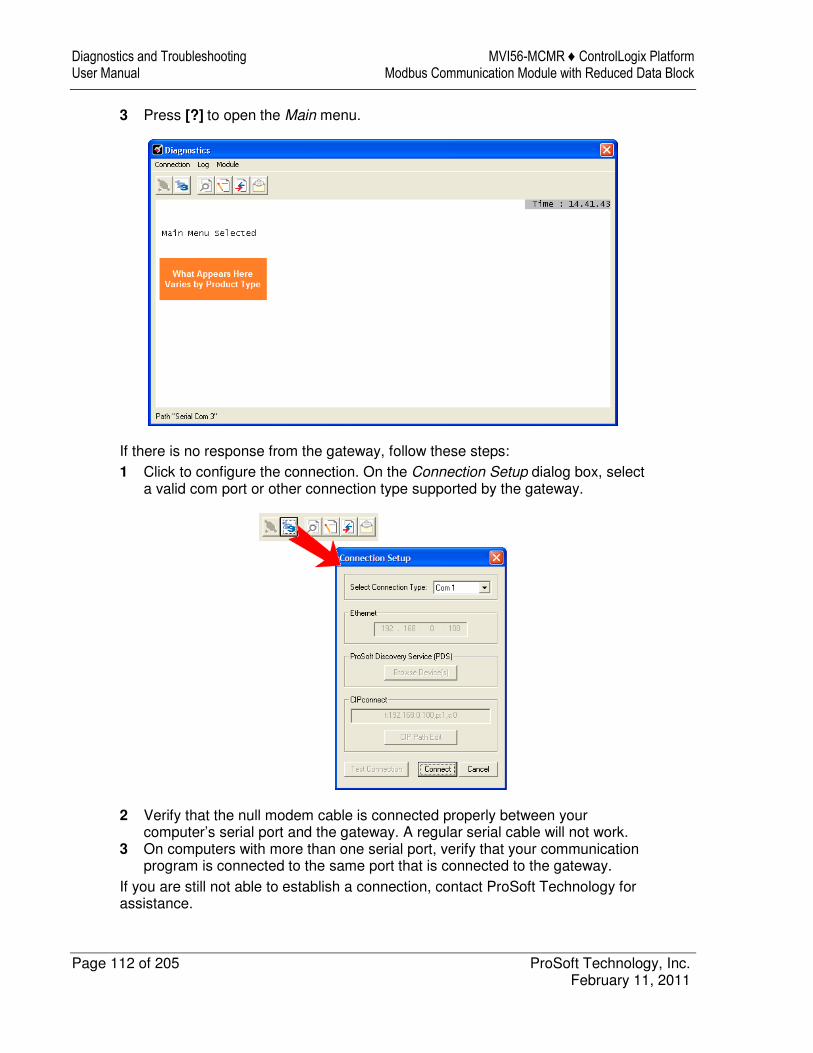
Diagnostics and Troubleshooting MVI56-MCMR ♦ ControlLogix Platform User Manual Modbus Communication Module with Reduced Data Block
Page 112 of 205 ProSoft Technology, Inc. February 11, 2011
3 Press [?] to open the Main menu.
If there is no response from the gateway, follow these steps: 1 Click to configure the connection. On the Connection Setup dialog box, select
a valid com port or other connection type supported by the gateway.
2 Verify that the null modem cable is connected properly between your computer’s serial port and the gateway. A regular serial cable will not work.
3 On computers with more than one serial port, verify that your communication program is connected to the same port that is connected to the gateway.
If you are still not able to establish a connection, contact ProSoft Technology for assistance.

MVI56-MCMR ♦ ControlLogix Platform Diagnostics and Troubleshooting Modbus Communication Module with Reduced Data Block User Manual
ProSoft Technology, Inc. Page 113 of 205 February 11, 2011
8.2.2 Navigation
All of the submenus for this gateway contain commands to redisplay the menu or return to the previous menu. You can always return from a submenu to the next higher menu by pressing [M] on your keyboard. The organization of the menu structure is represented in simplified form in the following illustration:
The remainder of this section shows the menus available for this gateway, and briefly discusses the commands available to you.
Keystrokes
The keyboard commands on these menus are usually not case sensitive. You can enter most commands in lowercase or uppercase letters. The menus use a few special characters (?, -, +, @) that must be entered exactly as shown. Some of these characters will require you to use the SHIFT, CTRL, or ALT keys to enter them correctly. For example, on US English keyboards, enter the ? command as SHIFT and /. Also, take care to distinguish the different uses for uppercase letter "eye" (I), lowercase letter "el" (L), and the number one (1). Likewise, uppercase letter "oh" (O) and the number zero (0) are not interchangeable. Although these characters look alike on the screen, they perform different actions on the gateway and may not be used interchangeably.
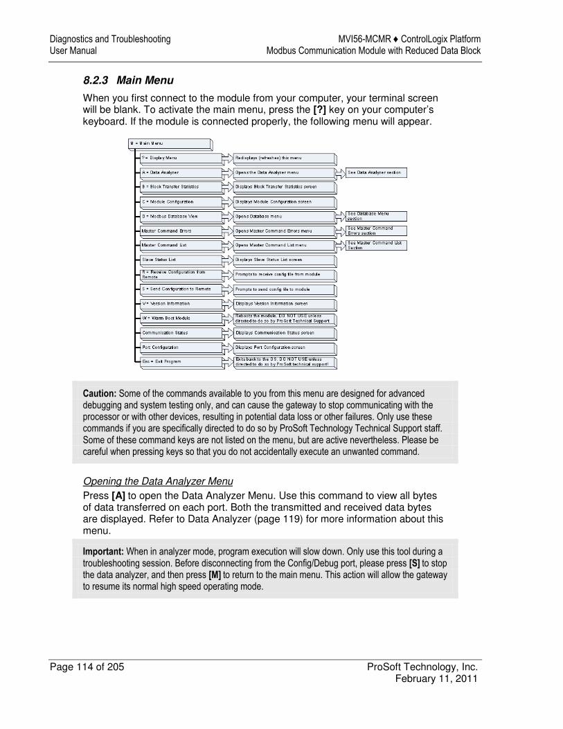
Diagnostics and Troubleshooting MVI56-MCMR ♦ ControlLogix Platform User Manual Modbus Communication Module with Reduced Data Block
Page 114 of 205 ProSoft Technology, Inc. February 11, 2011
8.2.3 Main Menu
When you first connect to the module from your computer, your terminal screen will be blank. To activate the main menu, press the [?] key on your computer’s keyboard. If the module is connected properly, the following menu will appear.
Caution: Some of the commands available to you from this menu are designed for advanced debugging and system testing only, and can cause the gateway to stop communicating with the processor or with other devices, resulting in potential data loss or other failures. Only use these commands if you are specifically directed to do so by ProSoft Technology Technical Support staff. Some of these command keys are not listed on the menu, but are active nevertheless. Please be careful when pressing keys so that you do not accidentally execute an unwanted command.
Opening the Data Analyzer Menu
Press [A] to open the Data Analyzer Menu. Use this command to view all bytes of data transferred on each port. Both the transmitted and received data bytes are displayed. Refer to Data Analyzer (page 119) for more information about this menu.
Important: When in analyzer mode, program execution will slow down. Only use this tool during a troubleshooting session. Before disconnecting from the Config/Debug port, please press [S] to stop the data analyzer, and then press [M] to return to the main menu. This action will allow the gateway to resume its normal high speed operating mode.
MVI56-MCMR ♦ ControlLogix Platform Diagnostics and Troubleshooting Modbus Communication Module with Reduced Data Block User Manual
ProSoft Technology, Inc. Page 115 of 205 February 11, 2011
Viewing Block Transfer Statistics
Press [B] from the Main menu to view the Block Transfer Statistics screen. Use this command to display the configuration and statistics of the backplane data transfer operations between the module and the processor. The information on this screen can help determine if there are communication problems between the processor and the module.
Tip: To determine the number of blocks transferred each second, mark the numbers displayed at a specific time. Then some seconds later activate the command again. Subtract the previous numbers from the current numbers and divide by the quantity of seconds passed between the two readings.
Viewing Module Configuration
Press [C] to view the Module Configuration screen. Use this command to display the current configuration and statistics for the gateway.
Opening the Database View Menu
Press [D] to open the Database View menu. Use this menu command to view the current contents of the gateway’s database. For more information about this submenu, see Database View Menu (page 124).
Opening the Command Error List Menu
Press [E] (port 1) or [F] (port 2) to open the Command Error List. This list consists of multiple pages of command list error/status data. Press [?] to view a list of commands available on this menu.
Opening the Master Command List Menu (Ports 1 and 2)
Press [I] (port 1) or [J] (port 2) to open the master command list menu for the specified port. Press [?] to view the menu.
Viewing the Slave Status List (Port 1 and 2)
Press [O] (port 1) or [P] (port 2) to view the 256 slave status values associated with the ports. The slave status values are defined as follows: 0 = slave is not used 1 = slave being actively polled 2 = slave suspended
Diagnostics and Troubleshooting MVI56-MCMR ♦ ControlLogix Platform User Manual Modbus Communication Module with Reduced Data Block
Page 116 of 205 ProSoft Technology, Inc. February 11, 2011
Viewing Version Information
Press [V] to view version information for the gateway. Use this command to view the current version of the software for the gateway, as well as other important values. You may be asked to provide this information when calling for technical support on the product. Values at the bottom of the display are important in determining gateway operation. The Program Scan Counter value is incremented each time a gateway’s program cycle is complete.
Tip: Repeat this command at one-second intervals to determine the frequency of program execution.
Warm Booting the Module
Press [W] from the Main menu to warm boot (restart) the gateway. This command will cause the program to exit and reload, refreshing configuration parameters that must be set on program initialization. Only use this command if you must force the gateway to reboot.
Transferring the Configuration File from the PC to the Module
On the Diagnostics Menu this is referred to as Receive Module Configuration. Press [R] to receive (download) the configuration file from your PC to the module and store the file on the module’s Compact Flash Card (Personality Module) or Flash RAM. Press [Y] to confirm the file transfer, and then follow the instructions on the terminal screen to complete the file transfer process. After the file has been successfully downloaded, the module will restart the program and load the new configuration information. Review the new configuration using menu commands [6] and [0] to verify that the module is configured correctly.
Transferring the Configuration File from The Module to the PC
On the Diagnostics Menu this is referred to as Send Module Configuration. Press [S] to send (upload) the configuration file from the gateway to your PC. Press [Y] to confirm the file transfer, and then follow the instructions on the terminal screen to complete the file transfer process. After the file has been successfully uploaded, you can open and edit the file to change the gateway’s configuration.
MVI56-MCMR ♦ ControlLogix Platform Diagnostics and Troubleshooting Modbus Communication Module with Reduced Data Block User Manual
ProSoft Technology, Inc. Page 117 of 205 February 11, 2011
Viewing Port Communication Status
Press [1] or [2] from the Main Menu to view the port communication status for Ports 1 and 2. Use this command to view communication status and statistics for the selected port. This information can be informative when troubleshooting communication problems.
Viewing Port Configuration
Press [6] or [7] from the Main Menu to view configuration information for ports 1 and 2. Use this command to display detailed configuration information for the selected port.
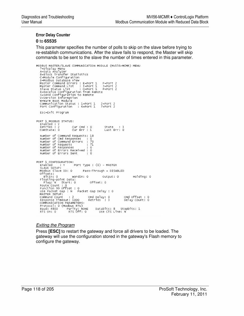
Diagnostics and Troubleshooting MVI56-MCMR ♦ ControlLogix Platform User Manual Modbus Communication Module with Reduced Data Block
Page 118 of 205 ProSoft Technology, Inc. February 11, 2011
Error Delay Counter
0 to 65535 This parameter specifies the number of polls to skip on the slave before trying to re-establish communications. After the slave fails to respond, the Master will skip commands to be sent to the slave the number of times entered in this parameter.
Exiting the Program
Press [ESC] to restart the gateway and force all drivers to be loaded. The gateway will use the configuration stored in the gateway's Flash memory to configure the gateway.
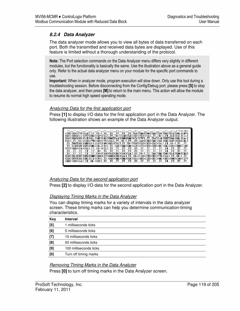
MVI56-MCMR ♦ ControlLogix Platform Diagnostics and Troubleshooting Modbus Communication Module with Reduced Data Block User Manual
ProSoft Technology, Inc. Page 119 of 205 February 11, 2011
8.2.4 Data Analyzer
The data analyzer mode allows you to view all bytes of data transferred on each port. Both the transmitted and received data bytes are displayed. Use of this feature is limited without a thorough understanding of the protocol.
Note: The Port selection commands on the Data Analyzer menu differs very slightly in different modules, but the functionality is basically the same. Use the illustration above as a general guide only. Refer to the actual data analyzer menu on your module for the specific port commands to use. Important: When in analyzer mode, program execution will slow down. Only use this tool during a troubleshooting session. Before disconnecting from the Config/Debug port, please press [S] to stop the data analyzer, and then press [M] to return to the main menu. This action will allow the module to resume its normal high speed operating mode.
Analyzing Data for the first application port
Press [1] to display I/O data for the first application port in the Data Analyzer. The following illustration shows an example of the Data Analyzer output.
Analyzing Data for the second application port
Press [2] to display I/O data for the second application port in the Data Analyzer.
Displaying Timing Marks in the Data Analyzer
You can display timing marks for a variety of intervals in the data analyzer screen. These timing marks can help you determine communication-timing characteristics.
Key Interval
[5] 1 milliseconds ticks
[6] 5 milliseconds ticks
[7] 10 milliseconds ticks
[8] 50 milliseconds ticks
[9] 100 milliseconds ticks
[0] Turn off timing marks
Removing Timing Marks in the Data Analyzer
Press [0] to turn off timing marks in the Data Analyzer screen.
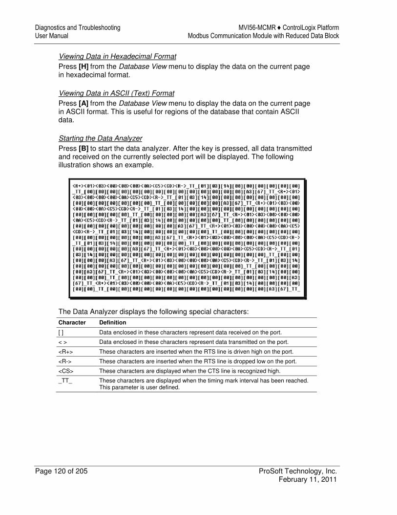
Diagnostics and Troubleshooting MVI56-MCMR ♦ ControlLogix Platform User Manual Modbus Communication Module with Reduced Data Block
Page 120 of 205 ProSoft Technology, Inc. February 11, 2011
Viewing Data in Hexadecimal Format
Press [H] from the Database View menu to display the data on the current page in hexadecimal format.
Viewing Data in ASCII (Text) Format
Press [A] from the Database View menu to display the data on the current page in ASCII format. This is useful for regions of the database that contain ASCII data.
Starting the Data Analyzer
Press [B] to start the data analyzer. After the key is pressed, all data transmitted and received on the currently selected port will be displayed. The following illustration shows an example.
The Data Analyzer displays the following special characters:
Character Definition
[ ] Data enclosed in these characters represent data received on the port.
< > Data enclosed in these characters represent data transmitted on the port.
<R+> These characters are inserted when the RTS line is driven high on the port.
<R-> These characters are inserted when the RTS line is dropped low on the port.
<CS> These characters are displayed when the CTS line is recognized high.
_TT_ These characters are displayed when the timing mark interval has been reached. This parameter is user defined.
MVI56-MCMR ♦ ControlLogix Platform Diagnostics and Troubleshooting Modbus Communication Module with Reduced Data Block User Manual
ProSoft Technology, Inc. Page 121 of 205 February 11, 2011
Stopping the Data Analyzer
Press [S] to stop the data analyzer. Use this option to freeze the display so the data can be analyzed. To restart the analyzer, press [B].
Important: When in analyzer mode, program execution will slow down. Only use this tool during a troubleshooting session. Before disconnecting from the Config/Debug port, please press [S] to stop the data analyzer, and then press [M] to return to the main menu. This action will allow the module to resume its normal high speed operating mode.
Returning to the Main Menu
Press [M] to return to the Main menu.
Data Analyzer Tips
From the main menu, press [A] for the "Data Analyzer". You should see the following text appear on the screen:
After the "Data Analyzer" mode has been selected, press [?] to view the Data Analyzer menu. From this menu, you can select the "Port", the "format", and the "ticks" that you can display the data in. For most applications, HEX is the best format to view the data, and this does include ASCII based messages (because some characters will not display on HyperTerminal and by capturing the data in HEX, we can figure out what the corresponding ASCII characters are supposed to be). The Tick value is a timing mark. The module will print a _TT for every xx milliseconds of no data on the line. Usually 10milliseconds is the best value to start with.
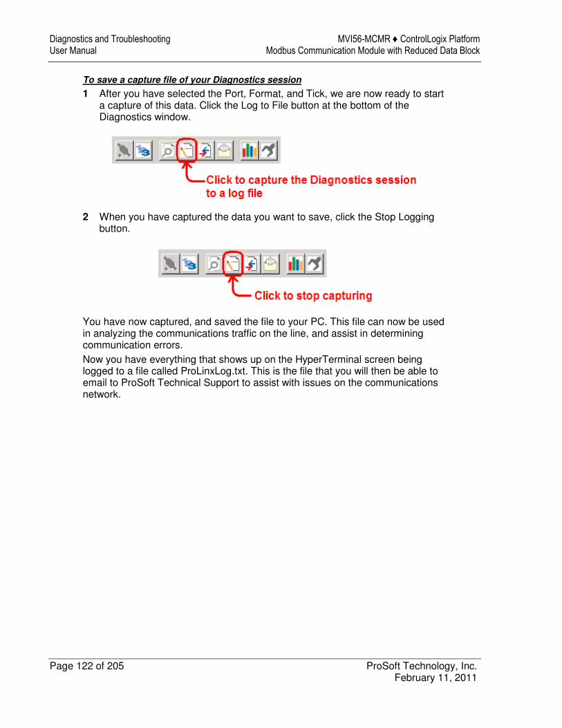
Diagnostics and Troubleshooting MVI56-MCMR ♦ ControlLogix Platform User Manual Modbus Communication Module with Reduced Data Block
Page 122 of 205 ProSoft Technology, Inc. February 11, 2011
To save a capture file of your Diagnostics session
1 After you have selected the Port, Format, and Tick, we are now ready to start a capture of this data. Click the Log to File button at the bottom of the Diagnostics window.
2 When you have captured the data you want to save, click the Stop Logging button.
You have now captured, and saved the file to your PC. This file can now be used in analyzing the communications traffic on the line, and assist in determining communication errors. Now you have everything that shows up on the HyperTerminal screen being logged to a file called ProLinxLog.txt. This is the file that you will then be able to email to ProSoft Technical Support to assist with issues on the communications network.
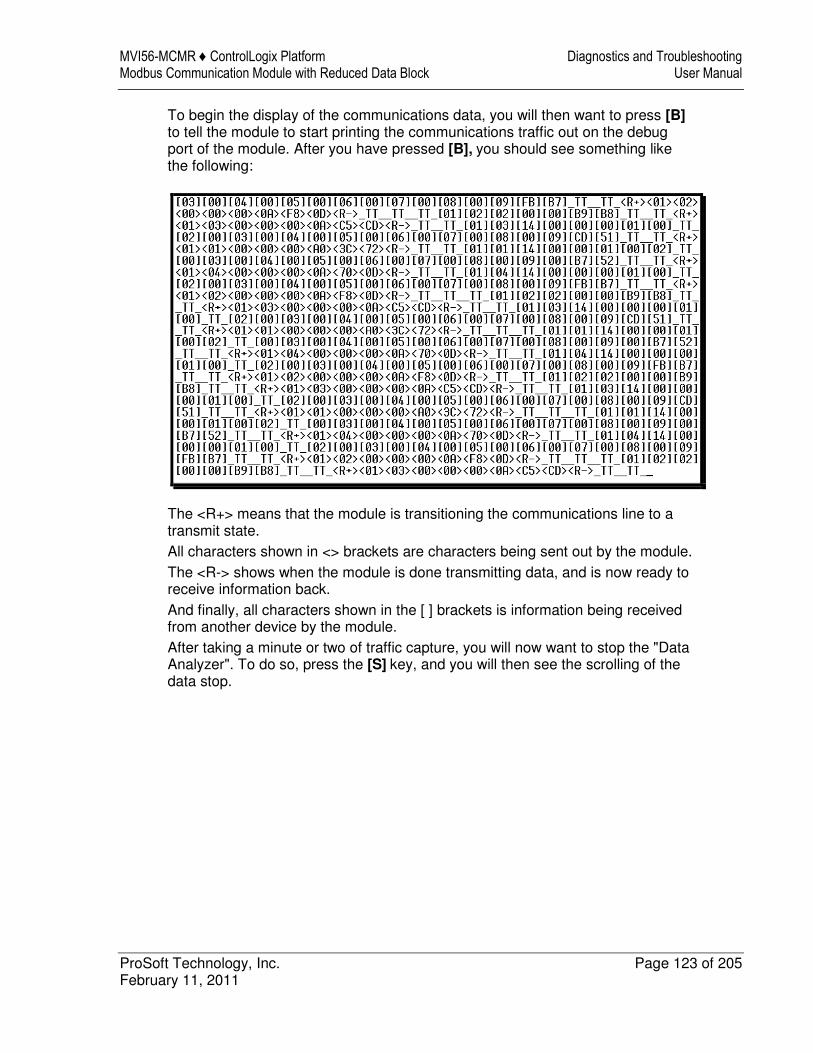
MVI56-MCMR ♦ ControlLogix Platform Diagnostics and Troubleshooting Modbus Communication Module with Reduced Data Block User Manual
ProSoft Technology, Inc. Page 123 of 205 February 11, 2011
To begin the display of the communications data, you will then want to press [B] to tell the module to start printing the communications traffic out on the debug port of the module. After you have pressed [B], you should see something like the following:
The <R+> means that the module is transitioning the communications line to a transmit state. All characters shown in <> brackets are characters being sent out by the module. The <R-> shows when the module is done transmitting data, and is now ready to receive information back. And finally, all characters shown in the [ ] brackets is information being received from another device by the module. After taking a minute or two of traffic capture, you will now want to stop the "Data Analyzer". To do so, press the [S] key, and you will then see the scrolling of the data stop.
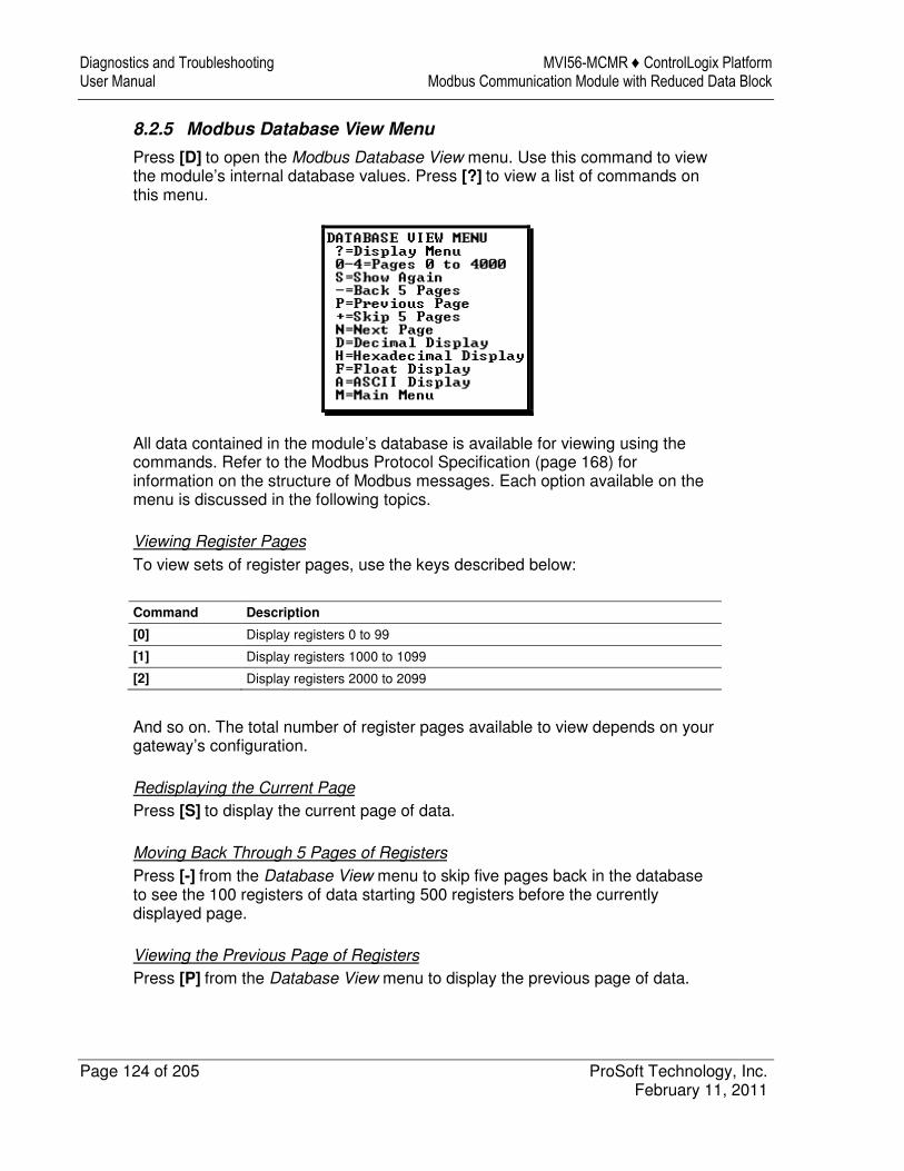
Diagnostics and Troubleshooting MVI56-MCMR ♦ ControlLogix Platform User Manual Modbus Communication Module with Reduced Data Block
Page 124 of 205 ProSoft Technology, Inc. February 11, 2011
8.2.5 Modbus Database View Menu
Press [D] to open the Modbus Database View menu. Use this command to view the module’s internal database values. Press [?] to view a list of commands on this menu.
All data contained in the module’s database is available for viewing using the commands. Refer to the Modbus Protocol Specification (page 168) for information on the structure of Modbus messages. Each option available on the menu is discussed in the following topics.
Viewing Register Pages
To view sets of register pages, use the keys described below:
Command Description
[0] Display registers 0 to 99
[1] Display registers 1000 to 1099
[2] Display registers 2000 to 2099
And so on. The total number of register pages available to view depends on your gateway’s configuration.
Redisplaying the Current Page
Press [S] to display the current page of data.
Moving Back Through 5 Pages of Registers
Press [-] from the Database View menu to skip five pages back in the database to see the 100 registers of data starting 500 registers before the currently displayed page.
Viewing the Previous Page of Registers
Press [P] from the Database View menu to display the previous page of data.
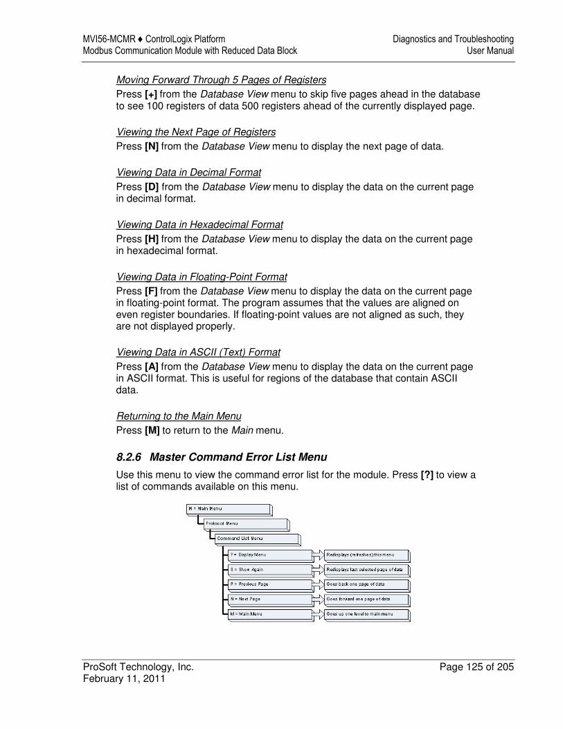
MVI56-MCMR ♦ ControlLogix Platform Diagnostics and Troubleshooting Modbus Communication Module with Reduced Data Block User Manual
ProSoft Technology, Inc. Page 125 of 205 February 11, 2011
Moving Forward Through 5 Pages of Registers
Press [+] from the Database View menu to skip five pages ahead in the database to see 100 registers of data 500 registers ahead of the currently displayed page.
Viewing the Next Page of Registers
Press [N] from the Database View menu to display the next page of data.
Viewing Data in Decimal Format
Press [D] from the Database View menu to display the data on the current page in decimal format.
Viewing Data in Hexadecimal Format
Press [H] from the Database View menu to display the data on the current page in hexadecimal format.
Viewing Data in Floating-Point Format
Press [F] from the Database View menu to display the data on the current page in floating-point format. The program assumes that the values are aligned on even register boundaries. If floating-point values are not aligned as such, they are not displayed properly.
Viewing Data in ASCII (Text) Format
Press [A] from the Database View menu to display the data on the current page in ASCII format. This is useful for regions of the database that contain ASCII data.
Returning to the Main Menu
Press [M] to return to the Main menu.
8.2.6 Master Command Error List Menu
Use this menu to view the command error list for the module. Press [?] to view a list of commands available on this menu.
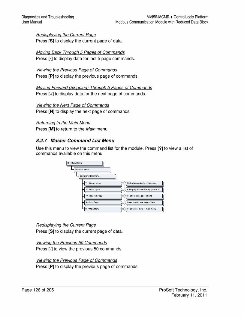
Diagnostics and Troubleshooting MVI56-MCMR ♦ ControlLogix Platform User Manual Modbus Communication Module with Reduced Data Block
Page 126 of 205 ProSoft Technology, Inc. February 11, 2011
Redisplaying the Current Page
Press [S] to display the current page of data.
Moving Back Through 5 Pages of Commands
Press [-] to display data for last 5 page commands.
Viewing the Previous Page of Commands
Press [P] to display the previous page of commands.
Moving Forward (Skipping) Through 5 Pages of Commands
Press [+] to display data for the next page of commands.
Viewing the Next Page of Commands
Press [N] to display the next page of commands.
Returning to the Main Menu
Press [M] to return to the Main menu.
8.2.7 Master Command List Menu
Use this menu to view the command list for the module. Press [?] to view a list of commands available on this menu.
Redisplaying the Current Page
Press [S] to display the current page of data.
Viewing the Previous 50 Commands
Press [-] to view the previous 50 commands.
Viewing the Previous Page of Commands
Press [P] to display the previous page of commands.
MVI56-MCMR ♦ ControlLogix Platform Diagnostics and Troubleshooting Modbus Communication Module with Reduced Data Block User Manual
ProSoft Technology, Inc. Page 127 of 205 February 11, 2011
Viewing the Next 50 Commands
Press [+] to view the next 50 commands from the master command list.
Viewing the Next Page of Commands
Press [N] to display the next page of commands.
Returning to the Main Menu
Press [M] to return to the Main menu.
Diagnostics and Troubleshooting MVI56-MCMR ♦ ControlLogix Platform User Manual Modbus Communication Module with Reduced Data Block
Page 128 of 205 ProSoft Technology, Inc. February 11, 2011
8.3 Reading Status Data from the Module
The MVI56-MCMR module returns a 33-word Status Data block that can be used to determine the module’s operating status. This data is transferred to the ControlLogix processor with an MSG instruction. For a complete listing of the status data object, refer to MVI56-MCMR Status Data Definition (page 166).

MVI56-MCMR ♦ ControlLogix Platform Diagnostics and Troubleshooting Modbus Communication Module with Reduced Data Block User Manual
ProSoft Technology, Inc. Page 129 of 205 February 11, 2011
8.4 Communication Error Codes
During module configuration download, the OK and APP LEDs will cycle through various states. If the OK LED remains RED and the APP LED remains OFF or RED for a long period of time, look at the configuration error words in the configuration request block. The structure of the block is shown in the following table.
Offset Description Length
0 Reserved 1
1 9000 1
2 Module Configuration Errors 1
3 Port 1 Configuration Errors 1
4 Port 2 Configuration Errors 1
5 to 248 Spare 244
249 -2 or -3 1
The bits in each configuration word are shown in the following table. The module configuration error word has the following definition:
Bit Description Value
0 Read block start value is greater than the database size. 0x0001
1 Read block start value is less than zero. 0x0002
2 Read block count value is less than zero. 0x0004
3 Read block count + start is greater than the database size. 0x0008
4 Write block start value is greater than the database size. 0x0010
5 Write block start value is less than zero. 0x0020
6 Write block count value is less than zero. 0x0040
7 Write block count + start is greater than the database size. 0x0080
8 0x0100
9 0x0200
10 0x0400
11 0x0800
12 0x1000
13 0x2000
14 0x4000
15 0x8000
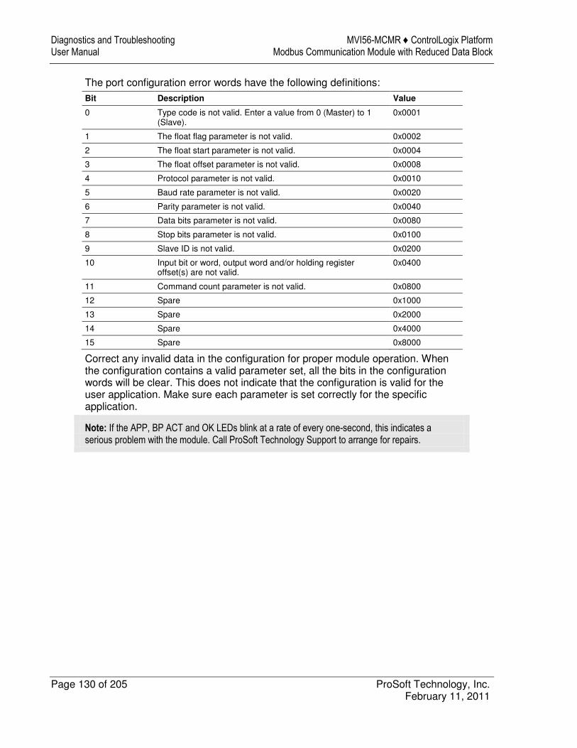
Diagnostics and Troubleshooting MVI56-MCMR ♦ ControlLogix Platform User Manual Modbus Communication Module with Reduced Data Block
Page 130 of 205 ProSoft Technology, Inc. February 11, 2011
The port configuration error words have the following definitions: Bit Description Value
0 Type code is not valid. Enter a value from 0 (Master) to 1 (Slave).
0x0001
1 The float flag parameter is not valid. 0x0002
2 The float start parameter is not valid. 0x0004
3 The float offset parameter is not valid. 0x0008
4 Protocol parameter is not valid. 0x0010
5 Baud rate parameter is not valid. 0x0020
6 Parity parameter is not valid. 0x0040
7 Data bits parameter is not valid. 0x0080
8 Stop bits parameter is not valid. 0x0100
9 Slave ID is not valid. 0x0200
10 Input bit or word, output word and/or holding register offset(s) are not valid.
0x0400
11 Command count parameter is not valid. 0x0800
12 Spare 0x1000
13 Spare 0x2000
14 Spare 0x4000
15 Spare 0x8000
Correct any invalid data in the configuration for proper module operation. When the configuration contains a valid parameter set, all the bits in the configuration words will be clear. This does not indicate that the configuration is valid for the user application. Make sure each parameter is set correctly for the specific application.
Note: If the APP, BP ACT and OK LEDs blink at a rate of every one-second, this indicates a serious problem with the module. Call ProSoft Technology Support to arrange for repairs.
MVI56-MCMR ♦ ControlLogix Platform Diagnostics and Troubleshooting Modbus Communication Module with Reduced Data Block User Manual
ProSoft Technology, Inc. Page 131 of 205 February 11, 2011
8.4.1 Clearing a Fault Condition
Typically, if the OK LED on the front of the module turns RED for more than ten seconds, a hardware problem has been detected in the module or the program has exited. To clear the condition, follow these steps: 1 Turn off power to the rack. 2 Remove the card from the rack. 3 Verify that all jumpers are set correctly. 4 If the module requires a Compact Flash card, verify that the card is installed
correctly. 5 Re-insert the card in the rack and turn the power back on. 6 Verify correct configuration data is being transferred to the module from the
ControlLogix controller. If the module's OK LED does not turn GREEN, verify that the module is inserted completely into the rack. If this does not cure the problem, contact ProSoft Technology Technical Support.
Diagnostics and Troubleshooting MVI56-MCMR ♦ ControlLogix Platform User Manual Modbus Communication Module with Reduced Data Block
Page 132 of 205 ProSoft Technology, Inc. February 11, 2011
8.4.2 Troubleshooting
Use the following troubleshooting steps if you encounter problems when the module is powered up. If these steps do not resolve your problem, please contact ProSoft Technology Technical Support.
Processor Errors
Problem description Steps to take
Processor fault Verify that the module is plugged into the slot that has been configured for the module in the I/O Configuration of RSLogix. Verify that the slot location in the rack has been configured correctly in the ladder logic.
Processor I/O LED flashes
This indicates a problem with backplane communications. A problem could exist between the processor and any installed I/O module, not just the MVI56-MCMR. Verify that all modules in the rack are correctly configured in the ladder logic.
Module Errors
Problem description Steps to take
BP ACT LED (not present on MVI56E modules) remains OFF or blinks slowly MVI56E modules with scrolling LED display: <Backplane Status> condition reads ERR
This indicates that backplane transfer operations are failing. Connect to the module’s Configuration/Debug port to check this. To establish backplane communications, verify the following items: � The processor is in RUN or REM RUN mode. � The backplane driver is loaded in the module. � The module is configured for read and write data block transfer. � The ladder logic handles all read and write block situations. � The module is properly configured in the processor I/O configuration
and ladder logic.
OK LED remains RED The program has halted or a critical error has occurred. Connect to the Configuration/Debug port to see if the module is running. If the program has halted, turn off power to the rack, remove the card from the rack and re-insert it, and then restore power to the rack.
MVI56-MCMR ♦ ControlLogix Platform Reference Modbus Communication Module with Reduced Data Block User Manual
ProSoft Technology, Inc. Page 133 of 205 February 11, 2011
9 Reference
In This Chapter
� About the MODBUS Protocol .............................................................. 134
� Specifications ...................................................................................... 135
� Functional Overview ............................................................................ 139
� Cable Connections .............................................................................. 161
� MVI56-MCMR Status Data Definition .................................................. 166
� Modbus Protocol Specification ............................................................ 168
� Using the Sample Program - RSLogix 5000 Version 15 and earlier .... 181
Reference MVI56-MCMR ♦ ControlLogix Platform User Manual Modbus Communication Module with Reduced Data Block
Page 134 of 205 ProSoft Technology, Inc. February 11, 2011
9.1 About the MODBUS Protocol
MODBUS is a widely-used protocol originally developed by Modicon in 1978. Since that time, the protocol has been adopted as a standard throughout the automation industry. The original MODBUS specification uses a serial connection to communicate commands and data between Master and Slave devices on a network. Later enhancements to the protocol allow communication over other types of networks. MODBUS is a Master/Slave protocol. The Master establishes a connection to the remote Slave. When the connection is established, the Master sends the MODBUS commands to the Slave. The MVI56-MCMR module can work as a Master and as a Slave. The MVI56-MCMR module also works as an input/output module between itself and the Rockwell Automation backplane and processor. The module uses an internal database to pass data and commands between the processor and Master and Slave devices on MODBUS networks.
MVI56-MCMR ♦ ControlLogix Platform Reference Modbus Communication Module with Reduced Data Block User Manual
ProSoft Technology, Inc. Page 135 of 205 February 11, 2011
9.2 Specifications
The MVI56 Modbus Master/Slave Communication Module with Reduced Data Block allows users to integrate Modbus devices and networks into the Rockwell Automation® ControlLogix® architecture. Compatible devices include not only Modicon® PLCs (almost all support the Modbus protocol) but also a wide assortment of processors, HMI displays, SCADA systems and field devices made by a variety of manufacturers. The module acts as an input/output module between the Modbus network and the ControlLogix processor. The data transfers between the module and the processor are asynchronous from communications on the Modbus network. A 5000-word register space in the module hold the data to exchanged between the processor and the Modbus network.
9.2.1 General Specifications
� Single Slot - ControlLogix backplane compatible � Designed especially for remote rack implementations � The module is recognized as an Input/Output module and has access to
processor memory for data transfer � Ladder Logic is used for data transfer between module and processor.
Sample Ladder File included � Configuration data obtained from configuration file downloaded to module.
Sample configuration file included
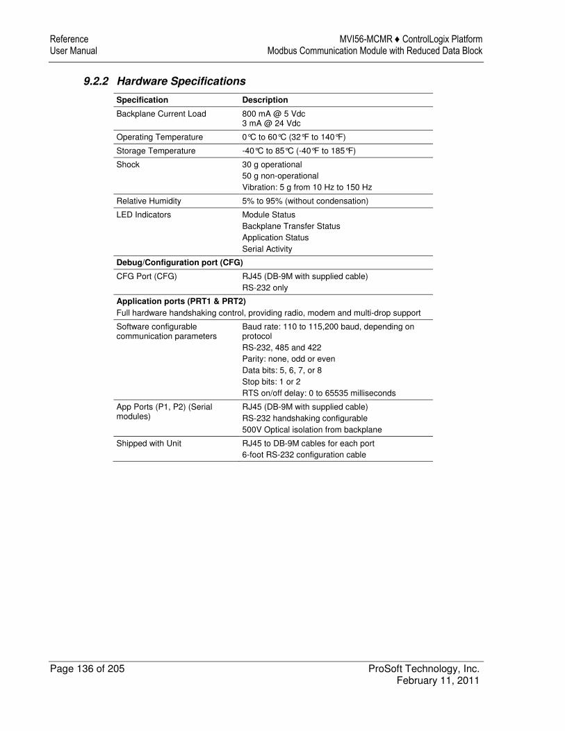
Reference MVI56-MCMR ♦ ControlLogix Platform User Manual Modbus Communication Module with Reduced Data Block
Page 136 of 205 ProSoft Technology, Inc. February 11, 2011
9.2.2 Hardware Specifications
Specification Description
Backplane Current Load 800 mA @ 5 Vdc 3 mA @ 24 Vdc
Operating Temperature 0°C to 60°C (32°F to 140°F)
Storage Temperature -40°C to 85°C (-40°F to 185°F)
Shock 30 g operational 50 g non-operational Vibration: 5 g from 10 Hz to 150 Hz
Relative Humidity 5% to 95% (without condensation)
LED Indicators Module Status Backplane Transfer Status Application Status Serial Activity
Debug/Configuration port (CFG)
CFG Port (CFG) RJ45 (DB-9M with supplied cable) RS-232 only
Application ports (PRT1 & PRT2)
Full hardware handshaking control, providing radio, modem and multi-drop support
Software configurable communication parameters
Baud rate: 110 to 115,200 baud, depending on protocol RS-232, 485 and 422 Parity: none, odd or even Data bits: 5, 6, 7, or 8 Stop bits: 1 or 2 RTS on/off delay: 0 to 65535 milliseconds
App Ports (P1, P2) (Serial modules)
RJ45 (DB-9M with supplied cable) RS-232 handshaking configurable 500V Optical isolation from backplane
Shipped with Unit RJ45 to DB-9M cables for each port 6-foot RS-232 configuration cable
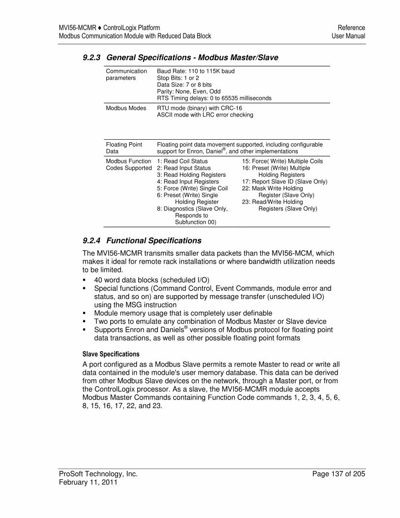
MVI56-MCMR ♦ ControlLogix Platform Reference Modbus Communication Module with Reduced Data Block User Manual
ProSoft Technology, Inc. Page 137 of 205 February 11, 2011
9.2.3 General Specifications - Modbus Master/Slave
Communication parameters
Baud Rate: 110 to 115K baud Stop Bits: 1 or 2 Data Size: 7 or 8 bits Parity: None, Even, Odd RTS Timing delays: 0 to 65535 milliseconds
Modbus Modes RTU mode (binary) with CRC-16 ASCII mode with LRC error checking
Floating Point Data
Floating point data movement supported, including configurable support for Enron, Daniel®, and other implementations
Modbus Function Codes Supported
1: Read Coil Status 2: Read Input Status 3: Read Holding Registers 4: Read Input Registers 5: Force (Write) Single Coil 6: Preset (Write) Single Holding Register 8: Diagnostics (Slave Only, Responds to Subfunction 00)
15: Force( Write) Multiple Coils 16: Preset (Write) Multiple Holding Registers 17: Report Slave ID (Slave Only) 22: Mask Write Holding Register (Slave Only) 23: Read/Write Holding Registers (Slave Only)
9.2.4 Functional Specifications
The MVI56-MCMR transmits smaller data packets than the MVI56-MCM, which makes it ideal for remote rack installations or where bandwidth utilization needs to be limited. � 40 word data blocks (scheduled I/O) � Special functions (Command Control, Event Commands, module error and
status, and so on) are supported by message transfer (unscheduled I/O) using the MSG instruction
� Module memory usage that is completely user definable � Two ports to emulate any combination of Modbus Master or Slave device � Supports Enron and Daniels® versions of Modbus protocol for floating point
data transactions, as well as other possible floating point formats
Slave Specifications
A port configured as a Modbus Slave permits a remote Master to read or write all data contained in the module's user memory database. This data can be derived from other Modbus Slave devices on the network, through a Master port, or from the ControlLogix processor. As a slave, the MVI56-MCMR module accepts Modbus Master Commands containing Function Code commands 1, 2, 3, 4, 5, 6, 8, 15, 16, 17, 22, and 23.
Reference MVI56-MCMR ♦ ControlLogix Platform User Manual Modbus Communication Module with Reduced Data Block
Page 138 of 205 ProSoft Technology, Inc. February 11, 2011
Master Specifications
A port configured as a Modbus Master actively issues Modbus commands to Modbus Slave Device Addresses on the Modbus network. As a Modbus Master, the module can issue commands using Function Codes 1, 2, 3, 4, 5, 6, 15, and 16. One hundred (100) pre-configured commands can be created for each port. Normal Modus polling is handled automatically by the module based on the user's command configuration. The ControlLogix processor can also be programmed to control Master polling activity on the port under special conditions by actively selecting commands from the command list to execute (Command Control) or issuing commands directly from the ladder logic (Event Commands). Additionally, the Master ports can optimize network throughput by setting poll frequency of each command individually and by polling Slaves with communication problems less frequently.
MVI56-MCMR ♦ ControlLogix Platform Reference Modbus Communication Module with Reduced Data Block User Manual
ProSoft Technology, Inc. Page 139 of 205 February 11, 2011
9.3 Functional Overview
9.3.1 Processor/Module Data Transfers
The MVI56-MCMR module communicates directly over the ControlLogix backplane or across any supported 1756 network bridge (the most common being 1756-CNBx Control Net Bridge and 1756-ENxT EtherNet/IP Bridge). Data travels between the module and the ControlLogix processor across the backplane or network using the module's Input and Output Images and MSG instructions. The data update frequency is determined by the Requested Packet Interval (RPI) defined in the module's I/O configuration and the communication load and speed on the Modbus, ControlNet, or EtherNet/IP networks. When the module is installed in the ControlLogix chassis, typical backplane update rates range from 1 to 10 milliseconds. Execution time for MSG instruction data transfers are dependant on the amount of unscheduled time available on the backplane or network and how frequently the MSG instruction is executed. Data received by the Modbus driver is placed in the module's internal memory in an area designated to receive it. The data in this area is then transferred to the processor in the I/O Input Image. This data is processed by ladder logic to fill the MCMR.DATA.READDATA array controller tags. The Input Image size is 42 words per image block, 40 of which are user data, along with two control words. Larger amounts of user data can be moved from the module to the processor by using multiple sequential block transfers. The module will automatically sequence multiple 40-word blocks until the total amount of user data has been moved. The module calculates the required number of read data blocks by dividing the READ
REGISTER COUNT parameter in the configuration file by 40 and rounding up to the next higher whole integer value. The processor inserts data in the module's Output Image to transfer to the module. The module's program extracts the data and stores it in the internal module database, so that it may be transmitted by the Master driver to Slaves on serial network. Additionally, the ControlLogix processor can send special function blocks to the module to instruct it to perform special tasks. The Output Image size is 42 words per image block, 40 of which are user data, along with one control word. Larger amounts of user data can be moved from the processor to the module by using multiple sequential block transfers. The module will automatically sequence multiple 40-word blocks until the total amount of user data has been moved. The module calculates the required number of write data blocks by dividing the Write Register Count parameter in the configuration file by 40 and rounding up to the next higher whole integer value. Special function blocks are also passed between the module and the processor using MSG instructions initiated under ladder logic control. These blocks are transferred between the processor and the module only when triggered by user-programmed logic.
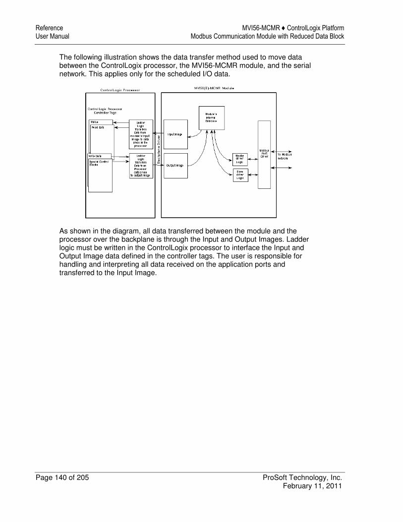
Reference MVI56-MCMR ♦ ControlLogix Platform User Manual Modbus Communication Module with Reduced Data Block
Page 140 of 205 ProSoft Technology, Inc. February 11, 2011
The following illustration shows the data transfer method used to move data between the ControlLogix processor, the MVI56-MCMR module, and the serial network. This applies only for the scheduled I/O data.
As shown in the diagram, all data transferred between the module and the processor over the backplane is through the Input and Output Images. Ladder logic must be written in the ControlLogix processor to interface the Input and Output Image data defined in the controller tags. The user is responsible for handling and interpreting all data received on the application ports and transferred to the Input Image.
MVI56-MCMR ♦ ControlLogix Platform Reference Modbus Communication Module with Reduced Data Block User Manual
ProSoft Technology, Inc. Page 141 of 205 February 11, 2011
Using Data Blocks
Each block transferred between the module and the processor contains block identification codes that define the content or function of the block of data transferred. Blocks -1 and 0 contain no data when transferred from the processor to the module. Blocks 1 to 125 transfer data stored or to be stored in the module’s database 40-words of data per block. These data blocks send data from module to the processor (monitored data received from the devices on the serial network) and to send data from the processor to the module (control data to send to the end devices). Block identification codes 9901 to 9999 are used for special function blocks to control the module. The following table describes the block identification codes used by the module.
Available When Port:
Type Block # Range
Block Descriptions Is Master? Is Slave?
I/O -1 and 0 Null (Used when Read or Write Register Count = 0)
Yes Yes
I/O 1 to 125 Read or Write Data Blocks Yes Yes
I/O 1000 to 1125 Initialize Output Data Blocks Yes Yes
MSG 9250 Module Error/Status Data Block Yes Yes
MSG 9901 Event Command Block for Port 1 Yes No
MSG 9911 Event Command Block for Port 2 Yes No
MSG 9902 Command Control Block for Port 1 Yes No
MSG 9912 Command Control Block for Port 2 Yes No
MSG 9950 Get Command Error List for Port 1 Block Yes No
MSG 9951 Get Command Error List for Port 2 Block Yes No
MSG 9960 Get Slave Enable/Disable Data for Port 1 Block
Yes No
MSG 9961 Get Slave Enable/Disable Data for Port 2 Block
Yes No
I/O 9998 Warm Boot Request Block Yes Yes
I/O 9999 Cold Boot Request Block Yes Yes
As you can see, some data is transferred between the module and the ControlLogix processor using the Input and Output Images (Type=I/O), and some is transferred using MSG blocks (Type=MSG). Data transferred using the Input and Output Images is used for high-speed, deterministic delivery time data, controlled by the Requested Packet Interval (RPI) assigned to the module in the I/O configuration in RSLogix 5000. The MSG data is used for lower priority data and is transferred using MSG instructions under ladder logic control. MSG data is handled when there is time available in the unscheduled bandwidth of the network.
Reference MVI56-MCMR ♦ ControlLogix Platform User Manual Modbus Communication Module with Reduced Data Block
Page 142 of 205 ProSoft Technology, Inc. February 11, 2011
9.3.2 Normal Data Transfer Blocks
Normal data transfer includes the transferring of data received by, or to be transmitted to, the Modbus drivers and the status data. This data is transferred through read (Input Image) and write (Output Image) blocks. Refer to Module Data (page 104) for a description of the data objects used with the blocks and the ladder logic required. The following topics discuss the structure and function of each block.
Write Block
Write Blocks transfer data from the ControlLogix processor's MCMR.DATA.WRITEDATA controller tag array to the module. The following table describes the structure of the Output Image used to transfer this data.
Write Block from Processor to Module
Word Offset Description Length
0 Write Block ID (1 to 125) 1
1 to 40 Write Data 40
41 Spare 1
The Write Block Identification Code specifies the index to the 40 words that are currently being transferred from the MCMR.DATA.WRITEDATA array to the module. If the code is set to -1 or 0, the Write Block contains no valid data, as would be the case if the configuration parameter, WRITE REGISTER COUNT, was set to 0, indicating the user did not have any data to move from the processor to the module. If the word contains a value from 1 to 125, the data contained in the block will be placed in the appropriate position of the module’s database. Data from MCMR.DATA.WriteData[0] through [39] will be transferred using Write Block ID1 and will be placed in the module's user database area beginning at the address specified in the configuration file parameter, WRITE START REGISTER. Write Block ID2 will contain data from MCMR.DATA.WriteData[40} through [79] and will be placed in the next consecutive 40-word block of the module's user database. Data will continue being transferred in 40-word blocks for the total amount of data words specified in the parameter, WRITE REGISTER COUNT. Under normal data transfer conditions, the value used for the Write Block Identification Code should be the same as that received in Read Block (Input Image) Word 0, unless some special function block is required. The special function blocks will be discussed in the next section.
MVI56-MCMR ♦ ControlLogix Platform Reference Modbus Communication Module with Reduced Data Block User Manual
ProSoft Technology, Inc. Page 143 of 205 February 11, 2011
Read Block
Read Blocks transfer data from the module to the ControlLogix processor's MCMR.DATA.READDATA controller tag array. The following table describes the structure of the input image.
Read Block from Module to Processor
Word Offset Description Length
0 Write Block ID (1 to 125) 1
1 to 40 Read Data 40
41 Read Block ID (1 to 125) 1
The Read Block Identification Code (word 41) is used to signal to the ControlLogix processor that a new block is ready for processing. It also tells the processor where in the MCMR.DATA.READDATA controller tag array to place the data contained in the block. If the value of the code is set to 1, the block contains the 40 words of data from the module database starting at the address specified in the configuration file parameter, READ START REGISTER. This data will be put into the ReadData array, starting at READDATA[0] up to READDATA[39]. Read Block ID 2 would contain the next consecutive 40 words from the module database to be placed in READDATA[40] up to READDATA[79] and so on, up to the total amount of data words specified in the configuration parameter, READ
REGISTER COUNT. The block also contains the Write Block Identification Code the module expects to receive from the processor. Under normal data transfer conditions, the ladder logic should use the Write Block Identification Code to build the appropriate Output Image data block, unless a special function block is required. The special function blocks will be discussed in the next section.
9.3.3 Special Function Blocks
Write Block Identification Codes greater than 125 cause the module to perform special functions. Some of these blocks are high-priority and are moved between the processor and the module through the Input and Output Images. Others are of low-priority and are moved using Message (MSG) instructions. Each Special Function Write Block Code has a corresponding Special Function Read Block Code, which will be returned to the processor in the next Input Image, to confirm the module received and processed the Special Function Write request. The Special Function Block Codes recognized and used by the module are defined in the following topics.
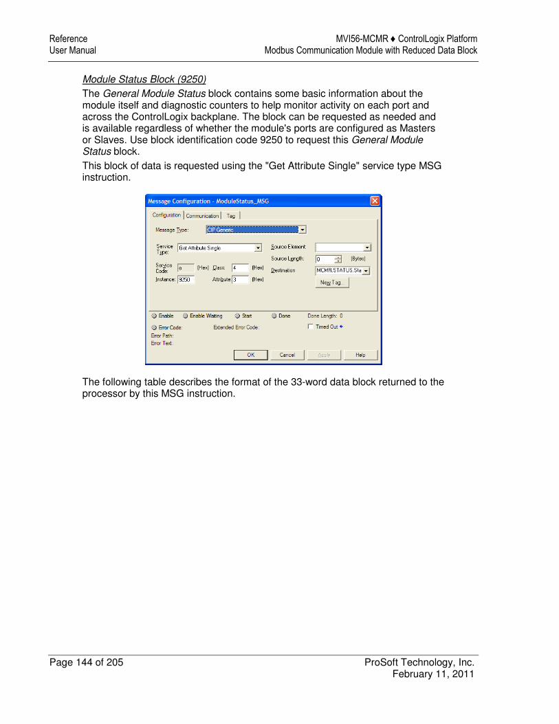
Reference MVI56-MCMR ♦ ControlLogix Platform User Manual Modbus Communication Module with Reduced Data Block
Page 144 of 205 ProSoft Technology, Inc. February 11, 2011
Module Status Block (9250)
The General Module Status block contains some basic information about the module itself and diagnostic counters to help monitor activity on each port and across the ControlLogix backplane. The block can be requested as needed and is available regardless of whether the module's ports are configured as Masters or Slaves. Use block identification code 9250 to request this General Module Status block. This block of data is requested using the "Get Attribute Single" service type MSG instruction.
The following table describes the format of the 33-word data block returned to the processor by this MSG instruction.
MVI56-MCMR ♦ ControlLogix Platform Reference Modbus Communication Module with Reduced Data Block User Manual
ProSoft Technology, Inc. Page 145 of 205 February 11, 2011
Block Response from Module to Processor
Word Offset Content Description
0 Program Scan Count This value is incremented each time a complete program cycle occurs in the module.
1 to 2 Product Code The four bytes of these two words contain the ASCII code values of the 4-letter product code.
3 to 4 Product Version These two registers contain the product version of the current running module firmware.
5 to 6 Operating System These two registers contain the month and year values for the program operating system.
7 to 8 Run Number These two registers contain the run number value for the currently running software.
9 Port 1 Command List Requests
When Port 1 is a Master, this field contains the number of requests made from Port 1 to Slave devices on the network.
10 Port 1 Command List Response
When Port 1 is a Master, this field contains the number of Slave response messages received on the port.
11 Port 1 Command List Errors When Port 1 is a Master, this field contains the number of command errors processed on the port. These errors could be due to a bad response or bad command.
12 Port 1 Requests This field contains the total number of messages sent from the port when it is a Master and the total number or messages received when it is a Slave.
13 Port 1 Responses This field contains the total number of messages sent from the port when it is a Slave and the total number or messages received when it is a Master.
14 Port 1 Errors Sent When Port 1 is a Slave, this field contains the total number of message errors sent out of the port. The Slave will send error messages when a command received is invalid.
15 Port 1 Errors Received When Port 1 is a Master, this field contains the total number of message errors received on the port from Slaves on the network. Slaves send error responses when they think they have received an invalid command or a command with invalid parameters.
16 Port 2 Command List Requests
When Port 2 is a Master, this field contains the number of requests made from Port 2 to Slave devices on the network.
17 Port 2 Command List Response
When Port 2 is a Master, this field contains the number of Slave response messages received on the port.
18 Port 2 Command List Errors When Port 2 is a Master, this field contains the number of command errors processed on the port. These errors could be due to a bad response or bad command.
19 Port 2 Requests This field contains the total number of messages sent from the port when it is a Master and the total number or messages received when it is a Slave.
20 Port 2 Responses This field contains the total number of messages sent from the port when it is a Slave and the total number or messages received when it is a Master.
Reference MVI56-MCMR ♦ ControlLogix Platform User Manual Modbus Communication Module with Reduced Data Block
Page 146 of 205 ProSoft Technology, Inc. February 11, 2011
Word Offset Content Description
21 Port 2 Errors Sent When Port 2 is a Slave, this field contains the total number of message errors sent out of the port. The Slave will send error messages when a command received is invalid.
22 Port 2 Errors Received When Port 2 is a Master, this field contains the total number of message errors received on the port from Slaves on the network. Slaves send error responses when they think they have received an invalid command or a command with invalid parameters.
23 Read Block Count This field contains the total number of Input Image blocks transferred across the backplane from the module to the processor.
24 Write Block Count This field contains the total number of Output Image blocks transferred across the backplane from the processor to the module.
25 Parse Block Count This field contains the total number of Output Image blocks received from the processor that were considered valid by the module firmware (successfully parsed or understood). If backplane communications are normal, this value will be equal or nearly equal to the Write Block Count value. If this counter does not increment along with the Write Block Count counter, you have a serious backplane communication problem between the processor and the module. Check the module configuration in the I/O Configuration section of your process logic for possible additional error information.
26 Event Command Block Count
This field contains the total number of Event Command blocks received from the processor.
27 Command Control Block Count
This field contains the total number of Command Control blocks received from the processor.
28 Backplane Communication Error Block Count
This field contains the total number of block errors recognized by the module. If this counter is incrementing, you have a serious backplane communication problem between the processor and the module. Check the module configuration in the I/O Configuration section of your process logic for possible additional error information.
29 Port 1 Current Error For a Slave port, this field contains the value of the current error code returned to a remote Master. For a Master port, this field contains the Command List index of the currently executing command that is receiving an error from a Slave.
30 Port 1 Last Error For a Slave port, this field contains the value of the most recent previous error code returned to a remote Master. For a Master port, this field contains the Command List index of the command which received the most recent previous error from a Slave.
31 Port 2 Current Error For a Slave port, this field contains the value of the current error code returned to a remote Master. For a Master port, this field contains the Command List index of the currently executing command that is receiving an error from a Slave.
MVI56-MCMR ♦ ControlLogix Platform Reference Modbus Communication Module with Reduced Data Block User Manual
ProSoft Technology, Inc. Page 147 of 205 February 11, 2011
Word Offset Content Description
32 Port 2 Last Error For a Slave port, this field contains the value of the most recent previous error code returned to a remote Master. For a Master port, this field contains the Command List index of the command which received the most recent previous error from a Slave.
Event Command Blocks (9901, 9911)
The Event Command special function is applicable only when the module's port is configured as a Modbus Master. Event Commands are best used to send commands based on special process conditions, such as emergency shutdowns or device-specific resets. Whenever an Event Command data block is received by the module, it will insert the requested command into the beginning of the Command Queue, so that the special command is sent before the next regular polling command. Sending a message (MSG instruction) containing Event Command Block Identification Code 9901 for Port 1 or 9911 for Port 2 will cause the module to issue one user-constructed command. All the data required for one Modbus command must be included in the MSG instruction using the Event Command Block ID Code. If you use the provided sample ladder logic or Add-On Instruction (AOI), the Modbus Command parameter data required for this special function block will be placed in the controller tag array, MCMR.CONTROL.EVENTCMDP1[0]. for Port 1 or MCMR.CONTROL.EVENTCMDP2[0] for Port 2. Once the command parameters have been properly loaded into this array element, the Event Command special function can be executed by setting a value of one (1) into the controller tag, MCMR.CONTROL.EVENTTRIGGERP1 for Port 1 or MCMR.CONTROL.EVENTTRIGGERP2 for Port 2. You will notice that MCMR.CONTROL.EVENTCMDP1[X] and
MCMR.CONTROL.EVENTCMDP2[X] are actually 100-element arrays, capable of holding up to 100 pre-configured command parameter sets. However, at this time, only the first element of each array, MCMR.CONTROL.EVENTCMDP1[0] or MCMR.CONTROL.EVENTCMDP2[0] is used in the MSG instructions of the sample ladder logic or AOI. If you wish to use the other 99 elements of this array to hold potential Event Commands that you might want to execute, you will need to create additional logic to use them. You could: 1 Create logic to COPY the parameter data from any array element, 1-99, into
element 0 before triggering the Event Command MSG instruction. 2 Create logic that duplicates the sample MSG instruction, modify it for a
specific array element, create a unique trigger tag for this logic, and use these to send the specific pre-configured Event Command contained in that array element.
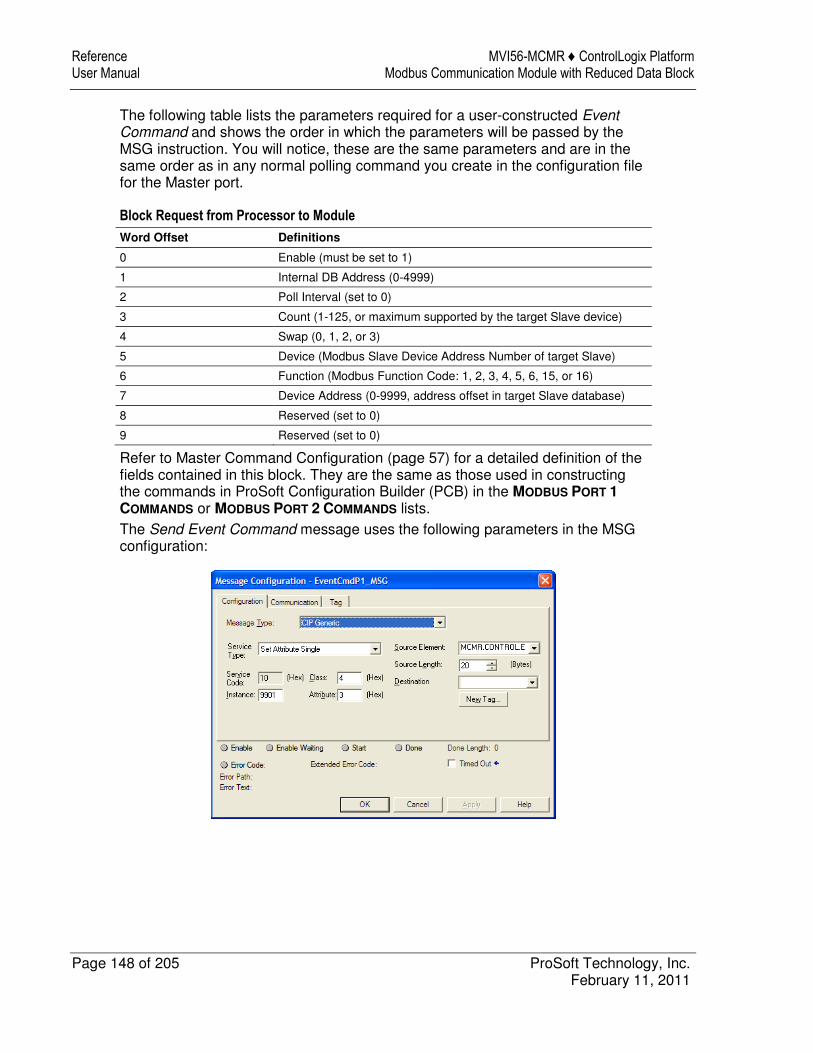
Reference MVI56-MCMR ♦ ControlLogix Platform User Manual Modbus Communication Module with Reduced Data Block
Page 148 of 205 ProSoft Technology, Inc. February 11, 2011
The following table lists the parameters required for a user-constructed Event Command and shows the order in which the parameters will be passed by the MSG instruction. You will notice, these are the same parameters and are in the same order as in any normal polling command you create in the configuration file for the Master port.
Block Request from Processor to Module
Word Offset Definitions
0 Enable (must be set to 1)
1 Internal DB Address (0-4999)
2 Poll Interval (set to 0)
3 Count (1-125, or maximum supported by the target Slave device)
4 Swap (0, 1, 2, or 3)
5 Device (Modbus Slave Device Address Number of target Slave)
6 Function (Modbus Function Code: 1, 2, 3, 4, 5, 6, 15, or 16)
7 Device Address (0-9999, address offset in target Slave database)
8 Reserved (set to 0)
9 Reserved (set to 0)
Refer to Master Command Configuration (page 57) for a detailed definition of the fields contained in this block. They are the same as those used in constructing the commands in ProSoft Configuration Builder (PCB) in the MODBUS PORT 1
COMMANDS or MODBUS PORT 2 COMMANDS lists. The Send Event Command message uses the following parameters in the MSG configuration:
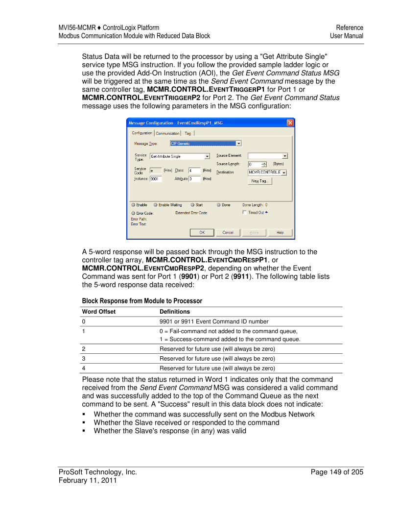
MVI56-MCMR ♦ ControlLogix Platform Reference Modbus Communication Module with Reduced Data Block User Manual
ProSoft Technology, Inc. Page 149 of 205 February 11, 2011
Status Data will be returned to the processor by using a "Get Attribute Single" service type MSG instruction. If you follow the provided sample ladder logic or use the provided Add-On Instruction (AOI), the Get Event Command Status MSG will be triggered at the same time as the Send Event Command message by the same controller tag, MCMR.CONTROL.EVENTTRIGGERP1 for Port 1 or MCMR.CONTROL.EVENTTRIGGERP2 for Port 2. The Get Event Command Status message uses the following parameters in the MSG configuration:
A 5-word response will be passed back through the MSG instruction to the controller tag array, MCMR.CONTROL.EVENTCMDRESPP1. or MCMR.CONTROL.EVENTCMDRESPP2, depending on whether the Event Command was sent for Port 1 (9901) or Port 2 (9911). The following table lists the 5-word response data received:
Block Response from Module to Processor
Word Offset Definitions
0 9901 or 9911 Event Command ID number
1 0 = Fail-command not added to the command queue, 1 = Success-command added to the command queue.
2 Reserved for future use (will always be zero)
3 Reserved for future use (will always be zero)
4 Reserved for future use (will always be zero)
Please note that the status returned in Word 1 indicates only that the command received from the Send Event Command MSG was considered a valid command and was successfully added to the top of the Command Queue as the next command to be sent. A "Success" result in this data block does not indicate: � Whether the command was successfully sent on the Modbus Network � Whether the Slave received or responded to the command � Whether the Slave's response (in any) was valid
Reference MVI56-MCMR ♦ ControlLogix Platform User Manual Modbus Communication Module with Reduced Data Block
Page 150 of 205 ProSoft Technology, Inc. February 11, 2011
There are many potential reasons why a command might fail after having been successfully added to the Command Queue. For more details, see Standard Modbus Protocol Errors or Module Communication Error Codes.
Command Control Blocks 9902 or 9912
The Command Control special function is applicable only when the module's port is configured as a Modbus Master. Command Control is best used to send commands based on special process conditions, such as emergency shutdowns, device-specific resets or any conditions which might require priority polling of a specific Slave Device. Whenever a Command Control data block is received by the module, it will insert the requested command or commands into the beginning of the Command Queue, so that the special command or commands will be sent before the next regular polling command. Sending a message (MSG instruction) containing Command Control Block Identification Code 9902 for Port 1 or 9912 for Port 2 will cause a list of from one (1) to twenty (20) commands to be placed in the Command Queue using commands from the user-created PCB Command Lists. These lists are the ones created in the MODBUS PORT 1 COMMANDS or MODBUS PORT 2 COMMANDS
sections of the PCB configuration file that was downloaded to the module and that are used by the module for normal, automatic, repetitive polling. Any command in the Command List may be given execution priority using a Command Control special function block MSG, regardless of the value set in the ENABLE parameter for that command. However, commands placed in the Command List intended for exclusive use with Command Control will most often have their ENABLE parameter set to zero(0) and will not be executed as part of a regular polling routine. Commands enabled using Command Control will be added to the Command Queue for a one-time execution each time the MSG instruction is activated. Command Control will not enable commands for normal, repeated polling if they are not already enabled in the Command List. But Command Control may be used to force commands that are enabled for normal polling to the top of the Command Queue so that they will be executed out of their normal polling sequence, as well as being executed in the normal polling order. If you use the provided sample ladder logic or Add-On Instruction (AOI), the Modbus Command parameter data required for this special function block will be placed in the controller tag array, MCMR.CONTROL.CMDCONTROLP1.CMDCONTROLDATA for Port 1 or MCMR.CONTROL.CMDCONTROLP2.CMDCONTROLDATA for Port 2. You will notice that these are 21-element arrays. The structure of the Command Control special function data block and the elements in the associated arrays is shown in the following table.
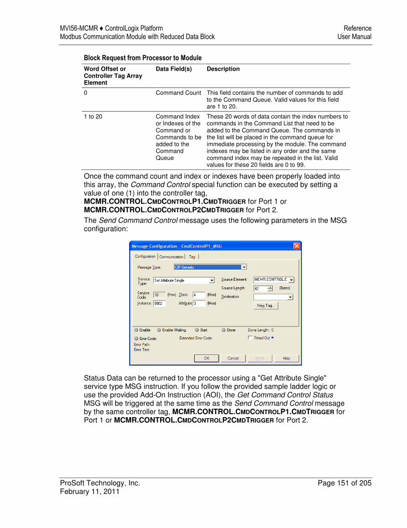
MVI56-MCMR ♦ ControlLogix Platform Reference Modbus Communication Module with Reduced Data Block User Manual
ProSoft Technology, Inc. Page 151 of 205 February 11, 2011
Block Request from Processor to Module
Word Offset or Controller Tag Array Element
Data Field(s) Description
0 Command Count This field contains the number of commands to add to the Command Queue. Valid values for this field are 1 to 20.
1 to 20 Command Index or Indexes of the Command or Commands to be added to the Command Queue
These 20 words of data contain the index numbers to commands in the Command List that need to be added to the Command Queue. The commands in the list will be placed in the command queue for immediate processing by the module. The command indexes may be listed in any order and the same command index may be repeated in the list. Valid values for these 20 fields are 0 to 99.
Once the command count and index or indexes have been properly loaded into this array, the Command Control special function can be executed by setting a value of one (1) into the controller tag, MCMR.CONTROL.CMDCONTROLP1.CMDTRIGGER for Port 1 or MCMR.CONTROL.CMDCONTROLP2CMDTRIGGER for Port 2. The Send Command Control message uses the following parameters in the MSG configuration:
Status Data can be returned to the processor using a "Get Attribute Single" service type MSG instruction. If you follow the provided sample ladder logic or use the provided Add-On Instruction (AOI), the Get Command Control Status MSG will be triggered at the same time as the Send Command Control message by the same controller tag, MCMR.CONTROL.CMDCONTROLP1.CMDTRIGGER for Port 1 or MCMR.CONTROL.CMDCONTROLP2CMDTRIGGER for Port 2.
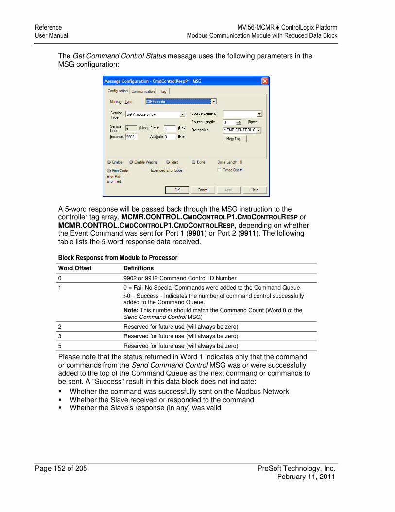
Reference MVI56-MCMR ♦ ControlLogix Platform User Manual Modbus Communication Module with Reduced Data Block
Page 152 of 205 ProSoft Technology, Inc. February 11, 2011
The Get Command Control Status message uses the following parameters in the MSG configuration:
A 5-word response will be passed back through the MSG instruction to the controller tag array, MCMR.CONTROL.CMDCONTROLP1.CMDCONTROLRESP or MCMR.CONTROL.CMDCONTROLP1.CMDCONTROLRESP, depending on whether the Event Command was sent for Port 1 (9901) or Port 2 (9911). The following table lists the 5-word response data received.
Block Response from Module to Processor
Word Offset Definitions
0 9902 or 9912 Command Control ID Number
1 0 = Fail-No Special Commands were added to the Command Queue >0 = Success - Indicates the number of command control successfully added to the Command Queue. Note: This number should match the Command Count (Word 0 of the Send Command Control MSG)
2 Reserved for future use (will always be zero)
3 Reserved for future use (will always be zero)
5 Reserved for future use (will always be zero)
Please note that the status returned in Word 1 indicates only that the command or commands from the Send Command Control MSG was or were successfully added to the top of the Command Queue as the next command or commands to be sent. A "Success" result in this data block does not indicate: � Whether the command was successfully sent on the Modbus Network � Whether the Slave received or responded to the command � Whether the Slave's response (in any) was valid
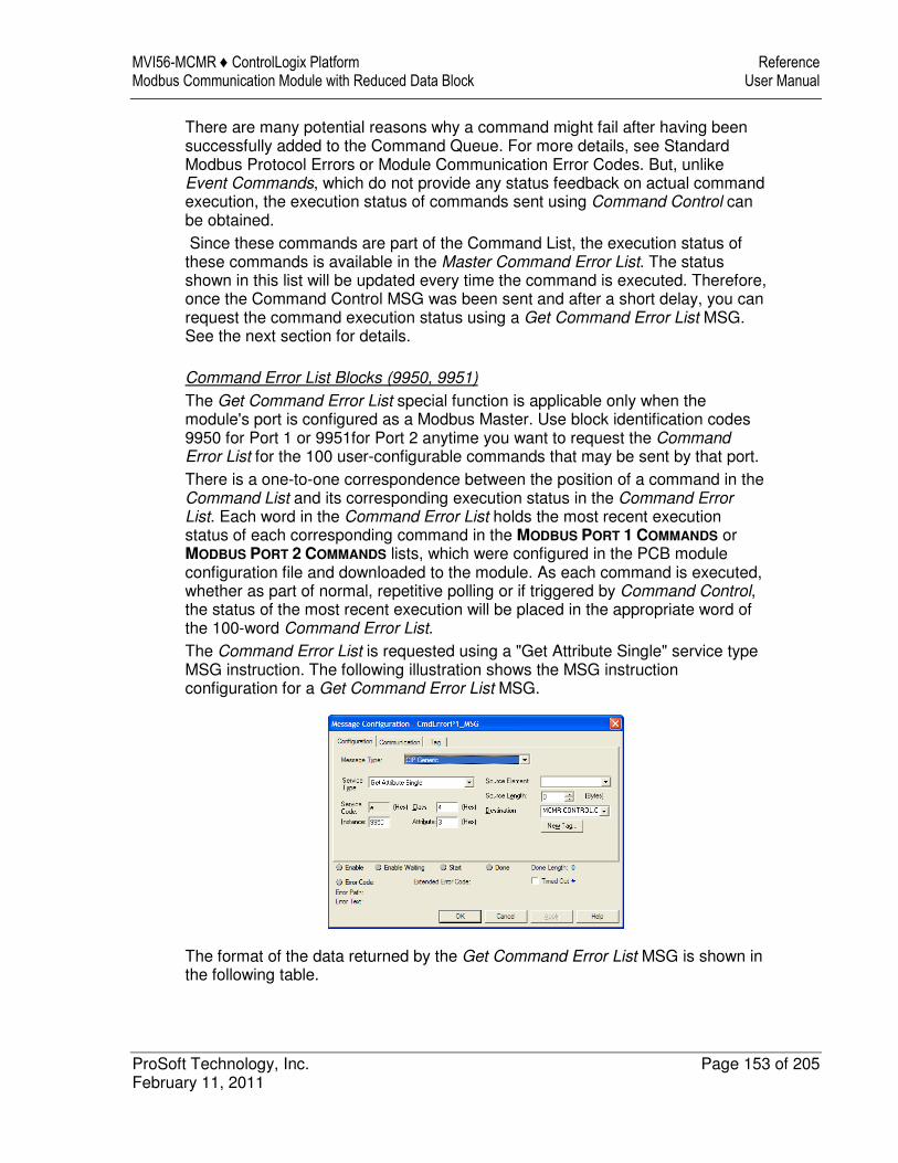
MVI56-MCMR ♦ ControlLogix Platform Reference Modbus Communication Module with Reduced Data Block User Manual
ProSoft Technology, Inc. Page 153 of 205 February 11, 2011
There are many potential reasons why a command might fail after having been successfully added to the Command Queue. For more details, see Standard Modbus Protocol Errors or Module Communication Error Codes. But, unlike Event Commands, which do not provide any status feedback on actual command execution, the execution status of commands sent using Command Control can be obtained. Since these commands are part of the Command List, the execution status of these commands is available in the Master Command Error List. The status shown in this list will be updated every time the command is executed. Therefore, once the Command Control MSG was been sent and after a short delay, you can request the command execution status using a Get Command Error List MSG. See the next section for details.
Command Error List Blocks (9950, 9951)
The Get Command Error List special function is applicable only when the module's port is configured as a Modbus Master. Use block identification codes 9950 for Port 1 or 9951for Port 2 anytime you want to request the Command Error List for the 100 user-configurable commands that may be sent by that port. There is a one-to-one correspondence between the position of a command in the Command List and its corresponding execution status in the Command Error List. Each word in the Command Error List holds the most recent execution status of each corresponding command in the MODBUS PORT 1 COMMANDS or MODBUS PORT 2 COMMANDS lists, which were configured in the PCB module configuration file and downloaded to the module. As each command is executed, whether as part of normal, repetitive polling or if triggered by Command Control, the status of the most recent execution will be placed in the appropriate word of the 100-word Command Error List. The Command Error List is requested using a "Get Attribute Single" service type MSG instruction. The following illustration shows the MSG instruction configuration for a Get Command Error List MSG.
The format of the data returned by the Get Command Error List MSG is shown in the following table.
Reference MVI56-MCMR ♦ ControlLogix Platform User Manual Modbus Communication Module with Reduced Data Block
Page 154 of 205 ProSoft Technology, Inc. February 11, 2011
Block Response from Module to Processor
Word Offset Data Field(s) Description
0 Number of Commands to report
This field contains the number of commands to report in the response message. The value is always 100.
1 Start Index of First Command
This field always contains a 0. The status of all 100 possible commands will be returned, starting with Command Index 0, the first command in the Command List.
2 to 102 Command Error List
Each word of this area contains the last execution status value recorded for the command. The order of status words is the same as the order of commands in the Command List
A status value of zero (0) in the Command Error List indicates either that the corresponding command is not used or that it has been executed successfully. Any non-zero value found in this list indicates that some type of error was encountered while trying to execute the corresponding command. There are many potential reasons why a command might fail. For more details, see Standard Modbus Protocol Errors or Module Communication Error Codes.
Slave Status Blocks (9960, 9961)
The Get Slave Status List special function is available only when the module's port is configured as a Modbus Master. Use block identification codes 9960 for Port 1 or 9961 for Port 2 to request the current polling state of each Slave device that could be polled by a Master port. The results returned in this list have a one-to-one correspondence with the 248 possible Modbus Slave Device Address values, 0-247. Each word in the Slave Status List corresponds to a single Modbus Slave Device Address. This list is updated each time the Master driver attempts to poll a specific Modbus Slave Device; but gives very little information regarding the success or failure of that poll attempt. Therefore, this list is not very useful for determining general communications health, for creating communication failure alarms, or for troubleshooting network problems. A better tool for those needs is the Command Error List. The Get Slave Status List message uses the "Get Attribute Single" service type MSG instruction. The format of the data returned by the MSG is shown in the following table.
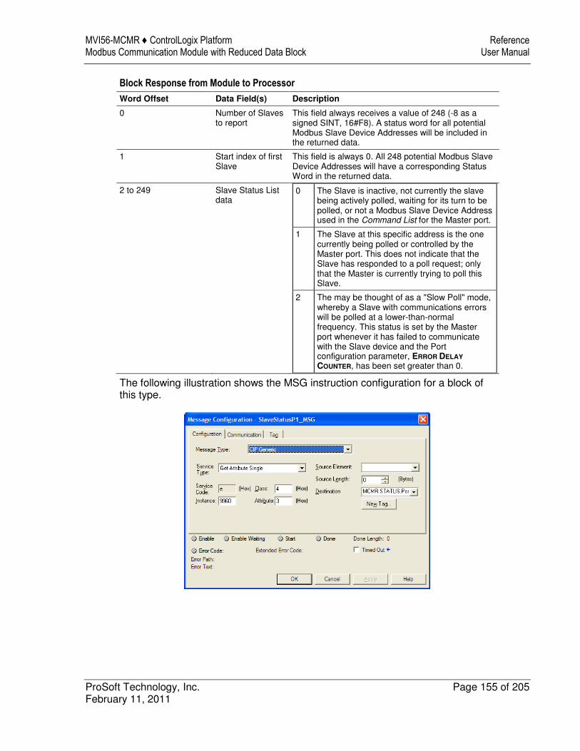
MVI56-MCMR ♦ ControlLogix Platform Reference Modbus Communication Module with Reduced Data Block User Manual
ProSoft Technology, Inc. Page 155 of 205 February 11, 2011
Block Response from Module to Processor
Word Offset Data Field(s) Description
0 Number of Slaves to report
This field always receives a value of 248 (-8 as a signed SINT, 16#F8). A status word for all potential Modbus Slave Device Addresses will be included in the returned data.
1 Start index of first Slave
This field is always 0. All 248 potential Modbus Slave Device Addresses will have a corresponding Status Word in the returned data.
2 to 249 Slave Status List data
0 The Slave is inactive, not currently the slave being actively polled, waiting for its turn to be polled, or not a Modbus Slave Device Address used in the Command List for the Master port.
1 The Slave at this specific address is the one currently being polled or controlled by the Master port. This does not indicate that the Slave has responded to a poll request; only that the Master is currently trying to poll this Slave.
2 The may be thought of as a "Slow Poll" mode, whereby a Slave with communications errors will be polled at a lower-than-normal frequency. This status is set by the Master port whenever it has failed to communicate with the Slave device and the Port configuration parameter, ERROR DELAY
COUNTER, has been set greater than 0.
The following illustration shows the MSG instruction configuration for a block of this type.
Reference MVI56-MCMR ♦ ControlLogix Platform User Manual Modbus Communication Module with Reduced Data Block
Page 156 of 205 ProSoft Technology, Inc. February 11, 2011
Warm Boot Block (9998)
The Warm Boot special function is used to restart the module application from within processor logic. This allows the module to be restarted without removing it from the chassis or removing power from the chassis. Restarting or "rebooting" the module will momentarily interrupt normal module operation, such as Modbus polling and backplane data transfers. It will also clear and reset all module diagnostic counters and user database memory. This special function is one of the few that is sent in the Output Image Write Data block instead of a MSG instruction. Therefore, the effect of triggering a Warm Boot is almost immediate. If you follow the sample ladder logic or AOI, the block identification code 9998 for the Warm Boot special function is embedded in the logic that formulates the Write Data block to be sent to the module in the Output Image. You can activate this special block logic by setting the controller tag, MCMR.CONTROL.WARMBOOT, to a value of 1. This will force an immediate module reboot. The following table describes the format of the Warm Boot data block constructed by the processor.
Block Request from Processor to Module
Word Offset Description Length
0 9998 1
1 to 41 Spare 41
Warm Boot and Cold Boot special functions are almost identical in what they do to reboot the module. The main difference between the two is that the Warm Boot restarts the internal firmware application without interrupting backplane power to the module. Therefore, a Warm Boot will complete and the module will return to normal operation a few seconds faster than when a Cold Boot is used. However, if the module is not operating correctly and a Warm Boot does not completely restore normal operation, a Cold Boot may be required and may be more effective at clearing errors and restarting the application.
Cold Boot Block (9999)
The Cold Boot special function is used to restart the module application from within processor logic. This allows the module to be restarted without removing it from the chassis or removing power from the chassis. Restarting or "rebooting" the module will momentarily interrupt normal module operation, such as Modbus polling and backplane data transfers. It will also clear and reset all module diagnostic counters and user database memory. This special function is one of the few that is sent in the Output Image Write Data block instead of a MSG instruction. Therefore, the effect of triggering a Cold Boot is almost immediate.
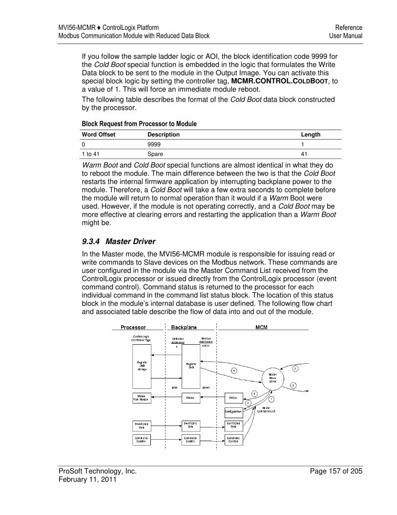
MVI56-MCMR ♦ ControlLogix Platform Reference Modbus Communication Module with Reduced Data Block User Manual
ProSoft Technology, Inc. Page 157 of 205 February 11, 2011
If you follow the sample ladder logic or AOI, the block identification code 9999 for the Cold Boot special function is embedded in the logic that formulates the Write Data block to be sent to the module in the Output Image. You can activate this special block logic by setting the controller tag, MCMR.CONTROL.COLDBOOT, to a value of 1. This will force an immediate module reboot. The following table describes the format of the Cold Boot data block constructed by the processor.
Block Request from Processor to Module
Word Offset Description Length
0 9999 1
1 to 41 Spare 41
Warm Boot and Cold Boot special functions are almost identical in what they do to reboot the module. The main difference between the two is that the Cold Boot restarts the internal firmware application by interrupting backplane power to the module. Therefore, a Cold Boot will take a few extra seconds to complete before the module will return to normal operation than it would if a Warm Boot were used. However, if the module is not operating correctly, and a Cold Boot may be more effective at clearing errors and restarting the application than a Warm Boot might be.
9.3.4 Master Driver
In the Master mode, the MVI56-MCMR module is responsible for issuing read or write commands to Slave devices on the Modbus network. These commands are user configured in the module via the Master Command List received from the ControlLogix processor or issued directly from the ControlLogix processor (event command control). Command status is returned to the processor for each individual command in the command list status block. The location of this status block in the module’s internal database is user defined. The following flow chart and associated table describe the flow of data into and out of the module.
Reference MVI56-MCMR ♦ ControlLogix Platform User Manual Modbus Communication Module with Reduced Data Block
Page 158 of 205 ProSoft Technology, Inc. February 11, 2011
1 The Master driver obtains configuration data from the Compact Flash Disk. The configuration data obtained includes general module configuration data as well as the Master Command List. These values are used by the Master driver to determine the type of commands to be issued to Modbus Slave Devices on the Modbus network
2 After configuration, the Master driver begins transmitting read and/or write commands to the Modbus Slave Devices on the network. If writing data to a Modbus Slave Device, the data to send in the write command is obtained from the module’s internal database.
3 Presuming successful processing by the Modbus Slave Device specified in the command, a response message is received into the Master driver for processing.
4 If the command was a command to read data, the data received from the Modbus Slave Device is passed into the module’s internal database.
5 Status is returned to the ControlLogix processor for each command in the Master Command List (page 158).
Refer to Configuration as a Modbus Master (page 51) for a description of the parameters required to define the virtual Modbus Master port. Command Control Blocks describes the structure and content of each command.
Important: Take care when constructing each command in the list for predictable operation of the module. If two commands write to the same internal database address of the module, the results will not be as desired. All commands containing invalid data are ignored by the module.
Master Command List
In order to function in the Master Mode, you must define the module’s Master Command List. This list contains up to 100 individual entries, with each entry containing the information required to construct a valid command. A valid command includes the following items: � Command enable mode: (0) disabled, (1) continuous or (2) conditional � Slave Node Address � Command Type: Read or Write up to 125 words (16000 bits) per command � Database Source and Destination Register Address: The addresses where
data will be written or read. � Count: The number of words to be transferred - 1 to 125 on FC 3, 4, or 16.
Select the number of bits on FC 1, 2, 15. As the list is read in from the processor and as the commands are processed, an error value is maintained in the module for each command. This error list can be transferred to the processor. The following tables describe the error codes generated by the module.
Note: 125 words is the maximum count allowed by the MODBUS protocol. Some field devices may support less than the full 125 words. Check with your device manufacturer for the maximum count supported by your particular slave.
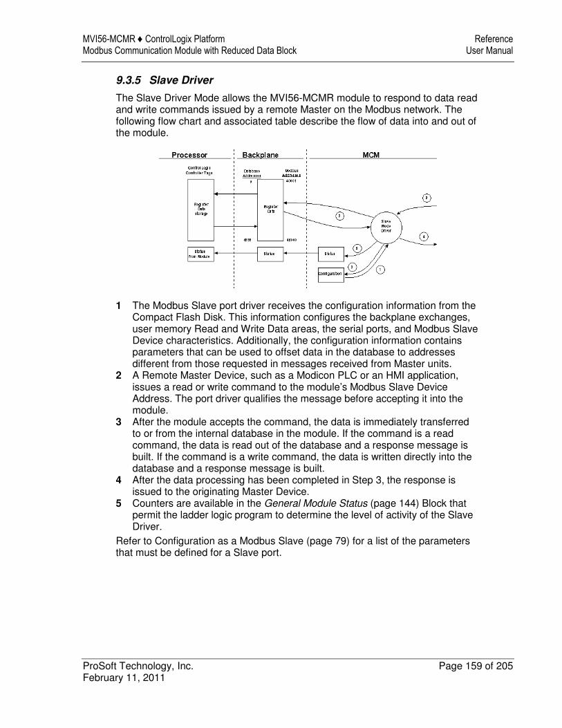
MVI56-MCMR ♦ ControlLogix Platform Reference Modbus Communication Module with Reduced Data Block User Manual
ProSoft Technology, Inc. Page 159 of 205 February 11, 2011
9.3.5 Slave Driver
The Slave Driver Mode allows the MVI56-MCMR module to respond to data read and write commands issued by a remote Master on the Modbus network. The following flow chart and associated table describe the flow of data into and out of the module.
1 The Modbus Slave port driver receives the configuration information from the Compact Flash Disk. This information configures the backplane exchanges, user memory Read and Write Data areas, the serial ports, and Modbus Slave Device characteristics. Additionally, the configuration information contains parameters that can be used to offset data in the database to addresses different from those requested in messages received from Master units.
2 A Remote Master Device, such as a Modicon PLC or an HMI application, issues a read or write command to the module’s Modbus Slave Device Address. The port driver qualifies the message before accepting it into the module.
3 After the module accepts the command, the data is immediately transferred to or from the internal database in the module. If the command is a read command, the data is read out of the database and a response message is built. If the command is a write command, the data is written directly into the database and a response message is built.
4 After the data processing has been completed in Step 3, the response is issued to the originating Master Device.
5 Counters are available in the General Module Status (page 144) Block that permit the ladder logic program to determine the level of activity of the Slave Driver.
Refer to Configuration as a Modbus Slave (page 79) for a list of the parameters that must be defined for a Slave port.
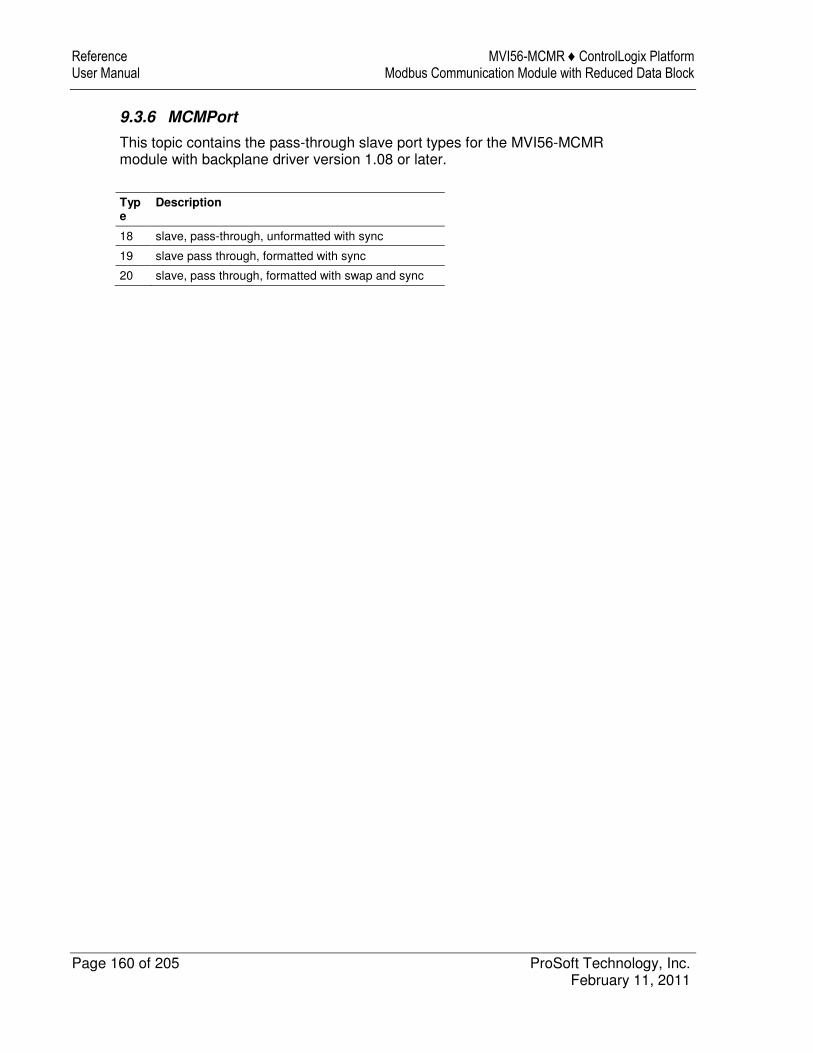
Reference MVI56-MCMR ♦ ControlLogix Platform User Manual Modbus Communication Module with Reduced Data Block
Page 160 of 205 ProSoft Technology, Inc. February 11, 2011
9.3.6 MCMPort
This topic contains the pass-through slave port types for the MVI56-MCMR module with backplane driver version 1.08 or later.
Type
Description
18 slave, pass-through, unformatted with sync
19 slave pass through, formatted with sync
20 slave, pass through, formatted with swap and sync
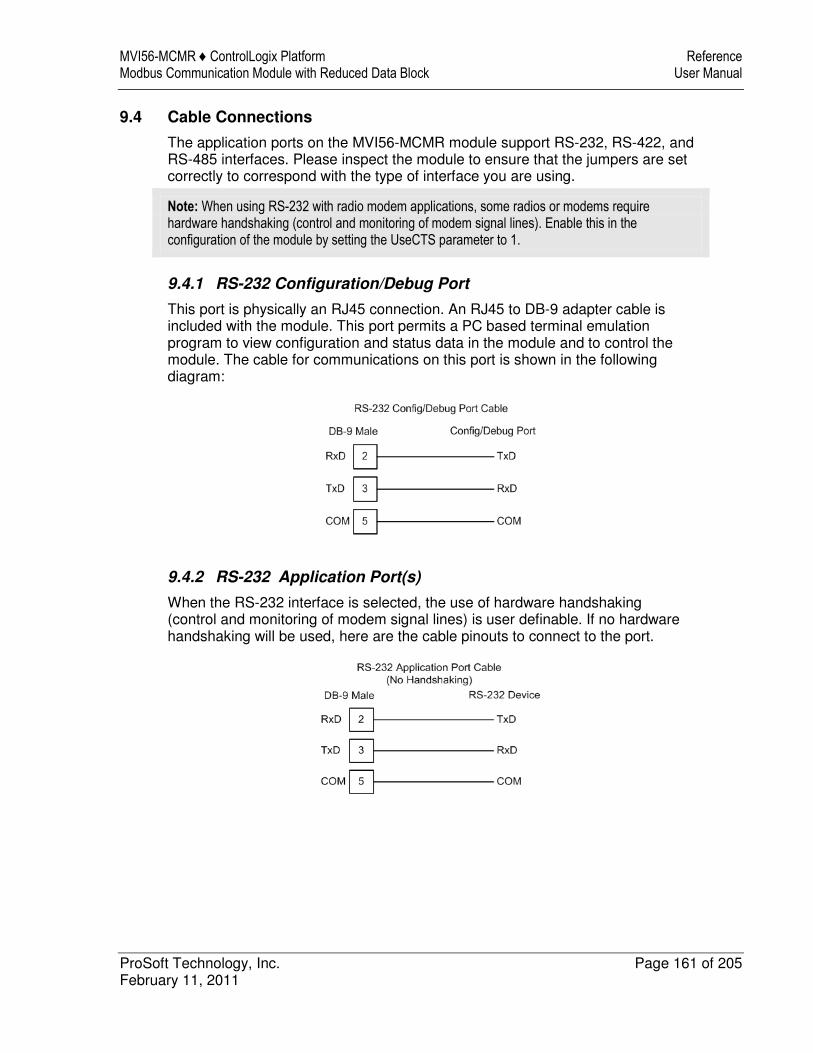
MVI56-MCMR ♦ ControlLogix Platform Reference Modbus Communication Module with Reduced Data Block User Manual
ProSoft Technology, Inc. Page 161 of 205 February 11, 2011
9.4 Cable Connections
The application ports on the MVI56-MCMR module support RS-232, RS-422, and RS-485 interfaces. Please inspect the module to ensure that the jumpers are set correctly to correspond with the type of interface you are using.
Note: When using RS-232 with radio modem applications, some radios or modems require hardware handshaking (control and monitoring of modem signal lines). Enable this in the configuration of the module by setting the UseCTS parameter to 1.
9.4.1 RS-232 Configuration/Debug Port
This port is physically an RJ45 connection. An RJ45 to DB-9 adapter cable is included with the module. This port permits a PC based terminal emulation program to view configuration and status data in the module and to control the module. The cable for communications on this port is shown in the following diagram:
9.4.2 RS-232 Application Port(s)
When the RS-232 interface is selected, the use of hardware handshaking (control and monitoring of modem signal lines) is user definable. If no hardware handshaking will be used, here are the cable pinouts to connect to the port.
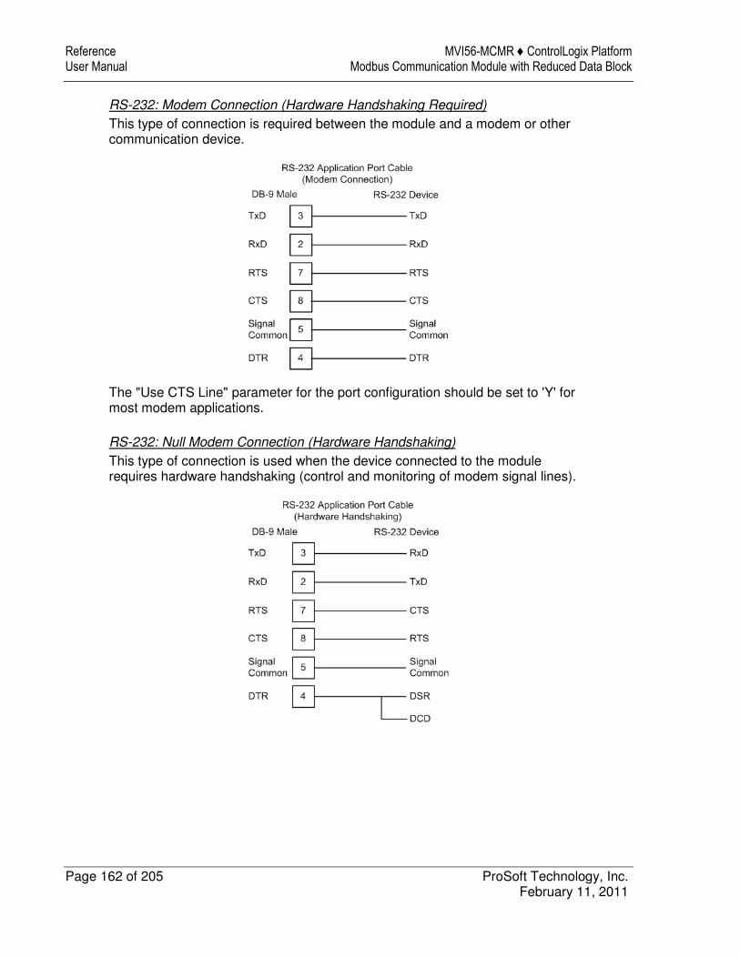
Reference MVI56-MCMR ♦ ControlLogix Platform User Manual Modbus Communication Module with Reduced Data Block
Page 162 of 205 ProSoft Technology, Inc. February 11, 2011
RS-232: Modem Connection (Hardware Handshaking Required)
This type of connection is required between the module and a modem or other communication device.
The "Use CTS Line" parameter for the port configuration should be set to 'Y' for most modem applications.
RS-232: Null Modem Connection (Hardware Handshaking)
This type of connection is used when the device connected to the module requires hardware handshaking (control and monitoring of modem signal lines).
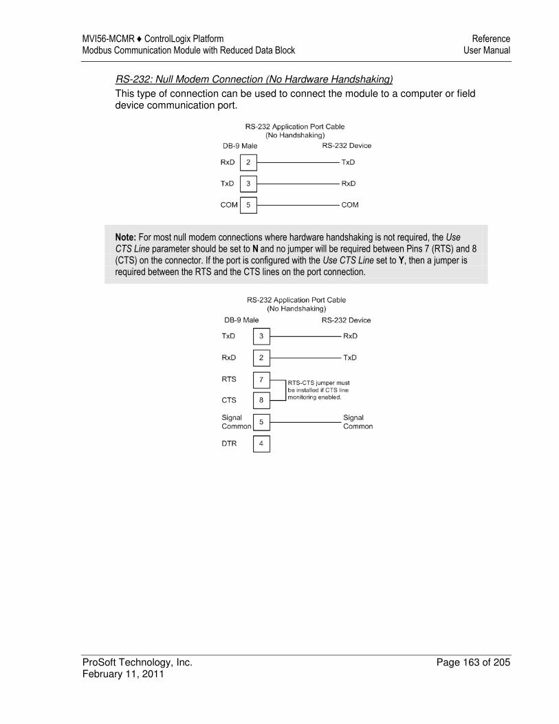
MVI56-MCMR ♦ ControlLogix Platform Reference Modbus Communication Module with Reduced Data Block User Manual
ProSoft Technology, Inc. Page 163 of 205 February 11, 2011
RS-232: Null Modem Connection (No Hardware Handshaking)
This type of connection can be used to connect the module to a computer or field device communication port.
Note: For most null modem connections where hardware handshaking is not required, the Use CTS Line parameter should be set to N and no jumper will be required between Pins 7 (RTS) and 8 (CTS) on the connector. If the port is configured with the Use CTS Line set to Y, then a jumper is required between the RTS and the CTS lines on the port connection.
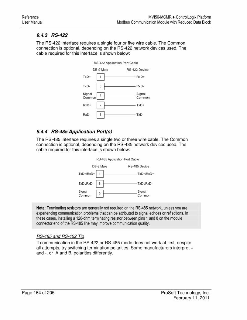
Reference MVI56-MCMR ♦ ControlLogix Platform User Manual Modbus Communication Module with Reduced Data Block
Page 164 of 205 ProSoft Technology, Inc. February 11, 2011
9.4.3 RS-422
The RS-422 interface requires a single four or five wire cable. The Common connection is optional, depending on the RS-422 network devices used. The cable required for this interface is shown below:
9.4.4 RS-485 Application Port(s)
The RS-485 interface requires a single two or three wire cable. The Common connection is optional, depending on the RS-485 network devices used. The cable required for this interface is shown below:
Note: Terminating resistors are generally not required on the RS-485 network, unless you are experiencing communication problems that can be attributed to signal echoes or reflections. In these cases, installing a 120-ohm terminating resistor between pins 1 and 8 on the module connector end of the RS-485 line may improve communication quality.
RS-485 and RS-422 Tip
If communication in the RS-422 or RS-485 mode does not work at first, despite all attempts, try switching termination polarities. Some manufacturers interpret + and -, or A and B, polarities differently.
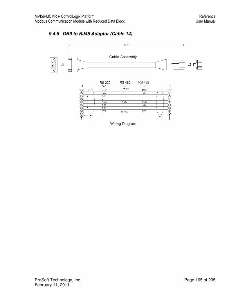
MVI56-MCMR ♦ ControlLogix Platform Reference Modbus Communication Module with Reduced Data Block User Manual
ProSoft Technology, Inc. Page 165 of 205 February 11, 2011
9.4.5 DB9 to RJ45 Adaptor (Cable 14)
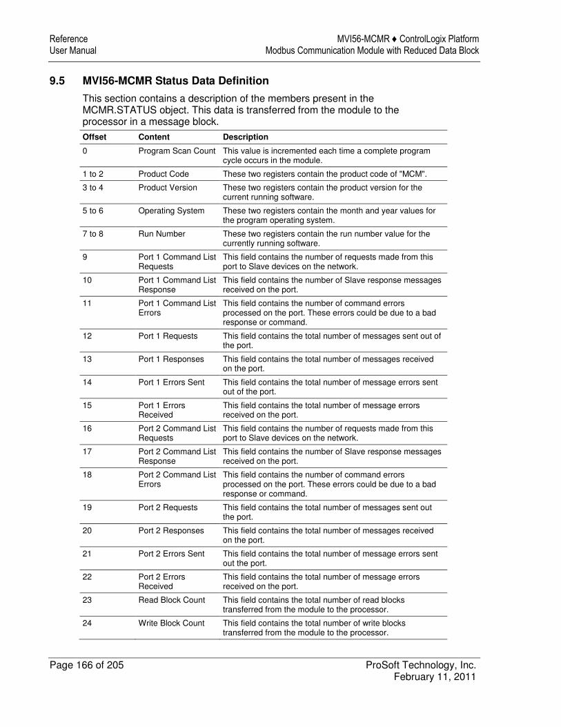
Reference MVI56-MCMR ♦ ControlLogix Platform User Manual Modbus Communication Module with Reduced Data Block
Page 166 of 205 ProSoft Technology, Inc. February 11, 2011
9.5 MVI56-MCMR Status Data Definition
This section contains a description of the members present in the MCMR.STATUS object. This data is transferred from the module to the processor in a message block.
Offset Content Description
0 Program Scan Count This value is incremented each time a complete program cycle occurs in the module.
1 to 2 Product Code These two registers contain the product code of "MCM".
3 to 4 Product Version These two registers contain the product version for the current running software.
5 to 6 Operating System These two registers contain the month and year values for the program operating system.
7 to 8 Run Number These two registers contain the run number value for the currently running software.
9 Port 1 Command List Requests
This field contains the number of requests made from this port to Slave devices on the network.
10 Port 1 Command List Response
This field contains the number of Slave response messages received on the port.
11 Port 1 Command List Errors
This field contains the number of command errors processed on the port. These errors could be due to a bad response or command.
12 Port 1 Requests This field contains the total number of messages sent out of the port.
13 Port 1 Responses This field contains the total number of messages received on the port.
14 Port 1 Errors Sent This field contains the total number of message errors sent out of the port.
15 Port 1 Errors Received
This field contains the total number of message errors received on the port.
16 Port 2 Command List Requests
This field contains the number of requests made from this port to Slave devices on the network.
17 Port 2 Command List Response
This field contains the number of Slave response messages received on the port.
18 Port 2 Command List Errors
This field contains the number of command errors processed on the port. These errors could be due to a bad response or command.
19 Port 2 Requests This field contains the total number of messages sent out the port.
20 Port 2 Responses This field contains the total number of messages received on the port.
21 Port 2 Errors Sent This field contains the total number of message errors sent out the port.
22 Port 2 Errors Received
This field contains the total number of message errors received on the port.
23 Read Block Count This field contains the total number of read blocks transferred from the module to the processor.
24 Write Block Count This field contains the total number of write blocks transferred from the module to the processor.
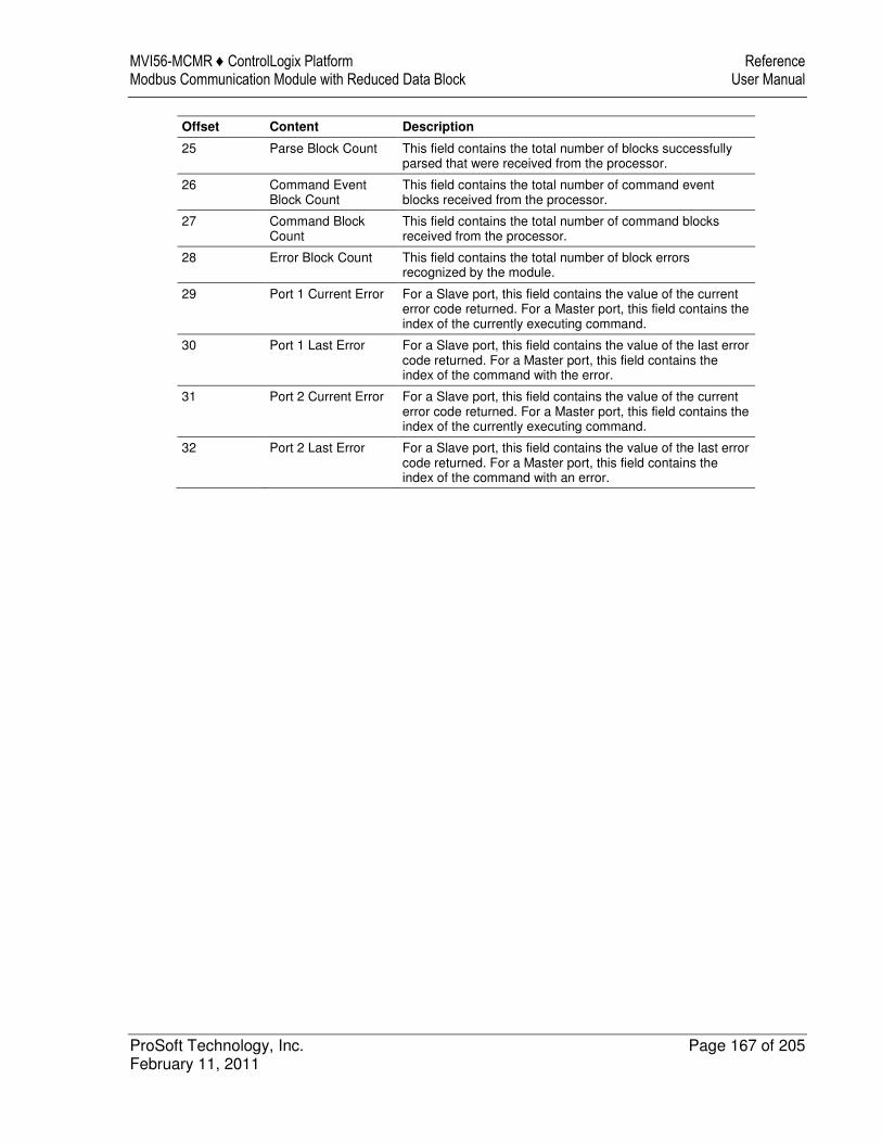
MVI56-MCMR ♦ ControlLogix Platform Reference Modbus Communication Module with Reduced Data Block User Manual
ProSoft Technology, Inc. Page 167 of 205 February 11, 2011
Offset Content Description
25 Parse Block Count This field contains the total number of blocks successfully parsed that were received from the processor.
26 Command Event Block Count
This field contains the total number of command event blocks received from the processor.
27 Command Block Count
This field contains the total number of command blocks received from the processor.
28 Error Block Count This field contains the total number of block errors recognized by the module.
29 Port 1 Current Error For a Slave port, this field contains the value of the current error code returned. For a Master port, this field contains the index of the currently executing command.
30 Port 1 Last Error For a Slave port, this field contains the value of the last error code returned. For a Master port, this field contains the index of the command with the error.
31 Port 2 Current Error For a Slave port, this field contains the value of the current error code returned. For a Master port, this field contains the index of the currently executing command.
32 Port 2 Last Error For a Slave port, this field contains the value of the last error code returned. For a Master port, this field contains the index of the command with an error.
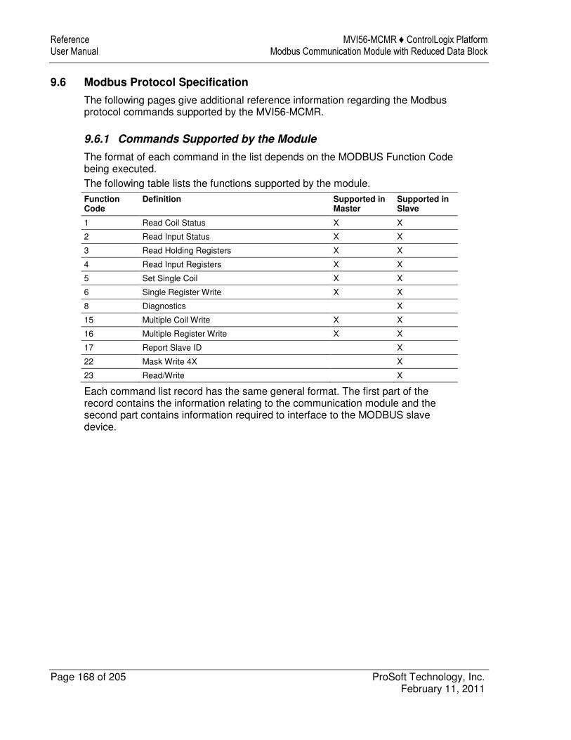
Reference MVI56-MCMR ♦ ControlLogix Platform User Manual Modbus Communication Module with Reduced Data Block
Page 168 of 205 ProSoft Technology, Inc. February 11, 2011
9.6 Modbus Protocol Specification
The following pages give additional reference information regarding the Modbus protocol commands supported by the MVI56-MCMR.
9.6.1 Commands Supported by the Module
The format of each command in the list depends on the MODBUS Function Code being executed. The following table lists the functions supported by the module.
Function Code
Definition Supported in Master
Supported in Slave
1 Read Coil Status X X
2 Read Input Status X X
3 Read Holding Registers X X
4 Read Input Registers X X
5 Set Single Coil X X
6 Single Register Write X X
8 Diagnostics X
15 Multiple Coil Write X X
16 Multiple Register Write X X
17 Report Slave ID X
22 Mask Write 4X X
23 Read/Write X
Each command list record has the same general format. The first part of the record contains the information relating to the communication module and the second part contains information required to interface to the MODBUS slave device.
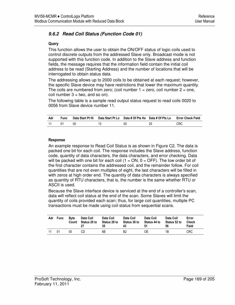
MVI56-MCMR ♦ ControlLogix Platform Reference Modbus Communication Module with Reduced Data Block User Manual
ProSoft Technology, Inc. Page 169 of 205 February 11, 2011
9.6.2 Read Coil Status (Function Code 01)
Query
This function allows the user to obtain the ON/OFF status of logic coils used to control discrete outputs from the addressed Slave only. Broadcast mode is not supported with this function code. In addition to the Slave address and function fields, the message requires that the information field contain the initial coil address to be read (Starting Address) and the number of locations that will be interrogated to obtain status data. The addressing allows up to 2000 coils to be obtained at each request; however, the specific Slave device may have restrictions that lower the maximum quantity. The coils are numbered from zero; (coil number 1 = zero, coil number 2 = one, coil number 3 = two, and so on). The following table is a sample read output status request to read coils 0020 to 0056 from Slave device number 11.
Adr Func Data Start Pt Hi Data Start Pt Lo Data # Of Pts Ho Data # Of Pts Lo Error Check Field
11 01 00 13 00 25 CRC
Response
An example response to Read Coil Status is as shown in Figure C2. The data is packed one bit for each coil. The response includes the Slave address, function code, quantity of data characters, the data characters, and error checking. Data will be packed with one bit for each coil (1 = ON, 0 = OFF). The low order bit of the first character contains the addressed coil, and the remainder follow. For coil quantities that are not even multiples of eight, the last characters will be filled in with zeros at high order end. The quantity of data characters is always specified as quantity of RTU characters, that is, the number is the same whether RTU or ASCII is used. Because the Slave interface device is serviced at the end of a controller's scan, data will reflect coil status at the end of the scan. Some Slaves will limit the quantity of coils provided each scan; thus, for large coil quantities, multiple PC transactions must be made using coil status from sequential scans.
Adr Func Byte Count
Data Coil Status 20 to 27
Data Coil Status 28 to 35
Data Coil Status 36 to 43
Data Coil Status 44 to 51
Data Coil Status 52 to 56
Error Check Field
11 01 05 CD 6B B2 OE 1B CRC
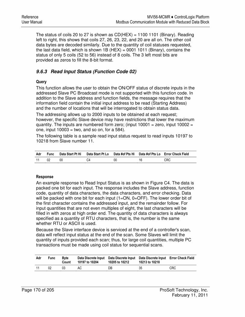
Reference MVI56-MCMR ♦ ControlLogix Platform User Manual Modbus Communication Module with Reduced Data Block
Page 170 of 205 ProSoft Technology, Inc. February 11, 2011
The status of coils 20 to 27 is shown as CD(HEX) = 1100 1101 (Binary). Reading left to right, this shows that coils 27, 26, 23, 22, and 20 are all on. The other coil data bytes are decoded similarly. Due to the quantity of coil statuses requested, the last data field, which is shown 1B (HEX) = 0001 1011 (Binary), contains the status of only 5 coils (52 to 56) instead of 8 coils. The 3 left most bits are provided as zeros to fill the 8-bit format.
9.6.3 Read Input Status (Function Code 02)
Query
This function allows the user to obtain the ON/OFF status of discrete inputs in the addressed Slave PC Broadcast mode is not supported with this function code. In addition to the Slave address and function fields, the message requires that the information field contain the initial input address to be read (Starting Address) and the number of locations that will be interrogated to obtain status data. The addressing allows up to 2000 inputs to be obtained at each request; however, the specific Slave device may have restrictions that lower the maximum quantity. The inputs are numbered form zero; (input 10001 = zero, input 10002 = one, input 10003 = two, and so on, for a 584). The following table is a sample read input status request to read inputs 10197 to 10218 from Slave number 11.
Adr Func Data Start Pt Hi Data Start Pt Lo Data #of Pts Hi Data #of Pts Lo Error Check Field
11 02 00 C4 00 16 CRC
Response
An example response to Read Input Status is as shown in Figure C4. The data is packed one bit for each input. The response includes the Slave address, function code, quantity of data characters, the data characters, and error checking. Data will be packed with one bit for each input (1=ON, 0=OFF). The lower order bit of the first character contains the addressed input, and the remainder follow. For input quantities that are not even multiples of eight, the last characters will be filled in with zeros at high order end. The quantity of data characters is always specified as a quantity of RTU characters, that is, the number is the same whether RTU or ASCII is used. Because the Slave interface device is serviced at the end of a controller's scan, data will reflect input status at the end of the scan. Some Slaves will limit the quantity of inputs provided each scan; thus, for large coil quantities, multiple PC transactions must be made using coil status for sequential scans.
Adr Func Byte Count
Data Discrete Input 10197 to 10204
Data Discrete Input 10205 to 10212
Data Discrete Input 10213 to 10218
Error Check Field
11 02 03 AC DB 35 CRC
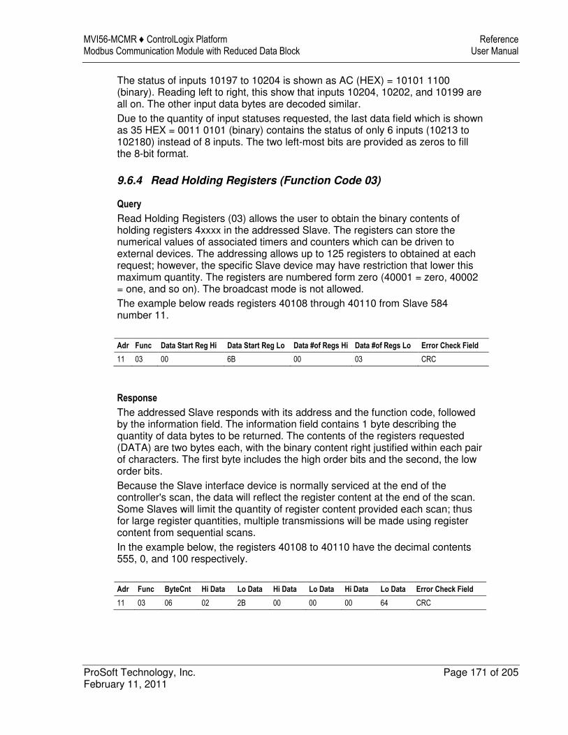
MVI56-MCMR ♦ ControlLogix Platform Reference Modbus Communication Module with Reduced Data Block User Manual
ProSoft Technology, Inc. Page 171 of 205 February 11, 2011
The status of inputs 10197 to 10204 is shown as AC (HEX) = 10101 1100 (binary). Reading left to right, this show that inputs 10204, 10202, and 10199 are all on. The other input data bytes are decoded similar. Due to the quantity of input statuses requested, the last data field which is shown as 35 HEX = 0011 0101 (binary) contains the status of only 6 inputs (10213 to 102180) instead of 8 inputs. The two left-most bits are provided as zeros to fill the 8-bit format.
9.6.4 Read Holding Registers (Function Code 03)
Query
Read Holding Registers (03) allows the user to obtain the binary contents of holding registers 4xxxx in the addressed Slave. The registers can store the numerical values of associated timers and counters which can be driven to external devices. The addressing allows up to 125 registers to obtained at each request; however, the specific Slave device may have restriction that lower this maximum quantity. The registers are numbered form zero (40001 = zero, 40002 = one, and so on). The broadcast mode is not allowed. The example below reads registers 40108 through 40110 from Slave 584 number 11.
Adr Func Data Start Reg Hi Data Start Reg Lo Data #of Regs Hi Data #of Regs Lo Error Check Field
11 03 00 6B 00 03 CRC
Response
The addressed Slave responds with its address and the function code, followed by the information field. The information field contains 1 byte describing the quantity of data bytes to be returned. The contents of the registers requested (DATA) are two bytes each, with the binary content right justified within each pair of characters. The first byte includes the high order bits and the second, the low order bits. Because the Slave interface device is normally serviced at the end of the controller's scan, the data will reflect the register content at the end of the scan. Some Slaves will limit the quantity of register content provided each scan; thus for large register quantities, multiple transmissions will be made using register content from sequential scans. In the example below, the registers 40108 to 40110 have the decimal contents 555, 0, and 100 respectively.
Adr Func ByteCnt Hi Data Lo Data Hi Data Lo Data Hi Data Lo Data Error Check Field
11 03 06 02 2B 00 00 00 64 CRC
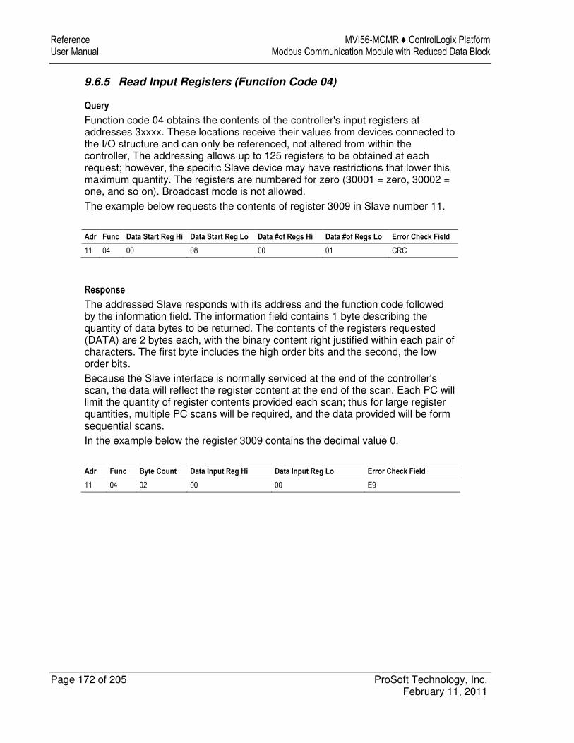
Reference MVI56-MCMR ♦ ControlLogix Platform User Manual Modbus Communication Module with Reduced Data Block
Page 172 of 205 ProSoft Technology, Inc. February 11, 2011
9.6.5 Read Input Registers (Function Code 04)
Query
Function code 04 obtains the contents of the controller's input registers at addresses 3xxxx. These locations receive their values from devices connected to the I/O structure and can only be referenced, not altered from within the controller, The addressing allows up to 125 registers to be obtained at each request; however, the specific Slave device may have restrictions that lower this maximum quantity. The registers are numbered for zero (30001 = zero, 30002 = one, and so on). Broadcast mode is not allowed. The example below requests the contents of register 3009 in Slave number 11.
Adr Func Data Start Reg Hi Data Start Reg Lo Data #of Regs Hi Data #of Regs Lo Error Check Field
11 04 00 08 00 01 CRC
Response
The addressed Slave responds with its address and the function code followed by the information field. The information field contains 1 byte describing the quantity of data bytes to be returned. The contents of the registers requested (DATA) are 2 bytes each, with the binary content right justified within each pair of characters. The first byte includes the high order bits and the second, the low order bits. Because the Slave interface is normally serviced at the end of the controller's scan, the data will reflect the register content at the end of the scan. Each PC will limit the quantity of register contents provided each scan; thus for large register quantities, multiple PC scans will be required, and the data provided will be form sequential scans. In the example below the register 3009 contains the decimal value 0.
Adr Func Byte Count Data Input Reg Hi Data Input Reg Lo Error Check Field
11 04 02 00 00 E9
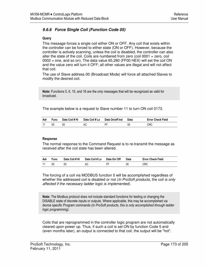
MVI56-MCMR ♦ ControlLogix Platform Reference Modbus Communication Module with Reduced Data Block User Manual
ProSoft Technology, Inc. Page 173 of 205 February 11, 2011
9.6.6 Force Single Coil (Function Code 05)
Query
This message forces a single coil either ON or OFF. Any coil that exists within the controller can be forced to either state (ON or OFF). However, because the controller is actively scanning, unless the coil is disabled, the controller can also alter the state of the coil. Coils are numbered from zero (coil 0001 = zero, coil 0002 = one, and so on). The data value 65,280 (FF00 HEX) will set the coil ON and the value zero will turn it OFF; all other values are illegal and will not affect that coil. The use of Slave address 00 (Broadcast Mode) will force all attached Slaves to modify the desired coil.
Note: Functions 5, 6, 15, and 16 are the only messages that will be recognized as valid for broadcast.
The example below is a request to Slave number 11 to turn ON coil 0173.
Adr Func Data Coil # Hi Data Coil # Lo Data On/off Ind Data Error Check Field
11 05 00 AC FF 00 CRC
Response
The normal response to the Command Request is to re-transmit the message as received after the coil state has been altered.
Adr Func Data Coil # Hi Data Coil # Lo Data On/ Off Data Error Check Field
11 05 00 AC FF 00 CRC
The forcing of a coil via MODBUS function 5 will be accomplished regardless of whether the addressed coil is disabled or not (In ProSoft products, the coil is only affected if the necessary ladder logic is implemented).
Note: The Modbus protocol does not include standard functions for testing or changing the DISABLE state of discrete inputs or outputs. Where applicable, this may be accomplished via device specific Program commands (In ProSoft products, this is only accomplished through ladder logic programming).
Coils that are reprogrammed in the controller logic program are not automatically cleared upon power up. Thus, if such a coil is set ON by function Code 5 and (even months later), an output is connected to that coil, the output will be "hot".
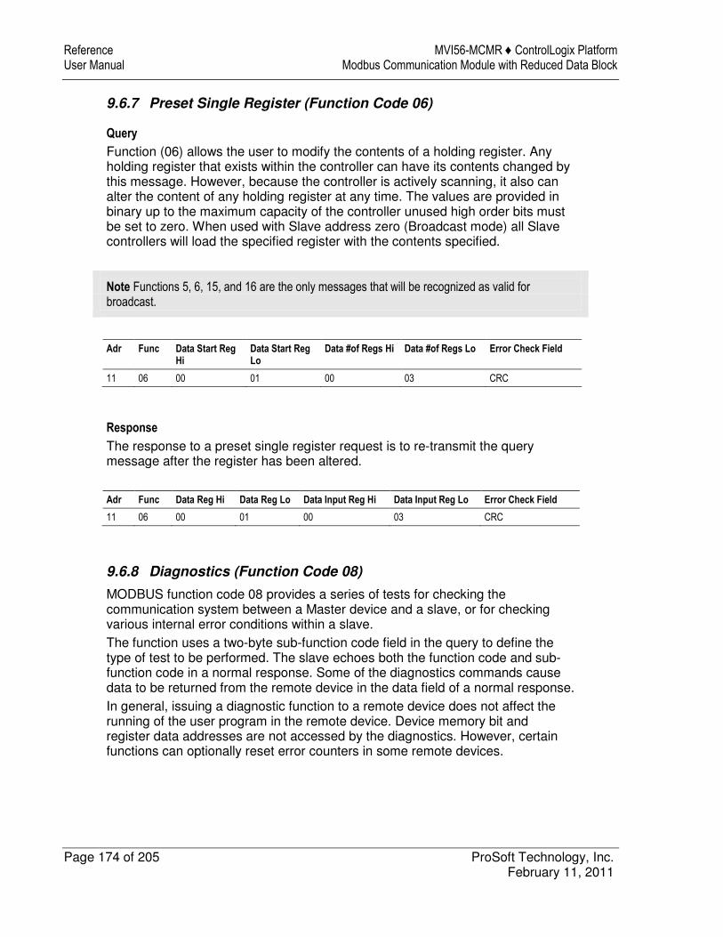
Reference MVI56-MCMR ♦ ControlLogix Platform User Manual Modbus Communication Module with Reduced Data Block
Page 174 of 205 ProSoft Technology, Inc. February 11, 2011
9.6.7 Preset Single Register (Function Code 06)
Query
Function (06) allows the user to modify the contents of a holding register. Any holding register that exists within the controller can have its contents changed by this message. However, because the controller is actively scanning, it also can alter the content of any holding register at any time. The values are provided in binary up to the maximum capacity of the controller unused high order bits must be set to zero. When used with Slave address zero (Broadcast mode) all Slave controllers will load the specified register with the contents specified.
Note Functions 5, 6, 15, and 16 are the only messages that will be recognized as valid for broadcast.
Adr Func Data Start Reg Hi
Data Start Reg Lo
Data #of Regs Hi Data #of Regs Lo Error Check Field
11 06 00 01 00 03 CRC
Response
The response to a preset single register request is to re-transmit the query message after the register has been altered.
Adr Func Data Reg Hi Data Reg Lo Data Input Reg Hi Data Input Reg Lo Error Check Field
11 06 00 01 00 03 CRC
9.6.8 Diagnostics (Function Code 08)
MODBUS function code 08 provides a series of tests for checking the communication system between a Master device and a slave, or for checking various internal error conditions within a slave. The function uses a two-byte sub-function code field in the query to define the type of test to be performed. The slave echoes both the function code and sub-function code in a normal response. Some of the diagnostics commands cause data to be returned from the remote device in the data field of a normal response. In general, issuing a diagnostic function to a remote device does not affect the running of the user program in the remote device. Device memory bit and register data addresses are not accessed by the diagnostics. However, certain functions can optionally reset error counters in some remote devices.
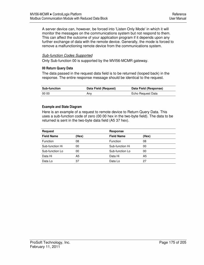
MVI56-MCMR ♦ ControlLogix Platform Reference Modbus Communication Module with Reduced Data Block User Manual
ProSoft Technology, Inc. Page 175 of 205 February 11, 2011
A server device can, however, be forced into 'Listen Only Mode' in which it will monitor the messages on the communications system but not respond to them. This can affect the outcome of your application program if it depends upon any further exchange of data with the remote device. Generally, the mode is forced to remove a malfunctioning remote device from the communications system.
Sub-function Codes Supported
Only Sub-function 00 is supported by the MVI56-MCMR gateway.
00 Return Query Data
The data passed in the request data field is to be returned (looped back) in the response. The entire response message should be identical to the request.
Sub-function Data Field (Request) Data Field (Response)
00 00 Any Echo Request Data
Example and State Diagram
Here is an example of a request to remote device to Return Query Data. This uses a sub-function code of zero (00 00 hex in the two-byte field). The data to be returned is sent in the two-byte data field (A5 37 hex).
Request Response
Field Name (Hex) Field Name (Hex)
Function 08 Function 08
Sub-function Hi 00 Sub-function Hi 00
Sub-function Lo 00 Sub-function Lo 00
Data Hi A5 Data Hi A5
Data Lo 37 Data Lo 27
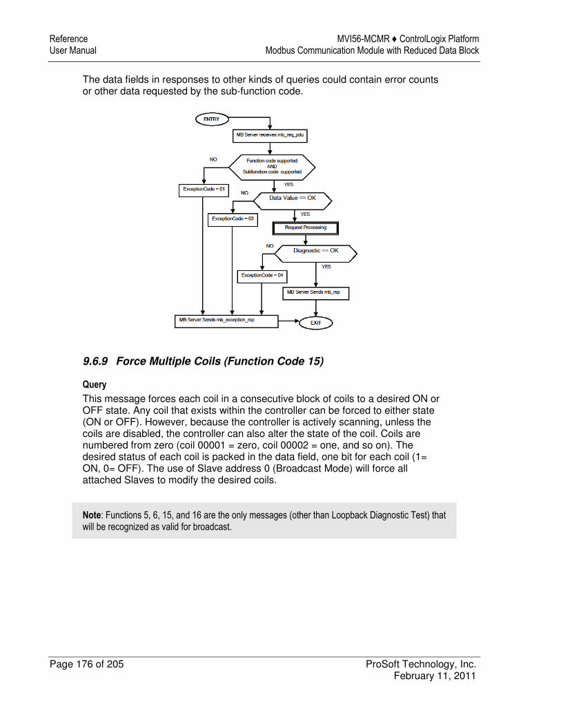
Reference MVI56-MCMR ♦ ControlLogix Platform User Manual Modbus Communication Module with Reduced Data Block
Page 176 of 205 ProSoft Technology, Inc. February 11, 2011
The data fields in responses to other kinds of queries could contain error counts or other data requested by the sub-function code.
9.6.9 Force Multiple Coils (Function Code 15)
Query
This message forces each coil in a consecutive block of coils to a desired ON or OFF state. Any coil that exists within the controller can be forced to either state (ON or OFF). However, because the controller is actively scanning, unless the coils are disabled, the controller can also alter the state of the coil. Coils are numbered from zero (coil 00001 = zero, coil 00002 = one, and so on). The desired status of each coil is packed in the data field, one bit for each coil (1= ON, 0= OFF). The use of Slave address 0 (Broadcast Mode) will force all attached Slaves to modify the desired coils.
Note: Functions 5, 6, 15, and 16 are the only messages (other than Loopback Diagnostic Test) that will be recognized as valid for broadcast.
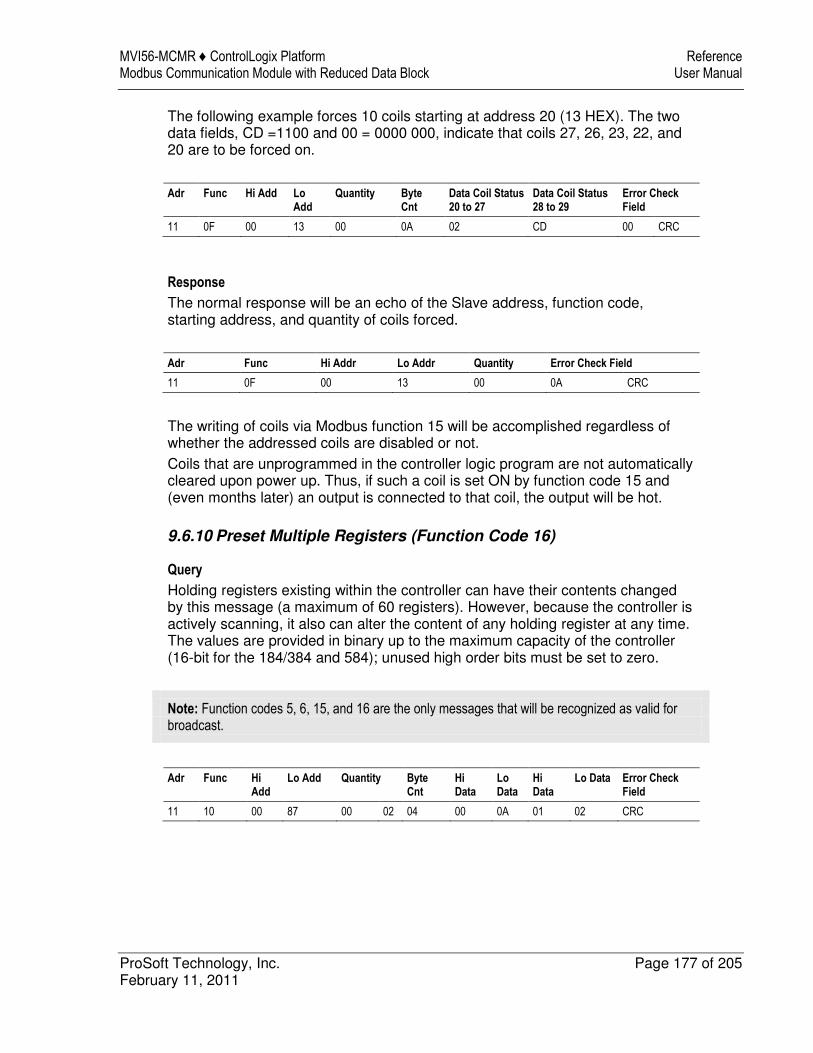
MVI56-MCMR ♦ ControlLogix Platform Reference Modbus Communication Module with Reduced Data Block User Manual
ProSoft Technology, Inc. Page 177 of 205 February 11, 2011
The following example forces 10 coils starting at address 20 (13 HEX). The two data fields, CD =1100 and 00 = 0000 000, indicate that coils 27, 26, 23, 22, and 20 are to be forced on.
Adr Func Hi Add Lo Add
Quantity Byte Cnt
Data Coil Status 20 to 27
Data Coil Status 28 to 29
Error Check Field
11 0F 00 13 00 0A 02 CD 00 CRC
Response
The normal response will be an echo of the Slave address, function code, starting address, and quantity of coils forced.
Adr Func Hi Addr Lo Addr Quantity Error Check Field
11 0F 00 13 00 0A CRC
The writing of coils via Modbus function 15 will be accomplished regardless of whether the addressed coils are disabled or not. Coils that are unprogrammed in the controller logic program are not automatically cleared upon power up. Thus, if such a coil is set ON by function code 15 and (even months later) an output is connected to that coil, the output will be hot.
9.6.10 Preset Multiple Registers (Function Code 16)
Query
Holding registers existing within the controller can have their contents changed by this message (a maximum of 60 registers). However, because the controller is actively scanning, it also can alter the content of any holding register at any time. The values are provided in binary up to the maximum capacity of the controller (16-bit for the 184/384 and 584); unused high order bits must be set to zero.
Note: Function codes 5, 6, 15, and 16 are the only messages that will be recognized as valid for broadcast.
Adr Func Hi Add
Lo Add Quantity Byte Cnt
Hi Data
Lo Data
Hi Data
Lo Data Error Check Field
11 10 00 87 00 02 04 00 0A 01 02 CRC
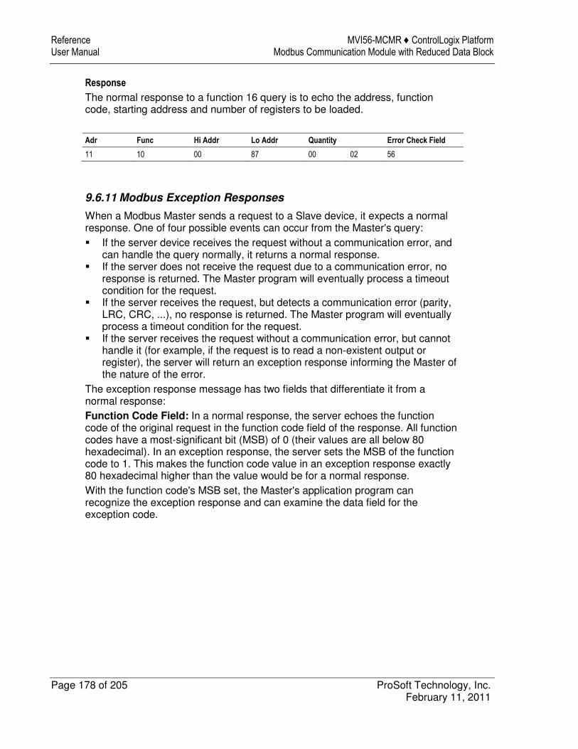
Reference MVI56-MCMR ♦ ControlLogix Platform User Manual Modbus Communication Module with Reduced Data Block
Page 178 of 205 ProSoft Technology, Inc. February 11, 2011
Response
The normal response to a function 16 query is to echo the address, function code, starting address and number of registers to be loaded.
Adr Func Hi Addr Lo Addr Quantity Error Check Field
11 10 00 87 00 02 56
9.6.11 Modbus Exception Responses
When a Modbus Master sends a request to a Slave device, it expects a normal response. One of four possible events can occur from the Master's query: � If the server device receives the request without a communication error, and
can handle the query normally, it returns a normal response. � If the server does not receive the request due to a communication error, no
response is returned. The Master program will eventually process a timeout condition for the request.
� If the server receives the request, but detects a communication error (parity, LRC, CRC, ...), no response is returned. The Master program will eventually process a timeout condition for the request.
� If the server receives the request without a communication error, but cannot handle it (for example, if the request is to read a non-existent output or register), the server will return an exception response informing the Master of the nature of the error.
The exception response message has two fields that differentiate it from a normal response: Function Code Field: In a normal response, the server echoes the function code of the original request in the function code field of the response. All function codes have a most-significant bit (MSB) of 0 (their values are all below 80 hexadecimal). In an exception response, the server sets the MSB of the function code to 1. This makes the function code value in an exception response exactly 80 hexadecimal higher than the value would be for a normal response. With the function code's MSB set, the Master's application program can recognize the exception response and can examine the data field for the exception code.
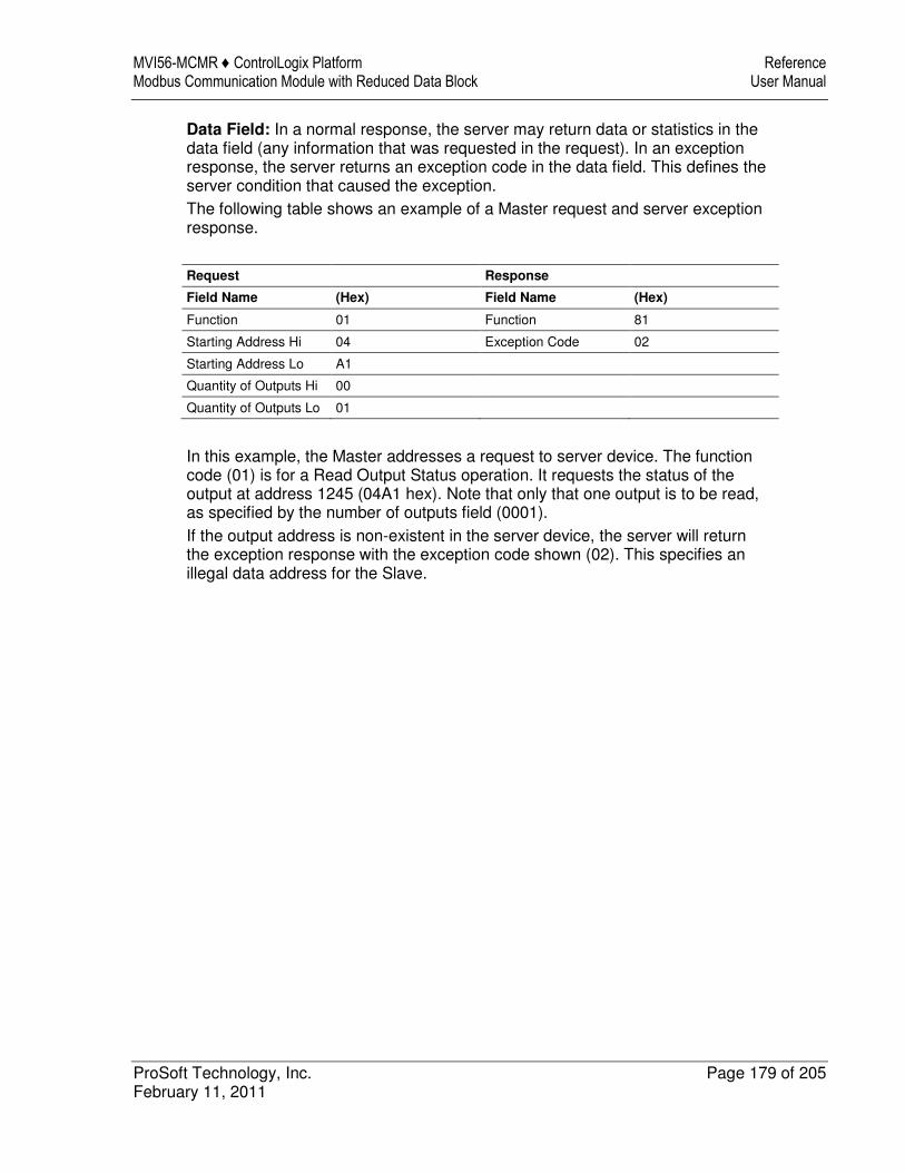
MVI56-MCMR ♦ ControlLogix Platform Reference Modbus Communication Module with Reduced Data Block User Manual
ProSoft Technology, Inc. Page 179 of 205 February 11, 2011
Data Field: In a normal response, the server may return data or statistics in the data field (any information that was requested in the request). In an exception response, the server returns an exception code in the data field. This defines the server condition that caused the exception. The following table shows an example of a Master request and server exception response.
Request Response
Field Name (Hex) Field Name (Hex)
Function 01 Function 81
Starting Address Hi 04 Exception Code 02
Starting Address Lo A1
Quantity of Outputs Hi 00
Quantity of Outputs Lo 01
In this example, the Master addresses a request to server device. The function code (01) is for a Read Output Status operation. It requests the status of the output at address 1245 (04A1 hex). Note that only that one output is to be read, as specified by the number of outputs field (0001). If the output address is non-existent in the server device, the server will return the exception response with the exception code shown (02). This specifies an illegal data address for the Slave.
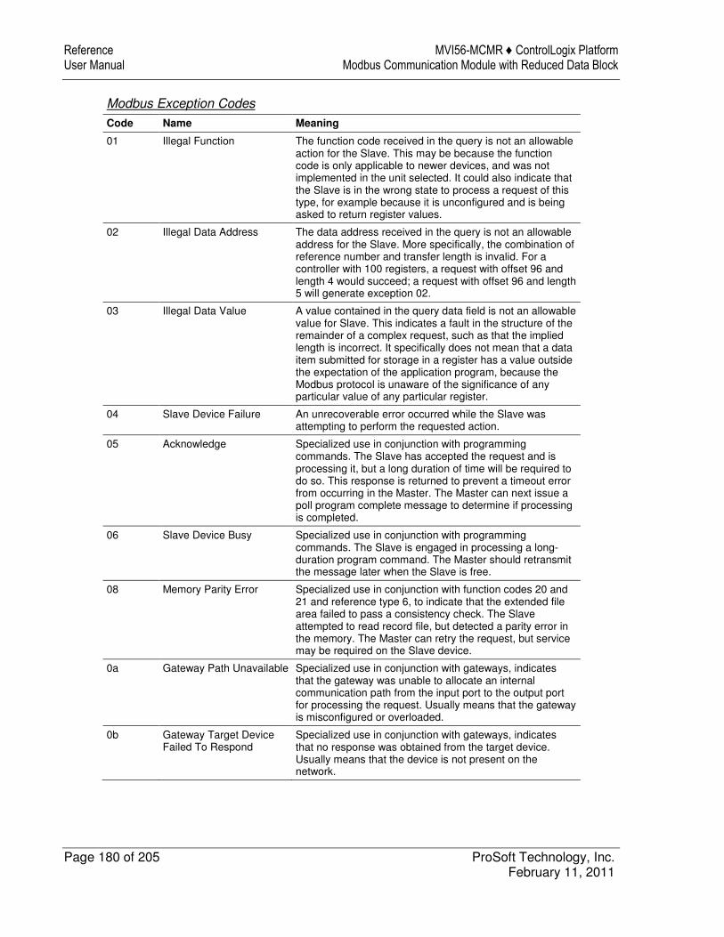
Reference MVI56-MCMR ♦ ControlLogix Platform User Manual Modbus Communication Module with Reduced Data Block
Page 180 of 205 ProSoft Technology, Inc. February 11, 2011
Modbus Exception Codes
Code Name Meaning
01 Illegal Function The function code received in the query is not an allowable action for the Slave. This may be because the function code is only applicable to newer devices, and was not implemented in the unit selected. It could also indicate that the Slave is in the wrong state to process a request of this type, for example because it is unconfigured and is being asked to return register values.
02 Illegal Data Address The data address received in the query is not an allowable address for the Slave. More specifically, the combination of reference number and transfer length is invalid. For a controller with 100 registers, a request with offset 96 and length 4 would succeed; a request with offset 96 and length 5 will generate exception 02.
03 Illegal Data Value A value contained in the query data field is not an allowable value for Slave. This indicates a fault in the structure of the remainder of a complex request, such as that the implied length is incorrect. It specifically does not mean that a data item submitted for storage in a register has a value outside the expectation of the application program, because the Modbus protocol is unaware of the significance of any particular value of any particular register.
04 Slave Device Failure An unrecoverable error occurred while the Slave was attempting to perform the requested action.
05 Acknowledge Specialized use in conjunction with programming commands. The Slave has accepted the request and is processing it, but a long duration of time will be required to do so. This response is returned to prevent a timeout error from occurring in the Master. The Master can next issue a poll program complete message to determine if processing is completed.
06 Slave Device Busy Specialized use in conjunction with programming commands. The Slave is engaged in processing a long-duration program command. The Master should retransmit the message later when the Slave is free.
08 Memory Parity Error Specialized use in conjunction with function codes 20 and 21 and reference type 6, to indicate that the extended file area failed to pass a consistency check. The Slave attempted to read record file, but detected a parity error in the memory. The Master can retry the request, but service may be required on the Slave device.
0a Gateway Path Unavailable Specialized use in conjunction with gateways, indicates that the gateway was unable to allocate an internal communication path from the input port to the output port for processing the request. Usually means that the gateway is misconfigured or overloaded.
0b Gateway Target Device Failed To Respond
Specialized use in conjunction with gateways, indicates that no response was obtained from the target device. Usually means that the device is not present on the network.
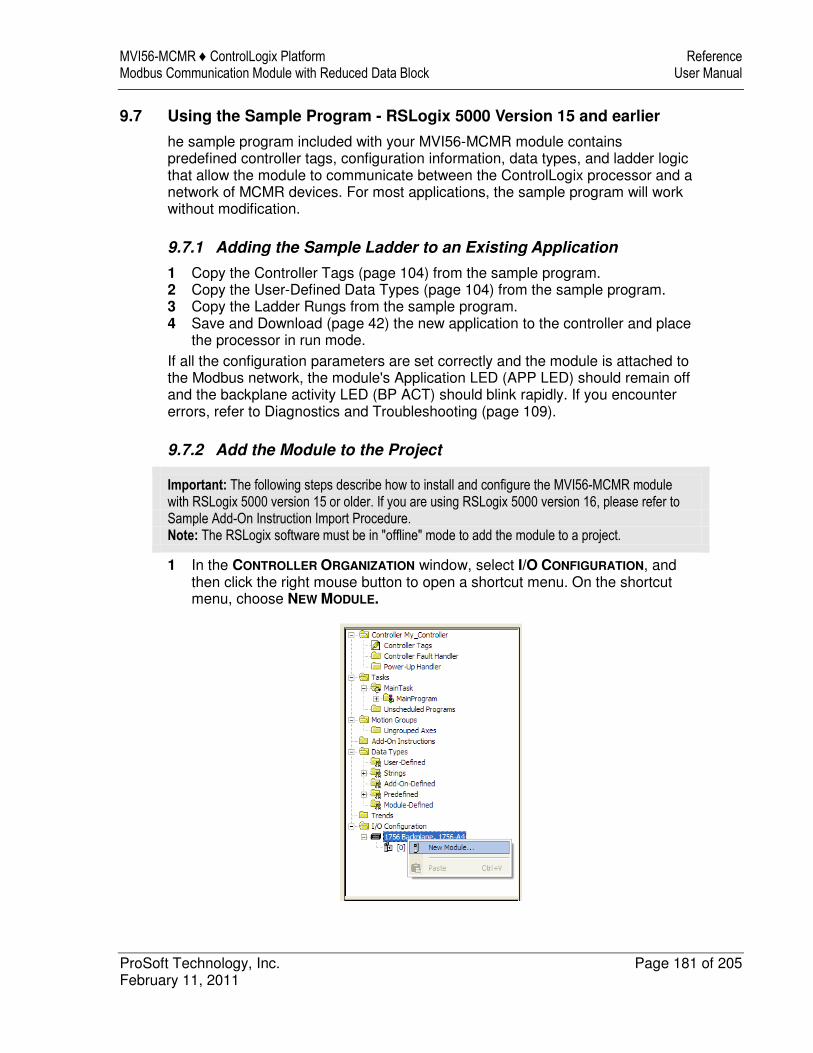
MVI56-MCMR ♦ ControlLogix Platform Reference Modbus Communication Module with Reduced Data Block User Manual
ProSoft Technology, Inc. Page 181 of 205 February 11, 2011
9.7 Using the Sample Program - RSLogix 5000 Version 15 and earlier
he sample program included with your MVI56-MCMR module contains predefined controller tags, configuration information, data types, and ladder logic that allow the module to communicate between the ControlLogix processor and a network of MCMR devices. For most applications, the sample program will work without modification.
9.7.1 Adding the Sample Ladder to an Existing Application
1 Copy the Controller Tags (page 104) from the sample program. 2 Copy the User-Defined Data Types (page 104) from the sample program. 3 Copy the Ladder Rungs from the sample program. 4 Save and Download (page 42) the new application to the controller and place
the processor in run mode. If all the configuration parameters are set correctly and the module is attached to the Modbus network, the module's Application LED (APP LED) should remain off and the backplane activity LED (BP ACT) should blink rapidly. If you encounter errors, refer to Diagnostics and Troubleshooting (page 109).
9.7.2 Add the Module to the Project
Important: The following steps describe how to install and configure the MVI56-MCMR module with RSLogix 5000 version 15 or older. If you are using RSLogix 5000 version 16, please refer to Sample Add-On Instruction Import Procedure. Note: The RSLogix software must be in "offline" mode to add the module to a project.
1 In the CONTROLLER ORGANIZATION window, select I/O CONFIGURATION, and then click the right mouse button to open a shortcut menu. On the shortcut menu, choose NEW MODULE.
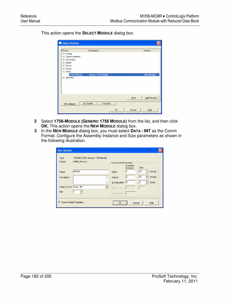
Reference MVI56-MCMR ♦ ControlLogix Platform User Manual Modbus Communication Module with Reduced Data Block
Page 182 of 205 ProSoft Technology, Inc. February 11, 2011
This action opens the SELECT MODULE dialog box.
2 Select 1756-MODULE (GENERIC 1756 MODULE) from the list, and then click OK. This action opens the NEW MODULE dialog box.
3 In the NEW MODULE dialog box, you must select DATA - INT as the Comm Format. Configure the Assembly Instance and Size parameters as shown in the following illustration.
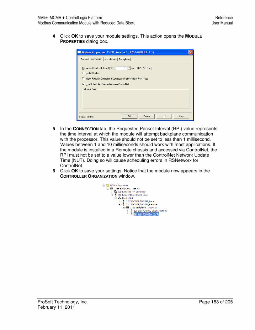
MVI56-MCMR ♦ ControlLogix Platform Reference Modbus Communication Module with Reduced Data Block User Manual
ProSoft Technology, Inc. Page 183 of 205 February 11, 2011
4 Click OK to save your module settings. This action opens the MODULE
PROPERTIES dialog box.
5 In the CONNECTION tab, the Requested Packet Interval (RPI) value represents the time interval at which the module will attempt backplane communication with the processor. This value should not be set to less than 1 millisecond. Values between 1 and 10 milliseconds should work with most applications. If the module is installed in a Remote chassis and accessed via ControlNet, the RPI must not be set to a value lower than the ControlNet Network Update Time (NUT). Doing so will cause scheduling errors in RSNetworx for ControlNet.
6 Click OK to save your settings. Notice that the module now appears in the CONTROLLER ORGANIZATION window.
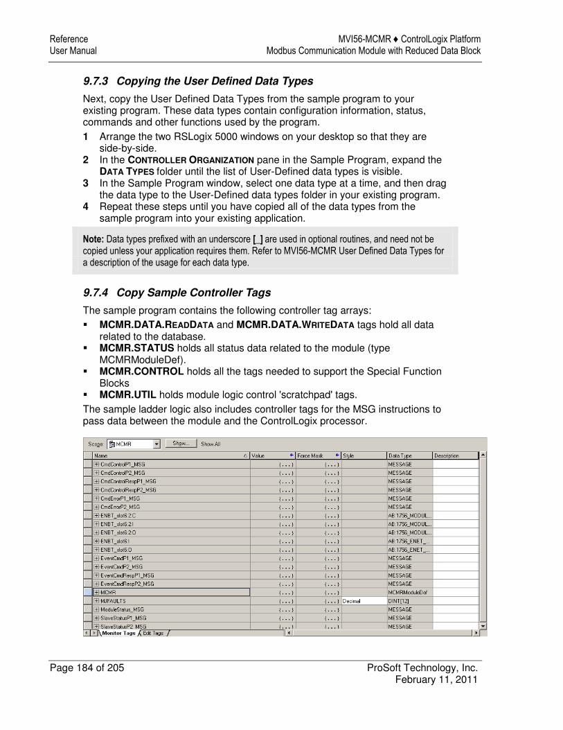
Reference MVI56-MCMR ♦ ControlLogix Platform User Manual Modbus Communication Module with Reduced Data Block
Page 184 of 205 ProSoft Technology, Inc. February 11, 2011
9.7.3 Copying the User Defined Data Types
Next, copy the User Defined Data Types from the sample program to your existing program. These data types contain configuration information, status, commands and other functions used by the program. 1 Arrange the two RSLogix 5000 windows on your desktop so that they are
side-by-side. 2 In the CONTROLLER ORGANIZATION pane in the Sample Program, expand the
DATA TYPES folder until the list of User-Defined data types is visible. 3 In the Sample Program window, select one data type at a time, and then drag
the data type to the User-Defined data types folder in your existing program. 4 Repeat these steps until you have copied all of the data types from the
sample program into your existing application.
Note: Data types prefixed with an underscore [_] are used in optional routines, and need not be copied unless your application requires them. Refer to MVI56-MCMR User Defined Data Types for a description of the usage for each data type.
9.7.4 Copy Sample Controller Tags
The sample program contains the following controller tag arrays: � MCMR.DATA.READDATA and MCMR.DATA.WRITEDATA tags hold all data
related to the database. � MCMR.STATUS holds all status data related to the module (type
MCMRModuleDef). � MCMR.CONTROL holds all the tags needed to support the Special Function
Blocks � MCMR.UTIL holds module logic control 'scratchpad' tags. The sample ladder logic also includes controller tags for the MSG instructions to pass data between the module and the ControlLogix processor.
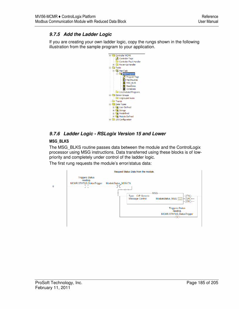
MVI56-MCMR ♦ ControlLogix Platform Reference Modbus Communication Module with Reduced Data Block User Manual
ProSoft Technology, Inc. Page 185 of 205 February 11, 2011
9.7.5 Add the Ladder Logic
If you are creating your own ladder logic, copy the rungs shown in the following illustration from the sample program to your application.
9.7.6 Ladder Logic - RSLogix Version 15 and Lower
MSG_BLKS
The MSG_BLKS routine passes data between the module and the ControlLogix processor using MSG instructions. Data transferred using these blocks is of low-priority and completely under control of the ladder logic. The first rung requests the module’s error/status data:
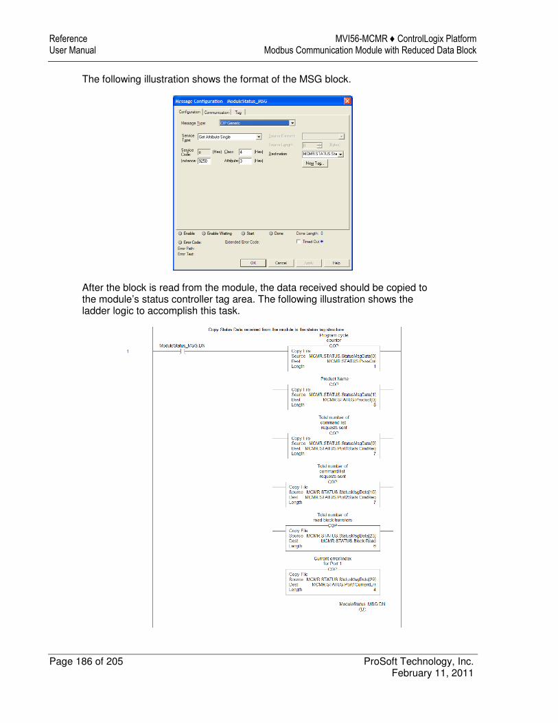
Reference MVI56-MCMR ♦ ControlLogix Platform User Manual Modbus Communication Module with Reduced Data Block
Page 186 of 205 ProSoft Technology, Inc. February 11, 2011
The following illustration shows the format of the MSG block.
After the block is read from the module, the data received should be copied to the module’s status controller tag area. The following illustration shows the ladder logic to accomplish this task.
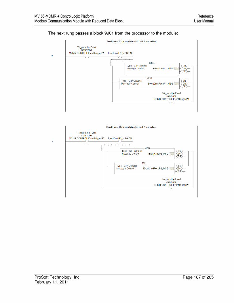
MVI56-MCMR ♦ ControlLogix Platform Reference Modbus Communication Module with Reduced Data Block User Manual
ProSoft Technology, Inc. Page 187 of 205 February 11, 2011
The next rung passes a block 9901 from the processor to the module:
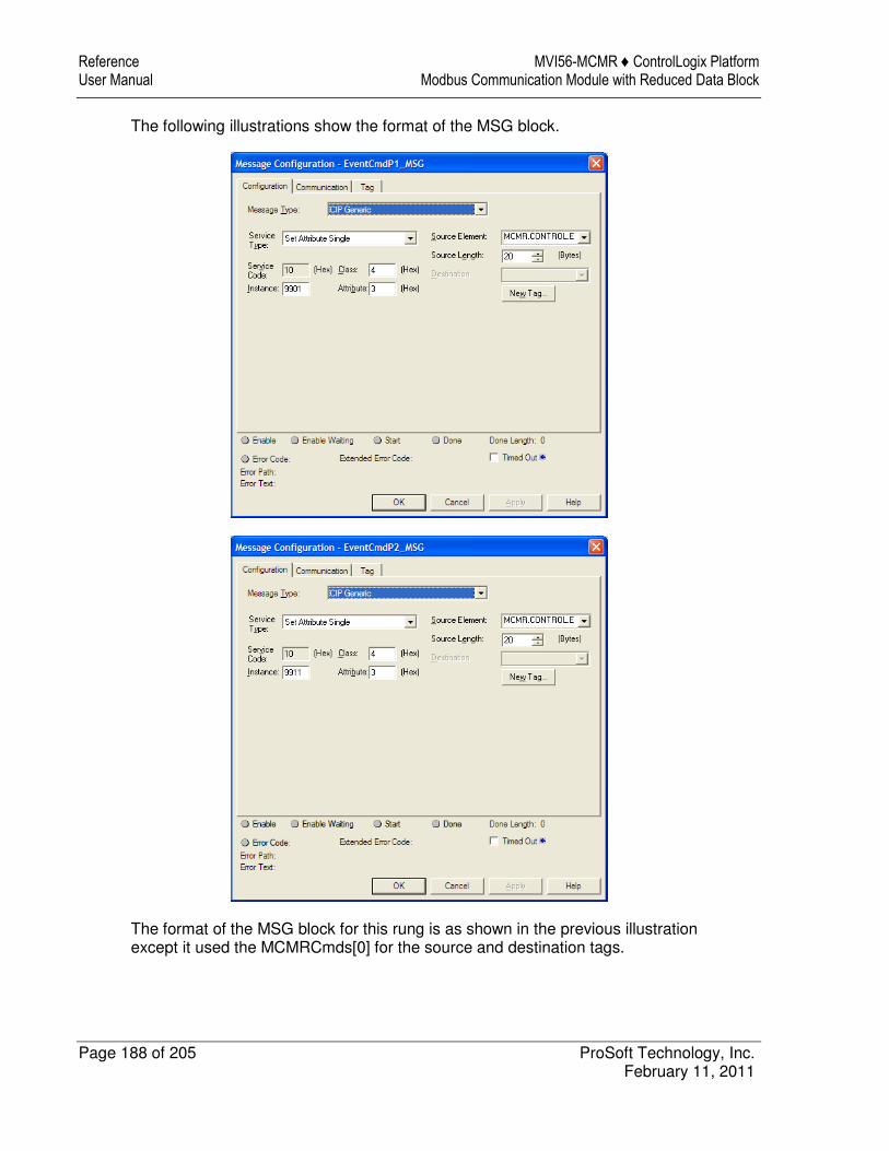
Reference MVI56-MCMR ♦ ControlLogix Platform User Manual Modbus Communication Module with Reduced Data Block
Page 188 of 205 ProSoft Technology, Inc. February 11, 2011
The following illustrations show the format of the MSG block.
The format of the MSG block for this rung is as shown in the previous illustration except it used the MCMRCmds[0] for the source and destination tags.
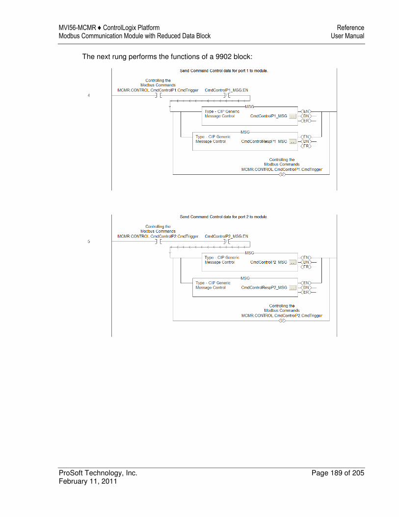
MVI56-MCMR ♦ ControlLogix Platform Reference Modbus Communication Module with Reduced Data Block User Manual
ProSoft Technology, Inc. Page 189 of 205 February 11, 2011
The next rung performs the functions of a 9902 block:

Reference MVI56-MCMR ♦ ControlLogix Platform User Manual Modbus Communication Module with Reduced Data Block
Page 190 of 205 ProSoft Technology, Inc. February 11, 2011
The following illustrations show the format of the MSG block.
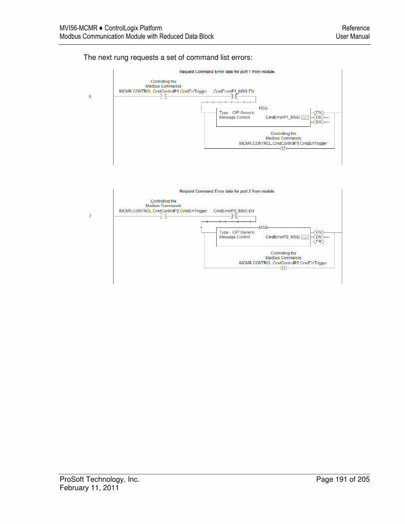
MVI56-MCMR ♦ ControlLogix Platform Reference Modbus Communication Module with Reduced Data Block User Manual
ProSoft Technology, Inc. Page 191 of 205 February 11, 2011
The next rung requests a set of command list errors:

Reference MVI56-MCMR ♦ ControlLogix Platform User Manual Modbus Communication Module with Reduced Data Block
Page 192 of 205 ProSoft Technology, Inc. February 11, 2011
The following illustration shows the format of the MSG block.
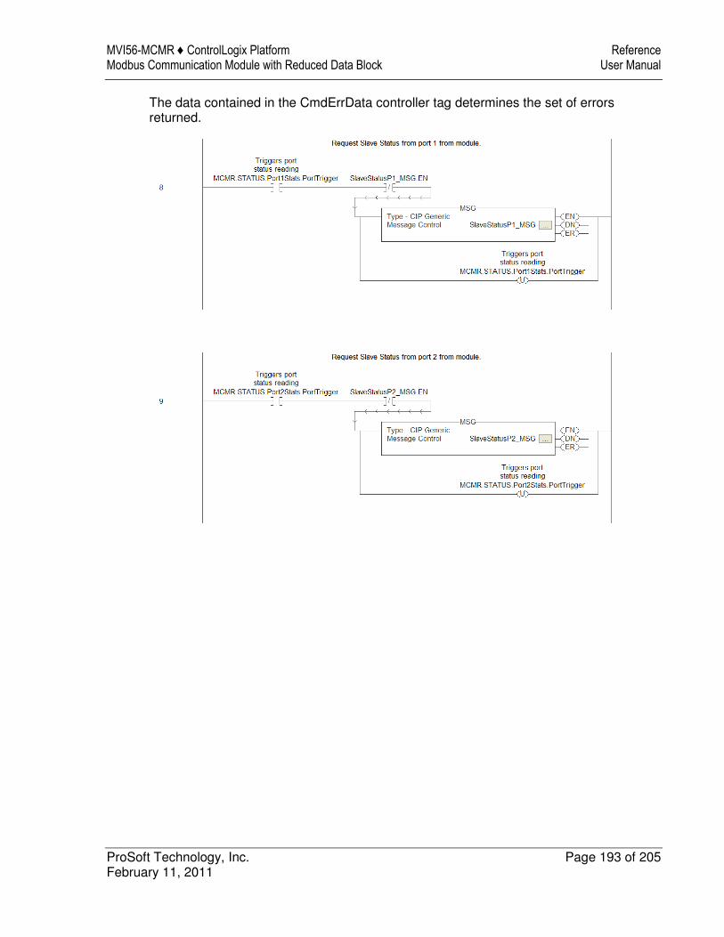
MVI56-MCMR ♦ ControlLogix Platform Reference Modbus Communication Module with Reduced Data Block User Manual
ProSoft Technology, Inc. Page 193 of 205 February 11, 2011
The data contained in the CmdErrData controller tag determines the set of errors returned.
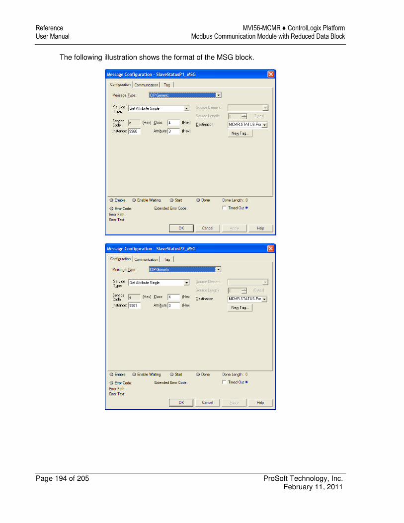
Reference MVI56-MCMR ♦ ControlLogix Platform User Manual Modbus Communication Module with Reduced Data Block
Page 194 of 205 ProSoft Technology, Inc. February 11, 2011
The following illustration shows the format of the MSG block.
MVI56-MCMR ♦ ControlLogix Platform Support, Service & Warranty Modbus Communication Module with Reduced Data Block User Manual
ProSoft Technology, Inc. Page 195 of 205 February 11, 2011
10 Support, Service & Warranty
In This Chapter
� Contacting Technical Support ............................................................. 195
� Return Material Authorization (RMA) Policies and Conditions ............. 197
� LIMITED WARRANTY ......................................................................... 199
Contacting Technical Support
ProSoft Technology, Inc. (ProSoft) is committed to providing the most efficient and effective support possible. Before calling, please gather the following information to assist in expediting this process: 1 Product Version Number 2 System architecture 3 Network details If the issue is hardware related, we will also need information regarding: 1 Module configuration and associated ladder files, if any 2 Module operation and any unusual behavior 3 Configuration/Debug status information 4 LED patterns 5 Details about the serial, Ethernet or fieldbus devices interfaced to the module,
if any.
Note: For technical support calls within the United States, an after-hours answering system allows 24-hour/7-days-a-week pager access to one of our qualified Technical and/or Application Support Engineers. Detailed contact information for all our worldwide locations is available on the following page.

Support, Service & Warranty MVI56-MCMR ♦ ControlLogix Platform User Manual Modbus Communication Module with Reduced Data Block
Page 196 of 205 ProSoft Technology, Inc. February 11, 2011
Internet Web Site: www.prosoft-technology.com/support E-mail address: [email protected]
Asia Pacific (location in Malaysia)
Tel: +603.7724.2080, E-mail: [email protected] Languages spoken include: Chinese, English
Asia Pacific (location in China)
Tel: +86.21.5187.7337 x888, E-mail: [email protected] Languages spoken include: Chinese, English
Europe (location in Toulouse, France)
Tel: +33 (0) 5.34.36.87.20, E-mail: [email protected] Languages spoken include: French, English
Europe (location in Dubai, UAE)
Tel: +971-4-214-6911, E-mail: [email protected] Languages spoken include: English, Hindi
North America (location in California)
Tel: +1.661.716.5100, E-mail: [email protected] Languages spoken include: English, Spanish
Latin America (Oficina Regional)
Tel: +1-281-2989109, E-Mail: [email protected] Languages spoken include: Spanish, English
Latin America (location in Puebla, Mexico)
Tel: +52-222-3-99-6565, E-mail: [email protected] Languages spoken include: Spanish
Brasil (location in Sao Paulo)
Tel: +55-11-5083-3776, E-mail: [email protected] Languages spoken include: Portuguese, English

MVI56-MCMR ♦ ControlLogix Platform Support, Service & Warranty Modbus Communication Module with Reduced Data Block User Manual
ProSoft Technology, Inc. Page 197 of 205 February 11, 2011
10.1 Return Material Authorization (RMA) Policies and Conditions
The following Return Material Authorization (RMA) Policies and Conditions (collectively, "RMA Policies") apply to any returned product. These RMA Policies are subject to change by ProSoft Technology, Inc., without notice. For warranty information, see Limited Warranty (page 199). In the event of any inconsistency between the RMA Policies and the Warranty, the Warranty shall govern.
10.1.1 Returning Any Product
a) In order to return a Product for repair, exchange, or otherwise, the Customer must obtain a Return Material Authorization (RMA) number from ProSoft Technology and comply with ProSoft Technology shipping instructions.
b) In the event that the Customer experiences a problem with the Product for any reason, Customer should contact ProSoft Technical Support at one of the telephone numbers listed above (page 195). A Technical Support Engineer will request that you perform several tests in an attempt to isolate the problem. If after completing these tests, the Product is found to be the source of the problem, we will issue an RMA.
c) All returned Products must be shipped freight prepaid, in the original shipping container or equivalent, to the location specified by ProSoft Technology, and be accompanied by proof of purchase and receipt date. The RMA number is to be prominently marked on the outside of the shipping box. Customer agrees to insure the Product or assume the risk of loss or damage in transit. Products shipped to ProSoft Technology using a shipment method other than that specified by ProSoft Technology, or shipped without an RMA number will be returned to the Customer, freight collect. Contact ProSoft Technical Support for further information.
d) A 10% restocking fee applies to all warranty credit returns, whereby a Customer has an application change, ordered too many, does not need, etc. Returns for credit require that all accessory parts included in the original box (i.e.; antennas, cables) be returned. Failure to return these items will result in a deduction from the total credit due for each missing item.

Support, Service & Warranty MVI56-MCMR ♦ ControlLogix Platform User Manual Modbus Communication Module with Reduced Data Block
Page 198 of 205 ProSoft Technology, Inc. February 11, 2011
10.1.2 Returning Units Under Warranty
A Technical Support Engineer must approve the return of Product under ProSoft Technology’s Warranty:
a) A replacement module will be shipped and invoiced. A purchase order will be required.
b) Credit for a product under warranty will be issued upon receipt of authorized product by ProSoft Technology at designated location referenced on the Return Material Authorization i. If a defect is found and is determined to be customer generated, or if
the defect is otherwise not covered by ProSoft Technology s warranty, there will be no credit given. Customer will be contacted and can request module be returned at their expense;
ii. If defect is customer generated and is repairable, customer can authorize ProSoft Technology to repair the unit by providing a purchase order for 30% of the current list price plus freight charges, duties and taxes as applicable.
10.1.3 Returning Units Out of Warranty
a) Customer sends unit in for evaluation to location specified by ProSoft Technology, freight prepaid.
b) If no defect is found, Customer will be charged the equivalent of $100 USD, plus freight charges, duties and taxes as applicable. A new purchase order will be required.
c) If unit is repaired, charge to Customer will be 30% of current list price (USD) plus freight charges, duties and taxes as applicable. A new purchase order will be required or authorization to use the purchase order submitted for evaluation fee.
The following is a list of non-repairable units: o 3150 - All o 3750 o 3600 - All o 3700 o 3170 - All o 3250 o 1560 - Can be repaired, only if defect is the power supply o 1550 - Can be repaired, only if defect is the power supply o 3350 o 3300 o 1500 - All

MVI56-MCMR ♦ ControlLogix Platform Support, Service & Warranty Modbus Communication Module with Reduced Data Block User Manual
ProSoft Technology, Inc. Page 199 of 205 February 11, 2011
10.2 LIMITED WARRANTY
This Limited Warranty ("Warranty") governs all sales of hardware, software, and other products (collectively, "Product") manufactured and/or offered for sale by ProSoft Technology, Incorporated (ProSoft), and all related services provided by ProSoft, including maintenance, repair, warranty exchange, and service programs (collectively, "Services"). By purchasing or using the Product or Services, the individual or entity purchasing or using the Product or Services ("Customer") agrees to all of the terms and provisions (collectively, the "Terms") of this Limited Warranty. All sales of software or other intellectual property are, in addition, subject to any license agreement accompanying such software or other intellectual property.
10.2.1 What Is Covered By This Warranty
a) Warranty On New Products: ProSoft warrants, to the original purchaser, that the Product that is the subject of the sale will (1) conform to and perform in accordance with published specifications prepared, approved and issued by ProSoft, and (2) will be free from defects in material or workmanship; provided these warranties only cover Product that is sold as new. This Warranty expires three (3) years from the date of shipment for Product purchased on or after January 1st, 2008, or one (1) year from the date of shipment for Product purchased before January 1st, 2008 (the "Warranty Period"). If the Customer discovers within the Warranty Period a failure of the Product to conform to specifications, or a defect in material or workmanship of the Product, the Customer must promptly notify ProSoft by fax, email or telephone. In no event may that notification be received by ProSoft later than 39 months from date of original shipment. Within a reasonable time after notification, ProSoft will correct any failure of the Product to conform to specifications or any defect in material or workmanship of the Product, with either new or remanufactured replacement parts. ProSoft reserves the right, and at its sole discretion, may replace unrepairable units with new or remanufactured equipment. All replacement units will be covered under warranty for the 3 year period commencing from the date of original equipment purchase, not the date of shipment of the replacement unit. Such repair, including both parts and labor, will be performed at ProSoft’s expense. All warranty service will be performed at service centers designated by ProSoft.
b) Warranty On Services: Materials and labor performed by ProSoft to repair a verified malfunction or defect are warranteed in the terms specified above for new Product, provided said warranty will be for the period remaining on the original new equipment warranty or, if the original warranty is no longer in effect, for a period of 90 days from the date of repair.
Support, Service & Warranty MVI56-MCMR ♦ ControlLogix Platform User Manual Modbus Communication Module with Reduced Data Block
Page 200 of 205 ProSoft Technology, Inc. February 11, 2011
10.2.2 What Is Not Covered By This Warranty
a) ProSoft makes no representation or warranty, expressed or implied, that the operation of software purchased from ProSoft will be uninterrupted or error free or that the functions contained in the software will meet or satisfy the purchaser’s intended use or requirements; the Customer assumes complete responsibility for decisions made or actions taken based on information obtained using ProSoft software.
b) This Warranty does not cover the failure of the Product to perform specified functions, or any other non-conformance, defects, losses or damages caused by or attributable to any of the following: (i) shipping; (ii) improper installation or other failure of Customer to adhere to ProSoft’s specifications or instructions; (iii) unauthorized repair or maintenance; (iv) attachments, equipment, options, parts, software, or user-created programming (including, but not limited to, programs developed with any IEC 61131-3, "C" or any variant of "C" programming languages) not furnished by ProSoft; (v) use of the Product for purposes other than those for which it was designed; (vi) any other abuse, misapplication, neglect or misuse by the Customer; (vii) accident, improper testing or causes external to the Product such as, but not limited to, exposure to extremes of temperature or humidity, power failure or power surges; or (viii) disasters such as fire, flood, earthquake, wind and lightning.
c) The information in this Agreement is subject to change without notice. ProSoft shall not be liable for technical or editorial errors or omissions made herein; nor for incidental or consequential damages resulting from the furnishing, performance or use of this material. The user guide included with your original product purchase from ProSoft contains information protected by copyright. No part of the guide may be duplicated or reproduced in any form without prior written consent from ProSoft.
10.2.3 Disclaimer Regarding High Risk Activities
Product manufactured or supplied by ProSoft is not fault tolerant and is not designed, manufactured or intended for use in hazardous environments requiring fail-safe performance including and without limitation: the operation of nuclear facilities, aircraft navigation of communication systems, air traffic control, direct life support machines or weapons systems in which the failure of the product could lead directly or indirectly to death, personal injury or severe physical or environmental damage (collectively, "high risk activities"). ProSoft specifically disclaims any express or implied warranty of fitness for high risk activities.
MVI56-MCMR ♦ ControlLogix Platform Support, Service & Warranty Modbus Communication Module with Reduced Data Block User Manual
ProSoft Technology, Inc. Page 201 of 205 February 11, 2011
10.2.4 Intellectual Property Indemnity
Buyer shall indemnify and hold harmless ProSoft and its employees from and against all liabilities, losses, claims, costs and expenses (including attorney’s fees and expenses) related to any claim, investigation, litigation or proceeding (whether or not ProSoft is a party) which arises or is alleged to arise from Buyer’s acts or omissions under these Terms or in any way with respect to the Products. Without limiting the foregoing, Buyer (at its own expense) shall indemnify and hold harmless ProSoft and defend or settle any action brought against such Companies to the extent based on a claim that any Product made to Buyer specifications infringed intellectual property rights of another party. ProSoft makes no warranty that the product is or will be delivered free of any person’s claiming of patent, trademark, or similar infringement. The Buyer assumes all risks (including the risk of suit) that the product or any use of the product will infringe existing or subsequently issued patents, trademarks, or copyrights.
a) Any documentation included with Product purchased from ProSoft is protected by copyright and may not be duplicated or reproduced in any form without prior written consent from ProSoft.
b) ProSoft’s technical specifications and documentation that are included with the Product are subject to editing and modification without notice.
c) Transfer of title shall not operate to convey to Customer any right to make, or have made, any Product supplied by ProSoft.
d) Customer is granted no right or license to use any software or other intellectual property in any manner or for any purpose not expressly permitted by any license agreement accompanying such software or other intellectual property.
e) Customer agrees that it shall not, and shall not authorize others to, copy software provided by ProSoft (except as expressly permitted in any license agreement accompanying such software); transfer software to a third party separately from the Product; modify, alter, translate, decode, decompile, disassemble, reverse-engineer or otherwise attempt to derive the source code of the software or create derivative works based on the software; export the software or underlying technology in contravention of applicable US and international export laws and regulations; or use the software other than as authorized in connection with use of Product.
f) Additional Restrictions Relating To Software And Other Intellectual Property In addition to compliance with the Terms of this Warranty, Customers purchasing software or other intellectual property shall comply with any license agreement accompanying such software or other intellectual property. Failure to do so may void this Warranty with respect to such software and/or other intellectual property.
10.2.5 Disclaimer of all Other Warranties
The Warranty set forth in What Is Covered By This Warranty (page 199) are in lieu of all other warranties, express or implied, including but not limited to the implied warranties of merchantability and fitness for a particular purpose.
Support, Service & Warranty MVI56-MCMR ♦ ControlLogix Platform User Manual Modbus Communication Module with Reduced Data Block
Page 202 of 205 ProSoft Technology, Inc. February 11, 2011
10.2.6 Limitation of Remedies **
In no event will ProSoft or its Dealer be liable for any special, incidental or consequential damages based on breach of warranty, breach of contract, negligence, strict tort or any other legal theory. Damages that ProSoft or its Dealer will not be responsible for include, but are not limited to: Loss of profits; loss of savings or revenue; loss of use of the product or any associated equipment; loss of data; cost of capital; cost of any substitute equipment, facilities, or services; downtime; the claims of third parties including, customers of the Purchaser; and, injury to property.
** Some areas do not allow time limitations on an implied warranty, or allow the exclusion or limitation of incidental or consequential damages. In such areas, the above limitations may not apply. This Warranty gives you specific legal rights, and you may also have other rights which vary from place to place.
10.2.7 Time Limit for Bringing Suit
Any action for breach of warranty must be commenced within 39 months following shipment of the Product.
10.2.8 No Other Warranties
Unless modified in writing and signed by both parties, this Warranty is understood to be the complete and exclusive agreement between the parties, suspending all oral or written prior agreements and all other communications between the parties relating to the subject matter of this Warranty, including statements made by salesperson. No employee of ProSoft or any other party is authorized to make any warranty in addition to those made in this Warranty. The Customer is warned, therefore, to check this Warranty carefully to see that it correctly reflects those terms that are important to the Customer.
10.2.9 Allocation of Risks
This Warranty allocates the risk of product failure between ProSoft and the Customer. This allocation is recognized by both parties and is reflected in the price of the goods. The Customer acknowledges that it has read this Warranty, understands it, and is bound by its Terms.
10.2.10 Controlling Law and Severability
This Warranty shall be governed by and construed in accordance with the laws of the United States and the domestic laws of the State of California, without reference to its conflicts of law provisions. If for any reason a court of competent jurisdiction finds any provisions of this Warranty, or a portion thereof, to be unenforceable, that provision shall be enforced to the maximum extent permissible and the remainder of this Warranty shall remain in full force and effect. Any cause of action with respect to the Product or Services must be instituted in a court of competent jurisdiction in the State of California.
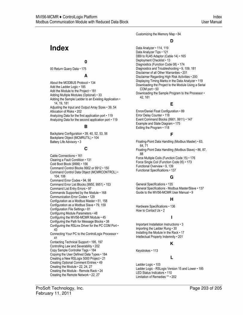
MVI56-MCMR ♦ ControlLogix Platform Index Modbus Communication Module with Reduced Data Block User Manual
ProSoft Technology, Inc. Page 203 of 205 February 11, 2011
Index
0
00 Return Query Data • 175
A
About the MODBUS Protocol • 134 Add the Ladder Logic • 185 Add the Module to the Project • 181 Adding Multiple Modules (Optional) • 33 Adding the Sample Ladder to an Existing Application •
14, 19, 181 Adjusting the Input and Output Array Sizes • 39, 54 Allocation of Risks • 202 Analyzing Data for the first application port • 119 Analyzing Data for the second application port • 119
B
Backplane Configuration • 39, 40, 52, 53, 56 Backplane Object (MCMRUTIL) • 104 Battery Life Advisory • 3
C
Cable Connections • 161 Clearing a Fault Condition • 131 Cold Boot Block (9999) • 156 Command Control Blocks 9902 or 9912 • 150 Command Control Data Object (MCMRCONTROL) •
104, 106 Command Error Codes • 94, 98 Command Error List Blocks (9950, 9951) • 153 Command List Entry Errors • 97 Commands Supported by the Module • 168 Communication Error Codes • 129 Configuration as a Modbus Master • 51, 158 Configuration as a Modbus Slave • 79, 159 Configuration File Settings • 81 Configuring Module Parameters • 48 Configuring the MVI56-MCMR Module • 45 Configuring the Path for Message Blocks • 38 Configuring the RSLinx Driver for the PC COM Port •
43 Connecting Your PC to the ControlLogix Processor •
41 Contacting Technical Support • 195, 197 Controlling Law and Severability • 202 Copy Sample Controller Tags • 184 Copying the User Defined Data Types • 184 Creating a New RSLogix 5000 Project • 21 Creating Optional Comment Entries • 49 Creating the Module • 22, 24, 27 Creating the Module - Remote Rack • 24 Creating the Remote Network • 22, 27
Customizing the Memory Map • 84
D
Data Analyzer • 114, 119 Data Analyzer Tips • 121 DB9 to RJ45 Adaptor (Cable 14) • 165 Deployment Checklist • 13 Diagnostics (Function Code 08) • 174 Diagnostics and Troubleshooting • 9, 109, 181 Disclaimer of all Other Warranties • 201 Disclaimer Regarding High Risk Activities • 200 Displaying Timing Marks in the Data Analyzer • 119 Downloading the Project to the Module Using a Serial
COM port • 50 Downloading the Sample Program to the Processor •
42, 181
E
Enron/Daniel Float Configuration • 89 Error Delay Counter • 118 Event Command Blocks (9901, 9911) • 147 Example and State Diagram • 175 Exiting the Program • 118
F
Floating-Point Data Handling (Modbus Master) • 63, 64, 71
Floating-Point Data Handling (Modbus Slave) • 86, 87, 88
Force Multiple Coils (Function Code 15) • 176 Force Single Coil (Function Code 05) • 173 Functional Overview • 9, 139 Functional Specifications • 137
G
General Specifications • 135 General Specifications - Modbus Master/Slave • 137 Guide to the MVI56-MCMR User Manual • 9
H
Hardware Specifications • 136 How to Contact Us • 2
I
Important Installation Instructions • 3 Importing the Ladder Rung • 30 Installing the Module in the Rack • 17 Intellectual Property Indemnity • 201
K
Keystrokes • 113
L
Ladder Logic • 103 Ladder Logic - RSLogix Version 15 and Lower • 185 LED Status Indicators • 110 Limitation of Remedies ** • 202
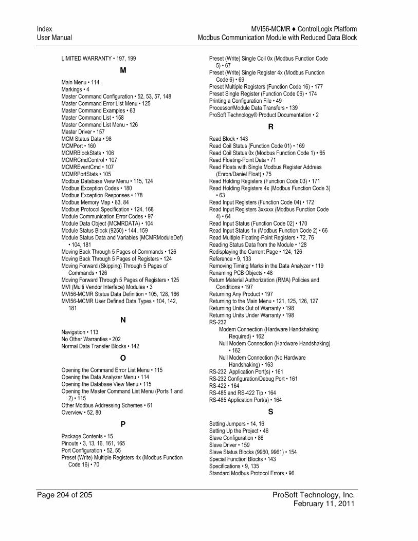
Index MVI56-MCMR ♦ ControlLogix Platform User Manual Modbus Communication Module with Reduced Data Block
Page 204 of 205 ProSoft Technology, Inc. February 11, 2011
LIMITED WARRANTY • 197, 199
M
Main Menu • 114 Markings • 4 Master Command Configuration • 52, 53, 57, 148 Master Command Error List Menu • 125 Master Command Examples • 63 Master Command List • 158 Master Command List Menu • 126 Master Driver • 157 MCM Status Data • 98 MCMPort • 160 MCMRBlockStats • 106 MCMRCmdControl • 107 MCMREventCmd • 107 MCMRPortStats • 105 Modbus Database View Menu • 115, 124 Modbus Exception Codes • 180 Modbus Exception Responses • 178 Modbus Memory Map • 83, 84 Modbus Protocol Specification • 124, 168 Module Communication Error Codes • 97 Module Data Object (MCMRDATA) • 104 Module Status Block (9250) • 144, 159 Module Status Data and Variables (MCMRModuleDef)
• 104, 181 Moving Back Through 5 Pages of Commands • 126 Moving Back Through 5 Pages of Registers • 124 Moving Forward (Skipping) Through 5 Pages of
Commands • 126 Moving Forward Through 5 Pages of Registers • 125 MVI (Multi Vendor Interface) Modules • 3 MVI56-MCMR Status Data Definition • 105, 128, 166 MVI56-MCMR User Defined Data Types • 104, 142,
181
N
Navigation • 113 No Other Warranties • 202 Normal Data Transfer Blocks • 142
O
Opening the Command Error List Menu • 115 Opening the Data Analyzer Menu • 114 Opening the Database View Menu • 115 Opening the Master Command List Menu (Ports 1 and
2) • 115 Other Modbus Addressing Schemes • 61 Overview • 52, 80
P
Package Contents • 15 Pinouts • 3, 13, 16, 161, 165 Port Configuration • 52, 55 Preset (Write) Multiple Registers 4x (Modbus Function
Code 16) • 70
Preset (Write) Single Coil 0x (Modbus Function Code 5) • 67
Preset (Write) Single Register 4x (Modbus Function Code 6) • 69
Preset Multiple Registers (Function Code 16) • 177 Preset Single Register (Function Code 06) • 174 Printing a Configuration File • 49 Processor/Module Data Transfers • 139 ProSoft Technology® Product Documentation • 2
R
Read Block • 143 Read Coil Status (Function Code 01) • 169 Read Coil Status 0x (Modbus Function Code 1) • 65 Read Floating-Point Data • 71 Read Floats with Single Modbus Register Address
(Enron/Daniel Float) • 75 Read Holding Registers (Function Code 03) • 171 Read Holding Registers 4x (Modbus Function Code 3)
• 63 Read Input Registers (Function Code 04) • 172 Read Input Registers 3xxxxx (Modbus Function Code
4) • 64 Read Input Status (Function Code 02) • 170 Read Input Status 1x (Modbus Function Code 2) • 66 Read Multiple Floating-Point Registers • 72, 76 Reading Status Data from the Module • 128 Redisplaying the Current Page • 124, 126 Reference • 9, 133 Removing Timing Marks in the Data Analyzer • 119 Renaming PCB Objects • 48 Return Material Authorization (RMA) Policies and
Conditions • 197 Returning Any Product • 197 Returning to the Main Menu • 121, 125, 126, 127 Returning Units Out of Warranty • 198 Returning Units Under Warranty • 198 RS-232
Modem Connection (Hardware Handshaking Required) • 162
Null Modem Connection (Hardware Handshaking) • 162
Null Modem Connection (No Hardware Handshaking) • 163
RS-232 Application Port(s) • 161 RS-232 Configuration/Debug Port • 161 RS-422 • 164 RS-485 and RS-422 Tip • 164 RS-485 Application Port(s) • 164
S
Setting Jumpers • 14, 16 Setting Up the Project • 46 Slave Configuration • 86 Slave Driver • 159 Slave Status Blocks (9960, 9961) • 154 Special Function Blocks • 143 Specifications • 9, 135 Standard Modbus Protocol Errors • 96
MVI56-MCMR ♦ ControlLogix Platform Index Modbus Communication Module with Reduced Data Block User Manual
ProSoft Technology, Inc. Page 205 of 205 February 11, 2011
Start Here • 9, 11 Starting the Data Analyzer • 120 Status Data Definition as a Master • 92 Status Data Definition as a Slave • 100 Status Object (MCMRSTATUS) • 104, 105 Stopping the Data Analyzer • 121 Sub-function Codes Supported • 175 Support, Service & Warranty • 9, 195 System Requirements • 12
T
Time Limit for Bringing Suit • 202 Transferring the Command Error List to the Processor
• 98 Transferring the Configuration File from The Module to
the PC • 116 Transferring the Configuration File from the PC to the
Module • 116 Troubleshooting • 132
U
Using Data Blocks • 141 Using ProSoft Configuration Builder • 46 Using ProSoft Configuration Builder (PCB) for
Diagnostics • 91, 111 Using the Diagnostic Window in ProSoft Configuration
Builder • 111 Using the RSLogix 5000 v16 Add-On Instruction • 14,
19 Using the Sample Program - RSLogix 5000 Version 15
and earlier • 181
V
Verify Communication • 56, 91 Verify Master Communications • 92 Verify Slave Communications • 99 Viewing Block Transfer Statistics • 115 Viewing Data in ASCII (Text) Format • 120, 125 Viewing Data in Decimal Format • 125 Viewing Data in Floating-Point Format • 125 Viewing Data in Hexadecimal Format • 120, 125 Viewing Module Configuration • 115 Viewing Port Communication Status • 117 Viewing Port Configuration • 117 Viewing Register Pages • 124 Viewing the Next 50 Commands • 127 Viewing the Next Page of Commands • 126, 127 Viewing the Next Page of Registers • 125 Viewing the Previous 50 Commands • 126 Viewing the Previous Page of Commands • 126 Viewing the Previous Page of Registers • 124 Viewing the Slave Status List (Port 1 and 2) • 115 Viewing Version Information • 116
W
Warm Boot Block (9998) • 156 Warm Booting the Module • 116 Warnings • 3
What Is Covered By This Warranty • 199, 201 What Is Not Covered By This Warranty • 200 Write Block • 142 Write Floats to Slave Device • 74 Write Multiple Coils 0xxx (Modbus Function Code 15) •
68 Write to Enron/Daniel Floats • 77
Y
Your Feedback Please • 2


