www.ormazabal.com Reliable innovation. Personal solutions. MV/LV Transformers for Distribution Network Solutions transforma Distribution Transformers Up to 36 kV and up to 5 MVA IEC Standards
Type of Transformers _______________________________________14
Conventional 14
Conventional_IEC 18
Non-conventional 32
handlIng, InstallatIon and after sales ______________________ 34
Handling 34
Indoor 34
Outdoor 35
Commissioning and after sales 35
Recycling and end-of-life 35
The quality of the products designed, manufactured and installed by Ormazabal is backed by the implementation and certification of a quality management system, based on international standard ISO 9001:2008.Our commitment to the environment is reaffirmed with the implementation and certification of an environmental management system as laid down in international standard ISO 14001.In view of the constant evolution in standards and design, the characteristics of the elements contained in this catalogue are subject to change without prior notification.These characteristics, as well as the availability of components, are subject to confirmation by Ormazabal.
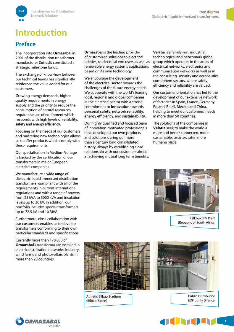
PrefaceThe incorporation into Ormazabal in 2001 of the distribution transformer manufacturer Cotradis constituted a strategic milestone for us.
The exchange of know-how between our technical teams has significantly reinforced the value added for our customers.
Growing energy demands, higher quality requirements in energy supply and the priority to reduce the consumption of natural resources require the use of equipment which responds with high levels of reliability, safety and energy efficiency.
Focusing on the needs of our customers and mastering new technologies allows us to offer products which comply with these requirements.
Our specialisation in Medium Voltage is backed by the certification of our transformers in major European electrical companies.
We manufacture a wide range of dielectric liquid immersed distribution transformers, compliant with all of the requirements in current international regulations and with a range of powers from 25 kVA to 5000 kVA and insulation levels up to 36 kV. In addition, our portfolio includes special transformers up to 72.5 kV and 10 MVA.
Furthermore, close collaboration with our customers enables us to develop transformers conforming to their own particular standards and specifications.
Currently more than 170,000 of Ormazabal’s transforma are installed in electric distribution networks, industry, wind farms and photovoltaic plants in more than 20 countries.
Ormazabal is the leading provider of customized solutions to electrical utilities, to electrical end users as well as renewable energy systems applications based on its own technology.
We encourage the development of the electrical sector towards the challenges of the future energy needs. We cooperate with the world’s leading local, regional and global companies in the electrical sector with a strong commitment to innovation towards personal safety, network reliability, energy efficiency, and sustainability.
Our highly qualified and focused team of innovation-motivated professionals have developed our own products and solutions during our more than a century long consolidated history, always by establishing close relationship with our customers aimed at achieving mutual long term benefits.
Velatia is a family-run, industrial, technological and benchmark global group which operates in the areas of electrical networks, electronics and communication networks as well as in the consulting, security and aeronautics component sectors, where safety, efficiency and reliability are valued.
Our customer orientation has led to the development of our extensive network of factories in Spain, France, Germany, Poland, Brazil, Mexico and China, helping to meet our customers’ needs in more than 50 countries.
The solutions of the companies in Velatia seek to make the world a more and better connected, more sustainable, smarter, safer, more humane place.
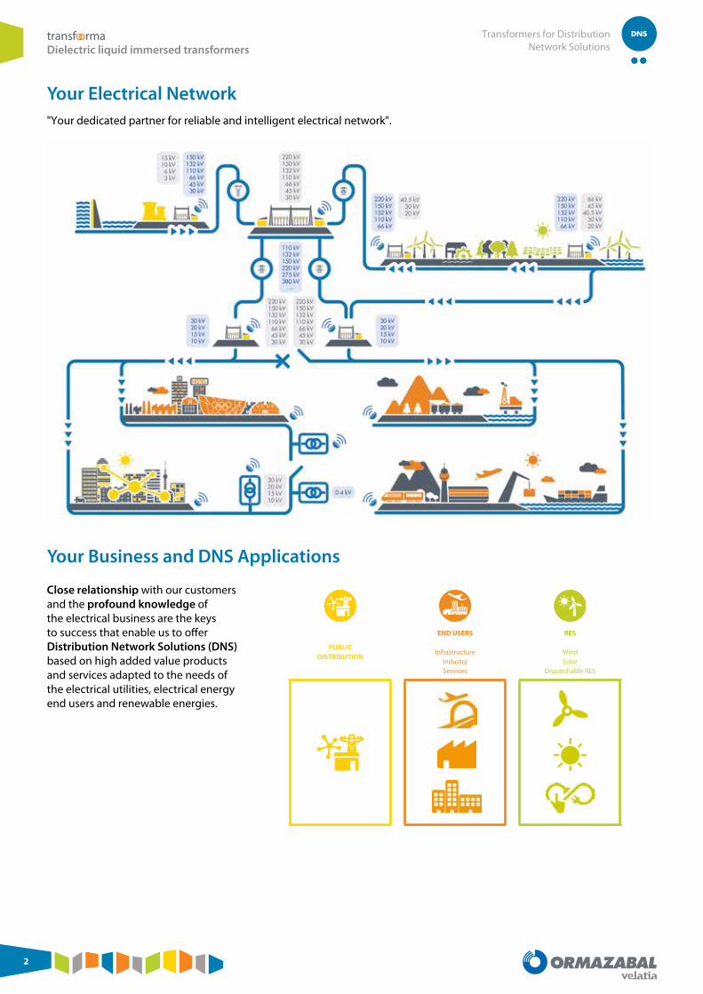
Your Electrical Network"Your dedicated partner for reliable and intelligent electrical network".
Your Business and DNS Applications
PUBLIC DISTRIBUTION
END USERS
Infrastructure Industry Services
RES
Wind Solar
Dispatchable RES
Close relationship with our customers and the profound knowledge of the electrical business are the keys to success that enable us to offer Distribution Network Solutions (DNS) based on high added value products and services adapted to the needs of the electrical utilities, electrical energy end users and renewable energies.
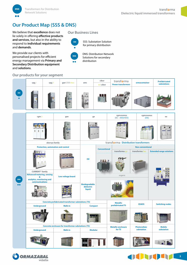
Our Product Map (SSS & DNS)We believe that excellence does not lie solely in offering effective products and services, but also in the ability to respond to individual requirements and demands.
We provide our clients with personalised projects for efficient energy management via Primary and Secondary Distribution equipment and solutions.
Our Business Lines
SSS: Substation Solution for primary distribution
DNS: Distribution Network Solutions for secondary distribution
Our products for your segment
cpg.1 cpg.0 gae1250kmax amccibor transfoorma
Power transformersormacontainer Prefabricated
substationsnvl.cibor
cgm.3 gae ga cgmcosmos [IEC - ANSI/IEEE]
cgmcosmos [HN]
ea
ekorsys family transfoorma Distribution transformers
Protection, automation and control
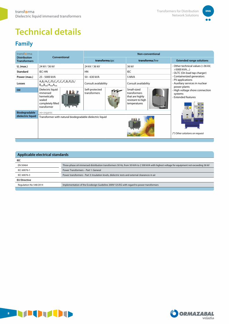
Oil
ConventionalNon-conventional
transforma.tpc transforma.fine Extended range solutions
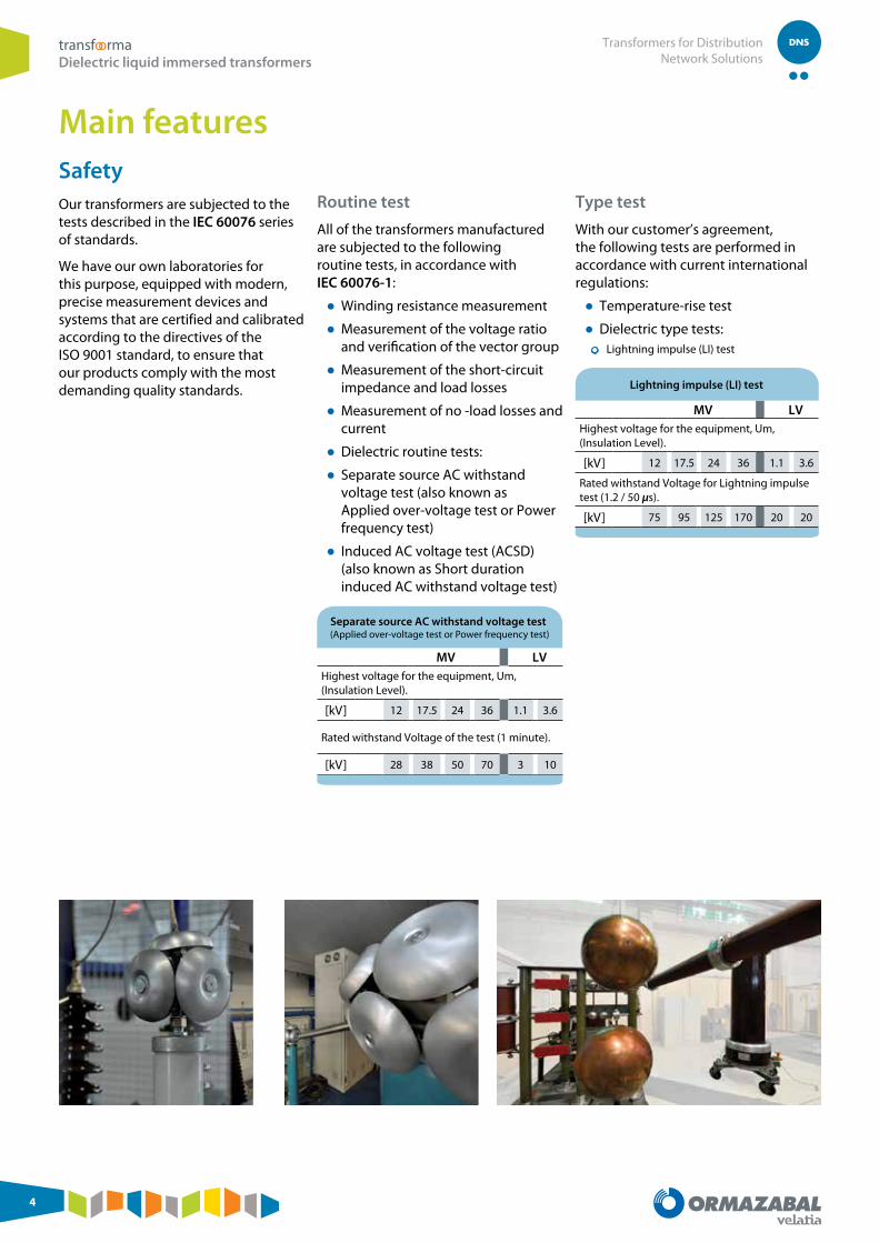
SafetyOur transformers are subjected to the tests described in the IEC 60076 series of standards.
We have our own laboratories for this purpose, equipped with modern, precise measurement devices and systems that are certified and calibrated according to the directives of the ISO 9001 standard, to ensure that our products comply with the most demanding quality standards.
Routine test
All of the transformers manufactured are subjected to the following routine tests, in accordance with IEC 60076-1:
● Winding resistance measurement
● Measurement of the voltage ratio and verification of the vector group
● Measurement of the short-circuit impedance and load losses
● Measurement of no -load losses and current
● Dielectric routine tests:
● Separate source AC withstand voltage test (also known as Applied over-voltage test or Power frequency test)
● Induced AC voltage test (ACSD) (also known as Short duration induced AC withstand voltage test)
Separate source AC withstand voltage test(Applied over-voltage test or Power frequency test)
MV LVHighest voltage for the equipment, Um, (Insulation Level).
[kV] 12 17.5 24 36 1.1 3.6
Rated withstand Voltage of the test (1 minute).
[kV] 28 38 50 70 3 10
Type test
With our customer’s agreement, the following tests are performed in accordance with current international regulations:
● Temperature-rise test
● Dielectric type tests: ● Lightning impulse (LI) test
Lightning impulse (LI) test
MV LVHighest voltage for the equipment, Um, (Insulation Level).
[kV] 12 17.5 24 36 1.1 3.6
Rated withstand Voltage for Lightning impulse test (1.2 / 50 μs).
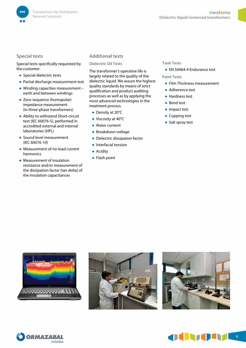
Special tests specifically requested by the customer:
● Special dielectric tests
● Partial discharge measurement test
● Winding capacities measurement – earth and between windings
● Zero-sequence (homopolar) impedance measurement (in three-phase transformers)
● Ability to withstand Short-circuit test (IEC 60076-5), performed in accredited external and internal laboratories (HPL)
● Sound level measurement (IEC 60076-10)
● Measurement of no-load current harmonics
● Measurement of insulation resistance and/or measurement of the dissipation factor (tan delta) of the insulation capacitances
Additional tests
Dielectric Oil Tests
The transformer’s operative life is largely related to the quality of the dielectric liquid. We assure the highest quality standards by means of strict qualification and product auditing processes as well as by applying the most advanced technologies in the treatment process.
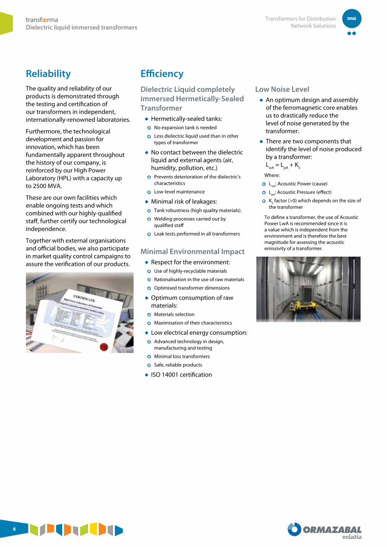
ReliabilityThe quality and reliability of our products is demonstrated through the testing and certification of our transformers in independent, internationally-renowned laboratories.
Furthermore, the technological development and passion for innovation, which has been fundamentally apparent throughout the history of our company, is reinforced by our High Power Laboratory (HPL) with a capacity up to 2500 MVA.
These are our own facilities which enable ongoing tests and which combined with our highly-qualified staff, further certify our technological independence.
Together with external organisations and official bodies, we also participate in market quality control campaigns to assure the verification of our products.
● Hermetically-sealed tanks: ● No expansion tank is needed
● Less dielectric liquid used than in other types of transformer
● No contact between the dielectric liquid and external agents (air, humidity, pollution, etc.) ● Prevents deterioration of the dielectric’s
characteristics
● Low-level maintenance
● Minimal risk of leakages: ● Tank robustness (high quality materials).
● Welding processes carried out by qualified staff
● Leak tests performed in all transformers
Minimal Environmental Impact ● Respect for the environment: ● Use of highly-recyclable materials
● Rationalisation in the use of raw materials
● Optimised transformer dimensions
● Optimum consumption of raw materials: ● Materials selection
● Maximisation of their characteristics
● Low electrical energy consumption: ● Advanced technology in design,
manufacturing and testing
● Minimal loss transformers
● Safe, reliable products
● ISO 14001 certification
Low Noise Level ● An optimum design and assembly of the ferromagnetic core enables us to drastically reduce the level of noise generated by the transformer.
● There are two components that identify the level of noise produced by a transformer: L
wA = L
pA + K
S
Where:
● LwA
: Acoustic Power (cause)
● LpA
: Acoustic Pressure (effect)
● KS factor (>0) which depends on the size of
the transformer
To define a transformer, the use of Acoustic Power LwA is recommended since it is a value which is independent from the environment and is therefore the best magnitude for assessing the acoustic emissivity of a transformer.
PCB Free ● Our transformers are only manufactured using new components and without any PCBs, in strict compliance with current regulations
Electromagnetic Compatibility
Our transformers are passive elements in terms of electromagnetic compatibility. In other words, they work satisfactorily without adding electromagnetic noise that is intolerable for equipment in their surroundings and they withstand such interference caused by other devices.
The currents that circulate through the conductors connected to the transformers, especially low-voltage ones, can cause significant electromagnetic fields. The installation designer must make sure that these cables are laid such that the fields are minimised or, if necessary, measures must be adopted to limit their effects.
Sustainability Sustainability, understood as the best compromise between satisfying social demands, caring for the environment and financial aspects.
Social Demands ● Safety of people and goods
● Continuity of service
Financial Aspects ● Optimum use of raw materials
● Longer equipment life, endurance and robustness
● Equipment adaptable to network evolution
● Equipment durability
Caring for the Environment ● Reduction in the volume of dielectric liquid
● Minimal dimensions
● Minimal losses in the transformer
● Low risk of oil leakage
● Non-aggressive for the surrounding environment
● Recyclability
Ecodesign
Ormazabal complies with the requirements of the Ecodesigndirective from the European Commission (No 548 / 2014) that defines the guideline for the environmentally friendly design of the transformers in Europe.
This regulation applies to all the transformers placing on the market or put into service from July 2015 throughout the European Union and doesn’t affect the products to be exported outside Europe.When supplied within the EU, this equipment will bear the CE mark as proof of compliance with European Union directives.
The Ormazabal distribution and power transformers are being developed to contribute to commitment of this directive, that is, to improve energy efficiency and environmental performance.
Continuous innovationOur commitment to innovation places us at the technological forefront of Europe.
Therefore our products meet the most demanding worldwide requirements and are certified by internationally renowned laboratories.
Recently we have extended our product range to 5 MVA and also we have developed several new transformers for different applications: transforma.fine for wind power generation, transformers with on-load tap changer, transformers for high voltage shore conection systems, etc. as well as transformers with a greater variety of lower losses.
Technical data ● Three-phase transformers, for indoor or outdoor installation
● Dielectric liquid immersed transformers: Hermetically- sealed completely immersed in oil in accordance with standard IEC 60296
● ONAN cooling
● Colour: RAL 7033 (other colours under request)
● Conventional transformers: ● From 25 to 5000 kVA
● Insulation level: 24 and 36 kV
The data and values shown correspond to the normal service conditions referred to in standard IEC 60076-1.
For other configurations, please contact Ormazabal.
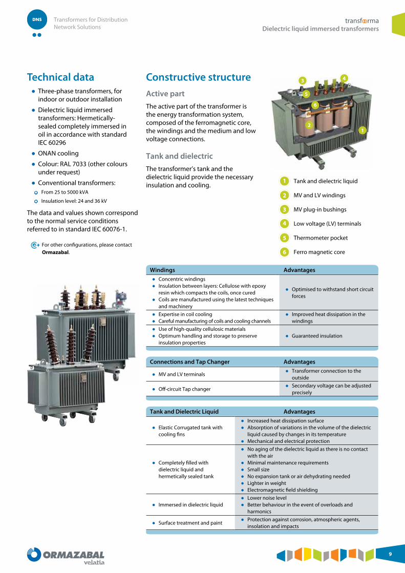
Constructive structure
Active part
The active part of the transformer is the energy transformation system, composed of the ferromagnetic core, the windings and the medium and low voltage connections.
Tank and dielectric
The transformer’s tank and the dielectric liquid provide the necessary insulation and cooling.
Windings Advantages
● Concentric windings ● Insulation between layers: Cellulose with epoxy
resin which compacts the coils, once cured ● Coils are manufactured using the latest techniques
and machinery
● Optimised to withstand short circuit forces
● Expertise in coil cooling ● Careful manufacturing of coils and cooling channels
● Improved heat dissipation in the windings
● Use of high-quality cellulosic materials ● Optimum handling and storage to preserve
insulation properties ● Guaranteed insulation
Connections and Tap Changer Advantages
● MV and LV terminals ● Transformer connection to the
outside
● Off-circuit Tap changer ● Secondary voltage can be adjusted
precisely
Tank and Dielectric Liquid Advantages
● Elastic Corrugated tank with cooling fins
● Increased heat dissipation surface ● Absorption of variations in the volume of the dielectric
liquid caused by changes in its temperature ● Mechanical and electrical protection
● Completely filled with dielectric liquid and hermetically sealed tank
● No aging of the dielectric liquid as there is no contact with the air
● Minimal maintenance requirements ● Small size ● No expansion tank or air dehydrating needed ● Lighter in weight ● Electromagnetic field shielding
● Immersed in dielectric liquid ● Lower noise level ● Better behaviour in the event of overloads and
harmonics
● Surface treatment and paint ● Protection against corrosion, atmospheric agents,
Dielectric liquids ● Mineral oil: Uninhibited mineral insulating oil according to IEC 60296
● Bioelectra®: Natural, biodegradable ester for application in organic transformers. Class K with fire point greater than 300°C
● Dielectric liquid silicone according to the IEC 60836 standard, Class K with fire point greater than 300°C
● Synthetic biodegradable ester for application in electrical transformers according to the IEC 61099 standard
organic transformers
Ormazabal offers, as part of its range of dielectric liquid immersed transformers, the organic transformers, which are characterised by the use of a natural biodegradable ester as a dielectric.
This natural ester Bioelectra® developed and patented by Ormazabal is a dielectric coolant liquid obtained from vegetal oils and made without antioxidant additives.
Its excellent antioxidant capacity is based on its special composition and a specific refining process that allows it to maintain its natural antioxidants.
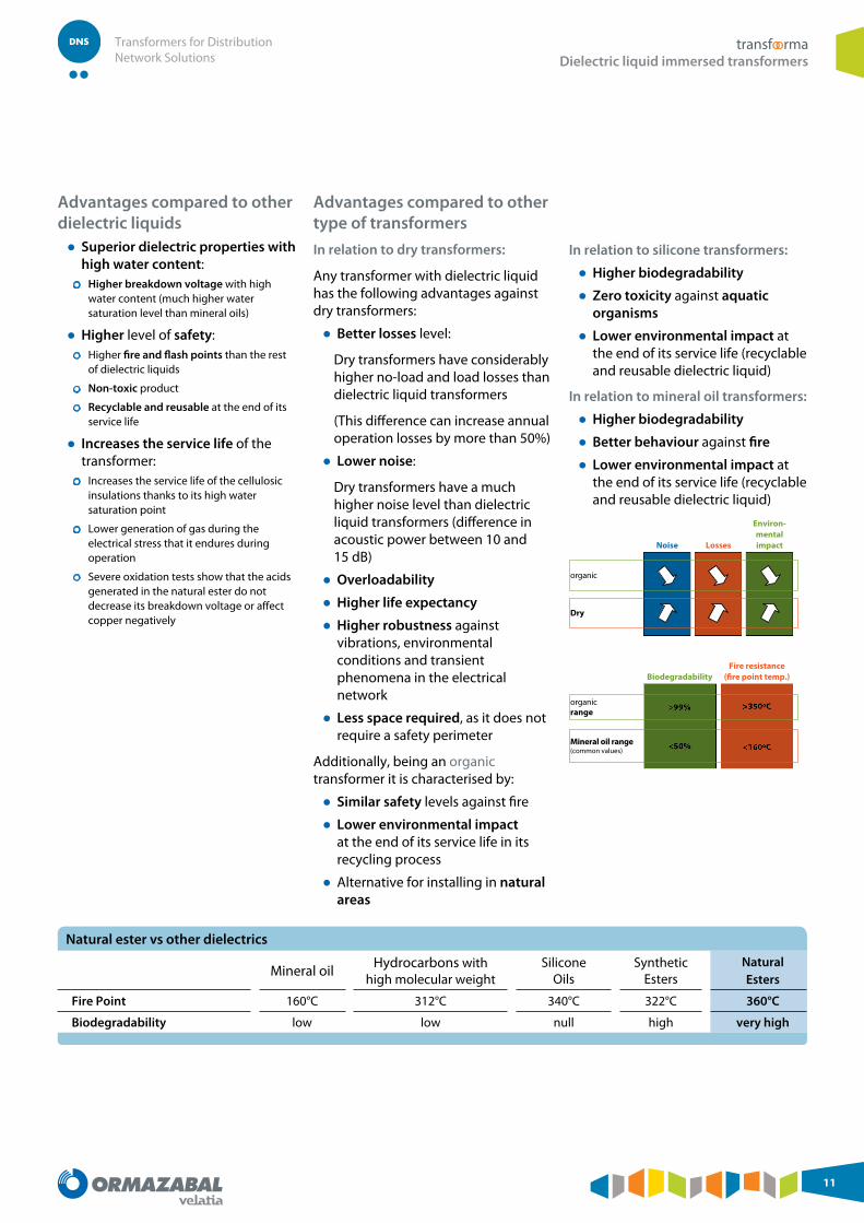
Natural ester features ● Excellent dielectric properties: It has a high water saturation point, which allows it to maintain high breakdown voltage values with a high water content
● High fire resistance: High flash point (>300°C) and fire point (>350°C), much higher than those of mineral oils. It is classified as a K class liquid (Fire point > 300°C) according to Standard IEC 61100. Better behaviour against fire than mineral oil transformers
● High biodegradability in ground and water due to its natural composition
● It is not ecotoxic
● Long service life: It prolongs the life of the cellulosic insulations thanks to its high water retention capacity
● Recyclable and reusable in other favourable environmental products (biodiesel) at the end of its service life
● The electrical characteristics and dimensions of the transformer are not affected
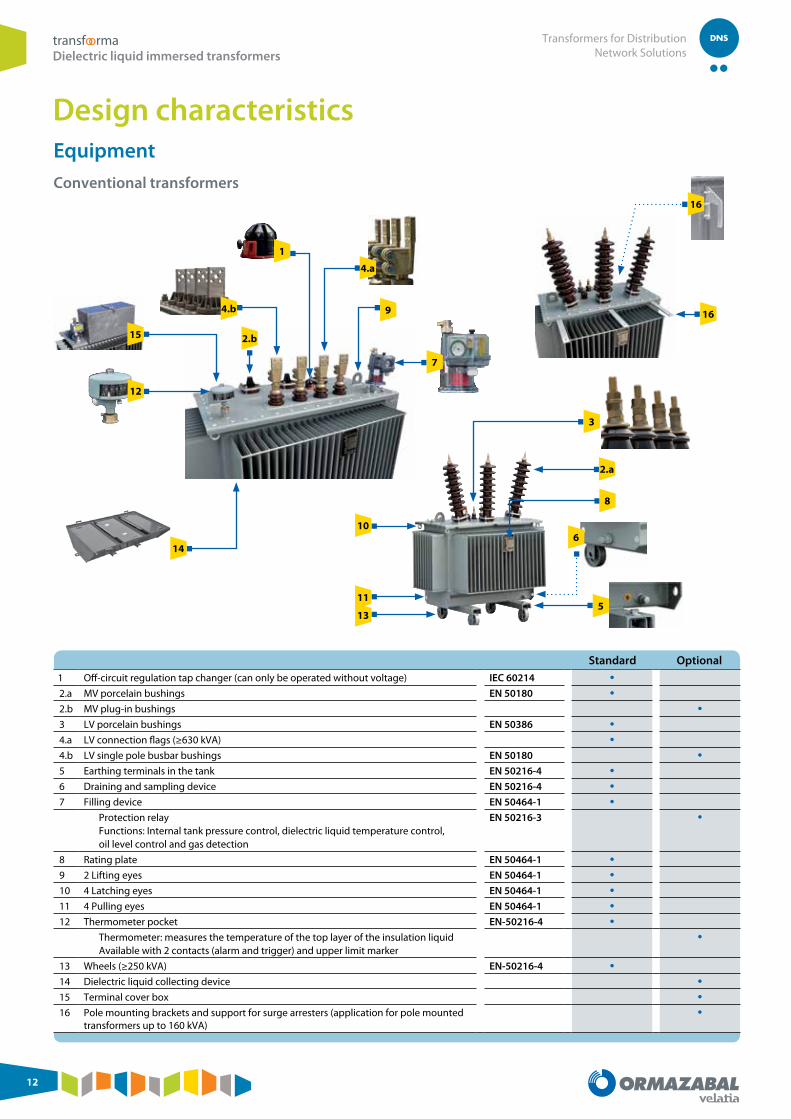
Standard Optional1 Off-circuit regulation tap changer (can only be operated without voltage) IEC 60214 •2.a MV porcelain bushings EN 50180 •2.b MV plug-in bushings •3 LV porcelain bushings EN 50386 •4.a LV connection flags (≥630 kVA) •4.b LV single pole busbar bushings EN 50180 •5 Earthing terminals in the tank EN 50216-4 •6 Draining and sampling device EN 50216-4 •7 Filling device EN 50464-1 •
Protection relay Functions: Internal tank pressure control, dielectric liquid temperature control, oil level control and gas detection
EN 50216-3 •
8 Rating plate EN 50464-1 •9 2 Lifting eyes EN 50464-1 •10 4 Latching eyes EN 50464-1 •11 4 Pulling eyes EN 50464-1 •12 Thermometer pocket EN-50216-4 •
Thermometer: measures the temperature of the top layer of the insulation liquid Available with 2 contacts (alarm and trigger) and upper limit marker
•
13 Wheels (≥250 kVA) EN-50216-4 •14 Dielectric liquid collecting device •15 Terminal cover box •16 Pole mounting brackets and support for surge arresters (application for pole mounted
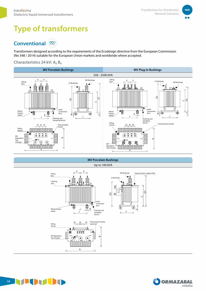
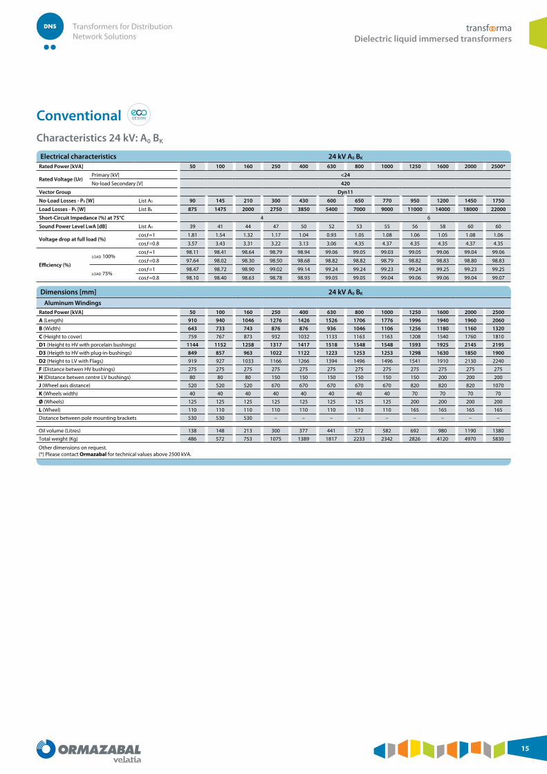
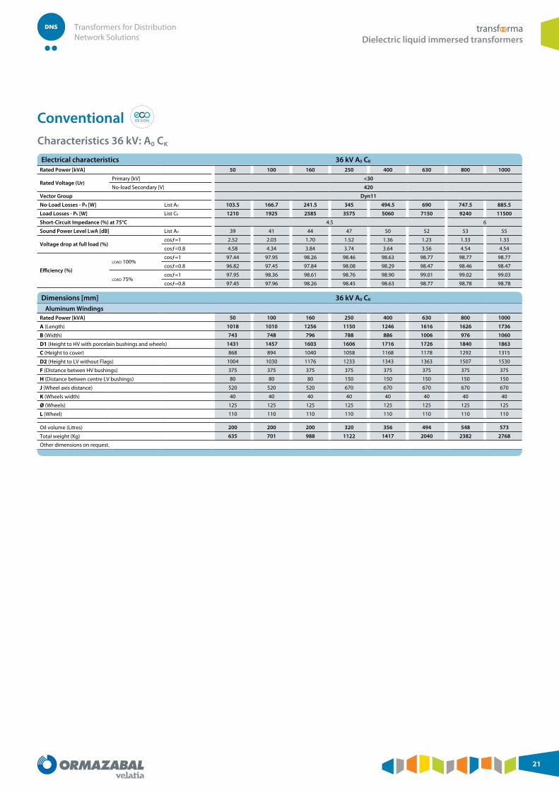
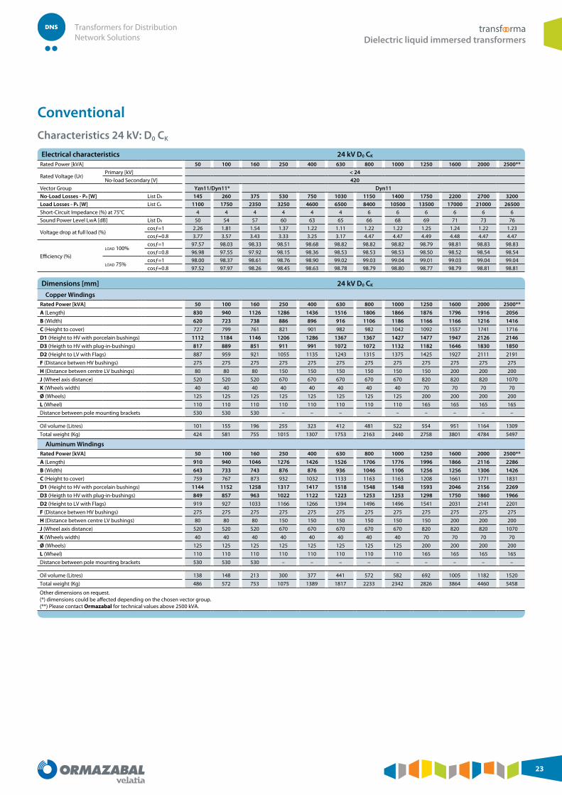
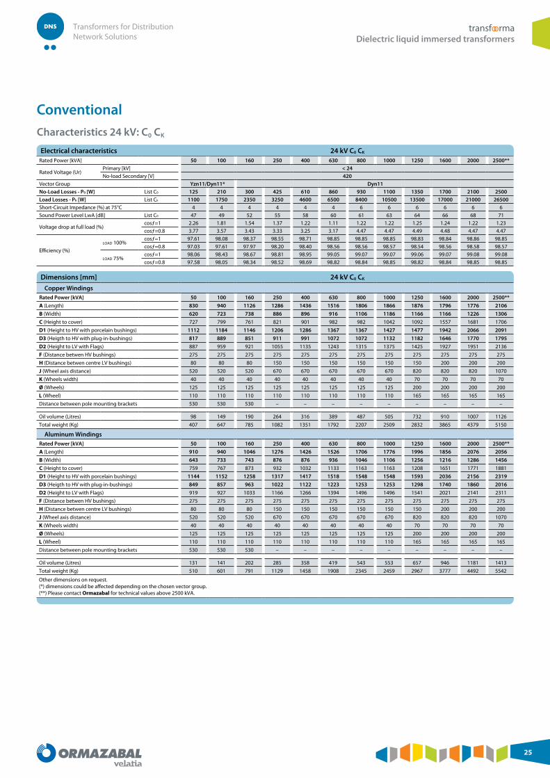
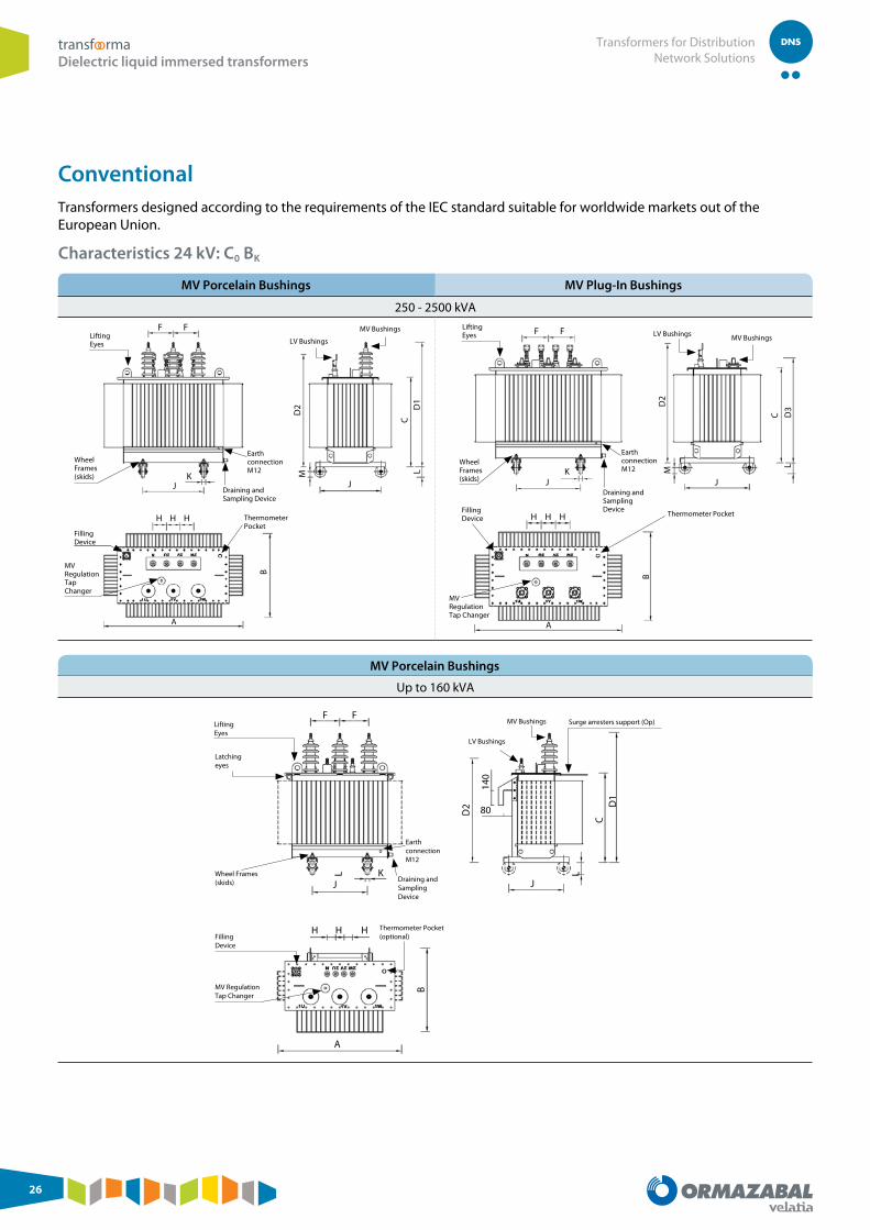
Conventional Transformers designed according to the requirements of the Ecodesign directive from the European Commission (No 548 / 2014) suitable for the European Union markets and worldwide where accepted.
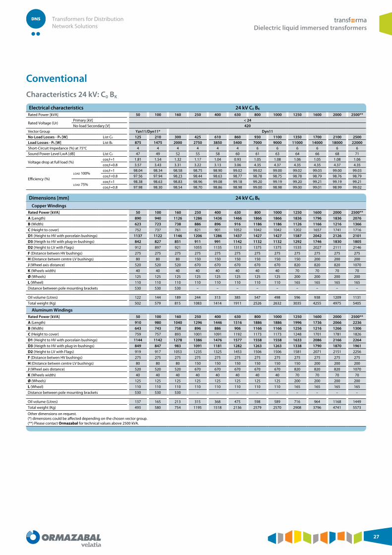
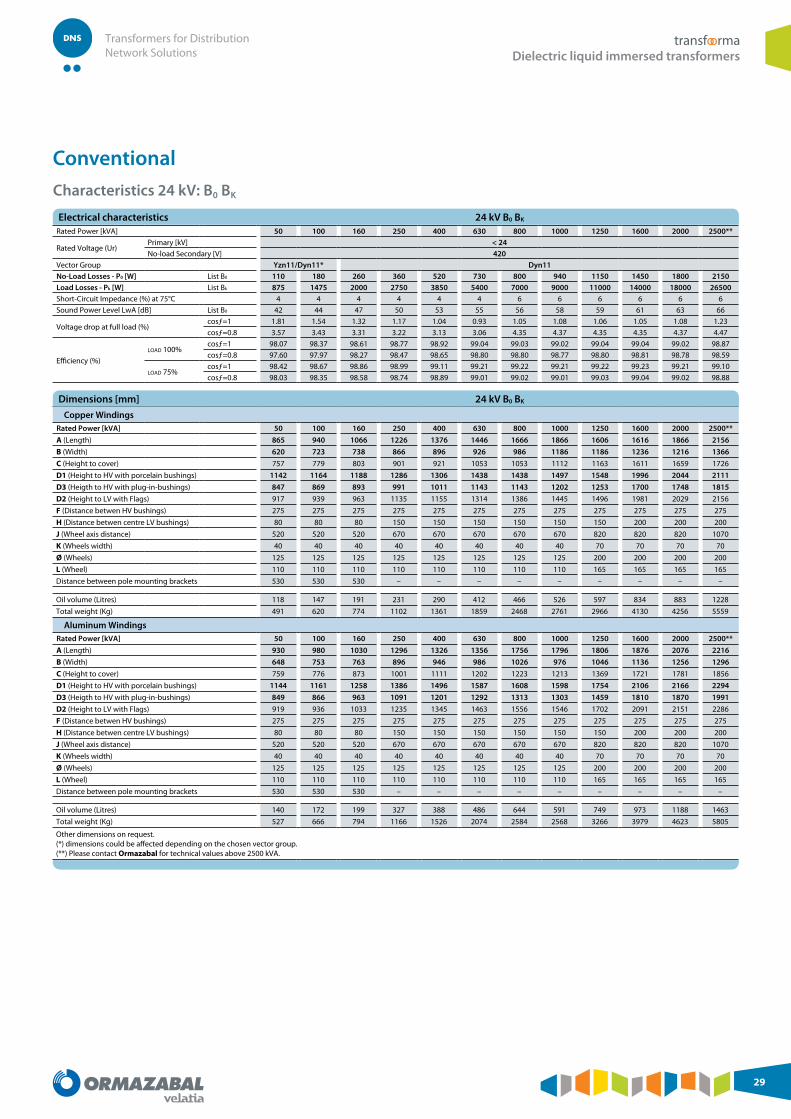
Characteristics 24 kV: A0 BK
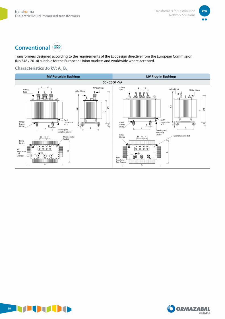
MV Porcelain Bushings MV Plug-In Bushings
250 - 2500 kVA
Lifting Eyes LV Bushings
MV Bushings
Wheel Frames (skids)
Thermometer Pocket
MV Regulation Tap Changer
Filling Device
Draining and Sampling Device
Earth connectionM12
F
J
H H
A
H
B
F
K
D2
M LC
J
D1
Lifting Eyes LV Bushings MV Bushings
Wheel Frames (skids)
Thermometer Pocket
Draining and Sampling Device
Earth connectionM12
Filling Device
F F
D2
M
LD
3
C
KJ J
H H
AB
H
MV Regulation Tap Changer
MV Porcelain Bushings
Up to 160 kVA
LV Bushings
MV Bushings Surge arresters support (Op) Lifting Eyes
Conventional Transformers designed according to the requirements of the Ecodesign directive from the European Commission (No 548 / 2014) suitable for the European Union markets and worldwide where accepted.
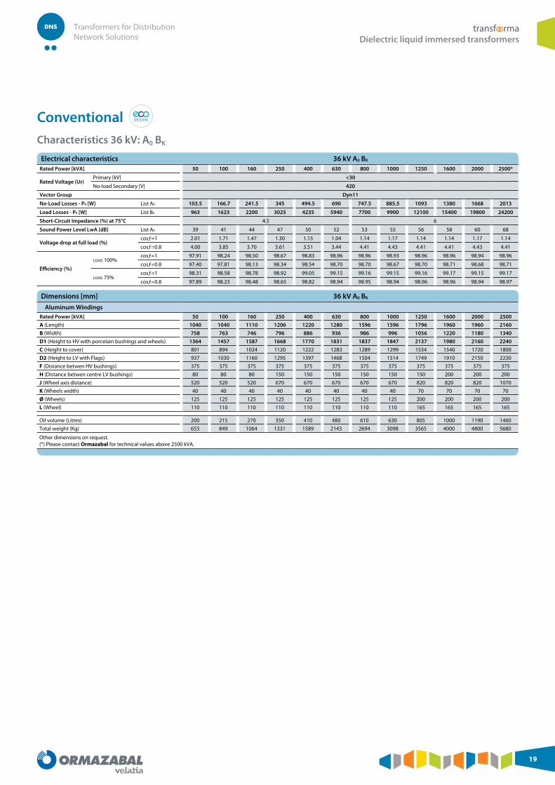
Conventional Transformers designed according to the requirements of the Ecodesign directive from the European Commission (No 548 / 2014) suitable for the European Union markets and worldwide where accepted.
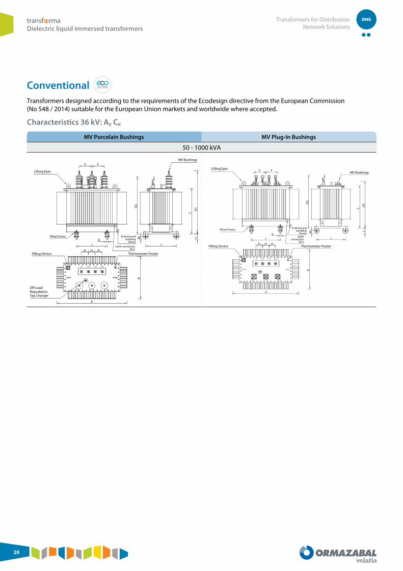
Conventional Transformers designed according to the requirements of the Ecodesign directive from the European Commission (No 548 / 2014) suitable for the European Union markets and worldwide where accepted.
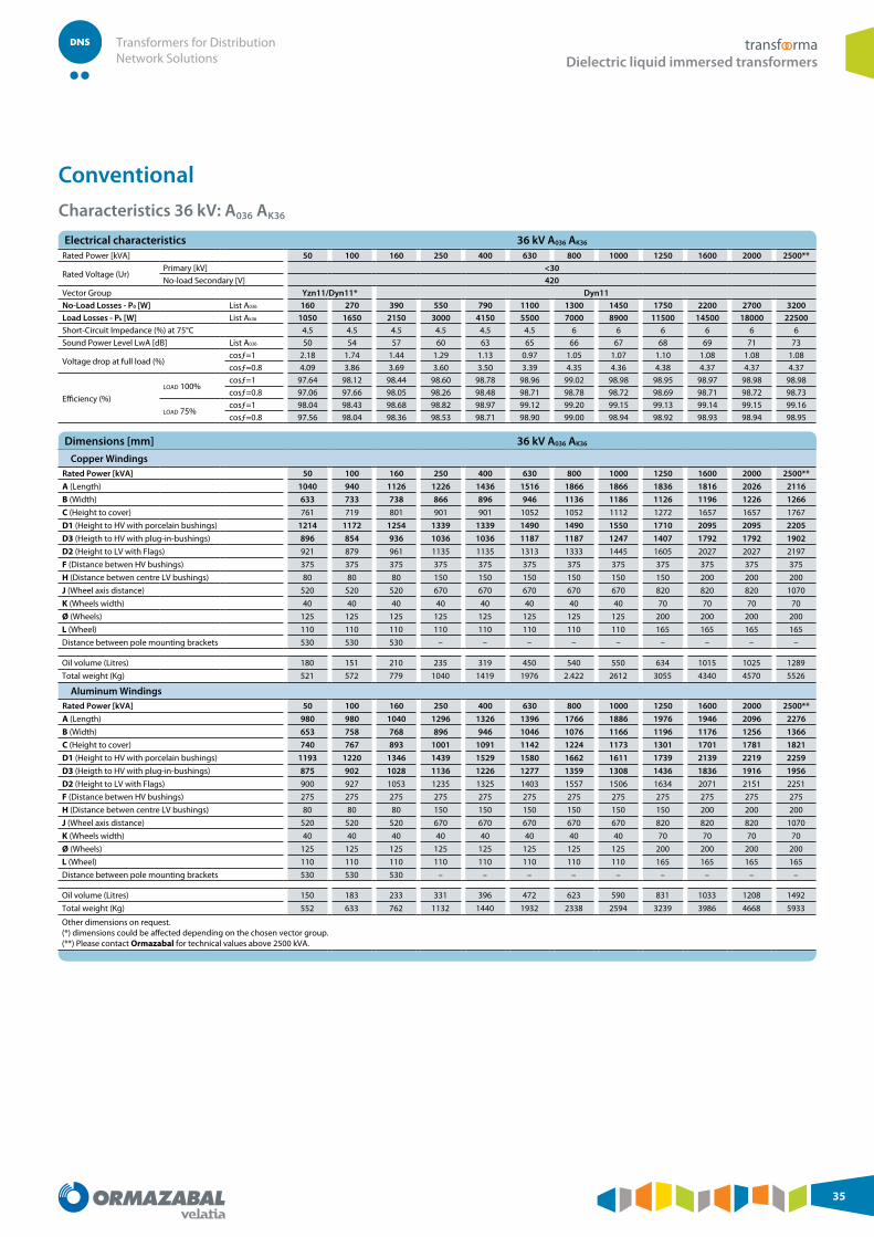
Other dimensions on request. (*) dimensions could be affected depending on the chosen vector group.(**) Please contact Ormazabal for technical values above 2500 kVA.
Other dimensions on request. (*) dimensions could be affected depending on the chosen vector group.(**) Please contact Ormazabal for technical values above 2500 kVA.
Other dimensions on request. (*) dimensions could be affected depending on the chosen vector group.(**) Please contact Ormazabal for technical values above 2500 kVA.
Other dimensions on request. (*) dimensions could be affected depending on the chosen vector group.(**) Please contact Ormazabal for technical values above 2500 kVA.
Other dimensions on request. (*) dimensions could be affected depending on the chosen vector group.(**) Please contact Ormazabal for technical values above 2500 kVA.
Other dimensions on request. (*) dimensions could be affected depending on the chosen vector group.(**) Please contact Ormazabal for technical values above 2500 kVA.
Other dimensions on request. (*) dimensions could be affected depending on the chosen vector group.(**) Please contact Ormazabal for technical values above 2500 kVA.
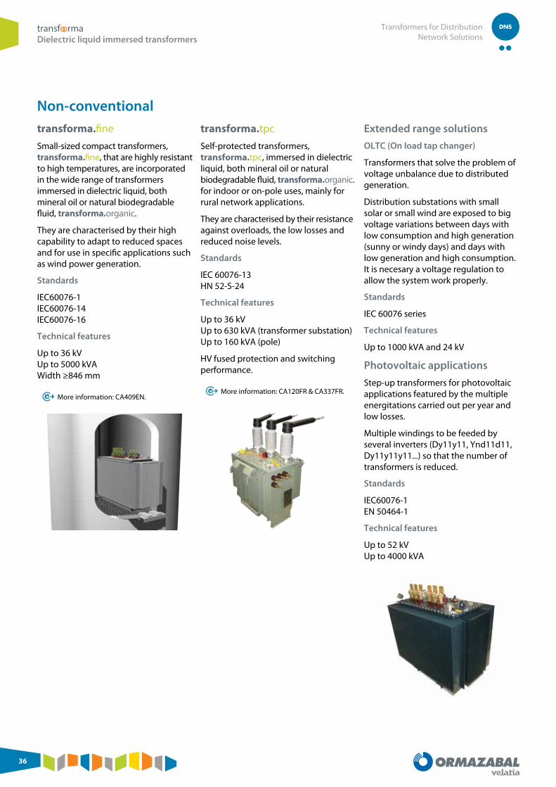
Small-sized compact transformers, transforma.fine, that are highly resistant to high temperatures, are incorporated in the wide range of transformers immersed in dielectric liquid, both mineral oil or natural biodegradable fluid, transforma.organic.
They are characterised by their high capability to adapt to reduced spaces and for use in specific applications such as wind power generation.
Standards
IEC60076-1 IEC60076-14 IEC60076-16
Technical features
Up to 36 kV Up to 5000 kVA Width ≥846 mm
More information: CA409EN.
transforma.tpc
Self-protected transformers, transforma.tpc, immersed in dielectric liquid, both mineral oil or natural biodegradable fluid, transforma.organic. for indoor or on-pole uses, mainly for rural network applications.
They are characterised by their resistance against overloads, the low losses and reduced noise levels.
Standards
IEC 60076-13 HN 52-S-24
Technical features
Up to 36 kV Up to 630 kVA (transformer substation) Up to 160 kVA (pole)
HV fused protection and switching performance.
More information: CA120FR & CA337FR.
Extended range solutions
OLTC (On load tap changer)
Transformers that solve the problem of voltage unbalance due to distributed generation.
Distribution substations with small solar or small wind are exposed to big voltage variations between days with low consumption and high generation (sunny or windy days) and days with low generation and high consumption. It is necesary a voltage regulation to allow the system work properly.
Standards
IEC 60076 series
Technical features
Up to 1000 kVA and 24 kV
Photovoltaic applications
Step-up transformers for photovoltaic applications featured by the multiple energitations carried out per year and low losses.
Multiple windings to be feeded by several inverters (Dy11y11, Ynd11d11, Dy11y11y11...) so that the number of transformers is reduced.
Transformers mutti voltage and multi frequency that allow the adaptation of the electrical supply coming from a generator according to the characteristics of any country.
The different voltages in MV are obtained by:
● Different LV generation voltages
● Different vector groups (changing the vector group tap changer)
● Different tapping (changing the voltage selection tap changer)
● Different % adjustment over the main tap (changing the voltage changeover tap changer)
Standards
IEC60076
Technical features
Up to 5000 kVA and 36 kV
High voltage shore connection systems (HVSC)
Transformers with a very balanced voltage (voltage variations <3%) for complete power solutions to supply energy to ships in harbours (HV shore connection systems).
The solution is based in a containerized compact substation where the transformer is installed.
This turn-key solution is characterized by:
● On load voltage regulation
● Plug and play concept: Extensible cable to plug the facility to ships
● Advanced communication protocol between ship and substation
Standards
IEC60076
ISO80005
Technical features
Up to 10 000 kVA and 52 kV
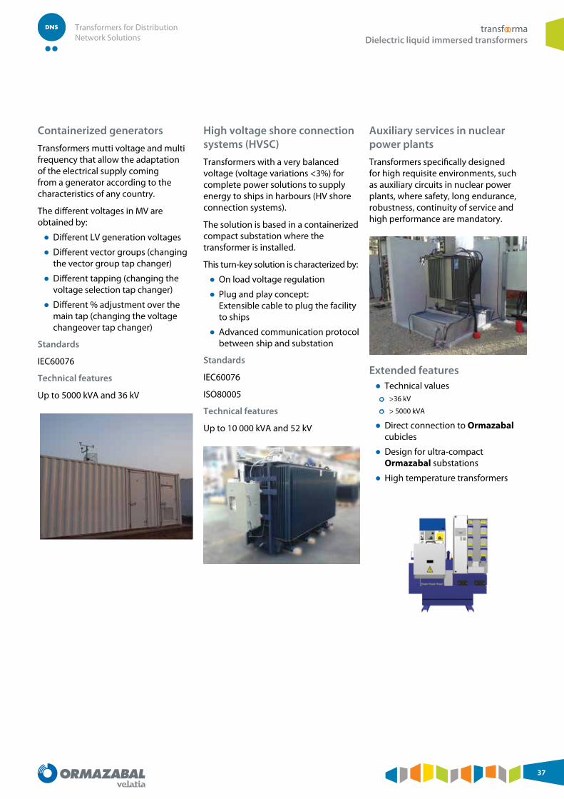
Auxiliary services in nuclear power plants
Transformers specifically designed for high requisite environments, such as auxiliary circuits in nuclear power plants, where safety, long endurance, robustness, continuity of service and high performance are mandatory.
Handling, installation and after salesHandling Conventional transformers have fourbracing eyes located on the corners for transportation and so prevent damage to the cooling elements.
The transformers can be transported and handled using a forklift truck, crane or their own wheels:
Forklift truck
Transformer fitted and fastened to a pallet.
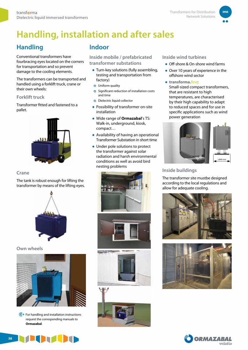
Crane
The tank is robust enough for lifting the transformer by means of the lifting eyes.
Own wheels
For handling and installation instructions request the corresponding manuals to Ormazabal.
Indoor
Inside mobile / prefabricated transformer substations
● Turn-key solutions (fully assembling, testing and transportation from factory) ● Uniform quality
● Significant reduction of installation costs and time
● Dielectric liquid collector
● Possibility of transformer on-site installation
● Wide range of Ormazabal’s TS: Walk-in, underground, kiosk, compact…
● Availability of having an operational Transformer Substation in short time
● Under pole solutions to protect the transformer against solar radiation and harsh environmental conditions as well as avoid bird nesting problems
● Over 10 years of experience in the offshore wind sector
● transforma.fine: Small-sized compact transformers, that are resistant to high temperatures, are characterised by their high capability to adapt to reduced spaces and for use in specific applications such as wind power generation
≥846 mm
Inside buildings
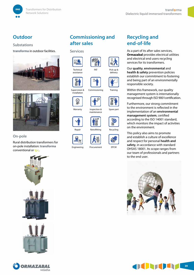
The transformer site mustbe designed according to the local regulations and allow for adequate cooling.
Rural distribution transformers for on-pole installation: transforma conventional or tpc.
Commissioning and after sales
Services
Technical assistance
FAT Pick-up & delivery
Supervision & installation
Commissioning Training
Warranty Inspection & maintenance
Spare part
Repair Retrofitting Recycling
Engineering Procurement EPCM
Recycling and end-of-lifeAs a part of its after sales services, Ormazabal provides electrical utilities and electrical end users recycling services for its transformers.
Our quality, environmental and health & safety prevention policies establish our commitment to fostering and being part of an environmentally responsible society.
Within this framework, our quality management system is internationally recognised through ISO 9001certification.
Furthermore, our strong commitment to the environment is reflected in the implementation of an environmental management system, certified according to the ISO 14001 standard, which monitors the impact of activities on the environment.
This policy also aims to promote and establish a culture of excellence and respect for personal health and safety, in accordance with standard OHSAS 18001. Its scope ranges from our team of professionals and partners to the end user.