Document No.: M-W2254AE-14.0 ANRITSU CORPORATION MW9077A/A1 OTDR Module Operation Manual For safety and warning information, please read this manual before attempting to use the equipment. Keep this manual with the equipment. 14th Edition
Transcript
Document No.: M-W2254AE-14.0
ANRITSU CORPORATION
MW9077A/A1
OTDR Module
Operation Manual
For safety and warning information, please read this
manual before attempting to use the equipment.
Keep this manual with the equipment.
14th Edition
ii
Safety Symbols
To prevent the risk of personal injury or loss related to equipment malfunction, Anritsu Corporation uses the
following safety symbols to indicate safety-related information. Ensure that you clearly understand the meanings of
the symbols BEFORE using the equipment. Some or all of the following symbols may be used on all Anritsu
equipment. In addition, there may be other labels attached to products that are not shown in the diagrams in this
manual.
Symbols used in manual This indicates a very dangerous procedure that could result in serious injury or death if not performed properly.
This indicates a hazardous procedure that could result in serious injury or death if not performed properly. This indicates a hazardous procedure or danger that could result in light-to-severe injury, or loss related to equipment malfunction, if proper precautions are not taken.
Safety Symbols Used on Equipment and in Manual The following safety symbols are used inside or on the equipment near operation locations to provide information
about safety items and operation precautions. Ensure that you clearly understand the meanings of the symbols and
take the necessary precautions BEFORE using the equipment.
This indicates a prohibited operation. The prohibited operation is indicated symbolically in or near the barred circle.
This indicates an obligatory safety precaution. The obligatory operation is
indicated symbolically in or near the circle. This indicates a warning or caution. The contents are indicated symbolically in or
near the triangle. This indicates a note. The contents are described in the box. These indicate that the marked part should be recycled.
ALWAYS refer to the operation manual when working near locations
at which the alert mark shown on the left is attached. If the advice in
the operation manual is not followed, there is a risk of personal injury
or reduced equipment performance. The alert mark shown on the left
may also be used with other marks and descriptions to indicate other
dangers.
Overvoltage Category
This equipment complies with overvoltage category II defined in IEC
61010. DO NOT connect this equipment to the power supply of
overvoltage category III or IV.
Laser radiation warning
NEVER look directly into the cable connector on the equipment
nor into the end of a cable connected to the equipment. There is a
risk of injury if laser radiation enters the eye.
The Laser Safety label is attached to the equipment for safety use
as indicated in "Laser Safety" later in this section.
Only qualified service personnel with a knowledge of electrical fire and
shock hazards should service this equipment. This equipment cannot
be repaired by the operator. DO NOT attempt to remove the
equipment covers or unit covers or to disassemble internal
components. In addition, there is a risk of damage to precision
components.
The performance-guarantee seal verifies the integrity of the
equipment. To ensure the continued integrity of the equipment, only
Anritsu service personnel, or service personnel of an Anritsu sales
representative, should break this seal to repair or calibrate the
equipment. Be careful not to break the seal by opening the
equipment or unit covers.If the performance-guarantee seal is
broken by you or a third party, the performance of the equipment
cannot be guaranteed.
Repair
Calibration
For Safety
iv
WARNING
This equipment should always be positioned in the correct manner. If
the cabinet is turned on its side, etc., it will be unstable and may be
damaged if it falls over as a result of receiving a slight mechanical
shock.
Always set up the equipment in a position where the power switch
can be reached without difficulty.
Falling Over
For Safety
v
Class 1 indicates the danger degree of the laser radiation specified
below according to IEC 60825-1: 2007.
Class 1: Lasers that are safe under reasonably foreseeable conditions of operation, including the use of optical instruments for intrabeam viewing.
Class I indicates the degree of danger of the laser radiation outlined
below as defined by 21 CFR 1040.10.
Class I: Class I levels of laser radiation are not considered to be hazardous.
CAUTION
Use of controls or adjustments or performance of procedures other than those specified herein may result in hazardous radiation exposure.
The use of optical instruments with this product will increase eye
hazard.
For Safety
vi
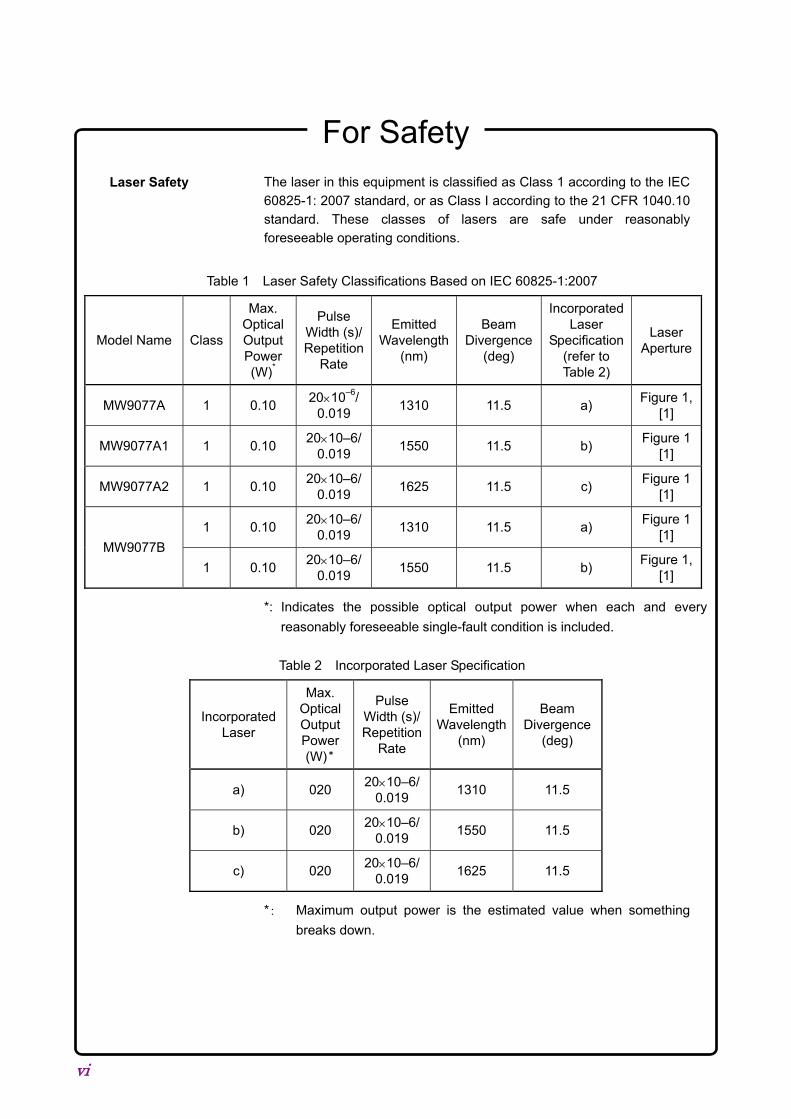
The laser in this equipment is classified as Class 1 according to the IEC
60825-1: 2007 standard, or as Class I according to the 21 CFR 1040.10 standard. These classes of lasers are safe under reasonably foreseeable operating conditions.
Table 1 Laser Safety Classifications Based on IEC 60825-1:2007
Model Name Class
Max. Optical Output Power (W)*
Pulse Width (s)/Repetition
Rate
Emitted Wavelength
(nm)
Beam Divergence
(deg)
Incorporated Laser
Specification (refer to Table 2)
Laser Aperture
MW9077A 1 0.10 2010–6/
0.019 1310 11.5 a)
Figure 1, [1]
MW9077A1 1 0.10 2010–6/
0.019 1550 11.5 b)
Figure 1 [1]
MW9077A2 1 0.10 2010–6/
0.019 1625 11.5 c)
Figure 1 [1]
MW9077B
1 0.10 2010–6/
0.019 1310 11.5 a)
Figure 1 [1]
1 0.10 2010–6/
0.019 1550 11.5 b)
Figure 1, [1]
*: Indicates the possible optical output power when each and every
reasonably foreseeable single-fault condition is included.
Table 2 Incorporated Laser Specification
Incorporated Laser
Max. Optical Output Power (W)*
Pulse Width (s)/Repetition
Rate
Emitted Wavelength
(nm)
Beam Divergence
(deg)
a) 020 2010–6/
0.019 1310 11.5
b) 020 2010–6/
0.019 1550 11.5
c) 020 2010–6/
0.019 1625 11.5
*: Maximum output power is the estimated value when something
breaks down.
Laser Safety
For Safety
vii
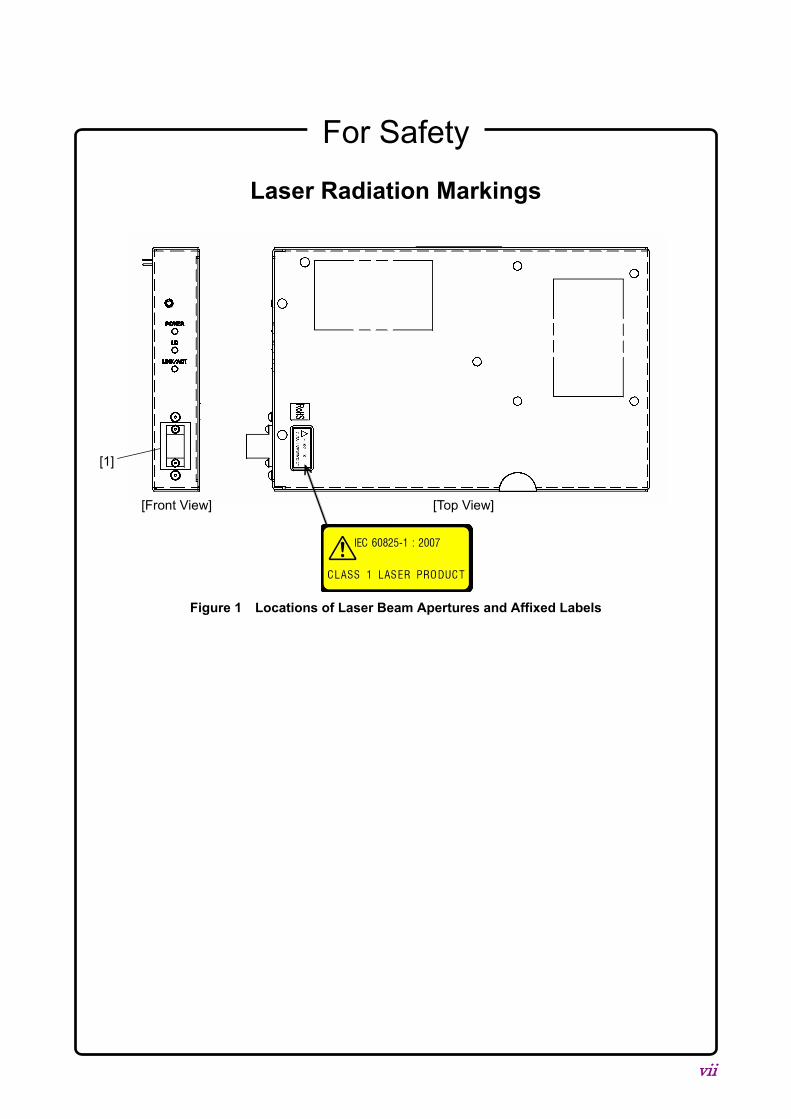
Laser Radiation Markings
[Front View] [Top View]
Figure 1 Locations of Laser Beam Apertures and Affixed Labels
[1]
For Safety
viii
CAUTION
The OTDR Module outputs high-power optical pulses. Disconnect the
communication equipments from the optical fibers before a
measurement, or the optical sensor of the equipment may be broken.
This instrument is designed for an industrial environment.
In a residential environment this instrument may cause radio interference
in which case the user may be required to take adequate measures.
Disconnect from
Communication
Equipments
Use in a residential
environment
ix
Equipment Certificate Anritsu Corporation certifies that this equipment was tested before shipment
using calibrated measuring instruments with direct traceability to public
testing organizations recognized by national research laboratories, including
the National Institute of Advanced Industrial Science and Technology, and
the National Institute of Information and Communications Technology, and
was found to meet the published specifications.
Anritsu Warranty Anritsu Corporation provides the following warranty against stoppages
arising due to manufacturing error, and against problems with operation
occurring even though the procedures outlines in the operation manual were
followed.
Hardware:
Problems occurring within a period of one year from the date of delivery will
be corrected by Anritsu Corporation at no cost to the user.
Software:
Software reported as faulty within a period of 6 months from the date of
delivery will be corrected or replaced by Anritsu Corporation at no cost to the
user.
Following correction or replacement the software will remain under warranty
for either the remainder of 6 months from the date of initial delivery, or for a
period of 30 days, whichever is shorter.
The hardware and software warranties are not valid under any of the
following conditions:
The fault is outside the scope of the warranty conditions separately
described in the operation manual.
The fault is due to mishandling, misuse, or unauthorized modification or
repair of the equipment by the customer.
The fault is due to severe usage clearly exceeding normal usage.
The fault is due to improper or insufficient maintenance by the customer.
The fault is due to natural disaster, including fire, wind, flooding,
earthquake, lightning strike, or volcanic ash, etc.
The fault is due to damage caused by acts of destruction, including civil
disturbance, riot, or war, etc.
The fault is due to explosion, accident, or breakdown of any other
machinery, facility, or plant, etc.
The fault is due to use of non-specified peripheral or applied equipment
or parts, or consumables, etc.
x
The fault is due to use of a non-specified power supply or in a
non-specified installation location.
The fault is due to use in unusual environments(Note).
The fault is due to activities or ingress of living organisms, such as
insects, spiders, fungus, pollen, or seeds.
In addition, this warranty is valid only for the original equipment purchaser. It
is not transferable if the equipment is resold.
Anritsu Corporation shall assume no liability for injury or financial loss of the
customer due to the use of or a failure to be able to use this equipment.
Note:
For the purpose of this Warranty, "unusual environments" means use:
In places of direct sunlight
In dusty places
Outdoors
In liquids, such as water, oil, or organic solvents, and medical fluids, or
places where these liquids may adhere
In salty air or in places where chemically active gases (sulfur dioxide,
hydrogen sulfide, chlorine, ammonia, nitrogen oxide, or hydrogen chloride
etc.) are present
In places where high-intensity static electric charges or electromagnetic
fields are present
In places where abnormal power voltages (high or low) or instantaneous
power failures occur
In places where condensation occurs
In the presence of lubricating oil mists
In places at an altitude of more than 2,000 m
In the presence of frequent vibration or mechanical shock, such as in
cars, ships, or airplanes
Anritsu Corporation Contact In the event that this equipment malfunctions, contact an Anritsu Service and
Sales office. Contact information can be found on the last page of the printed
version of this manual, and is available in a separate file on the CD version.
xi
Notes On Export Management This product and its manuals may require an Export License/Approval by
the Government of the product's country of origin for re-export from your
country.
Before re-exporting the product or manuals, please contact us to confirm
whether they are export-controlled items or not.
When you dispose of export-controlled items, the products/manuals need
to be broken/shredded so as not to be unlawfully used for military purpose.
Notice The following actions are strictly prohibited for all of the software
installed in this product or otherwise provided by Anritsu:
1. Copying, except for archival purposes.
2. Transferring to a third party separately from this product.
3. Analyzing the incorporated software including but not limited to
modifying, decompiling, disassembling, and reverse engineering.
4. Using the software other than in connection with this product.
Cautions against computer virus infection Copying files and data
Only files that have been provided directly from Anritsu or generated
using Anritsu equipment should be copied to the instrument.
All other required files should be transferred by means of USB or
CompactFlash media after undergoing a thorough virus check.
Adding software
Do not download or install software that has not been specifically
recommended or licensed by Anritsu.
Network connections
Ensure that the network has sufficient anti-virus security protection in
place.
xii
Crossed-out Wheeled Bin Symbol Equipment marked with the Crossed-out Wheeled Bin Symbol complies with
council directive 2012/19/EC (the “WEEE Directive”) in European Union.
For Products placed on the EU market after August 13, 2005, please contact
your local Anritsu representative at the end of the product's useful life to
arrange disposal in accordance with your initial contract and the local law.
xiii
RoHS Compliance The European Community Directive 2002/95/EC (the so-called “RoHS
Directive”) limits the use of the hazardous substances in electrical and
electronic equipment.
Anritsu has classified MW9077A/A1 into the component for category 3, as
shown by the following 4 documents:
- Directive 2002/95/EC of the European Parliament and of the Council
- Directive 2002/96/EC of the European Parliament and of the Council
- Frequently Asked Questions on Directive 2002/95/EC on the
Restriction of the Use of certain Hazardous Substances in Electrical
and Electronic Equipment (RoHS) and Directive 2002/96/EC on Waste
Electrical and Electronic Equipment (WEEE) by EUROPEAN
COMMISSION
- DTI RoHS Regulations Government Guidance Notes (June 2006)
Anritsu designates MW9077A/A1 as RoHS compliant. (This component
contains lead, as permitted by the following exemption specified in the
Annex of the RoHS Directive. Lead in solders for servers, storage and
storage array systems, network infrastructure equipment for switching,
signalling, transmission as well as network management for
telecommunications.)
RoHS-Compliant means that:
• firstly, our supplier for the specifically RoHS-compliant products or
product parts has confirmed in writing that it will only supply products or
product parts that are RoHS-compliant;
• secondly, that we have implemented clear processes to confirm and
document the validity of the said supplier’s written confirmation;
• lastly, that notwithstanding the above, we carry out material sample or
content testing if and when Anritsu deems it necessary.
Our suppliers can confirm that their products or product parts are
RoHS-compliant when:
- either the products or product parts do not contain any of the restricted
substances referred to in Article 4 (1) of the RoHS Directive at
concentrations in excess of those permitted under the RoHS Directive;
- or the removal of the restricted substances is not technically possible
and their existence in the products at levels in excess of these
concentrations is allowed as one of the particular applications listed in
the Annex to the RoHS Directive.
xiv
The following notices are applicable to China RoHS Requirements only.
1. 产品中有毒有害物质或元素的名称及含量
(The names and contents of the toxic or hazardous substances or elements
2. 环保使用期限 [The Environment-Friendly Use Period (EFUP)]
这个标记是根据 2006/2/28 公布的「电子信息产品污染控制管理办法」以及
SJ/T 11364-2006「电子信息产品污染控制标识要求」的规定,适用于在中
国销售的电子信息产品的环保使用期限。仅限于在遵守该产品的安全规范及
使用注意事项的基础上,从生产日起算的该年限内,不会因产品所含有害物
质的泄漏或突发性变异,而对环境污染,人身及财产产生深刻地影响。
xv
CE Conformity Marking Anritsu affixes the CE Conformity marking on the following product(s) in
accordance with the Council Directive 93/68/EEC to indicate that they
conform to the EMC and LVD directive of the European Union (EU).
CE marking
1. Product Model Model: MW9077A/A1/A2/B OTDR Module
2. Applied Directive EMC: Directive 2004/108/EC
LVD: Directive 2006/95/EC
3. Applied Standards
EMC: Emission: EN 61326-1: 2013 (Class A)
Immunity: EN 61326-1: 2013 (Table 2)
Performance Criteria*
IEC 61000-4-2 (ESD) B
IEC 61000-4-3 (EMF) A
IEC 61000-4-4 (Burst) B
IEC 61000-4-6 (CRF) A
*: Performance Criteria
A: The equipment shall continue to operate as intended
during and after the test. No degradation of
performance or loss of function is allowed below a
performance level specified by the manufacturer, when
the equipment is used as intended. The performance
level may be replaced by a permissible loss of
performance. If the minimum performance level or the
permissible performance loss is not specified by the
manufacturer, either of these may be derived from the
product description and documentation and what the
user may reasonably expect from the equipment if used
as intended.
B: The equipment shall continue to operate as intended
after the test. No degradation of performance or loss of
function is allowed below a performance level specified
xvi
by the manufacturer, when the equipment is used as
intended. The performance level may be replaced by a
permissible loss of performance. During the test,
degradation of performance is however allowed. No
change of actual operating state or stored data is
allowed. If the minimum performance level or the
permissible performance loss is not specified by the
manufacturer, either of these may be derived from the
product description and documentation and what the
user may reasonably expect from the equipment if used
as intended.
LVD: EN 61010-1: 2010 (Pollution Degree 2)
4. Authorized representative Name: Murray Coleman
Head of Customer Service EMEA
ANRITSU EMEA Ltd.
Address, city: 200 Capability Green, Luton
Bedfordshire, LU1 3LU
Country: United Kingdom
xvii
C-Tick Conformity Marking Anritsu affixes the C-Tick marking on the following product(s) in accordance
with the regulation to indicate that they conform to the EMC framework of
Australia/New Zealand.
C-Tick marking
1. Product Model
Model: MW9077A/A1/A2/B OTDR Module
2. Applied Standards
EMC:Emission: EN 61326-1: 2013 (Class A equipment)
xviii
I
About This Manual This operation manual explains the interface for remote control of the MW9077A/A1 OTDR Module using a connected controller such as a controller board. The features of the OTDR Module are described in Chapter 1 “Outline.”
Refer to the Chapter 3 “Interface” and Chapter 4 “Commands” for information on the type of interface and commands to be used for connecting this equipment. The interface is described in general terms first, and the commands are explained in alphabetical order.
II
Table of Contents
For Safety .............................................................. iii
About This Manual.................................................. I
Chapter 1 Outline ............................................... 1-1 1.1 Overview of MW9077A/A1 OTDR Module ................... 1-2 1.2 Features ........................................................................ 1-3 1.3 Loss, Splice, Return Loss and Total Return Loss
Measurements .............................................................. 1-4 1.4 Linear Approximation Methods LSA/2PA ..................... 1-6
Chapter 2 Before Use ........................................ 2-1 2.1 Equipment Composition ................................................ 2-2 2.2 Names of Parts ............................................................. 2-3 2.3 Installing the OTDR Module .......................................... 2-5 2.4 Connecting the Optical Fiber Cable .............................. 2-7 2.5 Replacing the Optical Connector .................................. 2-8 2.6 Precautions ................................................................. 2-10
Chapter 6 Performance Test and Calibration .. 6-1 6.1 Performance Test ......................................................... 6-2 6.2 Calibration ................................................................... 6-11 6.3 Performance Test Result Record Form ...................... 6-12
Index .................................................. Index-1
IV.
1-1
1
Ou
tline
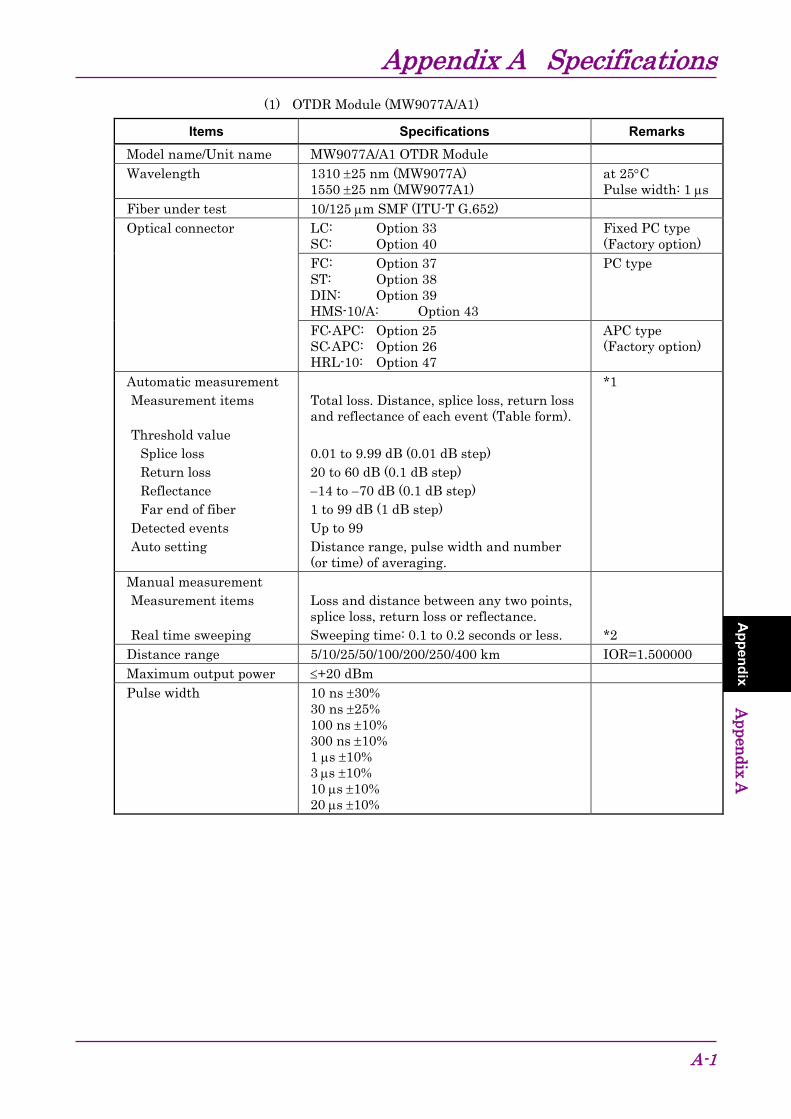
Chapter 1 Outline This section explains the features of the MW9077A/A1 OTDR (Optical Time Domain Reflectometer) Module and the measurement principle. For the performance and function specifications, refer to Appendix A “Specifications.”
1.1 Overview of MW9077A/A1 OTDR Module ................... 1-2 1.1.1 Measuring cable loss and distance .................. 1-2
1.2 Features ........................................................................ 1-3 1.2.1 Automatic search of faults ................................ 1-3 1.2.2 Making high resolution measurements ............. 1-3
1.3 Loss, Splice, Return Loss and Total Return Loss
Measurements .............................................................. 1-4 1.4 Linear Approximation Methods LSA/2PA ..................... 1-6
Chapter 1 Outline
1-2
1.1 Overview of MW9077A/A1 OTDR Module The MW9077A/A1 OTDR Module can be used as an OTDR for supporting measurements at various wavelengths by combining with a interface board and by sending various types of remote commands.
The MW9077A/A1 OTDR Module has been developed for the detection of faults in optical fibers during the maintenance of optical fiber systems. It can be used to measure the total loss, interval loss, and cable length (distance) of an optical fiber system.
An automatic measurement procedure and small lightweight design facilitate its use in maintenance of optical fibers. In addition, the OTDR has an interface (RS-232C and Ethernet) to read the measurement results from a computer connected to the interface board.
Faults are located and losses can be automatically measured by sending remote commands, after setting the measurement conditions.
Automatic fault location
Auto or Manual mode measurement
Detailed measurement of loss and splice loss
1.1.1 Measuring cable loss and distance When laser light of a specific wavelength is introduced into an optical fiber cable from the OTDR, it is scattered as it propagates towards the far end of the cable. A part of this scattered light returns to the OTDR as backscattered light. The intensity of this backscattered light is measured and is used to determine the cable loss. In addition, the time duration (from the introduction of the optical pulse into the fiber till it return to the OTDR from a fault) is used to calculate the distance to the fault. For an accurate measurement, the light (sent into the fiber) must propagate to the far end of the cable and return to the OTDR as the backscattered light before the next optical pulse is sent into the fiber. Therefore, the length of the measured cable is set as “Distance Range.” When the “Distance Range” and “Pulse Width” are set to Auto, the OTDR sets the optimum values of these parameters.
1.2 Features
1-3
1
Ou
tline
1.2 Features 1.2.1 Automatic search of faults
This function is convenient for use when the user does not know the locations of the faults or the length of the fiber. Set the measurement conditions to Auto (Ex. “Distance range” and “Pulse width”). And faults in the cable are detected automatically by measurement. Users can obtain these information of the detected faults by sending a command to ask the measurement result.
Automatically detected result contains the information like:
• Number of faults counted from the OTDR (NO.)
• Distance to the fault from the OTDR
• Splice loss, Return loss, and Total loss for the fault
• Length of the fiber
• Types of the faults ⋅⋅⋅ etc Note:
Results of auto search function: Auto measurement function is a supporting function to reduce the workload of an operator, while it may generate false detection. If false detection is presumed, check the measured waveform.
1.2.2 Making high resolution measurements The number of measured data points can be switched among the following two settings: Normal and Fine. Since 20001/25001 points are sampled in the Fine mode, all errors that could not be detected with the previous equipment can now be detected. It is also possible to measure long distances with high resolution or to make a rough measurement at high speed, as required.
Chapter 1 Outline
1-4
1.3 Loss, Splice, Return Loss and Total Return Loss
Measurements (1) Loss measurement
Using the remote command LOS2?, the loss between X1 and X2 location can be measured.
X1
X2×
(2) Splice and return loss measurement Using the remote commands EVN2?, SPLICE? and REFLCT?, the loss at a connection can be measured. In this measurement, a * marker is set at the connection and a pair of × markers are set on each side of the * marker as shown in the figure below. If Fresnel reflection occurs at the connection, a ∇ marker is set at the peak point.
The four × markers are called ×1, ×2, ×3, and ×4 from the left. The splice loss is determined from the vertical difference at the * marker between straight lines drawn between the ×1 and ×2, and ×3 and ×4 markers.
In this measurement, the distance between the ×1 and ×2 markers and that between the ×3 and ×4 markers, as well as the fiber loss (loss per unit length) are also displayed.
There is a section at the splice where the backscattered light cannot be measured precisely during a time which is equivalent to the pulse width. The distance L shown in the figure on the left is equivalent to this section. Because of the distance L, the fiber loss in the L section is included in the measurement if splice loss is measured using the same method as Loss Measurement.
More detailed explanations of the splice loss measurement and the return loss measurement are given in “Appendix C” and “Appendix D,” respectively.
Splice loss
Loss forcable lengthof L
L
1.3 Loss, Splice, Return Loss and Total Return Loss Measurements
1-5
1
Ou
tline
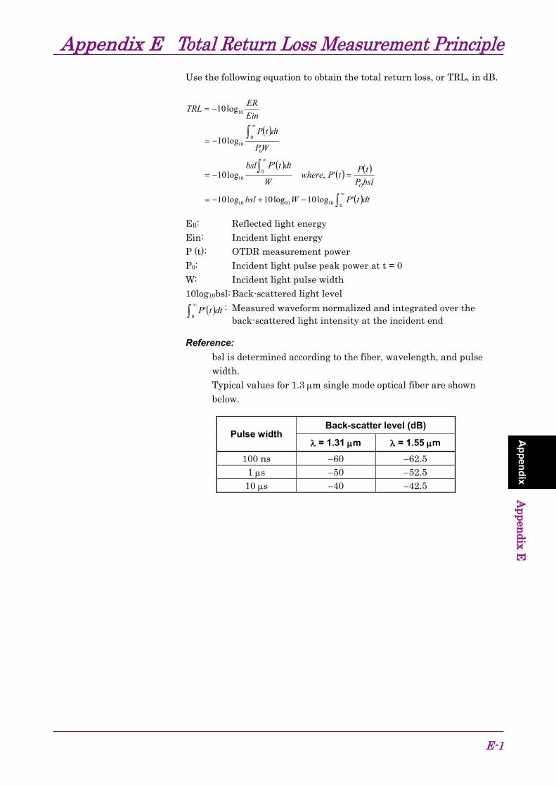
(3) Total return loss measurement Using the remote command AUT?, the total return loss from 0 km to the far end of the fiber cable is measured. The backscattered level used as reference is in the location shown in the following figure.
The standard backscattered level of Total Return Loss
0 km
Refer to “Appendix E” for an explanation of the total return loss measurement.
Chapter 1 Outline
1-6
1.4 Linear Approximation Methods LSA/2PA In the measurement, the loss is calculated by drawing an imaginary line between the two set markers. There are two methods for drawing the line.
LSA (Least Square Approximation) Method
In this method, the line is drawn by computing the least square of the distances from all the measured data between the two markers. This method is useful when the data contains noise. Refer to Appendix B for further details.
×1 ×2
2PA (Two Point Approximation) Method
This method draws a line linking the two measured data points at the two markers.
×1 ×2
Comparison on LSA and 2PA
These two methods are compared when the data contains a lot of noise as follows:
When LSA is selected
When LSA is selected, there is a probability of the occurrence of a large error when a fiber with splice loss is measured along its length.
LSA
Mis-measurement
2PA
Correctmeasurement
1.4 Linear Approximation Methods LSA/2PA
1-7
1
Ou
tline
When 2PA is selected
There is a probability of the occurrence of a large error when the noise is large. An example is shown below.
LSA
Mis-measurement
2PA
Correct measurement
Chapter 1 Outline
1-8.
2-1
2
Before U
se Chapter 2 Before Use
This section provides information that should be thoroughly understood before actually using the OTDR Module. In particular, it explains about the dimensional requirement for controller board.
Refer to Section 3 “Interface” for setup parameters about the RS-232C and the Ethernet connections.
2.2 Names of Parts ............................................................. 2-3 2.3 Installing the OTDR Module .......................................... 2-5
2.3.1 Mechanical dimensions .................................... 2-5 2.3.2 Pin assignment ................................................. 2-6 2.3.3 Specification of power supply ........................... 2-6
2.4 Connecting the Optical Fiber Cable .............................. 2-7 2.5 Replacing the Optical Connector .................................. 2-8 2.6 Precautions ................................................................. 2-10
Chapter 2 Before Use
2-2
2.1 Equipment Composition 2.1.1 Standard composition
The standard composition of the MW9077A/A1 OTDR Module is listed in the following table. After unpacking, check the packing list and make sure that all the components are included. If any part is missing or damaged, contact Anritsu or your Anritsu sales agent immediately.
Table 2.1.1-1 Standard composition
Name Q’ty
Model name or Ordering No.
Remarks
Main unit OTDR Module 1 MW9077A or MW9077A1
Select any model.
Accessories Packing list 1 Operation manual 1 M-W2254AE
2.1.2 Options The following optional parts can be selected for the OTDR Module. Note that all the options need to be installed in an Anritsu factory. For the specifications, refer to Appendix A “Specifications.”
1550 nm filter (MW9077A-01)
This option adds the function of preventing 1500 to 1625 nm optical signals from entering into the OTDR Module.
Maintenance port Connector for maintenance. It is only for Anritsu’s engineer.
Status display LED Power Illuminates when power is supplied to the OTDR
Module.
LD Illuminates when LD is emitting light.
Chapter 2 Before Use
2-4
LINK/ACT Illuminates when the OTDR Module is operated by Ethernet control. Link: LED is lighting. ACT: LED is blinking.
Interface connector Connector to link-up with a controller board. Refer to 2.3 “Installing the OTDR Module” for a pin assignment.
Screw holes Use these holes when securing the OTDR Module on the controller board. Refer to 2.3 “Installing the OTDR Module” for dimensional information.
WARNING NEVER look directry into the laser radiation emitted from
the OTDR I/O connector or the end of the cable connected
to the OTDR. If you do so, the laser light may damage
your eye.
2.3 Installing the OTDR Module
2-5
2
Before U
se
2.3 Installing the OTDR Module This section explains the requirements and setup to install the OTDR Module on the controller board.
2.3.1 Mechanical dimensions The figure below shows the model with option 33 (LC) connector.
3 GND Chassis and four mounting holes are connected to GND.
4 GND
5 I TPIP Ethernet 6 I TPIN Ethernet 7 O TPO
P 8 O TPO
N 9 GND 1
0 GND
11
CD RS-232C 12
RD RS-232C
13
SD 14
ER
15
SG 16
DR
17
RS 18
CS
19
I RESET
TTL level Active “L” Assert Pin-19 for more than 10 ms for Reset.
20
GND
2.3.3 Specification of power supply Power supply (Interface connector pins 1 & 2) for OTDR Module is +12 Vdc ±1 V, 1.5 A max.
2.4 Connecting the Optical Fiber Cable
2-7
2
Before U
se
2.4 Connecting the Optical Fiber Cable Connect the optical fiber cable as shown in the figure below.
The figure below shows the model with option 37 (FC) connector.
WARNING NEVER look into the cable connecting end of the optical
connector of the OTDR or the end of the cable connected
to the OTDR. If you do so, the laser light may damage
your eye.
Chapter 2 Before Use
2-8
2.5 Replacing the Optical Connector This section describes only for the OTDR Module with the user-replacable connector type.
To replace the optical connector, pull the adapter lever towards you until the latch is released. Then, remove the connector by lifting it.
Connector types are shown below for reference.
SCSTHMS-10/ADINFC
interior of theMW9077A/A1
2.5 Replacing the Optical Connector
2-9
2
Before U
se
CAUTION When replacing the optical connector, take care not to
damage the connector and the connecting surface of the
connector.
WARNING NEVER look directory into the laser radiation emitted from
the OUTPUT connector or the end of the cable connected
to the OTDR. If you do so, the laser light may damage
your eye.
Chapter 2 Before Use
2-10.
2.6 Precautions Disconnect from communication equipments
The OTDR Module outputs high-power optical pulses. Disconnect the communication equipments from the optical fibers before a measurement, or the optical sensor of the equipment may be broken.
Limit to the interface
The OTDR Module provides two interfaces such as RS-232C (serial) and Ethernet. However, as there is a limit in the OTDR’s firmware, use only one system when linking up from the controller. It is not assured to control the OTDR coincidentally or dynamically by both means.
As a port for integration with your system, an Ethernet port is more appropriate than a serial one.
Connector cover
The interface connector has a dust-proof cover. Do not remove the cover except when a cable is to be connected to the connector.
Condensation
If the OTDR Module is carried from a low-temperature environment to a warm room, there is a danger of condensation in it. In this case, allow the OTDR to dry completely before turning on its power.
Exposure to extremely high temperature in vehicles
Do not leave the OTDR Module in a vehicle. The ambient remperature may exceed the storage temperature (−40 to +70°C) which may result in the failure of the OTDR. Do not expose the OTDR Module to an extremely high or low temperature.
Results of auto search function
Auto measurement function is a supporting function to reduce the workload of an operator, while it may generate false detection. If false detection is presumed, check the measured waveform data.
3-1
3
Interface Chapter 3 Interface
This section explains the RS-232C and Ethernet interfaces of OTDR Module (hereafter “OTDR”), and the transmission sequence between an external PC (controller) and the OTDR.
3.1 RS-232C ....................................................................... 3-2 3.1.1 Port configuration ............................................. 3-2
3.2 Ethernet ........................................................................ 3-2 3.2.1 Port configuration ............................................. 3-2
3.3 Data Format .................................................................. 3-3 3.3.1 Text data ........................................................... 3-3 3.3.2 Binary data ....................................................... 3-3
Parameter Value Baud rate 115200 Data length 8 (bits) Parity None Stop bit 1 (bit) Flow control Hardware flow
3.2 Ethernet 3.2.1 Port configuration
Table 3.2.1-1 Port specification of Ethernet
Port Characteristics Ethernet 10M Ethernet
Parameter Default setting IP address 10.108.5.101 Netmask 255.255.255.0 Gateway 10.108.5.120 Port number 6000
4.2.2 Commands (Net) 5.1.3 Change the network parameters
CAUTION The OTDR Module provides two interfaces such as RS-232C (serial) and Ethernet (10 Mbps). However, as there is a limit in OTDR firmware, use only one interface when linking up from the controller. It is not assured to control the OTDR coincidentally or dynamically by both means. As a port for integration with your system, an Ethernet port is more appropriate than a serial one.
3.3 Data Format
3-3
3
Interface
3.3 Data Format 3.3.1 Text data
All text messages such as Command, Query, and Response messages have a terminator code in the last two bytes. The terminator code is 0x0D0A.
Text message (ex. “LD�1”, “ANS0”)
Terminator
0x0D0A
Figure 3.3.1-1 Text data format
3.3.2 Binary data Binary data do not have a terminator code. Instead of that, the total data size information is contained at the message in the top 4 bytes (except for “DAT?” command. Refer to 4.2.2 “Commands” for details about DAT?). Detail format of binary data of each command or response is different. See each command details. 4.2.2 Commands
Data size (Binary)
Data (Binary)
Figure 3.3.2-1 Typical binary data format
Chapter 3 Interface
3-4
3.4 Transmission Sequence 3.4.1 Command
If the sending command is received by OTDR successfully, a response message “ANS0” is sent from OTDR. However, OTDR does not send any response message when OTDR receives “RST” command.
Reset (Restart) the OTDR.It takes more than 15seconds for rebooting.
Figure 3.4.1-2 “RST” command sequence (Normal)
3.4 Transmission Sequence
3-5
3
Interface
3.4.2 Query If the sending query command is received by OTDR successfully, the response message described in Section 4.2.2 is sent from OTDR. 4.2.2 Commands
PC(Controller)
OTDR
Query Command (ex. “APR?”)
Response (ex. “APR�1”)
Command is received andexecuted successfully.
Figure 3.4.2-1 Query sequence (Normal)
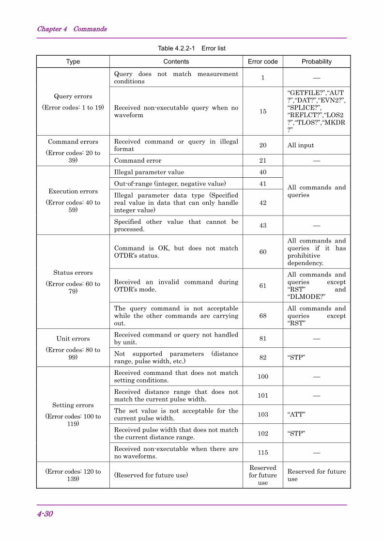
3.4.3 Error sequence The “ANS*” is sent from OTDR instead of “ANS0” or normal response, if the sending command or query is not accepted by OTDR. The “*” (asterisk) in the figure below shows Error code number. Table 4.2.2-1 Error list
PC(Controller)
OTDR
Command or Query(ex. “LD�2”, “ABC?”)
“ANS*” (ex. “ANS41”, “ANS20”)Command is not accepted.The number * following“ANS” string shows Errorcode.
*: Error code 1 to 255 (See Table 4.2.2-1 Error list)
Note: The SR-4731 data is described in this document, which includes the Anritsu original parameters. Those parameters are not specified in Telcordia SR-4731 Issue 1 February 2000, but Anritsu’s commands require these Anritsu original parameters. If the SR-4731 data do not contain the Anritsu original parameters, Anritsu’s commands can not handle the data. If the SR-4731 data including Anritsu original parameters are modified by user (ex.: edited by binary editor or another system), Anritsu commands can not support the data any more.
Table 4.1-4 System settings
No. Function Comman
d Query
20 Local date, time and time difference DATE2 DATE2?
21 IP, port, netmask and gateway NET NET?
22 Get system information ⎯ MINF?
23 Ethernet timeout setting CONNTM
CONNTM?
Table 4.1-5 Measurement result requests
No. Function Comman
d Query
24 Auto-measurement result ⎯ AUT?
25 Waveform data (LOG) ⎯ DAT?
26 Averaging result ⎯ AVE?
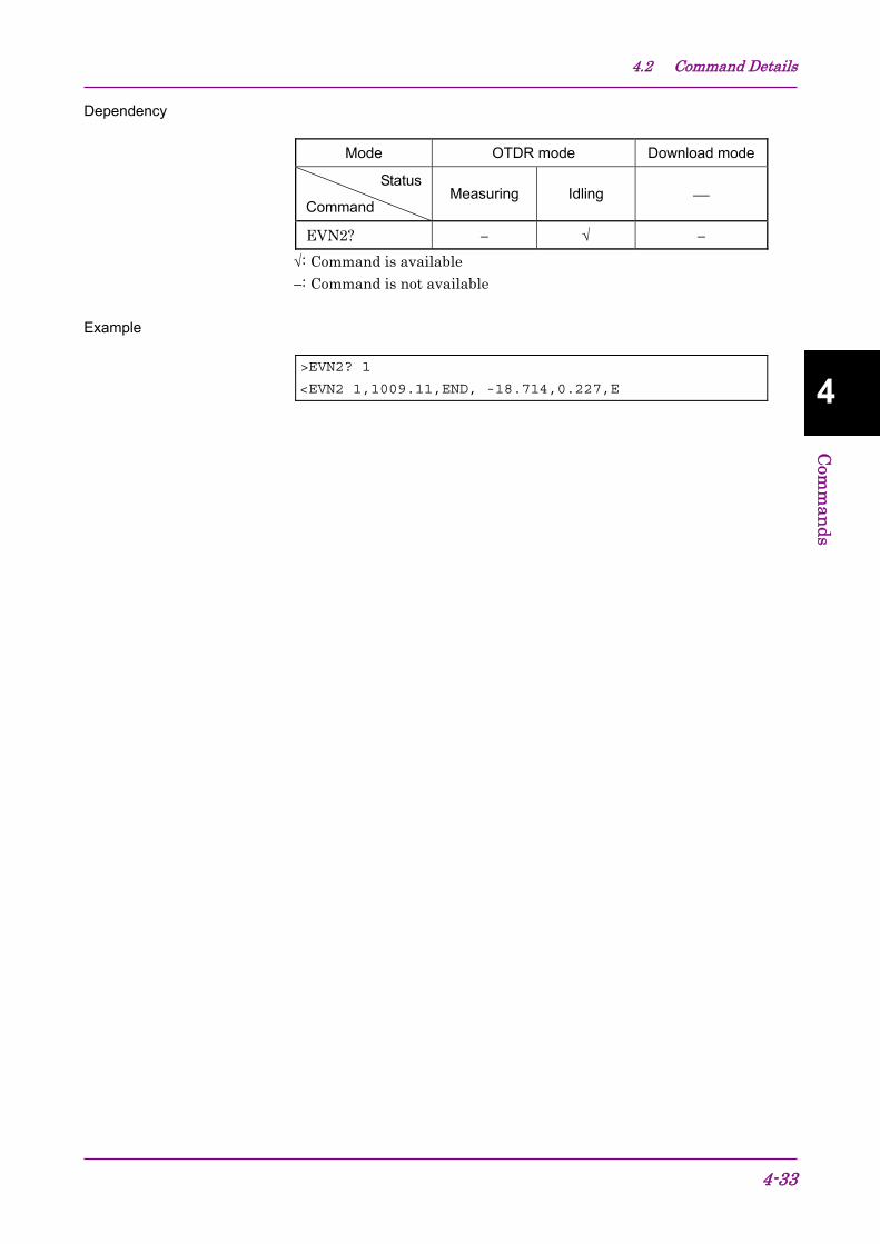
27 Event measurement result ⎯ EVN2?
28 Calculates the Splice loss ⎯ SPLICE?
29 Calculates the Reflectance ⎯ REFLCT?
30 Calculates the Loss ⎯ LOS2?
31 Calculates the Total loss ⎯ TLOS?
32 Relative distance OFS OFS?
33 Start point/end point for calculating the Total loss ⎯ MKDR?
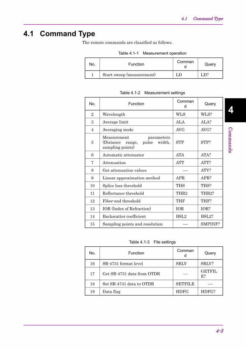
4.1 Command Type
4-5
4
Com
man
ds
Table 4.1-6 Status readout
No. Function Comman
d Query
34 Status ⎯ STATUS?
35 Error code ⎯ ERR?
36 Waveform data existence ⎯ WAV?
Table 4.1-7 Other settings
No. Function Comman
d Query
37 Initialize INI ⎯
38 Reset RST ⎯
39 Selftest ⎯ SLFTST?
40 Change Mode DLMODE
DLMODE?
41 Download the software DWNLD DWNLD?
Chapter 4 Commands
4-6
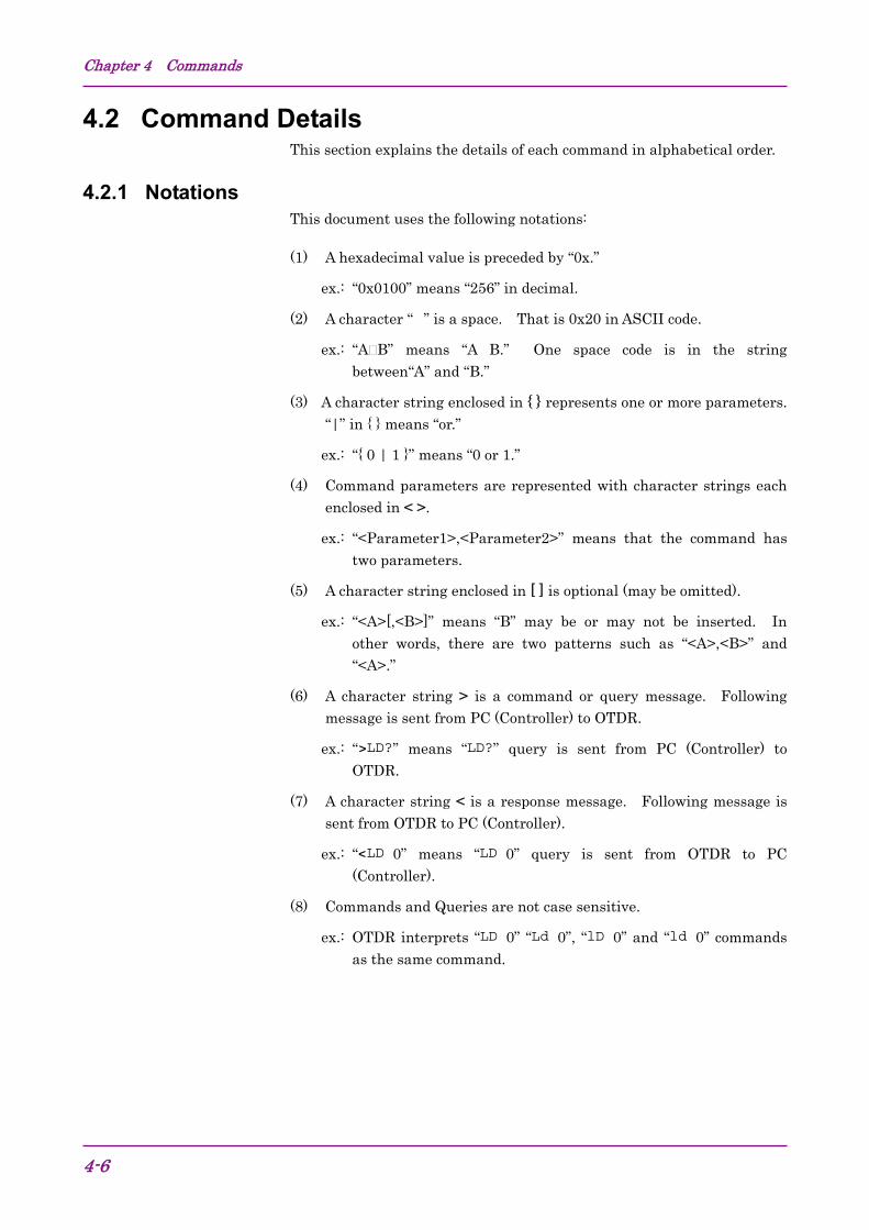
4.2 Command Details This section explains the details of each command in alphabetical order.
4.2.1 Notations This document uses the following notations:
(1) A hexadecimal value is preceded by “0x.”
ex.: “0x0100” means “256” in decimal.
(2) A character “�” is a space. That is 0x20 in ASCII code.
ex.: “A B” means “A B.” One space code is in the string between“A” and “B.”
(3) A character string enclosed in { } represents one or more parameters. “|” in { } means “or.”
ex.: “{ 0 | 1 }” means “0 or 1.”
(4) Command parameters are represented with character strings each enclosed in < >.
ex.: “<Parameter1>,<Parameter2>” means that the command has two parameters.
(5) A character string enclosed in [ ] is optional (may be omitted).
ex.: “<A>[,<B>]” means “B” may be or may not be inserted. In other words, there are two patterns such as “<A>,<B>” and “<A>.”
(6) A character string > is a command or query message. Following message is sent from PC (Controller) to OTDR.
ex.: “>LD?” means “LD?” query is sent from PC (Controller) to OTDR.
(7) A character string < is a response message. Following message is sent from OTDR to PC (Controller).
ex.: “<LD�0” means “LD�0” query is sent from OTDR to PC (Controller).
(8) Commands and Queries are not case sensitive.
ex.: OTDR interprets “LD�0” “Ld�0”, “lD�0” and “ld�0” commands as the same command.
4.2 Command Details
4-7
4
Com
man
ds
LD
Description Start measurement (sweep).
Command LD { 0 | 1 }
0: Stop measurement (sweep)
1: Start measurement (sweep)
Query LD?
Response LD { 0 | 1 }
0: Idling Status
1: Measuring Status
Dependency
Mode OTDR mode Download mode
Status
CommandMeasuring Idling ⎯
LD √ √ −LD? √ √ −
√: Command is available
−: Command is not available
Example
>LD 1
<ANS0
>LD?
<LD 1
Command
Query
Command or Query name
Response message
Dependency by StatusSee Table 4.2.1-1.
Sample messages
Prompt Direction
“>” PC to OTDR“<” OTDR to PC
Figure 4.2.1-1 Sample page of command details
Chapter 4 Commands
4-8
Table 4.2.1-1 OTDR mode and status
Mode Status Description
OTDR mode
Measuring
OTDR is measuring. Most query commands except for retrieving result are available. In contrast, most setting commands are not available in this status in order to avoid the incoherence conditions during the measurement.
Idling
OTDR is not measuring. Generally, most commands are available not only queries but also setting commands.
Download mode ⎯
To Download the software to OTDR. Commands not related to download are not available.
OTDR mode
Changes to Download modeand reset.(Send “DLMODE 1” and“RST” commands.)
Fail to download software.Software download is incomplete.
If the operator wants to quit Downloadmode before sending “DWNLD <Data>”command (In this case, “DWNLD?”command responds zero.), Mode can bechanged to OTDR mode by sending“DLMODE 0” and “RST” commands.
Download mode
Figure 4.2.1-2 State transition diagram between modes
4.2 Command Details
4-9
4
Com
man
ds
Measuring
Stops the measurement (“LD 0”),or finishes the measurement.Starts the measurement. (“LD 1”)
Idling
Figure 4.2.1-3 State transition diagram between status
Chapter 4 Commands
4-10
4.2.2 Commands
4.2 Command Details
4-11
4
Com
man
ds
ALA
Description Set averaging limit.
Command ALA�<Mode>,<Setting>
<Mode>
0: Number of times
1: Elapsed time
2: Auto setting
<Setting>
If Averaging mode is Auto, this variable is ignored. 1 to 9999: times (when Mode is Number of times)
1 to 9999: sec (when Mode is Elapsed time)
Query ALA?
Response ALA�<Mode>,<Setting(Number of times)>,<Setting(Elapsed time)>
<Setting(Number of times)>
1 to 9999: times
The response is “***” when the Mode is Auto setting and Setting is invalid.
<Setting(Elapsed time)>
1 to 9999: sec
The response is “***” when the Mode is Auto setting and Setting is invalid.
Dependency
Mode OTDR mode Download mode
Status
Command Measuring Idling ⎯
ALA − √ −
ALA? √ √ −
√: Command is available
−: Command is not available
Chapter 4 Commands
4-12
Example
>ALA�0,1 <ANS0
>ALA?
<ALA�0,1,2
>ALA�2,1 <ANS0
>ALA?
<ALA�1,***,***
4.2 Command Details
4-13
4
Com
man
ds
APR
Description Set linear approximation method. This setting value is used for “LOS2?” and “SPRICE?” commands.
Command APR�{ 0 | 1 }
0: 2PA (Two Point Approximation)
1: LSA (Least Square linear Approximation)
Query APR?
Response APR�{ 0 | 1 }
Dependency
Mode OTDR mode Download mode
Status
Command Measuring Idling ⎯
APR − √ −
APR? √ √ −
√: Command is available
−: Command is not available
Example
>APR�1 <ANS0
>APR?
<APR�1
Chapter 4 Commands
4-14
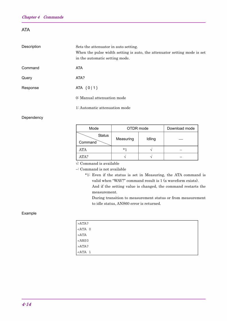
ATA
Description Sets the attenuator in auto setting. When the pulse width setting is auto, the attenuator setting mode is set in the automatic setting mode.
Command ATA
Query ATA?
Response ATA�{ 0 | 1 }
0: Manual attenuation mode
1: Automatic attenuation mode
Dependency
Mode OTDR mode Download mode
Status
Command Measuring Idling ⎯
ATA *1 √ −
ATA? √ √ −
√: Command is available
−: Command is not available *1: Even if the status is set in Measuring, the ATA command is
valid when “WAV?” command result is 1 (a waveform exists). And if the setting value is changed, the command restarts the measurement. During transition to measurement status or from measurement to idle status, ANS60 error is returned.
Example
>ATA?
<ATA�0 >ATA
<ANS0
>ATA?
<ATA�1
4.2 Command Details
4-15
4
Com
man
ds
ATT
Description Sets attenuation with attenuator.
Command ATT�<Attenuation>
Sets by the number of 3 decimal places in 1=1 dB unit. The set attenuation value can be obtained with the attenuator value selected in the “ AVT? “ command. When the pulse width setting is auto, the attenuation setting mode is also set to the automatic setting mode. When the pulse width setting is auto, ANS103 error is returned for the setting on this command.
Query ATT?
Response ATT� <Attenuation>
When attenuation setting is auto, the value is automatically determined. Moreover, until automatic determination, the attenuation value is kept to be indefinite value. In this case, “ATT�***” is returned as the response.
Dependency
Mode OTDR mode Download mode
Status
Command Measuring Idle ⎯
ATT *1 √ −
ATT? √ √ −
√: Command is available
−: Command is not available *1: Even if the status is set in Measuring, the ATT command is
valid when the “WAV?” command result is 1 (a waveform exists). And if the setting value is changed, the command restarts the measurement. During transition to measurement status or from measurement to idle status, ANS60 error is returned.
Example
>ATA�3 <ANS0
>ATT?
<ATT�3.000
Chapter 4 Commands
4-16
ATV?
Description Obtains the valid attenuation value for the specified pulse width.
Query ATV?�<Pulse Width>
<Pulse Width> is one of the values that can be set with the OTDR unit,
shown in 1= 1ns unit.
ex.: The one of the following values is selected.
(10, 30, 100, 300, 1000, 3000, 10000, 20000 ns )
Response ATV�<Attenuation>{,<Attenuation>}
<Attenuation>
1 = 1dB and the value is output to three decimal Returns by the number of 3 decimal places in 1=1 dB unit. All available attenuation values are output for the specified pulse width.
Dependency
Mode OTDR mode Download mode
Status
Command Measuring Idle ⎯
ATV? √ √ −
√: Command is available
−: Command is not available Example
>ATV?�10 <ATV�0.0003,3.000,8.000,13.000,18.000
4.2 Command Details
4-17
4
Com
man
ds
AUT?
Description Read auto-measurement results.
Query AUT?
Response AUT�<Total number of the events>,<Fiber length>,<Total loss>,<Total return
loss>
<Total number of the events>
0 to 99
<Fiber length>
Distance unit, IOR correction distance data. The numeric value in meters is rounded to the three decimal point. “***” is output if measurement is impossible.
<Total loss>
The unit is dB. The value is output with the third decimal place. “***” is output if measurement is impossible.
<Total return loss>
The first byte indicates the status of the reflectance as the following table:
1st byte Total return loss
“<” The value is saturated.
“�” (space) The value is not saturated.
The unit is dB. 1 = 1 dB and the value is output with three decimal places. “***” is output if measurement is impossible.
Dependency
Mode OTDR mode Download mode
Status
Command Measuring Idling ⎯
AUT? − √ −
√: Command is available
−: Command is not available
Example
>AUT?
<AUT�1,1009.11,0.247,<19.848
Chapter 4 Commands
4-18
AVE?
Description Read current averaging count and time.
Query AVE?
Response AVE�<Averaging mode>,<Count value (Count)>,<Count value (Time)>
<Averaging mode>
0: Manual (“Number of times” or “Elapsed time”)
1: Auto setting
<Count value (Count)>
Current averaging count in the number of times unit
<Count value (Time)>
Current averaging times in second unit
Dependency
Mode OTDR mode Download mode
Status
Command Measuring Idling ⎯
AVE? √ √ −
√: Command is available
−: Command is not available
Example
>AVE?
<AVE�1,0,0
4.2 Command Details
4-19
4
Com
man
ds
AVG
Description Sets the Averaging mode (ON/OFF). When Averaging mode is ON, the value set with the ALA command is valid.
Command AVG�{0|1}
0: Averaging OFF (Real time trace). 1: Averaging ON.
Query AVG?
Response AVG� {0|1}
Dependency
Mode OTDR mode Download mode
Status
Command Measuring Idle ⎯
AVG − √ −
AVE? √ √ −
√: Command is available
−: Command is not available
Example
>AVG�0 <ANS0
>AVG?
<AVG�0
Chapter 4 Commands
4-20
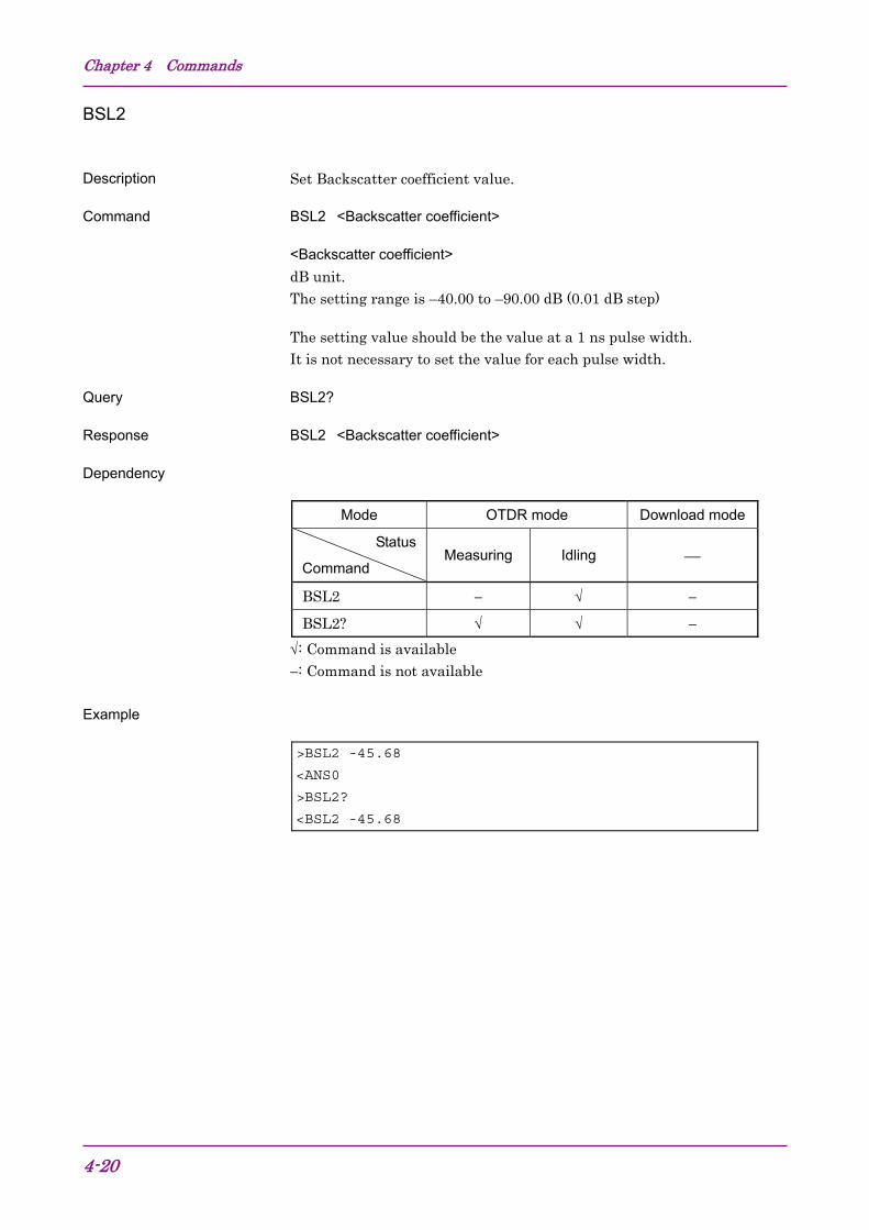
BSL2
Description Set Backscatter coefficient value.
Command BSL2�<Backscatter coefficient>
<Backscatter coefficient>
dB unit. The setting range is –40.00 to –90.00 dB (0.01 dB step)
The setting value should be the value at a 1 ns pulse width. It is not necessary to set the value for each pulse width.
Query BSL2?
Response BSL2�<Backscatter coefficient>
Dependency
Mode OTDR mode Download mode
Status
Command Measuring Idling ⎯
BSL2 − √ −
BSL2? √ √ −
√: Command is available
−: Command is not available
Example
>BSL2�-45.68 <ANS0
>BSL2?
<BSL2�-45.68
4.2 Command Details
4-21
4
Com
man
ds
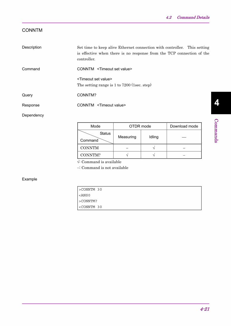
CONNTM
Description Set time to keep alive Ethernet connection with controller. This setting is effective when there is no response from the TCP connection of the controller.
Command CONNTM�<Timeout set value>
<Timeout set value>
The setting range is 1 to 7200 (1sec. step)
Query CONNTM?
Response CONNTM�<Timeout value>
Dependency
Mode OTDR mode Download mode
Status
Command Measuring Idling ⎯
CONNTM − √ −
CONNTM? √ √ −
√: Command is available
−: Command is not available
Example
>CONNTM�30 <ANS0
>CONNTM?
<CONNTM�30
Chapter 4 Commands
4-22
DAT?
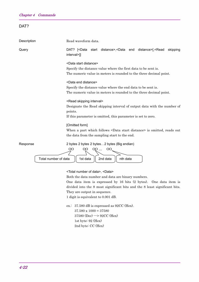
Description Read waveform data.
Query DAT?�[<Data start distance>,<Data end distance>[,<Read skipping
interval>]]
<Data start distance>
Specify the distance value where the first data to be sent is. The numeric value in meters is rounded to the three decimal point.
<Data end distance>
Specify the distance value where the end data to be sent is. The numeric value in meters is rounded to the three decimal point.
<Read skipping interval>
Designate the Read skipping interval of output data with the number of points. If this parameter is omitted, this parameter is set to zero.
[Omitted form]
When a part which follows <Data start distance> is omitted, reads out the data from the sampling start to the end.
Both the data number and data are binary numbers. One data item is expressed by 16 bits (2 bytes). One data item is divided into the 8 most significant bits and the 8 least significant bits. They are output in sequence. 1 digit is equivalent to 0.001 dB.
ex.: 37.580 dB is expressed as 92CC (Hex). 37.580 x 1000 = 37580 37580 (Dec) ---> 92CC (Hex) 1st byte: 92 (Hex) 2nd byte: CC (Hex)
Total number of data 1st data nth data 2nd data
4.2 Command Details
4-23
4
Com
man
ds
Dependency
Mode OTDR mode Download mode
Status
Command Measuring Idling ⎯
DAT? √ √ −
√: Command is available
−: Command is not available
Example
>DAT?
<00011234 (Binary data)
Chapter 4 Commands
4-24
DATE2
Description Set local date and time, then assign the time difference from UTC (Universal Coordinated Time) to local time.
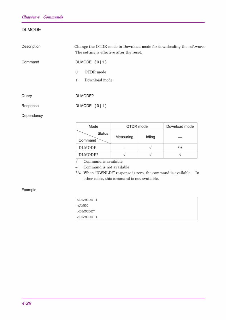
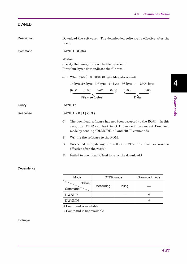
0: The download software has not been accepted to the ROM. In this case, the OTDR can back to OTDR mode from current Download mode by sending “DLMODE�0” and “RST” commands.
1: Writing the software to the ROM.
2: Succeeded of updating the software. (The download software is effective after the reset.)
3: Failed to download. (Need to retry the download.)
Dependency
Mode OTDR mode Download mode
Status
Command Measuring Idling ⎯
DWNLD − − √
DWNLD? − − √
√: Command is available
−: Command is not available
Example
File size (bytes) Data
Chapter 4 Commands
4-28
>DWNLD�00000001FF (Binary data) <ANS0
>DWNLD?
<DWNLD�2
4.2 Command Details
4-29
4
Com
man
ds
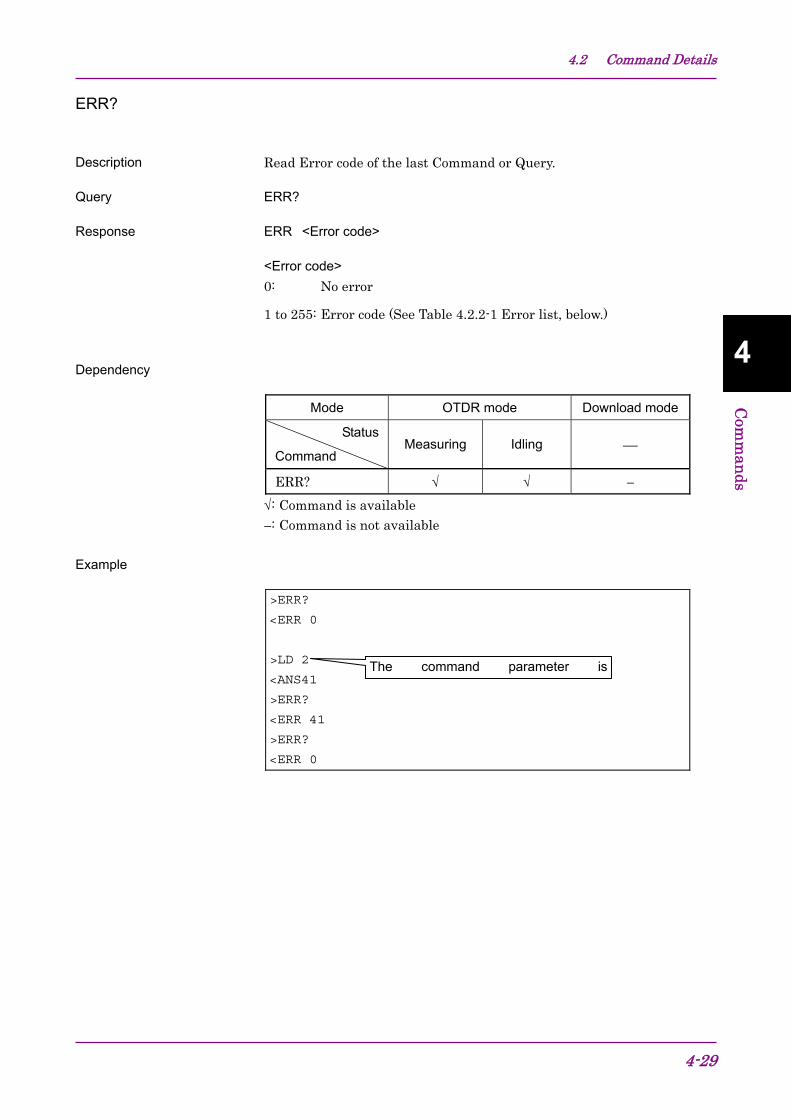
ERR?
Description Read Error code of the last Command or Query.
Query ERR?
Response ERR�<Error code>
<Error code>
0: No error
1 to 255: Error code (See Table 4.2.2-1 Error list, below.)
Description Input the data flag of the header. This value is corresponded to CDF (Current Data Flag) in SR-4731.
Command HDFG�{ 0 | 1 | 2 }
0: BC (Installation)
1: RC (Repair)
2: OT (Other)
Query HDFG?
Response HDFG�{ 0 | 1 | 2 }
Dependency
Mode OTDR mode Download mode
Status
Command Measuring Idling ⎯
HDFG − √ −
HDFG? √ √ −
√: Command is available
−: Command is not available
Example
>HDFG�0 <ANS0
>HDFG?
<HDFG�0
Chapter 4 Commands
4-36
INI
Description Recall the parameter information, and set OTDR condition to the power-on. The network parameters (ie. IP, port, netmask and gateway) are not initialized.
Command INI
Dependency
Mode OTDR mode Download mode
Status
Command Measuring Idling ⎯
INI √ √ −
√: Command is available
−: Command is not available
Example
>INI
<ANS0
4.2 Command Details
4-37
4
Com
man
ds
IOR
Description Set IOR (Index of Refraction) limit.
Command IOR�<IOR value>
<IOR value>
Valid up to six decimal places from 1.400000 to 1.699999
Query IOR?
Response IOR�<IOR value>
Dependency
Mode OTDR mode Download mode
Status
Command Measuring Idling ⎯
IOR − √ −
IOR? √ √ −
√: Command is available
−: Command is not available
Example
>IOR�1.456789 <ANS0
>IOR?
<IOR�1.456789
Chapter 4 Commands
4-38
LD
Description Start measurement (sweep).
Command LD�{ 0 | 1 }
0: Stop measurement (sweep)
1: Start measurement (sweep)
Query LD?
Response LD�{ 0 | 1 }
0: Idling Status
1: Measuring Status
Dependency
Mode OTDR mode Download mode
Status
Command Measuring Idling ⎯
LD √ √ −
LD? √ √ −
√: Command is available
−: Command is not available
Example
>LD�1 <ANS0
>LD?
<LD�1
4.2 Command Details
4-39
4
Com
man
ds
LOS2?
Description Calculate the loss between X1 and X2.
Query LOS2?�<X1 location>,<X2 location>
<X1 location>
m (meter) unit Location of the X1 marker. This value is rounded off to the sampling location internally.
<X2 location>
m (meter) unit Location of the X2 marker. This value is rounded off to the sampling location internally.
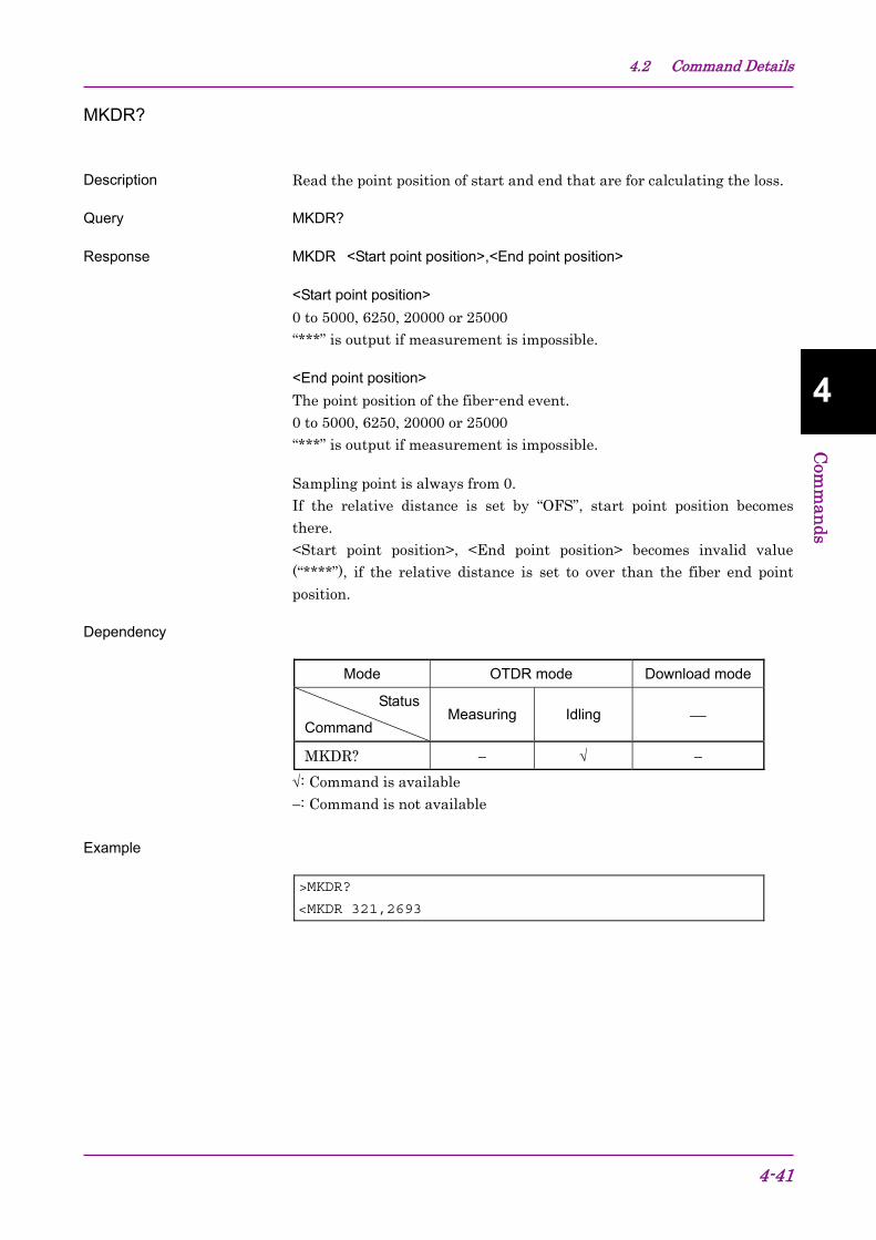
Description Read the point position of start and end that are for calculating the loss.
Query MKDR?
Response MKDR�<Start point position>,<End point position>
<Start point position>
0 to 5000, 6250, 20000 or 25000 “***” is output if measurement is impossible.
<End point position>
The point position of the fiber-end event. 0 to 5000, 6250, 20000 or 25000 “***” is output if measurement is impossible.
Sampling point is always from 0. If the relative distance is set by “OFS”, start point position becomes there. <Start point position>, <End point position> becomes invalid value (“****”), if the relative distance is set to over than the fiber end point position.
Dependency
Mode OTDR mode Download mode
Status
Command Measuring Idling ⎯
MKDR? − √ −
√: Command is available
−: Command is not available
Example
>MKDR?
<MKDR 321,2693
Chapter 4 Commands
4-42
NET
Description Set network parameters. The setting parameters are effective after the reset.
Description Set the relative distance. This value is corresponded to UOD (User Offset Distance) in SR-4731.
Command OFS�<Relative distance>
<Relative distance>
Relative distance This value is rounded off to the third decimal point in m (meter) unit.
Query OFS?
Response OFS�<Relative distance>
Dependency
Mode OTDR mode Download mode
Status
Command Measuring Idling ⎯
OFS − √ −
OFS? √ √ −
√: Command is available
−: Command is not available
Example
>OFS�34.50 <ANS0
>OFS?
<OFS�34.50
Chapter 4 Commands
4-44
REFLCT?
Description Calculate the reflectance.
Query REFLCT?�<Event location>,<Peak location>
<Event location>
m (meter) unit Event location is corresponded to EPT (Event Propagation Time) in SR-4731. This value is rounded off to the sampling location internally.
<Peak location>
m (meter) unit Location of the Peak marker. The peak marker corresponds to ML5 in SR-4731. This value is rounded off to the sampling location internally.
Description Hardware reset (restart) of the OTDR Module. After the reset, OTDR Module does not send “ANS0” message. TCP/IP connection is dis-connected, if TCP/IP port is in use. After rebooting (it takes more than 15 seconds), re-connection is required for TCP/IP port.
Command RST
Dependency
Mode OTDR mode Download mode
Status
Command Measuring Idling ⎯
RST √ √ √
√: Command is available
−: Command is not available
Example
>RST
No response (No message is sent from OTDR.) See Figure 3.4.1-2.
4.2 Command Details
4-47
4
Com
man
ds
SETFILE
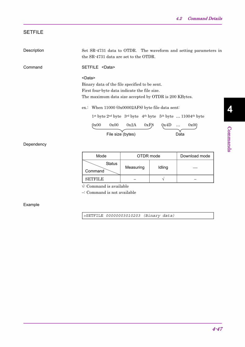
Description Set SR-4731 data to OTDR. The waveform and setting parameters in the SR-4731 data are set to the OTDR.
Command SETFILE�<Data>
<Data>
Binary data of the file specified to be sent. First four-byte data indicate the file size. The maximum data size accepted by OTDR is 200 KBytes.
Description Get the selftest results. The OTDR always checks itself. If the OTDR detects any troubles in itself, the OTDR notifies it by sending the error message “Ans 255” to the response of the 1st command just after the trouble detected.
Query SLFTST?
Response SLFTST�<Selftest result>
<Selftest result>
0: OK
1: Slight trouble. The OTDR operates normally.
2 to 65535: NG
Dependency
Mode OTDR mode Download mode
Status
Command Measuring Idling ⎯
SLFTST? − √ √
√: Command is available
−: Command is not available
Example
(When no trouble detected.)
>SLFTST?
<SLFTST�0
(When trouble detected.)
>LD�1 <ANS0
(A slight trouble here detected.)
>STATUS?
<STATUS�1 (A trouble here detected.)
>STATUS? (1st command after a trouble detected.)
<ANS255
>SLFTST?
<SLFTST�16
4.2 Command Details
4-49
4
Com
man
ds
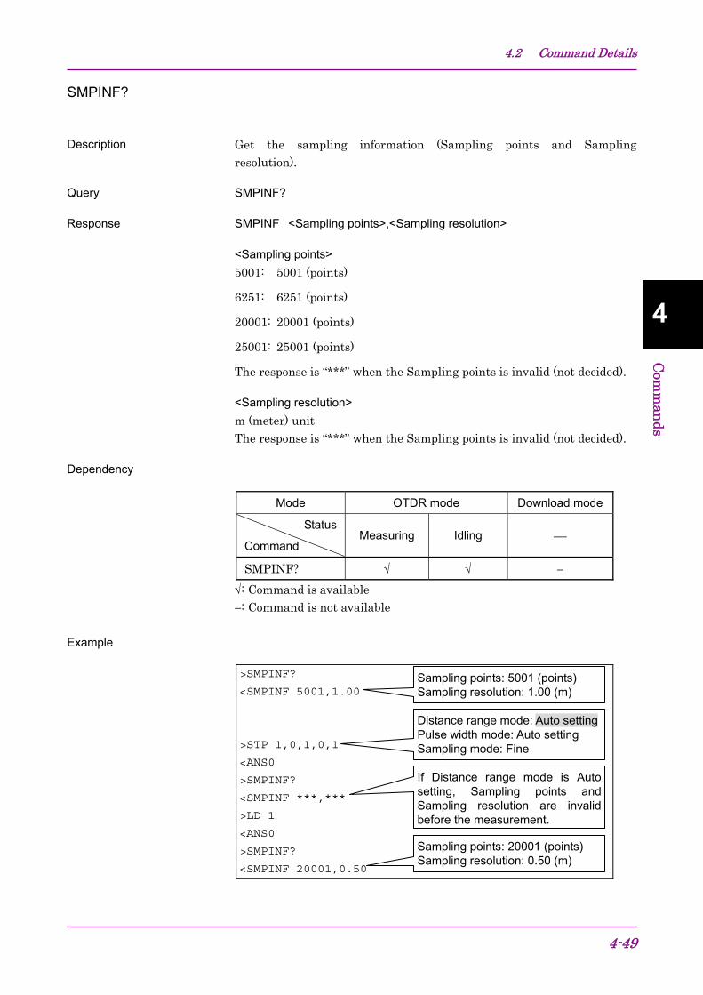
SMPINF?
Description Get the sampling information (Sampling points and Sampling resolution).
m (meter) unit Event location of the nearest sampling position
<Sampled X1 location>
m (meter) unit X1 location of the nearest sampling position
<Sampled X2 location>
m (meter) unit X2 location of the nearest sampling position
<Sampled X3 location>
m (meter) unit X3 location of the nearest sampling position
<Sampled X4 location>
m (meter) unit X4 location of the nearest sampling position
<Splice loss>
The unit is dB. 1 = 1 dB and the value is output with three decimal places. “***” is output when the value of Splice loss is under –99.999 (dB) or over 99.999 (dB).
OTDR operations as follows: Measurement (Figure 5.1.2-1) Network settings (Figure 5.1.3-1) Change to Download mode (Figure 5.1.4-1)
A2
Download mode
Software download (Figure 5.1.4-2)
: Command or Query : Procedure
Figure 5.1.1-1 Sequence Overview
5.1 Sample Sequences
5-3
5
Sample Sequences
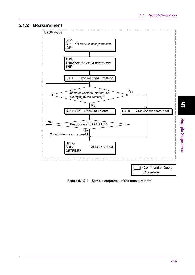
5.1.2 Measurement OTDR mode
No
THSTHR2 Set threshold parameters.THF
Operator wants to interrupt theAveraging (Measurement) ?
Yes
: Command or Query: Procedure
LD�1 Start the measurement.
STPALA Set measurement parameters.IOR
STATUS? Check the status.
Response = “STATUS�1”?
HDFGSRLV Get SR-4731 file.GETFILE?
No(Finish the measurement.)
LD�0 Stop the measurement.
Yes
Figure 5.1.2-1 Sample sequence of the measurement
Chapter 5 Sample Sequences
5-4
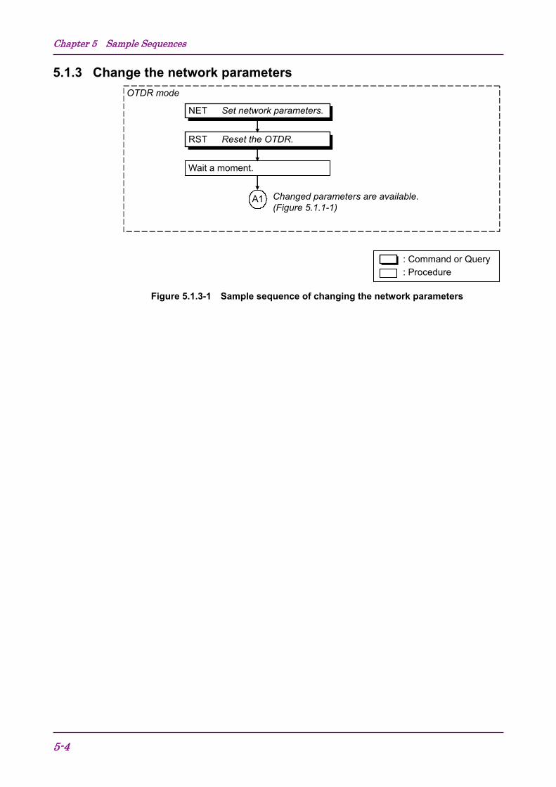
5.1.3 Change the network parameters OTDR mode
Wait a moment.
RST Reset the OTDR.
NET Set network parameters.
Changed parameters are available. (Figure 5.1.1-1)
A1
: Command or Query : Procedure
Figure 5.1.3-1 Sample sequence of changing the network parameters
5.1 Sample Sequences
5-5
5
Sample Sequences
5.1.4 Software download When operator want to download the software to OTDR, the following two steps are needed, if the current mode is OTDR mode. If the current mode is Download mode, only Step 2 is needed.
Figure 5.1.4-1 Sample sequence of changing the Mode
Chapter 5 Sample Sequences
5-6.
Download mode
No
Operator wants to change to OTDR mode?
Yes
: Command or Query : Procedure
DWNLD? Check download status.
RST Reset the OTDR.
Response = “DWNLD�2”?
Yes (Succeeded the download.)
RST Reset the OTDR. DWNLD Download the software.
Response = “DWNLD�1”?
Wait a moment.
Downloaded software is available. (Figure 5.1.1-1)
A1
Wait a moment.
Quit Download mode. (Figure 5.1.1-1)
A1
No
DWNLD? Check download status.
Response = “DWNLD�0”?
Yes
No
Yes
Software download
No
Figure 5.1.4-2 Sample sequence of software download
6-1
6
Performance Test and C
alibration Chapter 6 Performance Test and Calibration
This section explains how to check the performance of the OTDR Module and how to calibrate the measured values.
Contact Anritsu Corporation or your nearest service representative if the performance test described in this section reveals that the system does not conform to specifications.
Provide the following data in advance when requesting repairs.
(1) Model name, and instrument serial number affixed at the bottom of the machine.
(2) Failure details (3) Name and telephone number of the person in charge whom Anritsu
can contact for the detail of the failure or report the completion of repair.
6.1 Performance Test ......................................................... 6-2
6.2 Calibration ................................................................... 6-11 6.3 Performance Test Result Record Form ...................... 6-12
WARNING NEVER look directry into the optical connector of the OTDR or the end of the optical cable connected to the OTDR as the laser light can injure your eye. Procedures other than those specified herein may result in hazardous radiation exposure.
CAUTION The OTDR Module outputs high-power optical pulses. Disconnect the communication equipments from the optical fibers before a measurement, or the optical sensor of the equipment may be broken.
Chapter 6 Performance Test and Calibration
6-2
6.1 Performance Test The following 5 items should be tested to check the performance of the OTDR.
1. Wavelength 2. Pulse width 3. Dynamic range 4. Distance measurement accuracy 5. Loss measurement accuracy (Linearity) Specification values of test items The following specification values are guaranteed at a temperature of 25±5°C.
SM Optical fiber (75 km) √ SM Optical fiber (2 km) √ SM Optical fiber (2 m) √ √ Optical fiber coupler (3 dB) √ 1310 nm cut optical filter Insertion loss: ≥40 dB (1310 ±25 nm) ≤3 dB (1550 nm)
√
(Only for option 01)
Chapter 6 Performance Test and Calibration
6-4
6.1.1 Wavelength This test measures the center wavelength of the laser output light and checks that it meets the specification.
Setup Connect the OTDR Module as shown in the figure below.
OTDRModuleController
Optical spectrumanalyzer
Optical fiber (2 m)
Test procedure (1) Set the distance range to 50 km, pulse width to 1000 ns and average
limit to 300 sec with the OTDR Module. (2) Start the OTDR measurement and input the laser light into the
optical spectrum analyzer, then adjust its measurement level and wavelength resolution. Use variable optical attenuator if optical spectrum analyzer is saturated because of the high input power of the OTDR.
(3) Select the RMS method on the optical spectrum analyzer. (4) Check that the measurement result is within specification values. Related command ALA, STP, LD
6.1 Performance Test
6-5
6
Performance Test and C
alibration
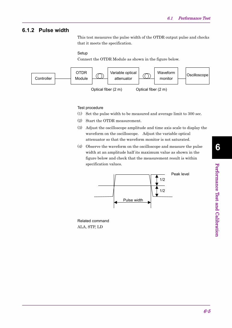
6.1.2 Pulse width This test measures the pulse width of the OTDR output pulse and checks that it meets the specification.
Setup Connect the OTDR Module as shown in the figure below.
OTDRModuleController
Variable opticalattenuator
Optical fiber (2 m)
Waveformmonitor
Oscilloscope
Optical fiber (2 m)
Test procedure (1) Set the pulse width to be measured and average limit to 300 sec. (2) Start the OTDR measurement. (3) Adjust the oscilloscope amplitude and time axis scale to display the
waveform on the oscilloscope. Adjust the variable optical attenuator so that the waveform monitor is not saturated.
(4) Observe the waveform on the oscilloscope and measure the pulse width at an amplitude half its maximum value as shown in the figure below and check that the measurement result is within specification values.
Pulse width
1/2
1/2
Peak level
Related command ALA, STP, LD
Chapter 6 Performance Test and Calibration
6-6
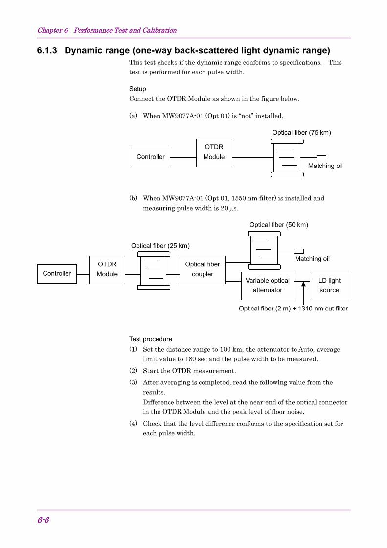
6.1.3 Dynamic range (one-way back-scattered light dynamic range) This test checks if the dynamic range conforms to specifications. This test is performed for each pulse width.
Setup Connect the OTDR Module as shown in the figure below.
(a) When MW9077A-01 (Opt 01) is “not” installed.
Optical fiber (75 km)
OTDRModuleController
Matching oil
(b) When MW9077A-01 (Opt 01, 1550 nm filter) is installed and measuring pulse width is 20 µs.
OTDRModuleController
Variable opticalattenuator
Optical fiber (2 m) + 1310 nm cut filter
Optical fibercoupler
Optical fiber (50 km)
LD lightsource
Matching oil
Optical fiber (25 km)
Test procedure (1) Set the distance range to 100 km, the attenuator to Auto, average
limit value to 180 sec and the pulse width to be measured. (2) Start the OTDR measurement. (3) After averaging is completed, read the following value from the
results. Difference between the level at the near-end of the optical connector in the OTDR Module and the peak level of floor noise.
(4) Check that the level difference conforms to the specification set for each pulse width.
6.1 Performance Test
6-7
6
Performance Test and C
alibration
(5) When MW9077A-01 is installed and measuring with pulse width 20 µs, input 1550 nm CW-light by use of the optical fiber coupler (see figure above) and check the level difference conforms to the specification. Adjust the input power of the LD light source to be −20 dBm. When calculating the difference, be sure to consider the loss of the optical fiber coupler.
Related command ALA, STP, LD, DAT?
Chapter 6 Performance Test and Calibration
6-8
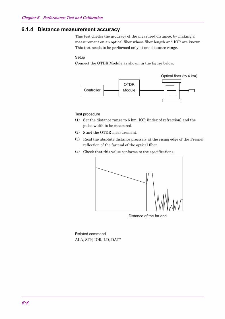
6.1.4 Distance measurement accuracy This test checks the accuracy of the measured distance, by making a measurement on an optical fiber whose fiber length and IOR are known. This test needs to be performed only at one distance range.
Setup Connect the OTDR Module as shown in the figure below.
Optical fiber (to 4 km)
OTDRModuleController
Test procedure (1) Set the distance range to 5 km, IOR (index of refraction) and the
pulse width to be measured. (2) Start the OTDR measurement. (3) Read the absolute distance precisely at the rising edge of the Fresnel
reflection of the far-end of the optical fiber. (4) Check that this value conforms to the specifications.
Distance of the far end
Related command ALA, STP, IOR, LD, DAT?
6.1 Performance Test
6-9
6
Performance Test and C
alibration
6.1.5 Loss measurement accuracy (Linearity) This test checks the accuracy of the loss measurement. There are 2 procedures for test.
Setup 1. Connect the OTDR Module as shown in the figure below. This case is for users who cannot prepare the fibers which are calibrated for the linearity.
Optical fiber (25 km)
OTDRModuleController
ATT-A ATT-B
4% Fresnel reflection
Variable optical attenuator
3 m max
Test procedure (1) Set the pulse width to 100 ns. (2) Start the OTDR measurement. (3) Set ATT-B to 0 dB, and then adjust ATT-A so that the far-end
Fresnel reflection peak is slightly below the saturation level (within 0.2 dB).
(4) Read the level of the Fresnel reflection and define this value as PL0. (5) Set ATT-B to 2 dB and measure the level of Fresnel reflection.
Define this value as PH0. (6) Return ATT-B to 0 dB and increase the attenuation of ATT-A by 1 dB
and measure the level of Fresnel reflection. Define this value as PL1.
(7) Set ATT-B to 2 dB and measure the level of Fresnel reflection. Define this value as PH1.
(8) Increase the attenuation of ATT-A by 1 dB step up to 15 dB to measure PLi and PHi at each step.
(9) Obtain the loss measurement accuracy at each ATT-A setting using the following formula and check that they conforms to the specifications. Loss measurement accuracy = {(PLi − PHi) −∆A}/∆A where, ∆A is the defference between ATT-B settings at 0 dB and 2 dB (calibrated in advance).
Related command ALA, STP, LD, DAT?
Chapter 6 Performance Test and Calibration
6-10
Setup 2. Connect the OTDR Module as shown in the figure below. This case is for users who can prepare the fibers which are calibrated for the linearity.
Optical fiber (40 km)
OTDRModuleController
Test procedure (1) Set the pulse width to 100 ns and the wavelength to 1.31 µm. (2) Start the OTDR measurement. (3) Measure the loss (Lx) of the fiber by 3 km through 30 km, and
calculate the average (Lave_m) of them. When calculating the average, be sure to calculate for each different fiber.
(4) Calculate the difference (Ldiff_n) between Lx and Lave_m (Lx -Lave_m). (5) Check that the difference (Ldiff_n) is smaller than ±0.1 dB. ex. When 2 fibers (20 km×2) are connected.
6.2 Calibration Only the back-scattered level can be calibrated using the OTDR. This calibration is needed only when user wants to fit the return loss to the known value.
Setup Prepare an optical connector with a known return loss R0 dB and connect the OTDR as shown in the figure below.
Optical fiber
OTDRModuleController
Optical fiber
Optical connector of known return loss
Calibration procedure (1) Set backscatter level to 0 dB, pulse width to 100 ns. (2) Start the OTDR measurement. (3) After the measurement is completed, set the linear approximation
method to LSA and measure the return loss of the known connector. Define this value as R1 dB.
(4) Obtain the difference between R1 and R0 (R1−R0) and set this value as backscatter level.
(5) Calibration is completed when the measured return loss at the connector becomes equal to R0.
Related command ALA, STP, APR, BSL2, LD, EVN2?, DAT?
Chapter 6 Performance Test and Calibration
6-12
6.3 Performance Test Result Record Form Test location: Report No.: Date: Tested by: Unit name: Serial No.: Ambient temperature: °C Relative humidity: % Remarks:
6.3 Performance Test Result Record Form
6-13
6
Performance Test and C
alibration
MW9077A/A1 OTDR Module
Test item Specification Result Remarks Wavelength 1310 nm ±25 nm Pulse width: 1
±1 m ±3 × 10⁻⁵ × measurement distance ±sampling space (excluding uncertainty caused by fiber IOR)
Loss measurement accuracy
±0.05 dB/dB or ±0.1 dB (whichever is greater)
Chapter 6 Performance Test and Calibration
6-14.
7-1
7
Maintenance
Chapter 7 Maintenance This section explains how to clean the OTDR Module to maintain its performance, as well as the suggestions for storage and transportation.
7.1 Optical Connector & Optical Adapter Cleaning Cleaning built-in ferrule end-face Use adapter cleaner supplied for this module to clean the built-in optical I/O connector ferrule. Clean the ferrule periodically.
Cleaning optical adapter Use adapter cleaner supplied for this module to clean the optical adapter for connection to the fiber-optic cable. An example of the FC adapter is described below. Follow similar methods and steps for cleaning other adapters. In addition, clean the adapter which was removed to clean the built-in ferrule end-face using the following steps.
Insert the adapter cleaner to the split sleeve interior of the adapter then move it back and forth while rotating it in one direction.
Note: Check the ferrule radius. Use only a φ1.25 mm or φ2.5 mm dedicated adapter cleaner.
7.1 Optical Connector & Optical Adapter Cleaning
7-3
7
Maintenance
Cleaning the ferrule end-face of the fiber-optic cable Use ferrule cleaner supplied for this module to clean the ferrule of the cable end. An example of the FC connector is described below. Follow similar methods and steps for cleaning other connectors.
(1) Lift the ferrule cleaner lever to access the cleaning face.
(2) Keep the lever in this position then press down the ferrule end-face of the optical connector on the cleaning face and rub in one direction.
Notes on cleaning (1) Do not clean with used adapter cleaner. (2) Do not finish clean with a cotton swab as cotton fibers may adhere to
the surface. (3) Make sure to cap adapters that are not in use.
WARNING Ensure that no light is emitted when cleaning or checking the ferrule end-face.
CAUTION Performance may be degraded if used when dust or dirt is adhering to the ferrule end-face. In addition, the connected fiber-optic cable & ferrule end-face of this module may burn out if high-output light is used in this state. Clean the connected fiber-optic cable and ferrule end-face of this module before performing measurements.
Chapter 7 Maintenance
7-4
7.2 Suggestions for Storage The following points should be kept in mind if the module is not to be used for a long period of time.
(1) Store the module after removing the dust on it. (2) Do not store the module at a place where the temperature in greater
than 60°C or less than –20°C, or where the humidity is greater than 85%.
(3) Do not store the module in a place where it is exposed to direct sunlight or dust.
(4) Do not store the module in a place where there is a possibility of condensation or erosion by active gas.
(5) Do not store the module in the place where there is a possibility of oxidization or strong vibrations.
(6) It is recommended that the battery pack is removed from the module.
Recommended conditions for storage It is recommended that the module be stored in a place which satisfies the above requirements and the conditions below.
(1) Temperature: from 5 to 30°C (2) Humidity: from 40 to 75% (3) Where the changes in temperature and humidity within one day are
not large.
7.3 Method of Transportation
7-5
7
Maintenance
7.3 Method of Transportation To transport this module, repack it using the packing materials used at the time of purchasing. If the packing materials have not been kept, repack it as indicated in step (3) and (4) below. The repackaging procedure is as follows.
(1) Clean the module surface with a dry cloth. (2) Check that the screws are tight. (3) Cover the projections and portions which can be easily deformed,
and wrap this module in a polyester sheet. (4) Place the wrapped module into a corrugated paper box and seal the
box with an adhesive tape. Then, insert this into a wooden box suitable for long-distance transportation.
Chapter 7 Maintenance
7-6.
7.4 Disposal Follow the instructions of your local waste disposal office when disposing of theOTDR Module.
A-1
Appendix
Appendix A
Appendix A Specifications
(1) OTDR Module (MW9077A/A1)
Items Specifications Remarks Model name/Unit name MW9077A/A1 OTDR Module Wavelength 1310 ±25 nm (MW9077A)
1550 ±25 nm (MW9077A1) at 25°C Pulse width: 1 µs
Fiber under test 10/125 µm SMF (ITU-T G.652) Optical connector LC: Option 33
Automatic measurement Measurement items Threshold value
Splice loss Return loss Reflectance Far end of fiber
Detected events Auto setting
Total loss. Distance, splice loss, return loss and reflectance of each event (Table form). 0.01 to 9.99 dB (0.01 dB step) 20 to 60 dB (0.1 dB step) −14 to −70 dB (0.1 dB step) 1 to 99 dB (1 dB step) Up to 99 Distance range, pulse width and number (or time) of averaging.
*1
Manual measurement Measurement items Real time sweeping
Loss and distance between any two points, splice loss, return loss or reflectance. Sweeping time: 0.1 to 0.2 seconds or less.
*2
Distance range 5/10/25/50/100/200/250/400 km IOR=1.500000 Maximum output power ≤+20 dBm Pulse width 10 ns ±30%
Items Specifications Remarks Dynamic range MW9077A
≥41 dB ≥39 dB MW9077A1 ≥40 dB ≥38 dB
at 25°C, 20 µs at −5 to +55°C (SNR=1) at 25°C, 20 µs at −5 to +55°C (SNR=1)
Deadzone (Back-scattered light)
≤20 m Pulse width: 10 ns
Deadzone (Fresnel reflection)
≤5 m Pulse width: 10 ns Return loss: ≤35 dB
Marker resolution 0.05 to 800 m IOR=1.500000 Sampling resolution 0.05 to 80 m IOR=1.500000 Sampling points Normal mode: 5001, 6251
Fine mode: 20001, 25001 *3
IOR setting 1.400000 to 1.699999 (0.000001 step) Distance measurement accuracy
±1 m ±3 × 10⁻⁵ × measurement distance ±sampling space (excluding uncertainty caused by fiber IOR)
Loss measurement accuracy (Linearity)
±0.05 dB/dB or ±0.1 dB (whichever is greater)
Return loss measurement accuracy
±2 dB
Optical filter Includes 1500 to 1625 nm cut optical filter. Operates normally when there is an optical power inputs under −20 dBm.
Option 01: only for MW9077A
Damp proofing General specifications and environmental conditions remain the same as MW9077A/A1.
Option 03
Other functions Relative distance setting (zero cursor set). Calender and clock (no battery backup). Distance unit setting (fixed to m).
Laser safety specification 21CFR Class I, IEC 60825-1:2007 Class 1 Power supply +12 Vdc ±1 V, 1.5 A max Interface Serial interface
RS-232C: 115.2 kbps max Ethernet 10 Mbps
Size 200×130×25 mm Environmental condition Operating temperature Humidity Storage temperature Vibration
−5 to +55°C, ≤95% (no condensation) −40 to +70°C Conforms to MIL-T-28800E Class 3
EMC Emission EN 61326-1 (Class A) Immunity EN 61326-1 (Table 2)
A.1
A-3
Appendix
Appendix A
*1 While automatic measurement is a supporting function which
enables to operate easier, it doesn’t assure the measured results. As there is a case of miss detection, check the waveform as well.
*2 Sweeping times in OTDR. Limitted by the interface with a controller and a software to read out. Waveform is displayed on a monitor of the controller.
*3 Either value is automatically selected in each mode, depending on the distance range.
Appendix A Specifications
A-4.
(2) 1550 nm filter (MW9077A-01)
Item Specifications Remarks Filter characteristics Insersion loss ≥55 dB (1500 to 1650 nm)
≤0.8 dB (1310 ±25 nm) Return loss ≥50 dB
(3) Peripherals and parts
Item Specifications Model name MW9077A/A1/B Operation manual
W2254AE
Replaceable FC optical connector
J0617B
Replaceable ST optical connector
J0618D
Replaceable DIN optical connector
J0618E
Replaceable HMS-10/A optical connector
J0618F
Replaceable SC optical connector
J0619B
Ferrule cleaner Z0282 Replacement reel for ferrule cleaner
For Ferrule cleaner (6 pcs/set) Z0283
Cleaner for optical adapter
Stick type (200/set) Z0284
B-1
Appendix
Appendix B
Appendix B Least Square Linear Approximation Method
When splice loss is measured, assume two lines, L1 and L2, from the measurement data and obtain the loss as shown in the figure below.
There are two methods for determining these lines: the LSA and 2PA methods. Of these methods, this section explains the LSA (Least Square Approximation) method.
The Least Square Approximation method obtains a straight line such that the variation of distances from all the measurement data points that exist between the markers to the straight line is a minimum.
As shown in the figure above, let see this the straight line L from which the variation of distances from n data points (x1, y1), (x2, y2), ... (xn, yn) becomes minimum be y = a + bx. The straight line L is determined by finding the deviation from each point (δ1, δ2, δ3, ...) to the straight line L as a value including the variables a and b and finding the variables a and b so that the sum E of the squares of the deviation of points δi becomes minimum. δi = yi – (a + bxi)
( ) ( ) ( )2222
211
2
1... nn
n
ibxaybxaybxayiE −−++−−+−−== ∑
=
δ
In the above equation, the necessary and sufficient condition to minimize E is:
0,0 =∂Ε∂
=∂Ε∂
ba
Appendix B Least Square Linear Approximation Method
B-2.
When this equation is solved, the variables a and b can be found as shown below.
( ) ( )
( ) ( )
( )
( ) ( )∑
∑∑∑ ∑
=
=
=
=
−
−=
−
−= n
i
n
i
i
n
i
xnxi
yxnxiyib
xnxi
xiyixxiya
1
22
1
1
221
2
,
where, ( ) ( )∑∑==
==n
i
n
iyi
nyxi
nx
11
1,1
C-1
Ap
pen
dix
Appen
dix C
Appendix C Splice Loss Measurement Principle The trace waveform at the splice point should be displayed as indicated by the dotted line in the figure below, but is actually displayed as indicated by the solid line. The reason why section L is generated is because the waveform inputted to the OTDR shows a sharp falling edge at the splice point so that the circuit cannot respond correctly. Section L increases as the pulse width increases.
Splice Point
L
Therefore, the splice loss cannot be measured correctly in the Loss mode. In the Splice & Return Loss mode, two markers are set on each side of the splice point. The splice loss is calculated as shown below.
Draw Lines L1 and L2 as shown below. The part of the straight line immediately after the splice point is the forward projection of straight line L2. The splice loss is found by dropping a perpendicular from the splice point to this projection of L2 and measuring the level difference between the splice point and the intersection.
Splice Point
L1
Splice Loss
L2×
Appendix C Splice Loss Measurement Principle
C-2.
D-1
Appendix
Appendix D
Appendix D Return Loss Measurement Principle
The return loss R is found from the following equation.
( )( )
e
R
L
NCV
NNNKS
WVSbsl
bslR
=
−⋅=
⋅⋅⋅=
−+−=
2
22
5/1010
1212
110log10log10
α
W (sec): Currently set pulse width L: Difference of levels between * and ∇ markers BSL = 10 log10bsl: Back-scattered light level S: Back-scattered coefficient αR: Rayleigh scattering loss (Np/m)
= 0.23026 × 10⁻³ × RSL RSL: Rayleigh scattering loss (dB/km) V: Group velocity in optical fiber K: Available constant of optical fiber N1: Index of refraction of optical fiber core N2: Index of refraction of optical fiber cladding Ne: Effective group index of refraction of optical fiber C (m/s): Speed of light (3 × 10⁸)
Appendix D Return Loss Measurement Principle
D-2.
E-1
Appendix
Appendix E
Appendix E Total Return Loss Measurement Principle
Use the following equation to obtain the total return loss, or TRL, in dB.
( )
( )( ) ( )
( )∫
∫
∫
∞
∞
∞
−+−=
=−=
−=
−=
0101010
010
0
010
10
'log10log10log10
','
log10
log10
log10
dttPWbsl
bslPtPtPwhere
W
dttPbsl
WP
dttP
EinERTRL
O
ER: Reflected light energy Ein: Incident light energy P (t): OTDR measurement power P0: Incident light pulse peak power at t = 0 W: Incident light pulse width 10log10bsl: Back-scattered light level
( )∫∞
0' dttP : Measured waveform normalized and integrated over the
Reference:
bsl is determined according to the fiber, wavelength, and pulse width. Typical values for 1.3 µm single mode optical fiber are shown below.
Pulse width Back-scatter level (dB)
λ = 1.31 µm λ = 1.55 µm 100 ns −60 −62.5
1 µs −50 −52.5 10 µs −40 −42.5
back-scattered light intensity at the incident end
Appendix E Total Return Loss Measurement Principle
E-2.
F-1
Appendix
Appendix F
Appendix F Pulse width, Distance range and Resolution