40
| Date post: | 30-Oct-2015 |
| Category: |
Documents |
| Upload: | sgshekar30 |
| View: | 879 times |
| Download: | 60 times |

7/16/2019 Mx3IPG2A
http://slidepdf.com/reader/full/mx3ipg2a 1/40
MX3IPG2A
Multiple-Function Protection for Generator(R< - Ucc< - Ucc>)
TECHNICAL MANUAL MDE/C133 2561 001
ABCD

7/16/2019 Mx3IPG2A
http://slidepdf.com/reader/full/mx3ipg2a 2/40
blank page
7/16/2019 Mx3IPG2A
http://slidepdf.com/reader/full/mx3ipg2a 3/40
pag. 3
MDE/C133 2561 001MX3IPG2A
CONTENTS
1. TECHNICAL DATA. . . . . . . . . . . . . . . . . . . . . . . . . . . . . . . . . . . . . . . . . . . . . . . . . . . . . . . . . . . . . . . . . . . . . . . . . . . . . . 5
2. GENERAL CHARACTERISTICS . . . . . . . . . . . . . . . . . . . . . . . . . . . . . . . . . . . . . . . . . . . . . . . . . . . . . . . . . . . . . . . . . . . . 72.1 Selecting rated values . . . . . . . . . . . . . . . . . . . . . . . . . . . . . . . . . . . . . . . . . . . . . . . . . . . . . . . . . . . . . . . . . . . . . . 8
3. OPERATION . . . . . . . . . . . . . . . . . . . . . . . . . . . . . . . . . . . . . . . . . . . . . . . . . . . . . . . . . . . . . . . . . . . . . . . . . . . . . . . . . . 8
3.1 Underresistance protection (rotor ground) . . . . . . . . . . . . . . . . . . . . . . . . . . . . . . . . . . . . . . . . . . . . . . . . . . . . . . 8
3.2 Overcurrent protection (input I) . . . . . . . . . . . . . . . . . . . . . . . . . . . . . . . . . . . . . . . . . . . . . . . . . . . . . . . . . . . . . . . . 83.3 Undervoltage protection (diagnostics - input U) . . . . . . . . . . . . . . . . . . . . . . . . . . . . . . . . . . . . . . . . . . . . . . . . . . 8
3.4 Overvoltage protection (diagnostics - input U) . . . . . . . . . . . . . . . . . . . . . . . . . . . . . . . . . . . . . . . . . . . . . . . . . . . . 83.5 Direct undervoltage protection (input Ucc) . . . . . . . . . . . . . . . . . . . . . . . . . . . . . . . . . . . . . . . . . . . . . . . . . . . . . . . 8
3.6 Direct overvoltage protection (input Ucc) . . . . . . . . . . . . . . . . . . . . . . . . . . . . . . . . . . . . . . . . . . . . . . . . . . . . . . . . 8
3.7 Main and spare settings . . . . . . . . . . . . . . . . . . . . . . . . . . . . . . . . . . . . . . . . . . . . . . . . . . . . . . . . . . . . . . . . . . . . . 9
4. ADDITIONAL FUNCTIONS . . . . . . . . . . . . . . . . . . . . . . . . . . . . . . . . . . . . . . . . . . . . . . . . . . . . . . . . . . . . . . . . . . . . . . . . 9
4.1 Diagnostics . . . . . . . . . . . . . . . . . . . . . . . . . . . . . . . . . . . . . . . . . . . . . . . . . . . . . . . . . . . . . . . . . . . . . . . . . . . . . . . 94.2 Output circuits . . . . . . . . . . . . . . . . . . . . . . . . . . . . . . . . . . . . . . . . . . . . . . . . . . . . . . . . . . . . . . . . . . . . . . . . . . . . . 9
4.3 LED signalling circuits . . . . . . . . . . . . . . . . . . . . . . . . . . . . . . . . . . . . . . . . . . . . . . . . . . . . . . . . . . . . . . . . . . . . . 104.4 Digital Inputs . . . . . . . . . . . . . . . . . . . . . . . . . . . . . . . . . . . . . . . . . . . . . . . . . . . . . . . . . . . . . . . . . . . . . . . . . . . . . 10
4.5 Additional timers . . . . . . . . . . . . . . . . . . . . . . . . . . . . . . . . . . . . . . . . . . . . . . . . . . . . . . . . . . . . . . . . . . . . . . . . . . 104.6 Counters . . . . . . . . . . . . . . . . . . . . . . . . . . . . . . . . . . . . . . . . . . . . . . . . . . . . . . . . . . . . . . . . . . . . . . . . . . . . . . . . 10
4.7 Event logging . . . . . . . . . . . . . . . . . . . . . . . . . . . . . . . . . . . . . . . . . . . . . . . . . . . . . . . . . . . . . . . . . . . . . . . . . . . . 10
4.8 Measurements . . . . . . . . . . . . . . . . . . . . . . . . . . . . . . . . . . . . . . . . . . . . . . . . . . . . . . . . . . . . . . . . . . . . . . . . . . . 104.9 Test . . . . . . . . . . . . . . . . . . . . . . . . . . . . . . . . . . . . . . . . . . . . . . . . . . . . . . . . . . . . . . . . . . . . . . . . . . . . . . . . . . . . 10
4.10 Alphanumeric user identifier . . . . . . . . . . . . . . . . . . . . . . . . . . . . . . . . . . . . . . . . . . . . . . . . . . . . . . . . . . . . . . . 104.11 Language . . . . . . . . . . . . . . . . . . . . . . . . . . . . . . . . . . . . . . . . . . . . . . . . . . . . . . . . . . . . . . . . . . . . . . . . . . . . . . 11
4.12 LCD settings . . . . . . . . . . . . . . . . . . . . . . . . . . . . . . . . . . . . . . . . . . . . . . . . . . . . . . . . . . . . . . . . . . . . . . . . . . . . 11
4.13 Inhibiting operation - Deconfiguration via network. . . . . . . . . . . . . . . . . . . . . . . . . . . . . . . . . . . . . . . . . . . . . . . 114.14 Serial communication on LONWORKS (TM) bus . . . . . . . . . . . . . . . . . . . . . . . . . . . . . . . . . . . . . . . . . . . . . . . . . 11
4.15 RS485 serial communication and MODBUS protocol . . . . . . . . . . . . . . . . . . . . . . . . . . . . . . . . . . . . . . . . . . . . 124.16 Fault recorder . . . . . . . . . . . . . . . . . . . . . . . . . . . . . . . . . . . . . . . . . . . . . . . . . . . . . . . . . . . . . . . . . . . . . . . . . . . 124.17 Checking tripping circuits for continuity . . . . . . . . . . . . . . . . . . . . . . . . . . . . . . . . . . . . . . . . . . . . . . . . . . . . . . . 12
5. LOCAL INTERFACE . . . . . . . . . . . . . . . . . . . . . . . . . . . . . . . . . . . . . . . . . . . . . . . . . . . . . . . . . . . . . . . . . . . . . . . . . . . . 13
6. LCD MENU STRUCTURE. . . . . . . . . . . . . . . . . . . . . . . . . . . . . . . . . . . . . . . . . . . . . . . . . . . . . . . . . . . . . . . . . . . . . . . . 146.1 MAIN READING MENU . . . . . . . . . . . . . . . . . . . . . . . . . . . . . . . . . . . . . . . . . . . . . . . . . . . . . . . . . . . . . . . . . . . . . 14
6.1.1 Change dialogue language . . . . . . . . . . . . . . . . . . . . . . . . . . . . . . . . . . . . . . . . . . . . . . . . . . . . . . . . . . . . . 146.1.2 Change date and time . . . . . . . . . . . . . . . . . . . . . . . . . . . . . . . . . . . . . . . . . . . . . . . . . . . . . . . . . . . . . . . . . 15
6.1.3 Display settings in use . . . . . . . . . . . . . . . . . . . . . . . . . . . . . . . . . . . . . . . . . . . . . . . . . . . . . . . . . . . . . . . . 15
6.1.4 Display main settings . . . . . . . . . . . . . . . . . . . . . . . . . . . . . . . . . . . . . . . . . . . . . . . . . . . . . . . . . . . . . . . . . 156.1.5 Viewing spare settings . . . . . . . . . . . . . . . . . . . . . . . . . . . . . . . . . . . . . . . . . . . . . . . . . . . . . . . . . . . . . . . . 16
6.1.6 Display current and stored measured values . . . . . . . . . . . . . . . . . . . . . . . . . . . . . . . . . . . . . . . . . . . . . . . 16
6.1.7 Viewing counters . . . . . . . . . . . . . . . . . . . . . . . . . . . . . . . . . . . . . . . . . . . . . . . . . . . . . . . . . . . . . . . . . . . . . 166.1.8 Viewing events . . . . . . . . . . . . . . . . . . . . . . . . . . . . . . . . . . . . . . . . . . . . . . . . . . . . . . . . . . . . . . . . . . . . . . . 16
6.1.9 Display output relays . . . . . . . . . . . . . . . . . . . . . . . . . . . . . . . . . . . . . . . . . . . . . . . . . . . . . . . . . . . . . . . . . . 176.1.10 Viewing digital inputs . . . . . . . . . . . . . . . . . . . . . . . . . . . . . . . . . . . . . . . . . . . . . . . . . . . . . . . . . . . . . . . . . 17
6.1.11 Display LED's. . . . . . . . . . . . . . . . . . . . . . . . . . . . . . . . . . . . . . . . . . . . . . . . . . . . . . . . . . . . . . . . . . . . . . . 176.1.12 Viewing relay data . . . . . . . . . . . . . . . . . . . . . . . . . . . . . . . . . . . . . . . . . . . . . . . . . . . . . . . . . . . . . . . . . . . 18
6.1.13 Diagnostic display . . . . . . . . . . . . . . . . . . . . . . . . . . . . . . . . . . . . . . . . . . . . . . . . . . . . . . . . . . . . . . . . . . . 18
6.2 MAIN SETTING CHANGE MENU . . . . . . . . . . . . . . . . . . . . . . . . . . . . . . . . . . . . . . . . . . . . . . . . . . . . . . . . . . . . . 196.2.1 Select current settings group. . . . . . . . . . . . . . . . . . . . . . . . . . . . . . . . . . . . . . . . . . . . . . . . . . . . . . . . . . . . 19
6.2.2 Change main settings . . . . . . . . . . . . . . . . . . . . . . . . . . . . . . . . . . . . . . . . . . . . . . . . . . . . . . . . . . . . . . . . . 206.2.3 Change spare settings . . . . . . . . . . . . . . . . . . . . . . . . . . . . . . . . . . . . . . . . . . . . . . . . . . . . . . . . . . . . . . . . 20
6.2.4 Set output relays . . . . . . . . . . . . . . . . . . . . . . . . . . . . . . . . . . . . . . . . . . . . . . . . . . . . . . . . . . . . . . . . . . . . . 20
6.2.5 Set digital inputs . . . . . . . . . . . . . . . . . . . . . . . . . . . . . . . . . . . . . . . . . . . . . . . . . . . . . . . . . . . . . . . . . . . . . 216.2.6 LED Settings . . . . . . . . . . . . . . . . . . . . . . . . . . . . . . . . . . . . . . . . . . . . . . . . . . . . . . . . . . . . . . . . . . . . . . . . 21
6.2.7 Set alphanumeric code . . . . . . . . . . . . . . . . . . . . . . . . . . . . . . . . . . . . . . . . . . . . . . . . . . . . . . . . . . . . . . . . 216.2.8 LCD back-lighting . . . . . . . . . . . . . . . . . . . . . . . . . . . . . . . . . . . . . . . . . . . . . . . . . . . . . . . . . . . . . . . . . . . . 22
6.3 TEST MENU . . . . . . . . . . . . . . . . . . . . . . . . . . . . . . . . . . . . . . . . . . . . . . . . . . . . . . . . . . . . . . . . . . . . . . . . . . . . . 22

7/16/2019 Mx3IPG2A
http://slidepdf.com/reader/full/mx3ipg2a 4/40
pag. 4
MDE/C133 2561 001MX3IPG2A
7. APPLICATION AND USE . . . . . . . . . . . . . . . . . . . . . . . . . . . . . . . . . . . . . . . . . . . . . . . . . . . . . . . . . . . . . . . . . . . . . . . . 23
8. INSTALLATION - TRANSPORT . . . . . . . . . . . . . . . . . . . . . . . . . . . . . . . . . . . . . . . . . . . . . . . . . . . . . . . . . . . . . . . . . . . 23
8.1 ESD Electrostatic charges . . . . . . . . . . . . . . . . . . . . . . . . . . . . . . . . . . . . . . . . . . . . . . . . . . . . . . . . . . . . . . . . . . 238.2 Acceptance - storage . . . . . . . . . . . . . . . . . . . . . . . . . . . . . . . . . . . . . . . . . . . . . . . . . . . . . . . . . . . . . . . . . . . . . . 238.3 Assembling and connection. . . . . . . . . . . . . . . . . . . . . . . . . . . . . . . . . . . . . . . . . . . . . . . . . . . . . . . . . . . . . . . . . 23
9. SETTING THE UNIT AT WORK . . . . . . . . . . . . . . . . . . . . . . . . . . . . . . . . . . . . . . . . . . . . . . . . . . . . . . . . . . . . . . . . . . . 24
9.1 Safety regulations . . . . . . . . . . . . . . . . . . . . . . . . . . . . . . . . . . . . . . . . . . . . . . . . . . . . . . . . . . . . . . . . . . . . . . . . . 24
9.2 Checking nameplate ratings . . . . . . . . . . . . . . . . . . . . . . . . . . . . . . . . . . . . . . . . . . . . . . . . . . . . . . . . . . . . . . . . 249.3 Final test with gauging of the attachment X2/IPG2A . . . . . . . . . . . . . . . . . . . . . . . . . . . . . . . . . . . . . . . . . . . . . . 24
APPENDIX A - Network data exchange . . . . . . . . . . . . . . . . . . . . . . . . . . . . . . . . . . . . . . . . . . . . . . . . . . . . . . . . . . . . . 36
7/16/2019 Mx3IPG2A
http://slidepdf.com/reader/full/mx3ipg2a 5/40
pag. 5
MDE/C133 2561 001MX3IPG2A
100
1000
10000
0 1 2 3 4 5
Capacità [microf]
S o g l i a [ O h
m ]
1. TECHNICAL DATA
This device belongs to the Modulex 3 line and digitally proc-
esses the currents and voltages injected into the rotor winding
of synchronous machines, through the use of the attachment
X2/IPG2A, to provide a rotor ground protection besides a
number of additional functions, among which are the direct
over- and undervoltage monitoring (Vaux control).
The user interface is available locally through a display unit,
and remotely, through a LONWORKS (TM) field bus with a control
and monitoring system.
It is furthermore capable of communicating with a Personal
Computer through a connector located on the relay front and
an interface programme. This feature makes it easier and
safer to programme the setting parameters and configure and
read the set values, measurements and logged events; the
programming can also be taken from previously created files.
Protective functions:
minimum resistance with two thresholds
with definite time operating characteristic
injected overcurrent with one threshold
with definite time operating characteristic
injected undervoltage with fixed threshold
with fixed time operating characteristic
injected overvoltage with fixed thresholds
with fixed time operating characteristic
direct undervoltage with two thresholds
with definite time operating characteristic
direct overvoltage with two thresholds
with definite time operating characteristic
possibility of two groups of settings, namely main and
spare
Measurement functions:
resistance values stated in Ω injected current value stated in A
injected voltage value stated in V
direct voltage values stated in Un
injected overcurrent value stated in A
logging of the latest 8 events with storage of tripped
thresholds values, date, time and injected current and
direct voltage values as measured when the fault showed
up
fault recorder: recording, for 2.5 s in all, of the instant values(12 samples per period ) taken by the input quantities
(Iinjected,Vinjected,Vdirect), as well as of the 19 logical
states among which digital inputs and additional timers are
found
RCE logging: recording of the latest 32 changes of state
(with related date and time); only available through PC or via
network. .
Other functions:
selection of the setting range of the direct voltage thresh-
olds by means of internal jumpers
selection of the rated frequency between 50Hz and 60Hz
selection of dialogue language (Italian, English, French
and Spanish)
self-monitoring with detailed indication of fault and alarm
type through LED's and "normally energized" output relay
(X6)
possibility of serial communication both with a local PC or
via a LONWORKS (TM) field bus
three auxiliary timers available free for allocation to digitalinputs
possibility of assigning one or more device functions to
each output relay and LED
possibility of separately setting all output relays as "all
normally energized" or "all normally normally de-energized"
possibility of selecting, for each output relay and LED, the
monostable or bistable (hand-reset) operating mode
possibility of assigning a minimum pulse width to each
output relay
opto-insulated digital inputs programmable for lockout,
drive and reset functions, each input being enabled by
normal energizing or de-energizing. Optionally, they may be
used to supervise the tripping circuit for continuity
a partial and a total counter per trip threshold
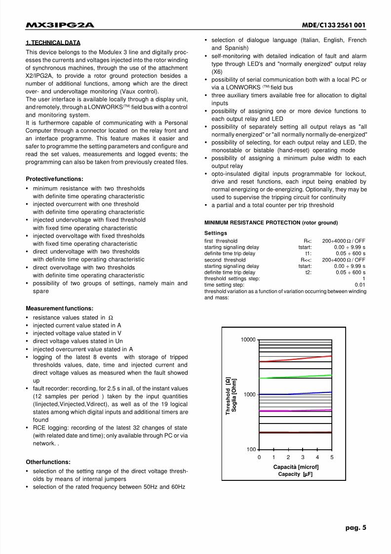
MINIMUM RESISTANCE PROTECTION (rotor ground)
Settings
first threshold R<: 200÷4000Ω / OFFstarting signalling delay tstart: 0.00 ÷ 9.99 sdefinite time trip delay t1: 0.05 ÷ 600 s
second threshold R<<: 200÷4000Ω / OFFstarting signalling delay tstart: 0.00 ÷ 9.99 sdefinite time trip delay t2: 0.05 ÷ 600 sthreshold settings step: 1time setting step: 0.01
threshold variation as a function of variation occurring between windingand mass:
Capacity [µµµµµF]
T h r e s h o l d
[ Ω Ω Ω Ω Ω ]

7/16/2019 Mx3IPG2A
http://slidepdf.com/reader/full/mx3ipg2a 6/40
pag. 6
MDE/C133 2561 001MX3IPG2A
OVERCURRENT PROTECTION
measurement range: 0 ÷ 1.2 A
Settings
threshold I~>: 0.01÷0.10 A / OFF
starting signalling delay tstart: 0.00 ÷ 9.99 sdefinite time trip delay t3: 0.05 ÷ 600 sthreshold settings step: 0.001time setting step: 0.01
UNDER/OVERVOLTAGE PROTECTION (diagnostics)
undervoltage threshold : 28 Vtrip delay : 2 sovervoltage threshold : 52 Vtrip delay : 2 s
DIRECT UNDER/OVERVOLTAGE PROTECTION
rated voltage (jumper in S20) Un: 30 ÷ 300 Vrated voltage (jumper in S21) Un: 3 ÷ 30 Vrated voltage (jumper in S22) Un: 0.3 ÷ 3 Vrated voltage (jumper in S23) Un: 0.03 ÷ 0.3 Vfirst undervoltage threshold U-<: 0.5 ÷ 1.2 Un / OFF
starting signalling delay tstart: 0.00 ÷ 9.99 s
trip delay t4: 0.02 ÷ 600.00 ssecond threshold di minima tensione U-<<: 0.5 ÷ 1.2 Un / OFFstarting signalling delay tstart: 0.00 ÷ 9.99 strip delay t5: 0.02 ÷ 600.00 s
first overvoltage threshold U->>: 0.5 ÷ 1.2 Un / OFFstarting signalling delay tstart: 0.00 ÷ 9.99 strip delay t6: 0.02 ÷ 600.00 ssecond overvoltage threshold U->>: 0.5 ÷ 1.2 Un / OFFstarting signalling delay tstart: 0.00 ÷ 9.99 s
trip delay t7: 0.02 ÷ 600.00 ssettings step: 0.01
ADDITIONAL SETTINGS
rated frequency fn: 50 or 60 Hz
minimum pulse width of end relays timp: 0.02 ÷ 1 s
additional timer tX1: 0.02 ÷ 600 sadditional timer tX2: 0.02 ÷ 600 sadditional timer tX3: 0.02 ÷ 600 s
Auxiliary power supply
MX3IPG2A.11, .61 and .71 versionsUaux: 19 ÷ 100 VccUaux: 19 ÷ 72 Vca
MX3IPG2A.12, .62 and .72 versionsUaux: 64 ÷ 300 Vcc
Uaux: 64 ÷ 275 VcaX2/IPG2A attachment Uaux: 10 ÷ 315 Vcafrequency for Uaux in c.a.: 47 ÷ 63 Hzburden (minimum/maximum) in d.c.: 5 W / 10 Wburden (minimum/maximum) in a.c.: 10VA / 20VA
burden of X2/IPG2A attachment in c.a.: 5 VA
Output contact rating
rated current: 5 Abreaking power (110 Vcc; L/R= 40 ms; 105 operations): 0.3 Amake and carry for 0.5 s: 30 A
mechanical durability: 106 operations
Digital inputs
MX3IPG2A.11, .61 and .71 versionsUaux IN DIG: 19 ÷ 100 Vcc
maximum series lead resistance: 8.8 kohm
with additional external resistor, rated 4.7 kohm 2 W 30 ÷ 150 Vccwith additional external resistor rated 18 kohm 7 W
50 ÷ 300 VccMX3IPG2A.12, .62 and .72 versions
Uaux IN DIG: 64 ÷ 264 Vcc
maximum series lead resistance: 48 kohmwith additional external resistor rated 6.8 kohm 1 W 75 ÷ 300 Vcc
Errors of measuring equipment
Resistance threshold
relative error: ≤ 3 % of set value (with min. value 20 Ohm)consistency : ≤ 1 % of set value
Current threshold
relative error: ≤ 3 % of set value + 0.005 Aconsistency: ≤ 1 % of set value + 0.005 A
Voltage thresholds
relative error : ≤ 2.5% + 1 Vconsistency : ≤ 1% + 1 V
Direct voltage thresholds
relative error (selector Un: S20): ≤ 3% (minimum 1 V)(selector Un: S21): ≤ 3% (minimum 100 mV)(selector Un: S22): ≤ 3% (minimum 10 mV)
(selector Un: S23): ≤ 3% (minimum 1 mV)relative error : (selector Un: S20): ≤ 1% (minimum 1 V)
(selector Un: S21): ≤ 1% (minimum 100 mV)(selector Un: S22): ≤ 1% (minimum 10 mV)(selector Un: S23): ≤ 1% (minimum 1 mV)
Error variationas frequency varies within the range ± 5% fn
and with ≤ 5% distortion factor
Current threshold
relative error: ≤ 1 % of set value + 0.0025 A
Voltage threshold
relative error : ≤ 1% + 1 V
as temperature and Uaux vary within the operating range
Current threshold
relative error: ≤ 0.5% of set value + 0.001 A
Voltage threshold
relative error : ≤ 0.5% + 1 V
Direct voltage threshold
relative error (selector Un: S20): ≤ 0.5% (minimum 1 V)(selector Un: S21): ≤ 0.5% (minimum 100 mV)
(selector Un: S22): ≤ 0.5% (minimum 10 mV)(selector Un: S23): ≤ 0.5% (minimum 1 mV)
for asymmetric values
transient overreach: ≤ 5%
Time errors
relative error on definite times: ≤ 3% or 20 ms
consistency on definite times: ≤ 1% or 20 ms
Variation of time errors
as temperature and Uaux vary within the operating range
relative error on definite times: ≤ 0.5% or 10 ms
Other characteristics
reset ratio for maximum thresholds: > 0.95reset ratio for minimum thresholds: < 1.05
reset time: ≤ 50 msovershoot: ≤ 30 ms
Operating ranges
service temperature: -10 °C ÷ +60 °C
storage and transport temperature: -25 °C ÷ +80 °Crelative humidity: < 95% with no formation of condensatevibration: IEC255-21-1; class 2; 0.075mm 10-60Hz; 1g 60-500Hz
Weight
total: 2.5 Kg

7/16/2019 Mx3IPG2A
http://slidepdf.com/reader/full/mx3ipg2a 7/40
pag. 7
MDE/C133 2561 001MX3IPG2A
Protection Class
device: IP52
upon request when flush-mounted in a panel: IP66terminal board with mounted cover: IP20
Insulation
To ground and between two independent circuits whatsoever:
2 kV, 50 Hz per minute
Impulse test: 5 kV 1.2/50 µs
Electromagnetic compatibility
89/336/CEE : EN50081-2 EN50082-2 DirectiveFor industrial environments
UNIPEDE NORM(SPEC)13 "Automation and control apparatus forgenerating station and substation"
ENEL R_EMC_02 "Apparati di automazione e controllo per centrali e
stazioni elettriche".conditions of electromagnetic compatibility:IEC 1000-4-8 EN 61000-4-8 lev.5; 1000 A/m
IEC 1000-4-10 EN 61000-4-10 lev.5; 100 A/mIEC 1000-4-3 ENV 50140 lev.3; 10 V/m
77B(Sec)1 ENV 50204 lev.3; 10 V/m
IEC 1000-4-2 EN 61000-4-2 lev.4; 8kV contact;15kV air-break77A/120/CD lev.4 / 3; 300V / 10-1-1-10 V
IEC 1000-4-5 EN 61000-4-5 lev.4; 4kV 1.2/50 µsIEC 1000-4-12 EN 61000-4-12 lev.3; 2.5 kV
IEC 1000-4-4 EN 61000-4-4 lev.4; 4 kV77B/144/DIS ENV 50141 lev.3; 10 V77A(Sec)99 lev.2; 10%
IEC 1000-4-11 EN 61000-4-11 > 20 msIEC/CISPR 11 EN 55011 group 1 class A
Reference standards
CEI 95-1 EN 60255-6 IEC 255
Low voltage directive 73/23/CEE
2. GENERAL CHARACTERISTICS
The device features a mechanical casing that is 4U in height,
and as wide as to allow up to 4 pieces to be accommodated
in a 19" rack, in addition to normal flush mounting.
The casing is made of a hot-galvanized PVC-coated plate
frame inside which the moving part that carries all the elec-
tronic circuits and the local interface slides on guides. The pull-
out action is facilitated by the presence of special "handles"
which, when the device is "plugged in", are also used to lock
the two parts. The aluminium frame of the moving part renders
the latter excellently rigid.
The device-system interface terminal blocks are located on
top of the casing and, for each electrical connection, a screw
clamp is available apt to receive up to 2 cable terminals, 4mm2
in size. Using a special accessory that is included in the
supply, the connection can also be made through Faston
members.
Special error-fighting codes do not allow relays other than
those compatible with the housing to be inserted.
A cover lid classes the terminal block within the IP20 protectionclass.
When the moving part is pulled out, the current inputs are
automatically short-circuited, whereas the voltage and auxil-
iary circuits are disconnected.
The device front bears two labels:
one plate lists the factory configuration of the device, namely
auxiliary voltage, rated current and frequency;
The other plate, always in accordance with the factory configu-
ration, provides an explanation of LED's indications.
Both labels are easily replaced with new ones, which can bear
any information as required by the client.
As far as the factory configuration relevant to output relays,LED's, digital inputs and relevant settings are concerned,
please refer to tables A, B and C.

7/16/2019 Mx3IPG2A
http://slidepdf.com/reader/full/mx3ipg2a 8/40
pag. 8
MDE/C133 2561 001MX3IPG2A
2.1 Selecting rated values
The selection of the rated current between 1 or 5 Ampères for
phase protection is made by acting on a jumper that is located
by one of the following points: S20, S21, S22, S23, which can
be reached once the relay has been pulled out (see fig. 1, 4a,
4b, 4c, 4d).
I WARNING
Dangerous voltages may remain in the device even when thelatter has been de-energized or pulled-out of its casing
(capacitor's memory)
fig. 1
3. OPERATION
3.1 Underresistance protection (rotor ground)
The underresistance protection works by comparing the ratio
between voltage and current injected into the attachment X2/
IPG2A with the set thresholds (R<,R<<): when the calculated
resistance falls below a given threshold,causes the tstart and
the trip timers t1 t2 to trip. If the value remains below thethreshold, once the associated tstart delay is over, the delayed
start command is sent.
If the tripping timers also reach the set overtime, the tripping
command is sent; the partial and total counters related to the
tripped threshold increase their counts and the event logging
session starts.
If a special digital input is enabled which has been set to lock
one or more thresholds, the starting registers are held at zero,
thus preventing operation as long as the input remains ena-
bled.
Threshold R< has a definite time characteristic in the form:
t = t1
3.2 Overcurrent protection (input I)
The device is equipped with an overcurrent threshold (injected
by attachment X2/IPG2A) associated to a tstart and a trip timer.
The overcurrent threshold trip may be locked by feeding a
special digital input purposely set to suit the purpose.
3.3 Undervoltage protection (diagnostics - input U)
The device is equipped with an undervoltage threshold (ap-
plied to attachment X2/IPG2A) associated to a timer. The trip
of the undervoltage threshold can be locked by feeding aspecial digital input purposely set to suit the purpose.
3.4 Overvoltage protection (diagnostics - input U)
The device is equipped with an overvoltage threshold (injected
by the attachment X2/IPG2A) associated to a timer. The trip of
the undervoltage threshold can be locked by feeding a special
digital input purposely set to suit the purpose.
3.5 Direct undervoltage protection (input Ucc)
The device is equipped with a direct undervoltage threshold
associated to a tstart and a trip timer. The direct undervoltagethreshold trip can be locked by feeding a special digital input
purposely set to suit the purpose.
3.6 Direct overvoltage protection (input Ucc)
The device is equipped with a direct overvoltage threshold
associated to a tstart and a trip timer. The direct overvoltage
threshold trip can be locked by feeding a special digital input
purposely set to suit the purpose.
TOP
RELAYFRONT

7/16/2019 Mx3IPG2A
http://slidepdf.com/reader/full/mx3ipg2a 9/40
pag. 9
MDE/C133 2561 001MX3IPG2A
3.7 Main and spare settings
The device can store two groups of settings, named 'main' and
'spare' settings, which can be programmed through the
keyboard, a Personal Computer or a network.
The current settings are indicated on the display unit with the
text 'SETTINGS IN USE'.
The device, notwithstanding the selections made, can be
"forced" to use the SPARE settings. Such forcing can be
enabled from the network or through a continuous signal to be
sent to the digital input (IN DIG 1), previously set to implement
this function. This condition is signalled by the presence of the
characters <!> next to the selected settings; when the signal
drops, the previously selected group of settings is enabled
again, whereas the characters <!> disappear (see paragraph
6.1.3).
4. ADDITIONAL FUNCTIONS
4.1 Diagnostics
Diagnostic activities are envisaged which are automatically
carried out upon powering on the device as well as from time
to time during the running, and which provide the following
actions:
- signalling fault or failure conditions. This signal de-energizes the diagnostic relay, turns off the green LED
(indicating running system) and lights up the red LED
(indicating system failure).
- system lock-out in the event of faults that might entail ill-
timed operation (VITAL FAULTS).
- failure code display.
The following failures are classed as NON-VITAL FAULTS:
- output relay(s) (X1 - X5) failure
- communication failure
- internal clock failure
The following failures are classed as VITAL FAULTS:
- feeder failure
- EEPROM failure
- internal or external RAM failure
- Analogue/Digital converter failure
In the presence of vital faults, the device will automatically
displays the fault code; this condition can only be reset, if the
equipment allows this condition to be reset, by enabling the
"settings change' command.
In the event of , upon starting up the equipment, an EEPROM
failure making it impossible to retrieve the information on the
selected dialogue language, the device will continue working
using Italian as the default dialogue language.
The device includes the 'Watch Dog' function.
The diagnostic activity is also aimed at signalling any conditionof "inhibited equipment"; this condition is displayed with a
dedicated code, the diagnostic relay is de-energized and the
red LED (faulty device) lights up. This condition can only be
reset by enabling the 'change settings' command.
The diagnostic menu also indicates the date when last changes
were made to the equipment.
4.2 Output circuits
The output circuits are composed of six relays, each of them
equipped with two contacts (see block diagram).
The X6 relay, normally energized, is strictly assigned to the
diagnostic function.Each of the five relays left, if duly programmed from the
keyboard, a Personal Computer or a network, can be:
- set to perform one or more functions
- preset for:
- monostable operation: immediate return to the quiescent
position when the cause that operated it is removed.
- bistable operation (MEMOR): the tripping position is main-
tained until a reset signal comes from the front push-button,
the digital input or the serial connection.
- a minimum duration of the signal or command (t_IMP).
The output relays, except for the diagnostic relay, can all be
simultaneously set to "normally energized" (NORMAL.ON=ON)or "normally de-energized" (NORMAL.ON=OFF): this selection
is made by acting on the settings change function.

7/16/2019 Mx3IPG2A
http://slidepdf.com/reader/full/mx3ipg2a 10/40
pag. 10
MDE/C133 2561 001MX3IPG2A
4.3 LED signalling circuits
The signalling circuits are made of twelve LED's (see fig. 5).
Four LED's are rigorously assigned to previously established
signalling functions:
- (Uaux) green LED ON in the presence of input voltage and
with correct feeder output voltage values
- (RUN) green LED ON with fixed light in normal conditions
and blinking during setting changing and testing functions
- (RUN) red LED ON with fixed light when the diagnostic
detects a fault or a condition of inhibition.
- (Rx Tx) green LED ON with fixed light when the device is
correctly connected, blinking with the communication
board not enabled or not properly set; OFF when the
communication board is not present on the device.
Each of the eight LED's left, if duly programmed from the
keyboard, a Personal Computer or the network, can be:
- set to perform one or more functions
- preset for:
- monostable operation; it immediately goes off when the
cause that made it go on is removed- bistable (MEMOR) operation; the LED remains ON until a
reset signal is sent from the front push-button, the digital
input or the serial connection. Any failure of auxiliary voltage
only entails a momentary loss of the luminous signals,
which come back again as soon as voltage is restored.
A pocket is provided close to the LED's, where LED describing
labels can be placed.
4.4 Digital Inputs
Each of the three optoisolated inputs can be associated with
one or more protection functions by duly programming them
through keyboard, Personal Computer or via network. Theinput voltage may happen not to match the auxiliary voltage of
the device.
The digital inputs can be programmed to be enabled by normal
energizing or normal de-energizing.
4.5 Additional timers
All the optoisolated inputs (IN DIG 1,IN DIG 2,IN DIG 3) can be
programmed to be associated with additional timers (t_X1,
t_X2, t_X3).
When the programmed input is energized, the associated
additional timer is started, and if the timer reaches the overtime
status, the tripping signal is sent and maintained until the input
is reset.
4.6 Counters
Each tripping threshold is associated with a partial and total
counter.
The counters work within the 0-9999 range; if number 9999 is
exceeded, the counter is automatically reset and the count
restarts from the beginning.
All of the partial counters can be reset by acting through the
keyboard, a Personal Computer or via network.
4.7 Event logging
When a tripping event occurs, the following information is
stored in the circulating memory:
- first operated threshold
- day, month, year, time, minute, second and millisecond
identifying the tripping moment.
- values measured when the tripping occurred.
The information concerning one trip is called event.
The circulating memory allows the last 8 events to be stored,
and when this number is exceeded, a new record replaces the
older: the last event is stored as EVENT 1.
The stored events can be read from the front display unit or from
a PC serially connected to the device.
The device can also record the latest 32 changes of state (with
related date and time) and make them available exclusively
through PC or via network.
4.8 Measurements
The device is in a position to display the effective present
values of resistance, expressed in Ohm, direct voltage, ex-
pressed in Un, injected alternating voltage stated in V and
injected alternating current stated in A .
The unit also displays the maximum value of injected alternat-
ing current stated in A ever measured by the latest 'Reset
maximum values'
4.9 Test
Besides the normal diagnostic already dealt with, the device
also offers, in the TEST mode, the possibility of testing the
LED's, the display unit and the output relays.
- The LED test turns on all the LED's, from L1 to L8, and thedisplay unit (LCD) for two seconds.
Once the test is over, the LED's that were supposed to be
ON before the test remain ON and the display unit goes back
to the previous information displayed. The test can also be
performed in any operating condition, without affecting the
operation in progress.
- the relay test allows the output relays X1 to X5 to be
sequentially selected and checked for correct operation. In
this way, any external signalling or control circuit can be
tested, too.
The tested relay remains energized for 150 to 200 ms.
If starting or tripping commands are already present, the
test is not carried out and a dedicated message appears on
the display unit.
The test on auxiliary relays does not affect counters, event
logs and LED's.
4.10 Alphanumeric user identifier
The device can be identified in the plant by an alphanumeric
code, which can be set by the user directly on the equipment
or from a PC. With a network-linked device, the alphanumeric
code can only be modified by operating through the network.

7/16/2019 Mx3IPG2A
http://slidepdf.com/reader/full/mx3ipg2a 11/40
pag. 11
MDE/C133 2561 001MX3IPG2A
4.11 Language
The device can display information in four languages: Italian,
English, French and Spanish. The language can be selected
through the keyboard.
4.12 LCD settings
The display can be set for fixed (OFF) or timed (ON) back-lighting; in the last case, the display lights up for 300s any time
a key is pressed .
4.13 Inhibiting operation - Deconfiguration via network
Inhibiting the device is required in operating plants, to avoid
inefficiency on feeding a protection whose settings are un-
known or need to be changed.
The inhibition is performed by holding the settings change
button pressed for about 2 s,while injecting the auxiliary
voltage until the following message is displayed:[ BLOC ]
[ ]
On releasing the push-button, the condition of inhibited device
is signalled by a diagnostic message of P fault.
The normal operating conditions can only be restored by
moving to the settings change function, which is enabled at all
events; a temporary loss of the auxiliary voltage supply does
not affect the inhibited state of the device.
If the device is also equipped with a field-bus board, by holding
the settings change push-button further pressed for about 2s,
in the BLOC state, the device will display:[ NET RESET ? ]
[_ NO YES _]
if a confirmation is provided, the device can also be made lose
its network configuration.
The full procedure for inhibiting and de-configuring the device
via network must be enacted any time you need to replace the
unit.
By resetting an inhibited and deconfigured unit, a K fault
message is displayed and remains displayed until the unit is
configured anew.
Operation can only be reset by moving to the settings change
function, which is enabled in any case.fig. 2
RELAYFRONT
TOP SIDE
BOARD
NOTENABLE
BOARDENABLE
A-A VIEW A-A VIEW
A-A VIEW
I CAUTION
Hazardous voltages can remain in the device even when
the latter has been de-energized or pulled out of its casing
(condenser memory).
4.14 Serial communication on LONWORKS (TM)bus
The device, in the version including the special bus board, can
communicate with a central monitoring and control system at
a speed equalling 1.2 5 Mbaud. The connection to the field bus
is made through terminals: 43 and 45.
The communication board, which can be also added later, is
only enabled if the special S6 jumper is correctly connected,
while it is not in the case the jump is connected in vertical
position across S5 and S6 (see fig. 2).
If the S6 jumper is connected when the communication board
is not present, the diagnostic function displays a message of
failure, behaving as if the board was present and faulty.
Appendix A lists the parameters available for the network.

7/16/2019 Mx3IPG2A
http://slidepdf.com/reader/full/mx3ipg2a 12/40
pag. 12
MDE/C133 2561 001MX3IPG2A
4.15 RS485 serial communication and MODBUS protocol
Concerning the communication of devices provided with
software version 2.00 and subsequent, three different versions
are possible:
- whitout any communication card (version
MX3IPG2A .11 e .12);
- provided with LonWorks(TM) communication card (version
MX3IPG2A .61 e .62);
- provided with Modbus communication card (version
MX3IPG2A .71 e .72);
The identification of the installed communication card is
automatic.
When using an unit provided with LonWorks (TM) communication
card, it's required first to effect the relay wiring according to its
wiring diagram and later proceed with the configuration of all
connected devices; the automatic configuration of connected
devices is possible by connecting a PC provided with PCLTA10
or SLTA10 card, in which CORMOX2 software has been
installed.
When using a device provided with Modbus communicationthe configuration of each relay may be realized by the front
interface, or by the IRMA2 program installed on a PC connected
to the relay via front plug. The configuration may be realized
also on relays not jet connected together and may be eventually
organized in files together with all other settings.
Modbus communication card configuration requires:
PARAMETER VALUE
Speed 300 Baud600 Baud
1200 Baud2400 Baud
4800 Baud9600 Baud
19200 Baud
38400 Baud
Parity NONEEVEN
ODD
Data Bit 7
8
Stop Bit 1
2
Address 1 - 255 (0 broadcast)
This parameters can be programmed in local or remote mode.
So, the following extension of the 'RELAY DATA' menu is
available:
[MX3IPG2A ] relay type
[Sw Vers 2.00/01] software version
ñ ò
[PLANT IDENTIFIER]
[GenPan ] ðplant identifier
ñ ò
[SPEED 38400 Bb] ðspeed setting
[PARITY NONE ] ðparity setting
ñ ò
[DATA BIT 8 ] ðdata bit setting[STOP BIT 1 ] ðstop bit setting
ñ ò
[ADDRESS 111 ] ðaddress setting
[ ]
On demand is available documentation about LonWorks(TM) and Modbusversions.
4.16 Fault recorder
The device can record the course of input currents (Ia, Ib, Ic, Io)
and the logic states of the 8 LED's, the 5 auxiliary relays, the
3 digital inputs and the 3 additional timers. The total recording
time equals 2.5s, and can be divided into variable time before
start-up and variable time after start-up. The fault recorder
function can be started for: tstart, tripping, enabling of digital
inputs and timers. The selection of the starting parameters,
the graphic display and reset of fault recorder can be made
through a PC or a network. The function can even be reset by
interrupting the auxiliary voltage for a short while.
4.17 Checking tripping circuits for continuity
The use of a digital input enabled by normal de-energizing
combined with one of the TX timers allows the tripping coil
circuit to be monitored for continuity, whether the breaker is
closed or open.

7/16/2019 Mx3IPG2A
http://slidepdf.com/reader/full/mx3ipg2a 13/40
pag. 13
MDE/C133 2561 001MX3IPG2A
5.LOCAL INTERFACE Key It scrolls the menu to the left or selects
the digit to be changed, if the settings
change function is enabled. [ï]
Key It resets the stored LED signals if the
cause has been removed, or the par-
tial counters, if you are in the "display
counters" menu.
It takes the end relays to quiescent
state when they are set to bistable
operation.
Key If pressed for at least 2s, this key
enables the settings to be changed.
When the settings change is ena-
bled, the green LED (RUN) lights up
blinking. If pressed once again for at
least 2s, the system goes back to the
normal running conditions and, pro-
vided that a confirmation is given, the
new settings become the current
ones (the key can only be reached by
removing the cover). During the set-
ting change operations, the device
continues working with the old set-
tings. If the changes made are con-
firmed in the presence of a fault, they
are not made the current ones until
the event is over: the interrupt state is
signalled for 3s by a message on the
display unit, after which you are
prompted to confirm the changes
made.
If pressed upon feeding the device
with auxiliary voltage until a failure
message appears on the display,
this key inhibits the device from oper-
ating.
Keys If simultaneously
pressed for at least 2s, these keys
enable the protection to be tested.
When the testing activity is enabled,
the green LED (RUN) lights up blink-
ing.
If simultaneously pressed for at least
2s during the TEST routine, these
keys enable you to leave the protec-
tion testing mode.
The local interface is made up of:- An LCD display unit organized on two lines of sixteen
characters each.
Through a special keyboard-controlled scanning, the dis-
play unit enables the settings to be read and changed, the
measurements, the counters, the logged events and the
diagnostic information to be read.
- A keyboard or keypad made up of six keys, five of which can
even be reached when the cover is fitted through a special
link.
In addition to the above-mentioned scanning, the keyboard
is also used to change the settings, to carry out tests that
require commands to be sent and stored indications to be
set to zero. The keys that can be reached when the cover is
fitted only allow for read-out and reset operations.
Key It scrolls the menu upwards or in-
creases a value, if the settings
change function is enabled. [ñ]
Key It scrolls the menu downwards or
decreases a value, if the settings
change function is enabled. [ò]
Key It scrolls the menu to the right or se-
lects the digit to be changed, if the
settings change function is enabled
[ð].

7/16/2019 Mx3IPG2A
http://slidepdf.com/reader/full/mx3ipg2a 14/40
pag. 14
MDE/C133 2561 001MX3IPG2A
- Twelve LED's, four of which are rigorously dedicated to
general running functions.
- A four-pin connector in compliance with FCC 68.
By means of a special optoelectrical adapter, an optical
fibre cable and a RS232 optical converter, it allows the
device to be locally linked with a personal computer.
The P.C., through a special interface programme, makes
it possible to read and change the settings, to read themeasurements, the counters, the logged events, the diag-
nostic information and the fault recorder.
6. LCD MENU STRUCTURE
6.1 MAIN READING MENU
The device has a main menu, leading to several sub-menus
(tree structure). All the displays can be made permanent .
[R Ω ] Present resistance value[U- Un ] Present direct voltage value
ñ ò
[MENU: ENGLISH] Dialogue language[ ] ð change dialogue language
ñ ò
[DATE ] present date and time[TIME ] ð change date and time
ñ ò
[SETTINGS: ] view settings in use[ MAIN]
ñ ò
[SETTINGS READING] ð view main settings[MAIN ]
ñ ò
[SETTINGS READING] ð view spare settings
[SPARE ]
ñ ò
[ MEASUREMENTS ] ð View/reset present and stored[ ] measurements
ñ ò
[ COUNTERS ] ð view counters and[ P=RESETTABLE ] reset partial counters
ñ ò
[ EVENTS ] ð view[EVENTO 1=ULTIMO] stored events
ñ ò
[ OUTPUT RELAYS ] ð view output relay[ ] settings
ñ ò
[ DIGITAL ] ð view digital input[ INPUTS ] settings
ñ ò
[ LED ] ð view LED settings[ ]
ñ ò
[ RELAY DATA ] ð view model - soft. release[ ] and plant identifier
ñ ò
[ DIAGNOSTIC ] ð view faults[ ] date of last change
6.1.1 Change dialogue language
The default language is ITALIAN.Here follows an example showing how to change the dialogue
language. Suppose we wish to set ENGLISH as the desired
language.
a) Press the key ò or ñ until the following message appears
on the display:[MENU: ITALIAN ]
[ ]
b) By pressing the key ð the language change function is
enabled, and the following message appears on the display:[MENU: ITALIAN ]
[ ]

7/16/2019 Mx3IPG2A
http://slidepdf.com/reader/full/mx3ipg2a 15/40
pag. 15
MDE/C133 2561 001MX3IPG2A
By pressingò orñ you scroll the stored languages menu. Forthe purpose of our example, we must stop when the following
message is displayed:[MENU: ENGLISH ]
[ ]
d) By pressing ï you confirm the selected dialogue language
and go back to the main menu. The following message appears
on the display:[MENU: ENGLISH ]
[ ]
6.1.2 Change date and time
Access to "change date/time" is denied when the protection is
network-connected. If the network connection is made after
entering the change function, the local changes are not ena-
bled.
Let us assume we wish to change the starting date 10/06/93
into 24/05/95.
a) Press the keyò
orñ
until the display shows:[DATE 10/06/93]
[TIME 9:38:43]
b) By pressing the key ð the change function is enabled and
the following message appears on the display:[DATE 10/06/93]
[TIME 9:38:43]
c) By pressingð select the value to be changed. To select the
last digit that makes up the date, pressð six times, the displays
will show:[DATE 10/06/93]
[TIME 9:38:43]
d) By pressing ñ, increase the selected value. Hold the key
pressed until the display shows:[DATE 10/06/95]
[TIME 9:38:43]
e) By pressing ï , select the fourth digit that makes up the date,
the display will show:[DATE 10/06/95]
[TIME 9:38:43]
f) By pressing ò, decrease the selected value until the display
shows:[DATE 10/05/95]
[TIME 9:38:43]
g) By pressing ï twice further, select the second digit that
makes up the date, and the display will show:[DATE 10/06/95]
[TIME 9:38:43]
h) By pressing ñ, change the selected value (upon reachingnumber 9, the tens will go up by one unit) until the display
shows:[DATE 24/05/95]
[TIME 9:38:43]
i) Press ï until you move to the beginning of the line. The
display will show: [DATE 24/05/95]
[TIME 9:38:43]
j) By pressing ò the "change time" function is enabled. The
steps are the same as those described in c) to i).
The device does not accept time or date settings that do not
exist.
The time counting starts upon moving from the digits that make
up the time to the wording TIME at the beginning of the line.
k) By pressingï
the changes made are confirmed and thesystem moves back to the main menu. The display will show:
[DATE 24/05/95]
[TIME 9:38:43]
6.1.3 Display settings in use
a) Press ò or ñ until the display shows, for instance:[SETTINGS IN USE:]
[ MAIN]
The second line will display the group of settings the device
currently uses.
Any <!> possibly displayed, notwithstanding the contents of the
second line, indicates the device is working with the SPAREsettings.
[SETTINGS IN USE:]
[ <!> MAIN]
The device will continue working with the SPARE settings aslong as the "change settings" command sent by the IN DIG1
digital input remains enabled. When the <!> characters disap-
pear, the device restarts working with the group of settingsdisplayed.
6.1.4 Display main settings
a) Press ò or ñ until the display shows:[SETTINGS READING]
[ MAIN ]
b) By pressing ð, the main settings display sub-menu is
entered, by pressingò orñ the following sub-menu is scrolled:
rated frequency fn
direct rated voltage setting range (**) S..direct rated voltage Un
first underresistance threshold R<starting signalling delay R< tstart
trip delay R< t1
second underresistance threshold R<<starting signalling delay R<< tstart
trip delay R<< t2alternating overcurrent threshold I~>
starting signalling delay I~> tstart
trip delay I~> t3first direct undervoltage threshold U-<
U-< starting signalling delay tstarttrip delay U-< t4
second direct undervoltage threshold U-<<
U-<< starting signalling delay tstarttrip delay U-<< t5
first direct overvoltage threshold U->U-> starting signalling delay tstart
trip delay U-> t6

7/16/2019 Mx3IPG2A
http://slidepdf.com/reader/full/mx3ipg2a 16/40
pag. 16
MDE/C133 2561 001MX3IPG2A
second direct overvoltage threshold U->>U->> starting signalling delay tstart
trip delay U->> t7
additional timer t_X1additional timer t_X2
additional timer t_X3min. pulse width of end relays t_IMP
(**) the settings range relies on jumper S20, S21, S22 or S23which are closed as follows:
jumper closed setting rangeS20 30.00 - 300.00 V
S21 3.00 - 30.00 V
S22 0.30 - 3.00 VS23 0.03 - 0.30 V
c) By pressing ï,anywhere in the sub-menu, you will go back
to the main viewing menu:[SETTINGS READING]
[MAIN ]
6.1.5 Viewing spare settingsa) Press ò or ñ until the display unit shows:
[SETTINGS READING]
[SPARE ]
b)Press the keyð to enter the spare setting viewing menu, then
press ò or ñ to scroll across the whole submenu that lists:
first underresistance threshold R<starting signalling delay R< tstart
trip delay R< t1second underresistance threshold R<<
starting signalling delay R<< tstart
trip delay R<< t2
alternating overcurrent threshold I~>starting signalling delay I~> tstart
trip delay I~> t3first direct undervoltage threshold U-<
starting signalling delay U-< tstarttrip delay U-< t4
second direct undervoltage threshold U-<<
starting signalling delay U-<< tstarttrip delay U-<< t5
first direct overvoltage threshold U->starting signalling delay U-> tstart
trip delay U-> t6
second direct overvoltage threshold U->>starting signalling delay U->> tstart
trip delay U->> t7
Those parameters that are not present in the SPARE menu
take the same values as the MAIN settings.
c) By pressing the key ï anywhere in the sub-menu, you go back
to the main reading menu:
[SETTINGS READING]
[ SPARE ]
6.1.6 Display current and stored measured values
a) Press the key ò or ñ until the display shows:[ MEASUREMENTS ]
[ ]
b) By pressing the key ð you will enter the measurement
display menu, and by pressing the keyò orñ the following sub-
menu will be scrolled across:present resistance value in Ohm R(*)
present direct voltage in Un U-
present injected alternating voltage value in Volt U~
present injected alternating current in Ampere I~
injected overcurrent value in Ampere I~MAX
c) By pressing RESET you may cancel the maximum stored
values being displayed.
By pressing the key ï anywhere in the submenu, you will go
back to the main reading menu:[ MEASUREMENTS ]
[ ]
(*) When resistance cannot be measured, the symbol ---- will
be displayed; when resistance exceeds 6500 Ohm, the sym-
bol >6500 Ω will be displayed.
6.1.7 Viewing counters
a) Press the key ò or ñ until the display shows:[ COUNTERS ]
[P =RESETTABLE ]
b) By pressing the keyð you will enter the counter display sub-
menu, and by pressing the key ò or ñ the following sub-menu
will be vertically scrolled across:
total trips of first underresistance threshold R< Tpartial trips of first underresistance threshold R< P
total trips of second underresistance threshold R<< T
partial trips of sec. underresistance threshold R<< P
total trips of alternating overcurrent threshold I~> Tpartial trips of alternating overcurrent threshold I~> P
total trips of first direct undervoltage threshold U-< Tpartial trips of first direct undervoltage threshold U-< P
total trips of sec. direct undervoltage threshold U-<< Tpartial trips of sec. direct undervoltage threshold U-<< P
total trips of first direct overvoltage threshold U-> T
part. trips of first direct overvoltage threshold U-> Ptotal trips of sec. direct overvoltage threshold U->> T
partial trips of sec. direct overvoltage threshold U->>P
c) By pressing the RESET button, the partial counter being
displayed can be reset.
d) By pressing the keyï , you go back to the main display menu:
[ COUNTERS ]
[ P =RESETTABLE ]
6.1.8 Viewing events
a) Press ò or ñ until the display shows:[ EVENTS ]
[EVENT 1=LAST]
b) By pressing ð you enter the sub-menu where the eight
events to be stored can be selected. The display shows:[EVEN.1 DD/MM/YY ]
[ hh:mm:ss.xxx ]
7/16/2019 Mx3IPG2A
http://slidepdf.com/reader/full/mx3ipg2a 17/40
pag. 17
MDE/C133 2561 001MX3IPG2A
the first line displays the event number, the day, the month andthe year, whereas the second line lists the time, the minutes,
the seconds and thousandths of a second concerning the
event.
c) By pressing the keyò orñ, select the event to be displayed.
Once the selection is made, pressð ; thus, you enter the event
display sub-menu, and by pressing ò or ñ the following sub-
menu is scrolled:
tripped threshold TRIPvalue of resistance in Ω when the trip occurred R_G
value of alternating current in A when the trip occurred I~Gdirect voltage value in mult.of Un when the trip occurredU-_G
d) By pressing ï anywhere in the sub-menu, you go back to
event display sub-menu; to display other events go through step
c) again. By pressingï anywhere in the sub-menu you go back
to the main reading menu:[ EVENTS ]
[EVENT 1=LAST]
6.1.9 Display output relays
a) Press ò or ñ until the display shows:
[OUTPUT RELAYS]
[ ]
b) By pressing ð you enter the sub-menu that displays the
allocation of the auxiliary output relays. The display shows:[REL X12345]
[ON ↑↑↑↑↑]
which stands for the enabling by normal energizing (↑) or de-
energizing (↓) of each relay.
Press ò to scroll across the whole submenu, the display unitwill show:
[R< START]
[REL X..3.5]
the first line displays the function that is associated with therelay or relays listed in the second line.
By pressing the keys ò or ñ the sub-menu is scrolled across.
The functions that can be associated with the output relays are:
delayed start of first underresistance threshold R< START
first underresistance threshold trip R< TRIPdelayed start of sec. underresistance threshold R<< START
second underresistance threshold trip R<< TRIP
delayed start of injected overcurrent threshold I~> STARTalternating overcurrent threshold trip I~> TRIP
undervoltage (diagnostics) threshold trip U~< TRIPovervoltage (diagnostics) threshold trip U~> TRIP
delayed start of first direct undervoltage thresholdU-< STARTfirst direct undervoltage threshold trip U-< TRIP
delayed start of sec. direct undervoltage thresholdU-<< START
sec. direct undervoltage threshold trip U-<< TRIPdelayed start of first direct overvoltage threshold U-> START
first direct overvoltage threshold trip U-> TRIPdelayed start of sec. direct overvoltage thresholdU->> START
direct overvoltage threshold trip U->> TRIP
timer tX1 overtime t_X1 TRIPtimer tX2 overtime t_X2 TRIP
timer tX3 overtime t_X3 TRIP
first digital input fed IN DIG 1second digital input fed IN DIG 2
third digital input fed IN DIG 3
It is furthermore possible to display the output relays that bear
the following settings:minimum pulse width t_IMP
bistable operation MEMOR
c) By pressing the key ï anywhere in the sub-menu, you go
back to the main reading menu:[OUTPUT RELAYS]
[ ]
6.1.10 Viewing digital inputs
a) Press the key ò or ñ until the display shows:[ DIGITAL ]
[ INPUTS ]
b) By pressing the key ð you enter the sub-menu that lists the
allocation of digital inputs. The following message appears onthe display:
[IN DIG 123]
[ON ↑↑↑]
which stands for the enabling by normal energizing (↑) or de-
energizing (↓) of each input.
Press ò to scroll across the whole sub-menu, the display unit
will show:[BLOC. R< ]
[IN DIG ...]
the first line contains the function that is associated with thedigital inputs listed in the second line.
By pressing the keys ò or ñ the sub-menu is scrolled.
The functions that may be associated with the inputs are:
first underresistance threshold trip lock BLOC. R<
second underresistance threshold trip lock BLOC. R<<overcurrent threshold trip lock BLOC. I~>
undervoltage threshold trip lock BLOC. u~<overvoltage threshold trip lock BLOC. u~>
first direct undervoltage threshold trip lock BLOC. U-<
second direct undervoltage threshold trip lock BLOC. U-<<first direct overvoltage threshold trip lock BLOC. U->
second direct overvoltage threshold trip lock BLOC. U->>
timer tX1 start t_X1timer tX2 start t_X2
timer tX3 start t_X3Switching to spare settings SETTINGS SWITCH
LED's and output relays reset RESET
c) By pressing the key ï anywhere in the sub-menu, you go
back to the main reading menu:[ DIGITAL ]
[ INPUTS ]
6.1.11 Display LED's
a) Press the key ò or ñ until the following message appears
on the display:[ LED ]
[ ]

7/16/2019 Mx3IPG2A
http://slidepdf.com/reader/full/mx3ipg2a 18/40
pag. 18
MDE/C133 2561 001MX3IPG2A
b) By pressing the keyð you enter the sub-menu that displays
the LED allocation. The following messages will be displayed:[I> START]
[LED L..3..6.8]
the first line displays the function that is associated with the
LED's listed in the second line.
By pressing the keysò orñ, the sub-menu is vertically scrolled.
The functions that can be associated with the LED's are:
delayed start of first underresistance threshold R< START
first underresistance threshold trip R< TRIP
delayed start of sec. underresistance threshold R<< STARTsecond underresistance threshold trip R<< TRIP
delayed start of injected overcurrent threshold I~> STARTalternating overcurrent threshold trip I~> TRIP
undervoltage (diagnostics) threshold trip U~< TRIP
overvoltage (diagnostics) threshold trip U~> TRIPdelayed start of first direct undervoltage thresholdU-< START
first direct undervoltage threshold trip U-< TRIPdelayed start of sec. direct undervoltage thresholdU-<< START
sec. direct undervoltage threshold trip U-<< TRIP
delayed start of first direct overvoltage threshold U-> STARTfirst direct overvoltage threshold trip U-> TRIP
delayed start of sec. direct overvoltage thresholdU->> STARTdirect overvoltage threshold trip U->> TRIP
timer tX1 overtime t_X1 TRIP
timer tX2 overtime t_X2 TRIPtimer tX3 overtime t_X3 TRIP
first digital input fed IN DIG 1second digital input fed IN DIG 2
third digital input fed IN DIG 3
It is furthermore possible to display the LED's that bear the
following settings:
bistable operation MEMOR
c) By pressing the key ï anywhere in the sub-menu, you go
back to the main reading menu:[ LED ]
[ ]
6.1.12 Viewing relay data
a) Press ò or ñ until the display shows:[ RELAY DATA ]
[ ]
b) By pressing the key ð you enter a sub-menu where the
protection model and the software release are displayed:[MX3IPG2A ]
[Soft Rel. 1.00]
c) By pressing the keyòonce again, the second line will display
the alphanumeric identification code that the user gave to the
device, for instance:[PLANT IDENTIFIER]
[CELL No. 17bis ]
d) By pressing the key ï anywhere in the sub-menu, you go
back to the main reading menu:[ RELAY DATA ]
[ ]
6.1.13 Diagnostic display
1) Fault location
a) Press the key ò or ñ until the following message is
displayed:[ DIAGNOSTIC ]
[ ]
In the presence of VITAL FAULTS, the device automaticallydisplays the window, without needing to enter the diagnostic
menu.
b) By pressing the key ð you enter a sub-menu that displays
the operating state of the relay. The display will show:[LAST SETTING ]
[DD/MM/YY hh:mm]
the second line displays the day, the month, the year, the time
and the minutes of the time when last change was made to the
settings.
c) By pressing the keyò
once again, if the device has notdetected any failure, the following message will be displayed:[ RUNNING ]
[ ]
If NON-VITAL FAULTS are detected, the following message willbe displayed:
[FAULT ]
[ABCDE.....KL ]
whereas, if VITAL FAULTS are detected, the <!> characters will
be displayed, too:[FAULT <!>]
[.....FGHIJ... ]
The second line displays one or more fault identification
codes.
The following table provides the fault codes and the corre-
sponding fault description:
Code fault description
A X1 relay coil interrupted or related driver
B X2 relay coil interrupted or related driver
C X3 relay coil interrupted or related driver
D X4 relay coil interrupted or related driver
E X5 relay coil interrupted or related driver
F internal feeder failure
G EEPROM failure
H Internal RAM failureI External RAM failure
J Analogue to Digital converter
K communication board failure or enabled but
not configured
L internal clock failure
If jumper S6 (see fig.2) that enables the communication board
is connected when the board is not present, the K code shows
up, as if a failure were detected in the board.
d) As far as the NON-VITAL FAULTS are concerned, by pressing
the keyï
anywhere in the sub-menu you go back to the maindisplay menu:[ DIAGNOSTIC ]
[ ]

7/16/2019 Mx3IPG2A
http://slidepdf.com/reader/full/mx3ipg2a 19/40
pag. 19
MDE/C133 2561 001MX3IPG2A
whereas, as regards the VITAL FAULTS, you can only leave the
diagnostic sub-menu, if the device allows you to do that, byentering the “settings change” menu.
2) Inhibited device
The condition of “inhibited device” is displayed as follows:[FAULT <!>]
[..............P ]
This condition can only be reset by entering the "settings
change“ menu (it is however necessary to confirm when you
are prompted to SAVE CHANGES, although no setting has
been changed).
Warning: even simply view the set parameters from the
“settings change” menu, since upon leaving this condition, the
device will not be inhibited any longer.
If, beside inhibiting the device, you have also deconfigured it,
the return to operation causes a fault K message to be
displayed until the unit is configured anew (see paragraph
4.14).
6.2 MAIN SETTING CHANGE MENU
By pressing the key anywhere in the display menus
for at least 2s, the main settings change menu is entered.
Thence, several sub-menus can be entered (tree- structure).
When the settings change function is enabled, the green LED
(RUN) lights up blinking.
If the settings change menu is already acceded through a PC
or a network, any local change is inhibited, and the following
message will be displayed:
[SETTINGS CHANGE]
[NOT AVAILABLE ]
The access priority to the changing function among PC, net-
work and keyboard is time-dependent.
During the settings change operations, the device continues
working with the old settings.
All the displays can be made permanent.
[SETTINGS IN USE:] settings in use
[ MAIN] ð select of current setting group
ñ ò[SETTINGS CHANGE] ð change main settings[MAIN ]
ñ ò
[SETTINGS CHANGE] ð change spare settings[SPARE ]
ñ ò
[ OUTPUT RELAYS ] ð output relays
[ ] settings
ñ ò
[DIGITAL INPUTS ] ð digital inputs
[ ] settings
ñ ò
[ LED ] ð LED's settings[ ]
ñ ò
[ RELAY DATA ] ð setting of[ ] alphanumeric code
ñ ò
[ LCD ] ð permanent display back-lighting
[AUTOMATIC RETURN] (LCD) enabled
By pressing the key anywhere in the changing
menus for at least 2 seconds, you go back to the main display
menu, but you are first prompted to confirm or discard the
changes made:[NEW SET.CONFIRM?]
[< NO YES >]
By pressing ï all the changes made are discarded, whereas
by pressing ð the changes made are confirmed.
The green LED (RUN) stops blinking and becomes perma-
nent.
If upon confirming the changes, a fault is detected, the settings
are not accepted as long as the fault event persists. This stateis signalled for 3s by the following message:
[SETTINGS CHANGE]
[DELAYED ]
once the event is over, you are prompted to confirm the
changes made again.
If the transfer is interrupted is due to a digital input being
enabled which cannot be disabled at the moment and you
need to change the settings, the device must be inhibited; after
that, you can start changing the settings (see paragraphs 4.14
and 6.1.13).
Note: the “change settings” function can even be implemented
when the device is “forced” to use the SPARE SETTINGS. In
such a case, the system only interrupts the selection of
SETTINGS IN USE: MAIN until the external forcing signal
disappears. If a setting is changed when the system is “forced”
from the outside, the following message is displayed:
[SPARE SETTINGS]
[FROM EXT.CONTROL]
All the following examples take their start from the main
settings change menu.
6.2.1 Select current settings group
a) Press the key ò or ñ until the following message is dis-
played:[SETTINGS IN USE:]
[ MAIN]
b) After pressing the keyð, the current settings can start being
changed. The following message is displayed:[SETTINGS IN USE:]
[ MAIN]
c) By pressing ò or ñ, the following message is displayed:[SETTINGS IN USE:]
[ SPARE]

7/16/2019 Mx3IPG2A
http://slidepdf.com/reader/full/mx3ipg2a 20/40
pag. 20
MDE/C133 2561 001MX3IPG2A
d) By pressing the key ï the new selection is confirmed, and
the system goes back to the main settings change menu. Thefollowing message is displayed:
[SETTINGS IN USE:]
[ SPARE]
6.2.2 Change main settings
a) Press the keyò
orñ
until the following message isdisplayed:[SETTINGS CHANGE]
[MAIN ]
b) By pressing the keyð , you enter the main settings change
sub-menu, which contains all the parameters already listed in§ 6.1.3.
c) By pressing the keysò orñ, you can vertically scroll the sub-
menu, and by pressing the keyð you can start changing the
displayed parameter. The change can be made by pressing
the keys ò orñ .
d) By repeatedly pressing the key ï anywhere in the sub-
menu, you go back to the main changing menu:[SETTINGS CHANGE]
[MAIN ]
Example of setting
Let us suppose we need to enable and set the rotor ground
threshold R< to 1015 Ohm starting from an initial setting of
990, OFF.
Go through steps a) and b)
Press ò orñ until the threshold to be changed is selected on
display:[R< OFF]
[R< 0990 Ω ]
Press ð to start changing the selected setting I>>>,the display
unit will show:[R< OFF]
[R< 0990 Ω ]
Press ò or ñ to set it ON and the display will show:
[R< ON ]
[R< 0990 Ω ]
Pressï to move back to the beginning of the line. Thus, by
pressing ò, you may move to the second line.
Pressð to select the digit to be changed.In our case, by pressing 4 times the key ð, the display unit will
show:[R< ON ]
[R< 0990 Ω ]
Press ñ to increase the selected numberuntil the value re-
quired by our example is reached:[R< ON ]
[R< 0995 Ω ]
Now, by pressing ï you select the third digit making up the
setting, the display unit will show:[R< ON ]
[R< 0995 Ω ]
By pressing ñ the digit is changed (on reaching number 9 the
units will increase by 1) until the display unit shows:
[R< ON ]
[R< 1015 Ω ]
Pressï to move back to the beginning of the line and go back
to the main editing menu:[SETTINGS CHANGE]
[MAIN ]
Warning:
In the event of the direct rated voltage setting range being
changed, please remember to move the internal jumper
(S20....S23) as follows:
jumper closed setting range
S20 30.00 - 300.00 V
S21 3.00 - 30.00 VS22 0.30 - 3.00 V
S23 0.03 - 0.30 VThe movement of the jumper causes the setting to be changed,
as the latter is multiplied times 10d
where d is the distancebetween the old and the new jumper, for instance:
old setting
jumper S20setting range 30-300 V
set Un 165 V
new setting jumper S23
setting range 0.03-0.30 Vset Un 165 x 10(20-23)= 0.16 V
6.2.3 Change spare settings
a) Press the key ò or ñ until the following message is
displayed:[SETTINGS CHANGE]
[SPARE ]
b) By pressing the keyð , you enter the spare settings change
sub-menu, which contains all the parameters already listed in§ 6.1.5.
c) By pressing the keysò orñ ,you can vertically scroll the sub-
menu, and by pressing the keyð you can start changing the
displayed parameter. The change can be made by pressing
the keys ò or ñ .
The settings change procedure mirrors that described in the
example applying to the main settings.
d) By pressing the key ï anywhere in the sub-menu, you go
back to the main settings change menu:[SETTINGS CHANGE]
[SPARE ]
6.2.4 Set output relays
a) Press the key ò or ñ until the display shows:[OUTPUT RELAYS]
[ ]

7/16/2019 Mx3IPG2A
http://slidepdf.com/reader/full/mx3ipg2a 21/40
pag. 21
MDE/C133 2561 001MX3IPG2A
b) By pressing the keyð , you enter the output relay setting sub-
menu, which contains all the parameters already listed in §6.1.5
c) By pressing the keysò orñ , you can vertically scroll the sub-
menu, and by pressing the keyð you can start changing the
displayed parameter. The change can be made by pressing
the keys ò or ñ.
d) By pressing the key ï anywhere in the sub-menu, you go
back to the main settings change menu:[OUTPUT RELAYS]
[ ]
Example of allocation
Consider we need to allocated the trip of the overcurrent
threshold R< to output relay X5 starting from an initial setting
of R< allocated to X2
Go through steps a) and b) until the display unit shows:
[R< TRIP]
[REL X.2...]
Each position after letter X is an output relay. More relays may
be allocated to one function.
Press ð to move to the relay you wish to associate.
In our case, by pressing the key ð five times, the display unit
will show:[R< TRIP]
[REL X.2...]
By pressingò orñ the selected relay X5 is dissociated and the
display unit will show:[R< TRIP]
[REL X.2..5]
By pressingï you select the second relay, the display unit will
show:[R< TRIP]
[REL X.2..5]
Press ò or ñ to dissociate the selected relay, the display unit
will show:[R< TRIP]
[REL X....5]
Pressï to move back to the beginning of the lineand return to
the main editing menu:[OUTPUT RELAYS]
[ ]
6.2.5 Set digital inputs
a) Press the key ò or ñ until the display shows:[ DIGITAL INPUT ]
[ ]
b) b) By pressing the key ð , you enter the digital input setting
sub-menu, which contains all the parameters already listed in
§ 6.1.10.
c) By pressing the key ò or ñ the sub-menu is vertically
scrolled, and by pressing the key ð, you can start changing
the selected parameter. The change can be made by pressing
the keyò or ñ.
To switch from the main settings to the backup settings, thedigital input number 1 (IN DIG 1) must be used
SETTINGS SWITCH
To reset the LEDs and the auxiliary relays, the digital inputnumber 3 (IN DIG 3) must be used.
RESET(LED+Xmem)
The setting procedure mirrors that described in the example
of output relay configuration.
d) By pressing the key ï anywhere in the sub-menu, you go
back to the main changing menu:[ DIGITAL INPUT ]
[ ]
6.2.6 LED Settings
a) Press the key ò or ñ until the display shows:[ LED ]
[ ]
b) By pressing the key ð , the LED setting sub-menu, which
contains the parameters already listed in § 6.1.10., is entered.
c) By pressing the key ò or ñ the sub-menu is vertically
scrolled, and by pressing the key ð, you can start changing
the displayed parameter. The change can be made by press-
ing the keyò orñ .
The setting procedure mirrors that described in the example
of output relays setting.
d) By pressing the key ï anywhere in the sub-menu , you go
back to the main changing menu:[ LED ]
[ ]
6.2.7 Set alphanumeric code
a) Press the key ò or ñ until the display shows:[ RELAY DATA ]
[ ]
b) By pressing the key ð, you can change/set an alphanumeric
code that identifies the device. The display will show, forinstance:[PLANT IDENTIFIER]
[CELL N. 17bis ]
c) By further pressing the keyð you select the character(s) to
be changed, and by pressing ò or ñ all the capital and smallletters of the alphabet, all the numbers and some special
characters, among which the blank space, are vertically scrolled.
d) By pressing the key ï, the cursor moves back to the
beginning of the line (no character selected), and by further
pressing the key ï , you go back to the main changing menu:[ RELAY DATA ]
[ ]

7/16/2019 Mx3IPG2A
http://slidepdf.com/reader/full/mx3ipg2a 22/40
pag. 22
MDE/C133 2561 001MX3IPG2A
6.2.8 LCD back-lighting
a) Press the key ò or ñ until the display shows:[ LCD ]
[AUTOMATIC RETURN]
b) By pressing the key ð, you can set the LCD back-lighting
to permanent (OFF) or timed (ON). Let us assume the display
shows: [ ON ]
[ ]
c) By pressing the keys ò or ñ, the current setting can be
changed:
[ OFF]
[ ]
d) By pressing the key ï, you go back to the main changing
menu:[ LCD ]
[AUTOMATIC RETURN]
6.3 TEST MENU
By pressing the keys for at least 2s
anywhere in the main reading menus, the TEST function,
which is highlighted by the blinking of the green LED (RUN),
is enabled.
[TEST LED]
[ YES >] ð TEST LED’s L1-L8 and display
ñ ò[TEST RELAY X1]
[ YES >] ð TEST relay X1
ñ ò
[TEST RELAY X2]
[ YES >] ð TEST relay X2
ñ ò
[TEST RELAY X3]
[ YES >] ð TEST relay X3
ñ ò
[TEST RELAY X4]
[ YES >] ð TEST relay X4
ñ ò
[TEST RELAY X5]
[ YES >] ð TEST relay X5
The test to be carried out on the auxiliary relay X.. makes the
latter trip, so that the associated command and/or signal can
be sent. That is why, before running it, the systems prompts
you to further confirm its execution:[ ARE YOU SURE? ]
[< NO YES >]
If, upon confirming the execution, some starting or tripping
commands are already present or a digital input combined
with a timer proves to be enabled, the test is not performed, and
this condition is signalled by the following message:[TEST ]
[NOT AVAILABLE ]
The LED and display test makes them light up for two seconds.
Therefore, it can be run at any time during operation
By pressing the two keys for two seconds
anywhere in the test menu, the TEST function is disabled. The
green LED (RUN) stops blinking, and the system goes back
to the main display menu.
7/16/2019 Mx3IPG2A
http://slidepdf.com/reader/full/mx3ipg2a 23/40
pag. 23
MDE/C133 2561 001MX3IPG2A
7. APPLICATION AND USE
The device is suitable to detect the ground rotor faults for
synchronous machines.
It is also suitable to monitor direct voltage (Vaux)
8. INSTALLATION - TRANSPORT
8.1 ESD Electrostatic charges
The relay uses electronic components that are highly sensitive
to electrostatic charges. Therefore, the operator who happens
to handle the moving part of the equipment and come in contact
with the electronic circuits, must take preventive measures to
avoid damaging the relay:- before removing the movable part, the operator must reach
the same potential as the equipment by touching the case
- avoid touching electronic components, printed circuit
boards and connectors, as far as this is possible. Handle
it by using the mechanical frame.
- lay the device on surfaces that are antistatic or feature the
same potential as the operator's.
- only store and transport the relay by using the special
antistatic bag.
Special electronic devices require the operator and the unit to
be both grounded along with any measuring instrument, when
this is possible.
As far as the following action is possible and reasonable, do
not pull out the moving part from the casing to avoid causing
mechanical and electrostatic damages to the protection.
8.2 Acceptance - storage
Although protective relays are generally of robust construction,
they require a careful treatment prior to installation on site,
since they must be carefully packed and unpacked, without
applying any force and using suitable tools.
Once supplied, the relays must be thoroughly inspected to
ensure that they have not undergone shipping damages.
If the relays are not immediately installed upon reception, they
must be stored in places free from dust and moisture, in their
original packing.
Storage temperature: -25°C + 80°C.
8.3 Assembling and connection
- Remove the protective cover until the four fastening holes
become visible.
- Place the equipment into the hole of the panel-board and
secure it by fastening the four screws (see fig. 6)
- Connect the ground screw of the equipment to the protection
ground of the panel-board using connectors of suitable gauge(>4mm2) and as short as possible (<1m).
- The connections must be made through the screw or Faston
connections of the interface terminal blocks. In the event of
Faston wiring, the cover that provides the terminal block with
the IP20 protection class must be placed before the Faston is
connected to the relay. In the event of screw wiring, the side fins
of the IP20 cover that correspond to the wired terminals must
be removed or folded.
The assembling and wiring must be carried out according to
the best workmanship.

7/16/2019 Mx3IPG2A
http://slidepdf.com/reader/full/mx3ipg2a 24/40
pag. 24
MDE/C133 2561 001MX3IPG2A
9. SETTING THE UNIT AT WORK
The relay is supplied with factory settings and configurations
as indicated in tables A, B and C (factory settings).
These settings may happen not to match the specific system
where the unit is to be placed. Therefore, the relay settings
must be changed in compliance with the tables D, E and F for
customer’s use, which must be used as a support to develop
a customized setting scheme.
9.1 Safety regulations
During the equipment tests and the start-up, the general safety
regulations applicable to electrical systems must be com-
plied with. Failure to comply with these regulations might
cause harm to the working staff and damage to property. All the
inspections and tests must only be carried out by specially
trained staff.
9.2 Checking nameplate ratings
Inquire whether the equipment ratings are consistent withthose of the system, namely:
- the auxiliary voltage
- the auxiliary voltage of the attachment X2/IPG2A
- the direct rated voltage, the check shall be carried out by
checking the position of the jumper located on the board (see
fig. 4a, 4b, 4c, 4d). warning: any wrong position of the jumper
as to the set values is likely to damage the device .
- the presence of the special jumper S6, see figure 2, if the
communication board is provided and the network is present.
I WARNING
hazardous voltages may remain in the device even when the
latter has been de-energized or pulled out of its casing
(capacitor's storage)
9.3 Final test with gauging of the attachment X2/IPG2A
Inject auxiliary voltage into the device.
On switching on, after a long time of power failure, the device
can indicate an 'L' type fault (internal clock), a NON-VITAL
FAULT which does not affect the remaining functions: by
updating DATE and TIME, the normal service conditions are
restored.
If the system is running and the relay settings are unknown, theunit must be inhibited from operating before feeding it with
voltage by pressing the “settings change” key (see § 4.14 and
6.1.13 clause 2) to avoid troubles.
Select the rated frequency of the system on the device, set the
rated current and the rated direct voltage.
Load the settings and configure the relays, the LED’s and the
digital inputs as per the design plans.
Since the unit is equipped with a self-monitoring system, all
hardware and software failures possibly occurring are auto-
matically detected; this makes it useless to test the thresholds
for accuracy, which can however be tested by making refer-
ence to the tolerances specified on the catalogue.
The following tests are however recommended:
Power supply unit test
- Check that the burden of the auxiliary voltage circuit falls
within the 5 to 10W range as far as the d.c. supply is
concerned, and within the 10 to 20VA range as far as the a.c.
supply is concerned.
The feeder is protected by a special 5x20 2 A rapid fuse,
class IEC127/II, as regards the unit with 19-100Vcc (or 19-
72Vca) auxiliary voltage, and a 1A fuse as regards the unit
with 64-300Vcc (or 64-275Vca) auxiliary voltage.
Gauging the attachment X2/IPG2A
- connect to one another terminals 9B-10B-12B of the
attachment X2/IPG2A
- inject the (alternating) auxiliary voltage into the attachment
X2/IPG2A
- ensure that the connection between the attachment X2/
IPG2A and the device MX3IPG2A is correct
- enter the main Settings Change mode (see 6.2 - 6.2.2)
-press ò until the following message is displayed:[ CALIBRATION ]
[X2/IPG2A YES >]
-press ð, the display unit will show:
[ CONFIRM? ]
[< NO YES >]
-press ð
- remove the connection among terminals 9B-10B-12B of
the attachment X2/IPG2A
- leave Settings Change
Checking connections
- Connect between rotor winding and mass a resistance
that ranges between 200 and 6500 Ohm in value and check
it matches the values displayed in the MEASUREMENT
menu.
- Inject a direct voltage into the input (terminals 10-9) and
check it matches the values displayed in the MEASURE-
MENT menu.
- Test each output relay through the procedure given in the
TEST MENU paragraph, simultaneously test the related
external circuit.
- Check the wiringof the digital inputs to ensure it matchesthe
provisions of the design plans.
If the relay has not worked correctly or shows VITAL failures,
it must be put out of order and sent back to the factory for repair
or re-gauging.
The presence of a NON-VITAL fault does not cause an ill-timed
operation, but demands an analysis of the fault type to assess
its importance (for instance, a failing end relay should be
replaced with another end relay that is not currently being used
or, else, whose function is not strictly required).
The possibility of exchanging the relays makes it possible to
maintain the protection scheme working during repairs, so
that any faulty relay can be replaced with a new one of the same
type.

7/16/2019 Mx3IPG2A
http://slidepdf.com/reader/full/mx3ipg2a 25/40
pag. 25
MDE/C133 2561 001MX3IPG2A
To complete the start-up stage, before setting the system at
work, ensure that:
- the device settings match the design specifications.
- the device bears the correct plant-identifying alphanu-
meric code.
- all the device memories (LED’s, maximum values, partial
counters and wear index) are reset.
- the green Uaux and RUN LED’s are lit up with permanentlight; in the event of network connection, the green RxTx LED
must be lit up, too.
- the LED’s indicating labels and the device rating plate
display the correct information.
You can leave the relay with the display showing any of the
windows of the main reading menu.

7/16/2019 Mx3IPG2A
http://slidepdf.com/reader/full/mx3ipg2a 26/40
pag. 26
MDE/C133 2561 001MX3IPG2A
SETTING RANGE OF Un: 30 - 300 V
Position of jumper n S20
SETTING RANGE OF Un: 3 - 30 V
Position of jumper n S21
SETTING RANGE OF Un: 0.3 - 3 V
Position of jumper n S22
SETTING RANGE OF Un: 0.03 - 0.3 V
Position of jumper n S23
fig. 4a fig. 4b
fig. 4c fig. 4d
Warning:
jumpersn S1 - S3 - S7 shall not be removed (as per the originalfactory settings)
TOP SIDE
RELAY
FRONT
TOP SIDE
RELAY
FRONT
TOP SIDE
RELAY
FRONT
TOP SIDE
RELAY
FRONT

7/16/2019 Mx3IPG2A
http://slidepdf.com/reader/full/mx3ipg2a 27/40
pag. 27
MDE/C133 2561 001MX3IPG2A
Warning:
In the event of one sole polarity of the rotor winding (BRUSHLESS
energizer) being available, the injectors (terminals 9B - 10B)
shall be connected to one another.
fig. 5

7/16/2019 Mx3IPG2A
http://slidepdf.com/reader/full/mx3ipg2a 28/40
pag. 28
MDE/C133 2561 001MX3IPG2A
OVERALL DIMENSIONS
DRILLING DIME TERMINALS
The casing can even be mountedon a 19" rack panel, R4MX3 type,4U in height
fig. 6

7/16/2019 Mx3IPG2A
http://slidepdf.com/reader/full/mx3ipg2a 29/40
pag. 29
MDE/C133 2561 001MX3IPG2A
OVERALL DIMENSIONS AND DRILLING DIME - ATTACHMENT X2
fig. 7
HOLES HOLES
DRILLING WITH REAR CONNECTIONS DRILLING WITH REAR CONNECTIONS

7/16/2019 Mx3IPG2A
http://slidepdf.com/reader/full/mx3ipg2a 30/40
pag. 30
MDE/C133 2561 001MX3IPG2A
WARNING:
The factory settings may prove not to suit the system. Therefore, the device must be configured anew upon installation
tab. A - FACTORY SETTINGS
RELAY CONTROL MATRIX LED'S1 2 3 4 5 DESCRIZIONE FUNZIONE 1 2 3 4 5 6 7 8
X del. start of first underresistance threshold R< START
X first underresistance threshold trip R< TRIP X
X del. start of 2dn underresistance threshold R<< START
X 2nd underresistance threshold trip R<< TRIP X
overcurrent threshold start I~> START
X overcurrent threshold trip I~> TRIP X
X undervoltage threshold trip U~< TRIP X
X overvoltage threshold trip U~> TRIP X
del. start of first dir. undervolt. threshold U-< START
X scatto first dir. undervoltage threshold U-< TRIP Xdel. start of second dir. undervolt. threshold U-<< START
X second dir. undervoltage threshold trip U-<< TRIP X
del. start of first dir. overvoltage threshold U-> START
X first dir. overvoltage threshold trip U-> TRIP X
del. start of second dir. overvoltage thresh. U->> START
X second dir. overvoltage threshold trip U->> TRIP X
timer tX1 overtime t_X1 TRIP
timer tX2 overtime t_X2 TRIP
timer tX3 overtime t_X3 TRIP
first digital input fed IN DIG 1
second digital input fed IN DIG 2
third digital input fed IN DIG 3
minimum pulse width t_IMP / / / / / / / /
bistable operation MEMOR X X X X X X X
normally energized end relays
/ not to be allocated
X allocatednormally de-energized end relays

7/16/2019 Mx3IPG2A
http://slidepdf.com/reader/full/mx3ipg2a 31/40
pag. 31
MDE/C133 2561 001MX3IPG2A
tab. B - TABLE OF SETTINGS
CONTROL MATRIX DIGITALINPUTS
DESCRIPTION FUNCTION 1 2 3
input enabled by normal de-energizing
first underresistance threshold trip lock BLOC. R<
sec. underresistance threshold trip lock BLOC. R<<
overcurrent threshold trip lock BLOC. I~>
overvoltage threshold trip lock BLOC. U~>
undervoltage threshold trip lock BLOC. U~<
first dir. undervolt. threshold trip lock BLOC.U-<
sec. dir. undervolt. thr. trip lock BLOC.U-<<
first dir. overvolt. threshold trip lock BLOC.U->sec. dir. overvolt. threshold trip lock BLOC.U->>
timer tX1 start t_X1
timer tX2 start t_X2
timer tX3 start t_X3
switching to spare settings SETTINGS SWITCH / /
reset LED's and output relays RESET (LED+Xmem) / / X
WARNING:
The factory settings may prove not to suit the system. Therefore, the device must be configured anew upon installation
/ not to be allocated
X allocated

7/16/2019 Mx3IPG2A
http://slidepdf.com/reader/full/mx3ipg2a 32/40
pag. 32
MDE/C133 2561 001MX3IPG2A
WARNING:
The factory settings may prove not to suit the system. Therefore, the device must be configured anew upon installation
TABELLA DI REGOLAZIONE
tab. C - FACTORY SETTINGS
DESCRIPTION FUNCTION MAIN
ON OFF VALUE
rated frequency fn 50 Hz
direct voltage range IN_U- S20
direct rated voltage Un- 110 V
first underresistance threshold R< X 2000 Ohm
starting signalling delay R< tstart 0 s
trip delay R< t1 10 s
second underresistance threshold R<< X 500 Ohm
starting signalling delay R<< tstart 0 s
trip delay R<< t2 3 s
overcurrent threshold I~> X 0.022 A
starting signalling delay I~> tstart 0 s
trip delay I~> t3 5 s
first dir. undervoltage threshold U-< X 0.8 Un
starting signalling delay U-< tstart 0 s
trip delay U-< t4 5 s
second dir. undervoltage threshold U-<< X 0.7 Un
starting signalling delay U-<< tstart 0 s
trip delay U-<< t5 1 s
first dir. overvoltage threshold U-> X 1.15 Un
starting signalling delay U->> tstart 0 s
trip delay U->> t6 5 s
second dir. overvoltage threshold U->> X 01.2 Un
starting signalling delay U->> tstart 0 s
trip delay U->> t7 1 s
min. pulse width of end relays t_imp 0.1 s
additional timer t_X1 1 s
additional timer t_X2 5 s
additional timer t_X3 10 s
fault recorder trigger TRIP
fault recorder pretrigger delay 2 s
SPARE
ON OFF VALUE
/ / /
/ / /
/ / /
X 2000 Ohm
0 s
10 s
X 500 Ohm
0 s
3 s
X 0.022 A
0 s
5 s
X 0.8 Un
0 s
5 s
X 0.7 Un
0 s
1 s
X 1.15 Un
0 s
5 s
X 1.2 Un
0 s
1 s
/ / /
/ / /
/ / /
/ / /
/ / /
/ / /
/ not to be allocated: the same settings as the
MAIN ones applysettings: MAIN timed LCD backlighting: OFF

7/16/2019 Mx3IPG2A
http://slidepdf.com/reader/full/mx3ipg2a 33/40
pag. 33
MDE/C133 2561 001MX3IPG2A
tab. D
RELAY CONTROL MATRIX LED'S
1 2 3 4 5 DESCRIPTION FUNCTION 1 2 3 4 5 6 7 8
delayed start of first underresistance thr. R< STARTfirst underresistance threshold trip R< TRIP
delayed start of sec. underres. threshold R<< START
first underresistance threshold trip R<< TRIP
overcurrent threshold start I~> START
overcurrent threshold trip I~> TRIP
undervoltage threshold trip U~< TRIP
overvoltage threshold trip U~> TRIP
del.st. first dir. undervoltage threshold U-< START
first dir. undervoltage threshold trip U-< TRIP
del.st. second dir. undervoltage threshold U-<< START
sec. dir. undervoltage threshold trip U-<< TRIPdel.st. first dir. overvolt. threshold U-> START
first dir. overvolt. threshold trip U-> TRIP
del.st. sec. dir. overvolt. threshold U->> START
second dir. overvolt. threshold trip U->> TRIP
timer tX1 overtime t_X1 TRIP
timer tX2 overtime t_X2 TRIP
timer tX3 overtime t_X3 TRIP
first digital input fed IN DIG 1
second digital input fed IN DIG 2
third digital input fed IN DIG 3
min. pulse width t_IMP / / / / / / / / bistable operation MEMOR
normally energized end relays
normally de-energized end relays
normally energized end relays / not to be allocated

7/16/2019 Mx3IPG2A
http://slidepdf.com/reader/full/mx3ipg2a 34/40
pag. 34
MDE/C133 2561 001MX3IPG2A
tab. E
CONTROL MATRIX DIGITAL
INPUTS
DESCRIPTION FUNCTION 1 2 3input enabled by normal de-energizing
first underres. threshold trip lock BLOC. R<
sec. underres. threshold trip lock BLOC. R<<
overcurrent threshold trip lock BLOC. I~>
overvoltage threshold trip lock BLOC. U~>
undervoltage threshold trip lock BLOC. U~<
first dir. underv. threshold trip lock BLOC.U-<
sec. dir. underv. threshold trip lock BLOC.U-<<
first dir. overv. threshold trip lock BLOC.U->
sec. dir. overv. threshold trip lock BLOC.U->>
timer tX1 start t_X1timer tX2 start t_X2
timer tX3 start t_X3
switching to spare settings SETTINGS SWITCH / /
reset LED's and output relays RESET (LED+Xmem) / /
/ not to be allocated

7/16/2019 Mx3IPG2A
http://slidepdf.com/reader/full/mx3ipg2a 35/40
pag. 35
MDE/C133 2561 001MX3IPG2A
tab. F
TABLE OF SETTINGS
DESCRIPTION FUNCTION MAIN
ON OFF VALUE
rated frequency fn
direct voltage range IN_U-
direct rated voltage Un-
first underresistance threshold R<
starting signalling delay R< tstart
trip delay R< t1
second underresistance threshold R<<
starting signalling delay R<< tstart
trip delay R<< t2
overcurrent threshold I~>
starting signalling delay I~> tstart
trip delay I~> t3
first dir. undervoltage threshold U-<
starting signalling delay U-< tstart
trip delay U-< t4
second dir. undervoltage threshold U-<<
starting signalling delay U-<< tstart
trip delay U-<< t5
first dir. overvoltage threshold U->
starting signalling delay U->> tstart
trip delay U->> t6
second dir. overvoltage threshold U->>
starting signalling delay U->> tstart
trip delay U->> t7
min. pulse width of end relays t_imp
additional timer t_X1
additional timer t_X2
additional timer t_X3
fault recorder trigger
fault recorder pretrigger delay
SPARE
ON OFF VALUE
/ / /
/ / /
/ / /
/ / /
/ / /
/ / /
/ / /
/ / /
/ / /
settings: MAIN timed LCD backlighting: ON
settings: SPARE timed LCD backlighting: OFF
/ not to be allocated: the same settings as
the MAIN ones apply

7/16/2019 Mx3IPG2A
http://slidepdf.com/reader/full/mx3ipg2a 36/40
pag. 36
MDE/C133 2561 001MX3IPG2A
APPENDIX A - Network data exchange
DESCRIPTION DIRECTION TIMING
Identification
commercial name relay--> centre ARplant identifier relay--> centre AR
direct voltage range relay--> centre AR
Setting data (main and spare)
settings in use relay--> centre--> relay ARdate of last change relay--> centre--> relay AR
time of last change relay--> centre--> relay AR
language in use relay--> centre--> relay ARrated frequency relay--> centre--> relay AR
direct rated voltage relay--> centre--> relay ARLCD setting relay--> centre--> relay AR
min. pulse width of end relay relay--> centre--> relay AR
timer t_X1 delay relay--> centre--> relay ARtimer t_X2 delay relay--> centre--> relay AR
timer t_X3 delay relay--> centre--> relay AR
first underresistance threshold included/excluded relay--> centre--> relay ARfirst underresistance threshold value relay--> centre--> relay AR
first underresistance threshold starting delay relay--> centre--> relay ARtrip delay per first underresistance threshold relay--> centre--> relay AR
second underresistance threshold included/excluded relay--> centre--> relay ARsecond underresistance threshold value relay--> centre--> relay AR
second underresistance threshold starting delay relay--> centre--> relay AR
trip delay for second underresistance threshold relay--> centre--> relay ARovercurrent threshold included/excluded relay--> centre--> relay AR
overcurrent threshold value relay--> centre--> relay ARovercurrent threshold starting delay relay--> centre--> relay AR
overcurrent threshold trip delay relay--> centre--> relay AR
first dir. undervoltage threshold included/excluded relay--> centre--> relay ARfirst dir. undervoltage threshold value relay--> centre--> relay AR
first dir. undervoltage threshold starting delay relay--> centre--> relay ARtrip delay for first dir. undervoltage threshold relay--> centre--> relay AR
second dir. undervoltage threshold included/excluded relay--> centre--> relay AR
second dir. undervoltage threshold value relay--> centre--> relay ARsecond dir. undervoltage threshold starting delay relay--> centre--> relay AR
trip delay for second dir. undervoltage threshold relay--> centre--> relay ARfirst dir. overvoltage threshold included/excluded relay--> centre--> relay AR
first dir. overvoltage threshold value relay--> centre--> relay AR
first dir. overvoltage threshold starting delay relay--> centre--> relay ARtrip delay for dir. overvoltage threshold relay--> centre--> relay AR
second dir. overvoltage threshold included/excluded relay--> centre--> relay ARsecond dir. overvoltage threshold value relay--> centre--> relay AR
second dir. overvoltage threshold starting delay relay--> centre--> relay AR
trip delay for second dir. overvoltage threshold relay--> centre--> relay AR
Present measurementsiresistance relay--> centre T e AR
direct voltage relay--> centre T e AR
alternating voltage relay--> centre T e ARalternating current relay--> centre T e AR
Maximum measurements
overcurrent relay--> centre AR

7/16/2019 Mx3IPG2A
http://slidepdf.com/reader/full/mx3ipg2a 37/40
pag. 37
MDE/C133 2561 001MX3IPG2A
DESCRIPTION DIRECTION TIMING
Event log recorder
date / time of event relay--> centre VP and ARfirst underresistance threshold start relay--> centre VP and AR
first underresistance threshold trip relay--> centre VP and ARsecond underresistance threshold start relay--> centre VP and AR
second underresistance threshold trip relay--> centre VP and AR
overcurrent threshold start relay--> centre VP and ARovercurrent threshold trip relay--> centre VP and AR
alternating undervoltage threshold trip relay--> centre VP and ARalternating overvoltage threshold trip relay--> centre VP and AR
first direct overvoltage threshold start relay--> centre VP and AR
first direct undervoltage threshold trip relay--> centre VP and ARsecond direct undervoltage threshold start relay--> centre VP and AR
second direct undervoltage threshold trip relay--> centre VP and ARfirst direct overvoltage threshold start relay--> centre VP and AR
first direct overvoltage threshold trip relay--> centre VP and AR
second direct overvoltage threshold start relay--> centre VP and ARsecond direct overvoltage threshold trip relay--> centre VP and AR
state of digital input 1 relay--> centre VP and ARstate of digital input 2 relay--> centre VP and AR
state of digital input 3 relay--> centre VP and ARstate of timer tX_1 relay--> centre VP and ARstate of timer tX_2 relay--> centre VP and AR
state of timer tX_3 relay--> centre VP and AR
States
first underresistance threshold trip relay--> centre AV (a.p.)second underresistance threshold trip relay--> centre AV (a.p.)
undercurrent threshold trip relay--> centre AV (a.p.)alternating undervoltage threshold trip relay--> centre AV (a.p.)
alternating overvoltage threshold trip relay--> centre AV (a.p.)
first direct undervoltage threshold trip relay--> centre AV (a.p.)second direct undervoltage threshold trip relay--> centre AV (a.p.)
first direct overvoltage threshold trip relay--> centre AV (a.p.)
second overvoltage threshold trip relay--> centre AV (a.p.)state of digital input 1 relay--> centre AV (a.p.)
state of digital input 2 relay--> centre AV (a.p.)state of digital input 3 relay--> centre AV (a.p.)
state of timer tX_1 relay--> centre AV (a.p.)
state of timer tX_2 relay--> centre AV (a.p.)state of timer tX_3 relay--> centre AV (a.p.)
Locks
first underresistance threshold lock centre--> relay AV
second underresistance threshold lock centre--> relay AVovercurrent threshold lock centre--> relay AV
first direct undervoltage threshold lock centre--> relay AV
second direct undervoltage threshold lock centre--> relay AVfirst direct overvoltage threshold lock centre--> relay AV
second direct overvoltage threshold lock centre--> relay AV
Counterstotal trips of first underresistance threshold relay--> centre AR
partial trips of first underresistance threshold relay--> centre AR
total trips of second underresistance threshold relay--> centre ARpartial trips of second underresistance threshold relay--> centre AR
total trips of overcurrent threshold relay--> centre ARpartial trips of overcurrent threshold relay--> centre AR
total trips of first direct undervoltage threshold relay--> centre AR
partial trips of first direct undervoltage threshold relay--> centre ARtotal trips of second direct undervoltage threshold relay--> centre AR
partial trips of second direct undervoltage threshold relay--> centre ARtotal trips of first direct overvoltage threshold relay--> centre AR
partial trips of first direct overvoltage threshold relay--> centre AR
total trips of second direct overvoltage threshold relay--> centre ARpartial trips of second direct overvoltage threshold relay--> centre AR

7/16/2019 Mx3IPG2A
http://slidepdf.com/reader/full/mx3ipg2a 38/40
pag. 38
MDE/C133 2561 001MX3IPG2A
DESCRIPTION DIRECTION TIMING
Events
date relay--> centre ARtime relay--> centre AR
tripped threshold relay--> centre ARresistance value relay--> centre AR
rated voltage value relay--> centre AR
Output relay
X1 setting relay--> centre--> relay ARX2 setting relay--> centre--> relay AR
X3 setting relay--> centre--> relay AR
X4 setting relay--> centre--> relay ARX5 setting relay--> centre--> relay AR
LED's
L1 setting relay--> centre--> relay AR
L2 setting relay--> centre--> relay ARL3 setting relay--> centre--> relay AR
L4 setting relay--> centre--> relay ARL5 setting relay--> centre--> relay AR
L6 setting relay--> centre--> relay ARL7 setting relay--> centre--> relay ARL8 setting relay--> centre--> relay AR
Digital inputs
input 1 setting relay--> centre--> relay AR
input 1 setting On HIGH/LOW relay--> centre--> relay ARinput 2 setting relay--> centre--> relay AR
input 2 setting setting On HIGH/LOW relay--> centre--> relay ARinput 3 setting relay--> centre--> relay AR
input 3 setting On HIGH/LOW relay--> centre--> relay AR
Diagnostics relay--> centre AV
ResetLED's centre--> relay AR
relay centre--> relay ARresettable counters centre--> relay AR
maximum measurements centre--> relay AR
Commands
output relays enabling centre--> relay AV and ARsettings switch centre--> relay AV
settings switch survival delay centre--> relay AR
Fault recorder
fault recorder starting parameters relay--> centre--> relay AR
fault recorder pretrigger delay relay--> centre--> relay ARfault recorder trigger command centre--> relay AR
fault recorder reset time centre--> relay ARfault recorder data relay--> centre AR
Clock
date centre--> relay S
time centre--> relay Sdate relay--> centre AR
time relay--> centre AR
KEYAR aperiodic message
AV (a.p.) aperiodic variable sent upon high-priority variationAV aperiodic variable transmitted upon variation
VP variable upon request
T periodic variable with periods programmable between 1 and 5 sS synchronization

7/16/2019 Mx3IPG2A
http://slidepdf.com/reader/full/mx3ipg2a 39/40
ALSTOM T&D Protection & Côntrole is bound by the foregoing specifications, dimensions and diagrams only after confirmation.

7/16/2019 Mx3IPG2A
http://slidepdf.com/reader/full/mx3ipg2a 40/40