MXI TM -Express x1 MXI-Express x1 Series User Manual MXI-Express x1 Multisystem eXtension Interface for PCI, PCI Express, CompactPCI/CompactPCI Express, ExpressCard, and PXI/PXI Express Bus Computers NI PCI-8361 NI PXI-8361 NI PXI-8368 NI PCI-8366 NI PXI-8364 NI PXIe-8360 NI PCIe-8361 NI PXI-8366 NI PXIe-8364 NI PCIe-8362 NI PXI-8367 NI ExpressCard-8360 NI PXI-8360 MXI-Express x1 Series User Manual March 2016 373241E-01
Transcript
MXITM
-Express x1MXI-Express x1 Series User ManualMXI-Express x1 Multisystem eXtension Interface for PCI, PCI Express, CompactPCI/CompactPCI Express, ExpressCard, and PXI/PXI Express Bus Computers
NI PCI-8361 NI PXI-8361 NI PXI-8368NI PCI-8366 NI PXI-8364 NI PXIe-8360NI PCIe-8361 NI PXI-8366 NI PXIe-8364NI PCIe-8362 NI PXI-8367 NI ExpressCard-8360NI PXI-8360
MXI-Express x1 Series User Manual
March 2016373241E-01
Support
Worldwide Technical Support and Product Informationni.com
Worldwide Offices
Visit ni.com/niglobal to access the branch office websites, which provide up-to-date contact information, support phone numbers, email addresses, and current events.
National Instruments Corporate Headquarters
11500 North Mopac Expressway Austin, Texas 78759-3504 USA Tel: 512 683 0100
For further support information, refer to the NI Services appendix. appendix. To comment on NI documentation, refer to the NI website at ni.com/info and enter the Info Code feedback.
Limited WarrantyThis document is provided ‘as is’ and is subject to being changed, without notice, in future editions. For the latest version, refer to ni.com/manuals. NI reviews this document carefully for technical accuracy; however, NI MAKES NO EXPRESS OR IMPLIED WARRANTIES AS TO THE ACCURACY OF THE INFORMATION CONTAINED HEREIN AND SHALL NOT BE LIABLE FOR ANY ERRORS.
NI warrants that its hardware products will be free of defects in materials and workmanship that cause the product to fail to substantially conform to the applicable NI published specifications for one (1) year from the date of invoice.
For a period of ninety (90) days from the date of invoice, NI warrants that (i) its software products will perform substantially in accordance with the applicable documentation provided with the software and (ii) the software media will be free from defects in materials and workmanship.
If NI receives notice of a defect or non-conformance during the applicable warranty period, NI will, in its discretion: (i) repair or replace the affected product, or (ii) refund the fees paid for the affected product. Repaired or replaced Hardware will be warranted for the remainder of the original warranty period or ninety (90) days, whichever is longer. If NI elects to repair or replace the product, NI may use new or refurbished parts or products that are equivalent to new in performance and reliability and are at least functionally equivalent to the original part or product.
You must obtain an RMA number from NI before returning any product to NI. NI reserves the right to charge a fee for examining and testing Hardware not covered by the Limited Warranty.
This Limited Warranty does not apply if the defect of the product resulted from improper or inadequate maintenance, installation, repair, or calibration (performed by a party other than NI); unauthorized modification; improper environment; use of an improper hardware or software key; improper use or operation outside of the specification for the product; improper voltages; accident, abuse, or neglect; or a hazard such as lightning, flood, or other act of nature.
THE REMEDIES SET FORTH ABOVE ARE EXCLUSIVE AND THE CUSTOMER’S SOLE REMEDIES, AND SHALL APPLY EVEN IF SUCH REMEDIES FAIL OF THEIR ESSENTIAL PURPOSE.
EXCEPT AS EXPRESSLY SET FORTH HEREIN, PRODUCTS ARE PROVIDED "AS IS" WITHOUT WARRANTY OF ANY KIND AND NI DISCLAIMS ALL WARRANTIES, EXPRESSED OR IMPLIED, WITH RESPECT TO THE PRODUCTS, INCLUDING ANY IMPLIED WARRANTIES OF MERCHANTABILITY, FITNESS FOR A PARTICULAR PURPOSE, TITLE OR NON-INFRINGEMENT, AND ANY WARRANTIES THAT MAY ARISE FROM USAGE OF TRADE OR COURSE OF DEALING. NI DOES NOT WARRANT, GUARANTEE, OR MAKE ANY REPRESENTATIONS REGARDING THE USE OF OR THE RESULTS OF THE USE OF THE PRODUCTS IN TERMS OF CORRECTNESS, ACCURACY, RELIABILITY, OR OTHERWISE. NI DOES NOT WARRANT THAT THE OPERATION OF THE PRODUCTS WILL BE UNINTERRUPTED OR ERROR FREE.
In the event that you and NI have a separate signed written agreement with warranty terms covering the products, then the warranty terms in the separate agreement shall control.
CopyrightUnder the copyright laws, this publication may not be reproduced or transmitted in any form, electronic or mechanical, including photocopying, recording, storing in an information retrieval system, or translating, in whole or in part, without the prior written consent of National Instruments Corporation.
National Instruments respects the intellectual property of others, and we ask our users to do the same. NI software is protected by copyright and other intellectual property laws. Where NI software may be used to reproduce software or other materials belonging to others, you may use NI software only to reproduce materials that you may reproduce in accordance with the terms of any applicable license or other legal restriction.
End-User License Agreements and Third-Party Legal NoticesYou can find end-user license agreements (EULAs) and third-party legal notices in the following locations:
• Notices are located in the <National Instruments>\_Legal Information and <National Instruments> directories.
• EULAs are located in the <National Instruments>\Shared\MDF\Legal\license directory.
• Review <National Instruments>\_Legal Information.txt for information on including legal information in installers built with NI products.
U.S. Government Restricted RightsIf you are an agency, department, or other entity of the United States Government (“Government”), the use, duplication, reproduction, release, modification, disclosure or transfer of the technical data included in this manual is governed by the Restricted Rights provisions under Federal Acquisition Regulation 52.227-14 for civilian agencies and Defense Federal Acquisition Regulation Supplement Section 252.227-7014 and 252.227-7015 for military agencies.
TrademarksRefer to the NI Trademarks and Logo Guidelines at ni.com/trademarks for more information on NI trademarks.
ARM, Keil, and µVision are trademarks or registered of ARM Ltd or its subsidiaries.
LEGO, the LEGO logo, WEDO, and MINDSTORMS are trademarks of the LEGO Group.
TETRIX by Pitsco is a trademark of Pitsco, Inc.
FIELDBUS FOUNDATION™ and FOUNDATION™ are trademarks of the Fieldbus Foundation.
EtherCAT® is a registered trademark of and licensed by Beckhoff Automation GmbH.
CANopen® is a registered Community Trademark of CAN in Automation e.V.
DeviceNet™ and EtherNet/IP™ are trademarks of ODVA.
Go!, SensorDAQ, and Vernier are registered trademarks of Vernier Software & Technology. Vernier Software & Technology and vernier.com are trademarks or trade dress.
Xilinx is the registered trademark of Xilinx, Inc.
Taptite and Trilobular are registered trademarks of Research Engineering & Manufacturing Inc.
FireWire® is the registered trademark of Apple Inc.
Linux® is the registered trademark of Linus Torvalds in the U.S. and other countries.
Handle Graphics®, MATLAB®, Simulink®, Stateflow®, and xPC TargetBox® are registered trademarks, and Simulink Coder™, TargetBox™, and Target Language Compiler™ are trademarks of The MathWorks, Inc.
Tektronix®, Tek, and Tektronix, Enabling Technology are registered trademarks of Tektronix, Inc.
The Bluetooth® word mark is a registered trademark owned by the Bluetooth SIG, Inc.
The ExpressCard™ word mark and logos are owned by PCMCIA and any use of such marks by National Instruments is under license.
The mark LabWindows is used under a license from Microsoft Corporation. Windows is a registered trademark of Microsoft Corporation in the United States and other countries.
Other product and company names mentioned herein are trademarks or trade names of their respective companies.
Members of the National Instruments Alliance Partner Program are business entities independent from NI and have no agency, partnership, or joint-venture relationship with NI.
PatentsFor patents covering NI products/technology, refer to the appropriate location: Help»Patents in your software, the patents.txt file on your media, or the National Instruments Patent Notice at ni.com/patents.
Export Compliance InformationRefer to the Export Compliance Information at ni.com/legal/export-compliance for the NI global trade compliance policy and how to obtain relevant HTS codes, ECCNs, and other import/export data.
WARNING REGARDING USE OF NATIONAL INSTRUMENTS PRODUCTSYOU ARE ULTIMATELY RESPONSIBLE FOR VERIFYING AND VALIDATING THE SUITABILITY AND RELIABILITY OF THE PRODUCTS WHENEVER THE PRODUCTS ARE INCORPORATED IN YOUR SYSTEM OR APPLICATION, INCLUDING THE APPROPRIATE DESIGN, PROCESS, AND SAFETY LEVEL OF SUCH SYSTEM OR APPLICATION.
PRODUCTS ARE NOT DESIGNED, MANUFACTURED, OR TESTED FOR USE IN LIFE OR SAFETY CRITICAL SYSTEMS, HAZARDOUS ENVIRONMENTS OR ANY OTHER ENVIRONMENTS REQUIRING FAIL-SAFE PERFORMANCE, INCLUDING IN THE OPERATION OF NUCLEAR FACILITIES; AIRCRAFT NAVIGATION; AIR TRAFFIC CONTROL SYSTEMS; LIFE SAVING OR LIFE SUSTAINING SYSTEMS OR SUCH OTHER MEDICAL DEVICES; OR ANY OTHER APPLICATION IN WHICH THE FAILURE OF THE PRODUCT OR SERVICE COULD LEAD TO DEATH, PERSONAL INJURY, SEVERE PROPERTY DAMAGE OR ENVIRONMENTAL HARM (COLLECTIVELY, “HIGH-RISK USES”). FURTHER, PRUDENT STEPS MUST BE TAKEN TO PROTECT AGAINST FAILURES, INCLUDING PROVIDING BACK-UP AND SHUT-DOWN MECHANISMS. NI EXPRESSLY DISCLAIMS ANY EXPRESS OR IMPLIED WARRANTY OF FITNESS OF THE PRODUCTS OR SERVICES FOR HIGH-RISK USES.
Compliance
Electromagnetic Compatibility InformationThis hardware has been tested and found to comply with the applicable regulatory requirements and limits for electromagnetic compatibility (EMC) as indicated in the hardware’s Declaration of Conformity (DoC)1. These requirements and limits are designed to provide reasonable protection against harmful interference when the hardware is operated in the intended electromagnetic environment. In special cases, for example when either highly sensitive or noisy hardware is being used in close proximity, additional mitigation measures may have to be employed to minimize the potential for electromagnetic interference.
While this hardware is compliant with the applicable regulatory EMC requirements, there is no guarantee that interference will not occur in a particular installation. To minimize the potential for the hardware to cause interference to radio and television reception or to experience unacceptable performance degradation, install and use this hardware in strict accordance with the instructions in the hardware documentation and the DoC1.
If this hardware does cause interference with licensed radio communications services or other nearby electronics, which can be determined by turning the hardware off and on, you are encouraged to try to correct the interference by one or more of the following measures:• Reorient the antenna of the receiver (the device suffering interference).• Relocate the transmitter (the device generating interference) with respect to the receiver.• Plug the transmitter into a different outlet so that the transmitter and the receiver are on different branch
circuits.
Some hardware may require the use of a metal, shielded enclosure (windowless version) to meet the EMC requirements for special EMC environments such as, for marine use or in heavy industrial areas. Refer to the hardware’s user documentation and the DoC1 for product installation requirements.
When the hardware is connected to a test object or to test leads, the system may become more sensitive to disturbances or may cause interference in the local electromagnetic environment.
Operation of this hardware in a residential area is likely to cause harmful interference. Users are required to correct the interference at their own expense or cease operation of the hardware.
Changes or modifications not expressly approved by National Instruments could void the user’s right to operate the hardware under the local regulatory rules.
1 The Declaration of Conformity (DoC) contains important EMC compliance information and instructions for the user or installer. To obtain the DoC for this product, visit ni.com/certification, search by model number or product line, and click the appropriate link in the Certification column.
About This ManualProducts Covered.............................................................................................................. ix
Current Generation MXI-Express x1 Products ........................................................ ixPrevious Generation MXI-Express x1 Products....................................................... ix
Related Documentation .................................................................................................... x
Chapter 1IntroductionDescription and Features .................................................................................................. 1-1Functional Overview ........................................................................................................ 1-2
Functional Block Diagrams ...................................................................................... 1-4Basic MXI-Express x1 Systems ............................................................................... 1-9Larger MXI-Express x1 Systems ............................................................................. 1-11
Chapter 2Getting StartedTerminology ..................................................................................................................... 2-1Connecting a PC or Laptop to an Expansion Chassis ...................................................... 2-2
Using a MXI-Express x1 Copper or Fiber Cable ..................................................... 2-2Equipment Needed ........................................................................................... 2-2
Connecting Additional Expansion Chassis to a System................................................... 2-4Using a MXI-Express x1 Copper or Fiber Cable ..................................................... 2-4
Chapter 3Installation and ConfigurationUnpacking......................................................................................................................... 3-1Hardware Installation ....................................................................................................... 3-1
Installing an NI PCI-8361 or NI PCIe-8361/8362 Host Card .................................. 3-1Installing the Low-Profile Bracket (Optional).................................................. 3-3
Installing an NI ExpressCard-8360 Host Card ......................................................... 3-5Installing an NI PXI-8360/8364/8367/8368 or NI PXIe-8360/8364 Board ............. 3-6Cabling...................................................................................................................... 3-8Powering On the MXI-Express x1 System............................................................... 3-8Powering Off the MXI-Express x1 System.............................................................. 3-9LED Indicators ......................................................................................................... 3-9
Software Installation and Configuration........................................................................... 3-12Installation ................................................................................................................ 3-12Configuring Your System......................................................................................... 3-12
Contents
viii | ni.com
Appendix ACommon Questions
Appendix BSpecifications
Appendix CSpecifications for Legacy Products
Appendix DNI PCI-8366 Low-Profile Bracket Installation Instructions
This manual describes the features, functions, and operation of the NI PCI-8361, NI PCI-8366, NI PCIe-8361, NI PCIe-8362, NI PXI-8360/8361/8364/8366/8367/8368, NI PXIe-8360/8364, and NI ExpressCard-8360 MXI-Express x1 series of products.
Products Covered
Note The model numbers listed below are followed by their specific NI assembly numbers in parentheses. x denotes all letter revisions of the assembly. Ensure the specifications of interest match the NI assembly number that is printed on either the front or back side of the board.
Current Generation MXI-Express x1 Products• NI PCI-8361 (199392x-01L)
• NI PCI-8366 (199392x-02L)
• NI PCIe-8361 (199042x-01L)
• NI PCIe-8362 (190735x-01L)
• NI PXI-8364 (199991x-02L)
• NI PXI-8360 (191373x-01)
• NI PXI-8367 (199991x-04L)
• NI PXI-8368 (157298x-02L)
• NI PXIe-8360 (194402x-01L)
• NI PXIe-8364 (193970x-01L)
• NI ExpressCard-8360 (198266x-01L)
Previous Generation MXI-Express x1 ProductsRefer to Appendix C, Specifications for Legacy Products, for more information on these products.
• NI PCIe-8361 (195315x-01L)
• NI PCIe-8361 (191376x-02) 1
• NI PCIe-8362 (191376x-01) 1
• NI PXI-8361 (199991x-01L) 1
• NI PXI-8366 (199991x-03L) 1
• NI ExpressCard-8360 (192290x-01) 1
1 No longer available for purchase.
About This Manual
x | ni.com
Related DocumentationThe following documents contain information that you might find helpful as you read this manual:
• Set Up Your MXI-Express x1 System• Your computer or chassis documentation
Description and FeaturesMXI-Express x1 functions as a cabled PCI Express x1 link that enables control of devices installed in a PXI, PXI Express, VXI, or CompactRIO chassis through the use of desktop computers, workstations, laptops or any other host controller with a PCI, PCI Express, or ExpressCard slot. With MXI-Express x1, you can do the following:
• Control a PXI/PXI Express/CompactPCI/CompactPCI Express, CompactRIO, or VXI backplane with a PCI, PCI Express, or ExpressCard-based PC or laptop/mobile host adapter.
• Physically separate the measurement or automation system from a host PC or laptop.
• Combine PCI Express, CompactPCI, CompactPCI Express, PXI, PXI Express, and CompactRIO devices into the same system.
Table 1-1 lists the products covered by this manual, and lists their features for comparison.
1-2 | ni.com
Chapter 1 Introduction
Note There are other NI products not listed in Table 1-1 that support MXI-Express x1 connectivity. For installation instructions and other information concerning the NI PXI-1033, NI PXI-1073, NI VXI-8360T, NI 9157, NI 9159, and NI 3100/3110, refer to their respective user manuals.
For information concerning the NI PCI-8366, NI PXI-8361, NI PXI-8366, and NI PXI-8367, refer to Appendix C, Specifications for Legacy Products.
Functional OverviewMXI-Express x1 is based on PCI Express technology. A MXI-Express x1 kit may use a combination of PCI Express switches or PCI Express-to-PCI bridges to enable control of a PXI or PXI Express chassis from a PC with an available PCI, PCI Express, or ExpressCard slot. The bridge architecture is transparent to device drivers, so no additional software is needed for CompactPCI level support for PXI or PXI Express devices in connected chassis.
Table 1-1. Feature Comparison of Available MXI-Express x1 Interfaces
Model Slot TypeNumber of
Ports Cable Support
NI PCI-8361 PCI 1 MXI-Express x1 Copper
NI PCI-8366 PCI 1 MXI-Express x1 Fiber
NI PCIe-8361 PCI Express x1 1 MXI-Express x1 Copper
NI PCIe-8362 PCI Express x1 2 MXI-Express x1 Copper
NI PXI-8364 PXI or PXI Express Hybrid Peripheral
1 MXI-Express x1 Copper
NI PXI-8360 PXI Controller 1 MXI-Express x1 Copper
NI PXI-8367 PXI Peripheral 1 MXI-Express x1 Fiber
NI PXI-8368 PXI Controller 1 MXI-Express x1 Fiber
NI PXIe-8360 PXI Express Controller
1 MXI-Express x1 Copper
NI PXIe-8364 PXI Express Peripheral
1 MXI-Express x1 Copper
NI ExpressCard-8360 ExpressCard/34 and ExpressCard/54
Note For full PXI/PXI Express functionality such as chassis and controller identification, trigger routing, and slot detection, install the PXI Platform Services software included with your kit. This software also can be found at ni.com/updates by searching for PXI Platform Services.
The link between the PC and the chassis is a x1 cabled PCI Express link. This link is a dual-simplex communication channel comprised of a low-voltage, differentially driven signal pair. The link can transmit at a rate of 2.5 Gbps in each direction simultaneously. This port is not compatible with the cabled PCI Express specification developed by the PCI-SIG.
The BIOS of some host machines may not support the extension of the PCI-Express fabric or PCI bus. Since this is the primary function of MXI-Express x1 products, those systems may not boot or function correctly. To address this issue, certain MXI-Express x1 products have additional functionality intended to hide all PCI or PCI-Express resources that are connected to the host machine, and allow NI MXI-Express BIOS Compatibility Software to handle the enumeration process of these resources instead of the BIOS.
In the cases where this software is required, there may be a dip switch on the board that needs to be toggled as instructed by the documentation for the software. The functional block diagrams in this chapter illustrate the locations and availability of the dip switch package. Only the first dip switch in the package is used for this purpose. The other switches serve no function and should be left in their default position1.
Note Unless NI MXI-Express BIOS Compatibility Software is installed on the host machine for use, the BIOS Compat Mode dip switch (switch 1) should remain in the off position. If this mode is enabled on a MXI-Express x1 product in a host machine that does not have the software installed, the connected devices will not be detected by the operating system.
The ExpressCard-8360 (198266x-01L only) also includes support for NI MXI-Express BIOS Compatibility Software, but the support is toggled using the software instead of a physical dip switch. The software is required to check whether the function is enabled.
For more information on host system compatibility with MXI-Express x1 products, refer to the NI Developer Zone document Tips to Help You Successfully Use MXI-Express Controllers at ni.com/zone.
1 On certain legacy MXI-Express x1 products that contain the dip switch package, the secondary switches may serve a reserved purpose.
1-4 | ni.com
Chapter 1 Introduction
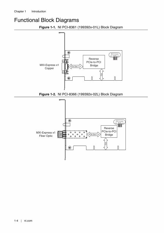
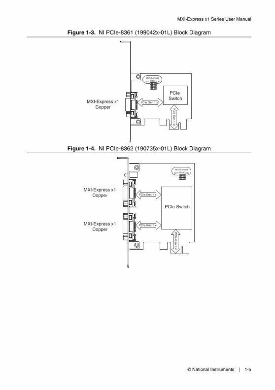
Functional Block DiagramsFigure 1-1. NI PCI-8361 (199392x-01L) Block Diagram
Figure 1-2. NI PCI-8366 (199392x-02L) Block Diagram
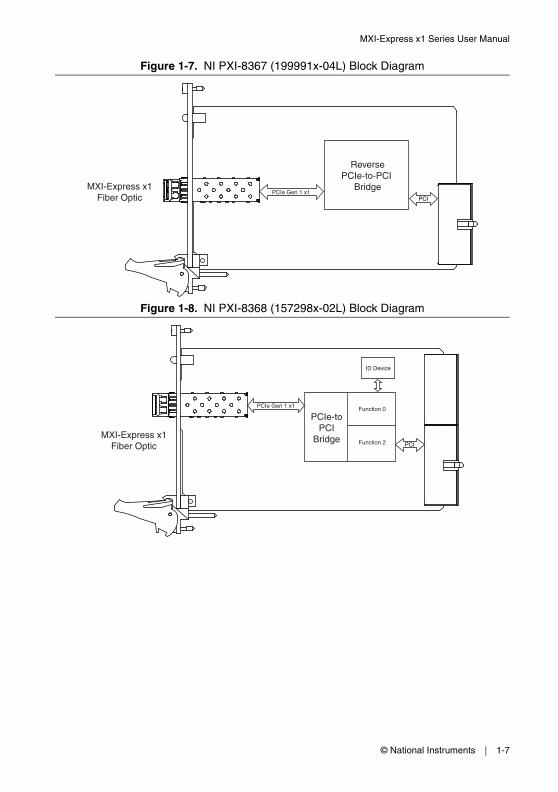
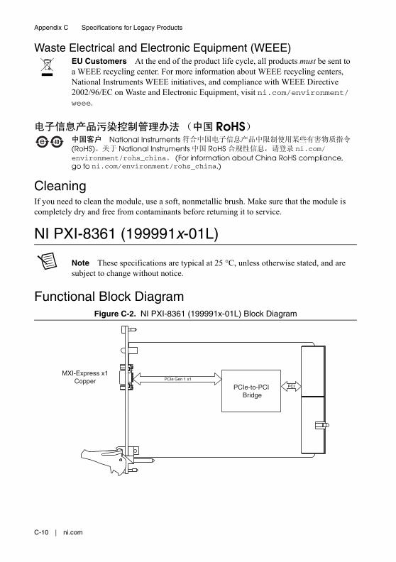
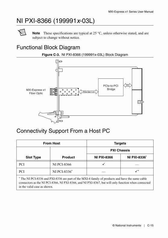
Figure 1-7. NI PXI-8367 (199991x-04L) Block Diagram
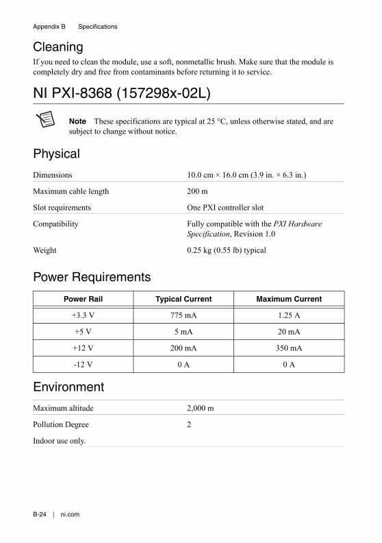
Figure 1-8. NI PXI-8368 (157298x-02L) Block Diagram
ReversePCIe-to-PCI
BridgePCI
MXI-Express x1Fiber Optic
PCIe Gen 1 x1
PCIe-toPCI
Bridge
ID Device
PCIe Gen 1 x1 Function 0
Function 2MXI-Express x1
Fiber Optic PCI
1-8 | ni.com
Chapter 1 Introduction
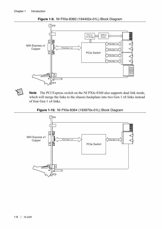
Figure 1-9. NI PXIe-8360 (194402x-01L) Block Diagram
Note The PCI Express switch on the NI PXIe-8360 also supports dual link mode, which will merge the links to the chassis backplane into two Gen 1 x8 links instead of four Gen 1 x4 links.
Figure 1-10. NI PXIe-8364 (193970x-01L) Block Diagram
Figure 1-11. NI ExpressCard-8360 (198266x-01L) Block Diagram
Note The NI ExpressCard-8360 (Part Number 192290x-01) has the same architecture as the 198266x-01L version, except that it uses a signal buffer instead of a PCI Express switch.
Basic MXI-Express x1 SystemsThe simplest MXI-Express x1 system can consist of a host board1 connected to a target board 1 installed in the controller slot of a chassis or integrated port of a chassis. Some example configurations are shown in Figure 1-12, and Table 1-2 lists all connectivity options going from a host PC to a chassis.
1 For more information refer to the Terminology section of Chapter 2, Getting Started.
PCIe Switch PCIe Gen 1 x1PCIe Gen 1 x1
MXI-Express x1Copper
1-10 | ni.com
Chapter 1 Introduction
Figure 1-12. Examples of Basic MXI-Express x1 Link Topologies
Note In this manual, whenever a PXI or PXI Express chassis is referenced, a CompactPCI or CompactPCI Express chassis could be used instead.
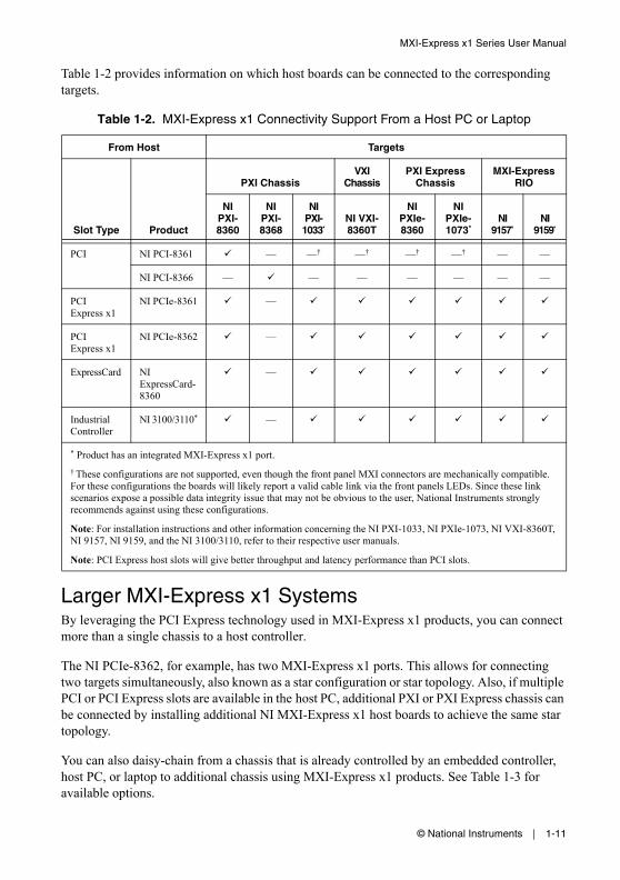
Table 1-2 provides information on which host boards can be connected to the corresponding targets.
Larger MXI-Express x1 SystemsBy leveraging the PCI Express technology used in MXI-Express x1 products, you can connect more than a single chassis to a host controller.
The NI PCIe-8362, for example, has two MXI-Express x1 ports. This allows for connecting two targets simultaneously, also known as a star configuration or star topology. Also, if multiple PCI or PCI Express slots are available in the host PC, additional PXI or PXI Express chassis can be connected by installing additional NI MXI-Express x1 host boards to achieve the same star topology.
You can also daisy-chain from a chassis that is already controlled by an embedded controller, host PC, or laptop to additional chassis using MXI-Express x1 products. See Table 1-3 for available options.
Table 1-2. MXI-Express x1 Connectivity Support From a Host PC or Laptop
From Host Targets
PXI ChassisVXI
ChassisPXI Express
ChassisMXI-Express
RIO
Slot Type Product
NI PXI-8360
NI PXI-8368
NI PXI-1033*
NI VXI-8360T
NI PXIe-8360
NI PXIe-1073*
NI 9157*
NI 9159*
PCI NI PCI-8361 — —† —† —† —† — —
NI PCI-8366 — — — — — — —
PCI Express x1
NI PCIe-8361 —
PCI Express x1
NI PCIe-8362 —
ExpressCard NI ExpressCard-8360
—
Industrial Controller
NI 3100/3110* —
* Product has an integrated MXI-Express x1 port.
† These configurations are not supported, even though the front panel MXI connectors are mechanically compatible. For these configurations the boards will likely report a valid cable link via the front panels LEDs. Since these link scenarios expose a possible data integrity issue that may not be obvious to the user, National Instruments strongly recommends against using these configurations.
Note: For installation instructions and other information concerning the NI PXI-1033, NI PXIe-1073, NI VXI-8360T, NI 9157, NI 9159, and the NI 3100/3110, refer to their respective user manuals.
Note: PCI Express host slots will give better throughput and latency performance than PCI slots.
1-12 | ni.com
Chapter 1 Introduction
Figure 1-13 shows how you can use MXI-Express x1 cards to connect multiple expansion chassis to a PC in a star or daisy-chain topology.
Figure 1-13. Example MXI-Express x1 System Expansion Topologies
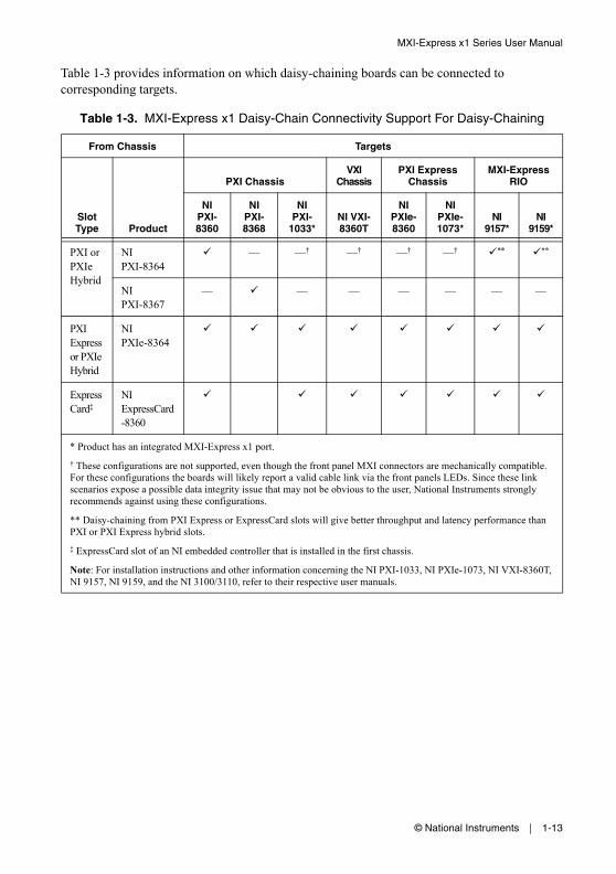
Table 1-3 provides information on which daisy-chaining boards can be connected to corresponding targets.
Table 1-3. MXI-Express x1 Daisy-Chain Connectivity Support For Daisy-Chaining
From Chassis Targets
PXI ChassisVXI
ChassisPXI Express
ChassisMXI-Express
RIO
Slot Type Product
NI PXI-8360
NI PXI-8368
NI PXI-
1033*NI VXI-8360T
NI PXIe-8360
NI PXIe-1073*
NI 9157*
NI 9159*
PXI or PXIe Hybrid
NI PXI-8364
— —† —† —† —† ** **
NI PXI-8367
— — — — — — —
PXI Express or PXIe Hybrid
NI PXIe-8364
ExpressCard‡
NI ExpressCard -8360
* Product has an integrated MXI-Express x1 port.
† These configurations are not supported, even though the front panel MXI connectors are mechanically compatible. For these configurations the boards will likely report a valid cable link via the front panels LEDs. Since these link scenarios expose a possible data integrity issue that may not be obvious to the user, National Instruments strongly recommends against using these configurations.
** Daisy-chaining from PXI Express or ExpressCard slots will give better throughput and latency performance than PXI or PXI Express hybrid slots.
‡ ExpressCard slot of an NI embedded controller that is installed in the first chassis.
Note: For installation instructions and other information concerning the NI PXI-1033, NI PXIe-1073, NI VXI-8360T, NI 9157, NI 9159, and the NI 3100/3110, refer to their respective user manuals.
This chapter explains what you will need to set up various MXI-Express x1 hardware configurations.
The products covered in this chapter are the NI PCI-8361, NI PCIe-8361/8362, NI PXI-8360/8364/8367/8368, NI PXIe-8360/8364, and NI ExpressCard-8360. For the remainder of this manual the term MXI-Express x1 product refers to any of these products.
Additional compatible products are included in subsequent tables, but are not covered in this manual.
TerminologyThe following terms may be used throughout this document:
• Host PC—A host computer with at least one of the following slot types available:
– PCI Express x1 or wider
– PCI
• Laptop—A portable laptop with the following slot types available:
– ExpressCard/34 or ExpressCard/54 slot with PCI Express support1
• Expansion Chassis—An expansion chassis of any of the following types:
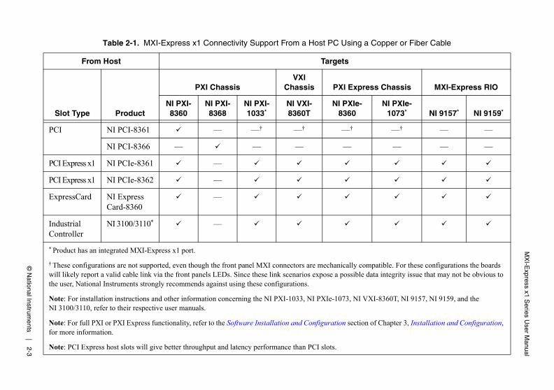
Table 2-1. MXI-Express x1 Connectivity Support From a Host PC Using a Copper or Fiber Cable
From Host Targets
PXI ChassisVXI
Chassis PXI Express Chassis MXI-Express RIO
Slot Type ProductNI PXI-8360
NI PXI-8368
NI PXI-1033*
NI VXI-8360T
NI PXIe-8360
NI PXIe-1073* NI 9157* NI 9159*
PCI NI PCI-8361 — —† —† —† —† — —
NI PCI-8366 — — — — — — —
PCI Express x1 NI PCIe-8361 —
PCI Express x1 NI PCIe-8362 —
ExpressCard NI Express Card-8360
—
Industrial Controller
NI 3100/3110* —
* Product has an integrated MXI-Express x1 port.
† These configurations are not supported, even though the front panel MXI connectors are mechanically compatible. For these configurations the boards will likely report a valid cable link via the front panels LEDs. Since these link scenarios expose a possible data integrity issue that may not be obvious to the user, National Instruments strongly recommends against using these configurations.
Note: For installation instructions and other information concerning the NI PXI-1033, NI PXIe-1073, NI VXI-8360T, NI 9157, NI 9159, and the NI 3100/3110, refer to their respective user manuals.
Note: For full PXI or PXI Express functionality, refer to the Software Installation and Configuration section of Chapter 3, Installation and Configuration, for more information.
Note: PCI Express host slots will give better throughput and latency performance than PCI slots.
2-4 | ni.com
Chapter 2 Getting Started
Connecting Additional Expansion Chassis to a System
Using a MXI-Express x1 Copper or Fiber CableRefer to the Terminology section for more detail on the items in this list.
Equipment Needed
Chassis (or embedded controller with ExpressCard slot) to daisy-chain from
Expansion chassis to daisy-chain to
MXI-Express x1 copper cable or MXI-Express x1 fiber cable
A MXI-Express x1 host board and target board that is appropriate for the host system slot and target chassis. Refer to Table 2-2 for more information.
Table 2-2. MXI-Express x1 Daisy-Chain Connectivity Support From a Chassis Using a Copper Cable
From Chassis Targets
PXI ChassisVXI
Chassis PXI Express Chassis MXI-Express RIO
Slot Type ProductNI PXI-8360
NI PXI-8368
NI PXI-1033*
NI VXI-8360T
NI PXIe-8360
NI PXIe-1073* NI 9157* NI 9159*
PXI or PXIe Hybrid
NI PXI-8364 — —† —† —† —† ** **
NI PXI-8367 — — — — — — —
PXI Express or PXIe Hybrid
NI PXIe-8364 —
ExpressCard‡ NI ExpressCard-8360 —
* Product has an integrated MXI-Express x1 port.
† These configurations are not supported, even though the front panel MXI connectors are mechanically compatible. For these configurations the boards will likely report a valid cable link via the front panels LEDs. Since these link scenarios expose a possible data integrity issue that may not be obvious to the user, National Instruments strongly recommends against using these configurations.
** Daisy-chaining from PXI Express or ExpressCard slots will give better throughput and latency performance than PXI or PXI Express hybrid slots.
‡ ExpressCard slot of an embedded controller that is installed in the chassis to be daisy-chained from.
Note: For installation instructions and other information concerning the NI PXI-1033, NI PXIe-1073, NI VXI-8360T, NI 9157, and NI 9159 refer to their respective user manuals.
Note: For full PXI or PXI Express functionality, refer to the Software Installation and Configuration section of Chapter 3, Installation and Configuration, for more information.
This chapter explains how to unpack, install, and configure the MXI-Express x1 hardware and software.
UnpackingYour MXI-Express x1 boards are shipped in antistatic packages to prevent electrostatic damage (ESD) to the devices. ESD can damage several components on the device.
Caution Never touch the exposed pins of connectors. Doing so may damage the device.
To avoid such damage in handling the device, take the following precautions:
• Ground yourself using a grounding strap or by holding a grounded object.
• Touch the antistatic package to a metal part of the computer chassis before removing the device from the package.
Remove the device from the package and inspect the device for loose components or any sign of damage. Notify NI if the device appears damaged in any way. Do not install a damaged device into a computer, laptop, PXI/CompactPCI, PXI Express/CompactPCI Express, CompactRIO, or VXI chassis.
Store the device in the antistatic envelope when not in use.
Hardware InstallationThe following are general instructions for installing the MXI-Express x1 cards. Consult your computer user manual or technical reference manual for specific instructions and warnings.
Installing an NI PCI-8361 or NI PCIe-8361/8362 Host CardComplete the following steps to install the NI PCI-8361 or NI PCIe-8361/8362 in your computer.
1. Power off your computer.
Caution To protect both yourself and the computer from electrical hazards, your computer should remain off until you finish installing all hardware as instructed.
3-2 | ni.com
Chapter 3 Installation and Configuration
2. Remove the top cover or access port to the PCI or PCI Express expansion slots.
3. Touch the metal part of the power supply case inside the computer to discharge any static electricity that might be on your clothes or body.
4. Unplug the computer and wait 30 seconds to allow the energy stored in the computer’s power supply to fully dissipate.
5. Select any available PCI slot for the NI PCI-8361 or PCI Express (x1 or wider) expansion slot for the NI PCIe-8361/8362.
6. Locate the metal bracket that covers the cut-out in the back panel of the computer for the slot you have selected. Remove and save the bracket-retaining screw and the bracket cover.
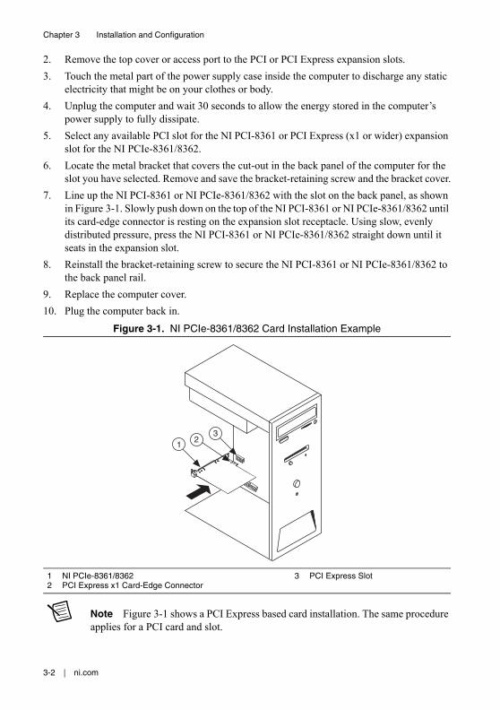
7. Line up the NI PCI-8361 or NI PCIe-8361/8362 with the slot on the back panel, as shown in Figure 3-1. Slowly push down on the top of the NI PCI-8361 or NI PCIe-8361/8362 until its card-edge connector is resting on the expansion slot receptacle. Using slow, evenly distributed pressure, press the NI PCI-8361 or NI PCIe-8361/8362 straight down until it seats in the expansion slot.
8. Reinstall the bracket-retaining screw to secure the NI PCI-8361 or NI PCIe-8361/8362 to the back panel rail.
9. Replace the computer cover.
10. Plug the computer back in.
Figure 3-1. NI PCIe-8361/8362 Card Installation Example
Note Figure 3-1 shows a PCI Express based card installation. The same procedure applies for a PCI card and slot.
1 NI PCIe-8361/83622 PCI Express x1 Card-Edge Connector
Installing the Low-Profile Bracket (Optional)To install the NI PCI-8361 or NI PCIe-8361 in a host computer that requires a low-profile height card, the front bracket must be replaced with the low-profile bracket included with your kit. Complete the following steps to replace the bracket.
NI PCI-8361 or NI PCIe-83611. Remove the standard height front bracket already installed on your NI PCI-8361 or
NI PCIe-8361 card by removing the two 4-40 × 3/16 inch Phillips head screws and the two 4-40 × 3/16 inch standoff screws that attach the bracket to the card, as shown in Figure 3-2. Set the screws aside to re-use when installing the low-profile bracket.
Figure 3-2. Removing the Standard Height Bracket from an NI PCI-8361
Note The NI PCI-8361 standard height bracket mounting tabs rest against the back side of the card. The NI PCIe-8361 standard height bracket mounting tabs rest against the front side of the card, which is the side upon which the cabled PCI Express connector rests.
2. Fit the low-profile bracket onto the NI PCI-8361 or NI PCIe-8361. Ensure the two mounting tabs on the low-profile bracket rest against the back side of the card and that the LED bulb is situated in the bracket’s LED display hole correctly, where applicable.
3. Align the mounting holes on the card with the threaded holes on the mounting tabs of the bracket. Insert the two 4-40 × 3/16 inch Phillips head screws from the front side of the card to attach the bracket.
4. Install the two 4-40 × 3/16 inch standoff screws to the front connector holes.
5. Tighten all screws to a maximum torque of 3.6 lb · in. (0.407 N · m).
1 4-40 × 3/16 inch Standoff Screws (x2)2 LED Display Hole3 Standard Height Bracket4 LED Bulb
5 4-40 × 3/16 inch Phillips Head Screws (x2)6 Cabled PCI Express Connector7 Front Side of Card8 Mounting Tab
4
1
8
3
7
2
65
3-4 | ni.com
Chapter 3 Installation and Configuration
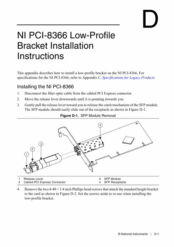
NI PCIe-83661. Disconnect the fiber optic cable from the cabled PCI Express connector.
2. Move the release lever downwards until it is pointing towards you.
3. Gently pull the release lever toward you to release the catch mechanism of the SFP module. The SFP module should easily slide out of the receptacle as shown in Figure 3-3.
Figure 3-3. SFP Module Removal
4. Remove the two 4-40 × 1/4 inch Phillips head screws that attach the standard height bracket to the card as shown in Figure 3-4. Set the screws aside to re-use when installing the low-profile bracket.
5. Remove the standard height bracket as shown in Figure 3-4.
Figure 3-4. Removing Bracket
1 Release Lever2 Cabled PCI Express Connector
3 SFP Module4 SFP Receptacle
1 Standard Height Bracket2 4-40 ×1/4 inch Phillips Head Screws (x2)
6. Fit the low-profile bracket onto the NI PCI-8366 by aligning the square cutout on the bracket with the SFP receptacle on the card. Ensure the two mounting tabs on the low-profile bracket rest against the back side of the card. The mounting holes are aligned with the threaded holes on the mounting tabs of the bracket, and the LED bulb is situated in the bracket display hole correctly.
7. Install the two Phillips screws from the front side of the card. Tighten each screw to a maximum torque of 3.6 lb · in. (0.407 N · m).
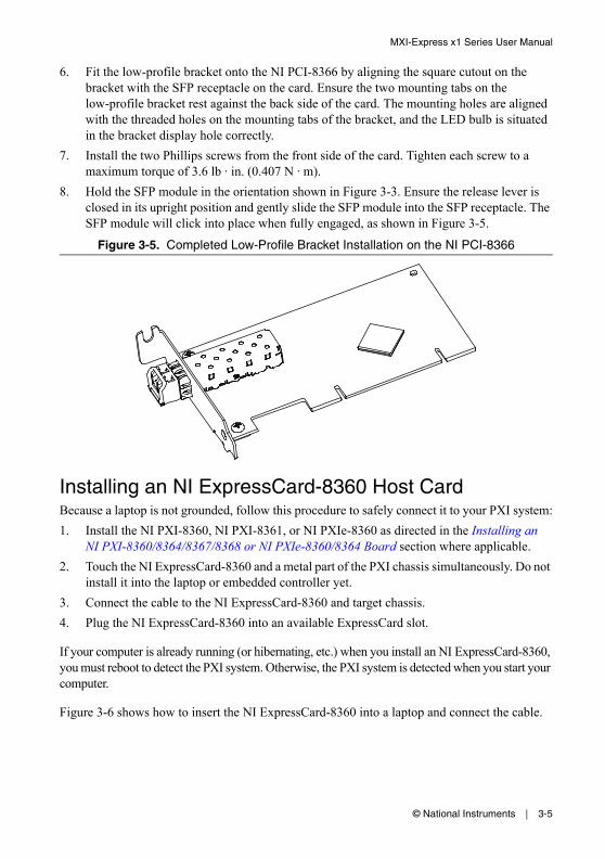
8. Hold the SFP module in the orientation shown in Figure 3-3. Ensure the release lever is closed in its upright position and gently slide the SFP module into the SFP receptacle. The SFP module will click into place when fully engaged, as shown in Figure 3-5.
Figure 3-5. Completed Low-Profile Bracket Installation on the NI PCI-8366
Installing an NI ExpressCard-8360 Host CardBecause a laptop is not grounded, follow this procedure to safely connect it to your PXI system:
1. Install the NI PXI-8360, NI PXI-8361, or NI PXIe-8360 as directed in the Installing an NI PXI-8360/8364/8367/8368 or NI PXIe-8360/8364 Board section where applicable.
2. Touch the NI ExpressCard-8360 and a metal part of the PXI chassis simultaneously. Do not install it into the laptop or embedded controller yet.
3. Connect the cable to the NI ExpressCard-8360 and target chassis.
4. Plug the NI ExpressCard-8360 into an available ExpressCard slot.
If your computer is already running (or hibernating, etc.) when you install an NI ExpressCard-8360, you must reboot to detect the PXI system. Otherwise, the PXI system is detected when you start your computer.
Figure 3-6 shows how to insert the NI ExpressCard-8360 into a laptop and connect the cable.
3-6 | ni.com
Chapter 3 Installation and Configuration
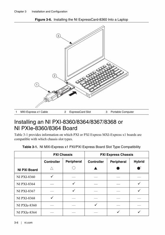
Figure 3-6. Installing the NI ExpressCard-8360 Into a Laptop
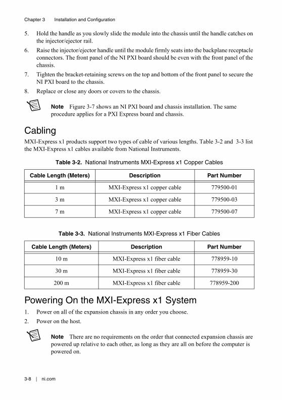
Installing an NI PXI-8360/8364/8367/8368 or NI PXIe-8360/8364 BoardTable 3-1 provides information on which PXI or PXI Express MXI-Express x1 boards are compatible with which chassis slot types.
Note For this section, all of the above products will be referred to as an “NI PXI board.”
Complete the following steps to install the NI PXI board into your PXI or PXI Express chassis.
1. Power off your PXI or PXI Express chassis, and leave it plugged in. The power cord grounds the chassis and protects it from ESD.
Caution To protect both yourself and the chassis from electrical hazards, leave the chassis off until you finish installing the NI PXI board.
2. Remove or open any doors or covers blocking access to the slot in which you intend to install the NI PXI board.
3. Touch a metal part of the chassis to discharge any static electricity that might be on your clothes or body.
4. Make sure the injector/ejector handle is in its downward position. Be sure to remove all connector packaging and protective caps from retaining screws on the module. Align the NI PXI board with the card guides on the top and bottom of the chassis slot.
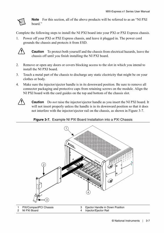
Caution Do not raise the injector/ejector handle as you insert the NI PXI board. It will not insert properly unless the handle is in its downward position so that it does not interfere with the injector/ejector rail on the chassis, as shown in Figure 3-7.
Figure 3-7. Example NI PXI Board Installation into a PXI Chassis
1 PXI/CompactPCI Chassis2 NI PXI Board
3 Ejector Handle in Down Position4 Injector/Ejector Rail
3
1
2
4
3-8 | ni.com
Chapter 3 Installation and Configuration
5. Hold the handle as you slowly slide the module into the chassis until the handle catches on the injector/ejector rail.
6. Raise the injector/ejector handle until the module firmly seats into the backplane receptacle connectors. The front panel of the NI PXI board should be even with the front panel of the chassis.
7. Tighten the bracket-retaining screws on the top and bottom of the front panel to secure the NI PXI board to the chassis.
8. Replace or close any doors or covers to the chassis.
Note Figure 3-7 shows an NI PXI board and chassis installation. The same procedure applies for a PXI Express board and chassis.
CablingMXI-Express x1 products support two types of cable of various lengths. Table 3-2 and 3-3 list the MXI-Express x1 cables available from National Instruments.
Powering On the MXI-Express x1 System1. Power on all of the expansion chassis in any order you choose.
2. Power on the host.
Note There are no requirements on the order that connected expansion chassis are powered up relative to each other, as long as they are all on before the computer is powered on.
Table 3-2. National Instruments MXI-Express x1 Copper Cables
Cable Length (Meters) Description Part Number
1 m MXI-Express x1 copper cable 779500-01
3 m MXI-Express x1 copper cable 779500-03
7 m MXI-Express x1 copper cable 779500-07
Table 3-3. National Instruments MXI-Express x1 Fiber Cables
3. Observe the LED status on the NI PCI-8361, NI PCIe-8361/8362, NI PXI-8360/8364/8367/8368, and NI PXIe-8360/8364/8367/8368 where applicable. A properly connected and powered up system should display a valid link and power status on all of these boards once the host PC is powered on. Refer to the LED Indicators section for more information.
Typical PCI-PCI bridges are used to add PCI devices to a PCI hierarchy in which all the bridges and devices are contained within a single chassis. Because of this, BIOSes and operating systems make the assumption that all PCI devices in the entire hierarchy will be available as soon as code execution begins at power-up time. This assumption means that all of the expansion chassis must be turned on before the host PC for the BIOS and OS to correctly configure a MXI-Express system.
Note In some cases where there is an invalid MXI-Express x1 connection, some boards may report a valid link while others do not. It is important to observe a valid link status across all connected MXI-Express x1 boards when the host is powered on to ensure a valid configuration.
Powering Off the MXI-Express x1 SystemBecause operating systems and drivers commonly make the assumption that PCI devices will be present in the system from power-up to power-down, it is important not to power off the expansion chassis until after the host PC is powered off. Powering off the expansion chassis while the host is still on can cause crashes or hangs. However, once the host PC is powered off, the order that the expansion chassis are powered off is not important.
LED IndicatorsThe LEDs on MXI-Express x1 cards provide status information about power supplies and link state. The NI PCI-8361, NI PXI-8364/8367, and NI PXIe-8364 all have one tri-color LED on the panel, indicating power and link status. The NI PCIe-8362 has two tri-color LEDs on the panel, indicating power and link status for each port. The NI PXI-8360/8368 and NI PXIe-8360 have two LEDs, one for power supply status and one for link state.
Note In some cases where there is an invalid MXI-Express x1 connection, some boards may report a valid link while others do not. It is important to observe a valid link status across all connected MXI-Express x1 boards when the host is powered on to ensure a valid configuration.
3-10 | ni.com
Chapter 3 Installation and Configuration
Refer to Figure 3-8 for onboard LED locations.
Figure 3-8. NI PXIe-8364 (193970x-01L) Onboard LED Locations
Link Good LEDs—LEDs that indicate a successful cable link (LED 0) and backplane link (LED 4).
Table 3-4. LED Status Descriptions of MXI-Express x1 Products
Board LED Color Meaning
NI PCI-8361 (199392x-01L)
NI PCIe-8362 (190735x-01L)
NI PXI-8364 (199991x-02L)
NI PXI-8367 (199991x-04L)
NI PXIe-8364 (193970x-01L)
PWR/LINK Off Power is off
Blinking Red Power is out of spec
Solid Amber Power is within spec; no link to chassis
Solid Green Power is within spec; link established
Link Activity LEDs—LEDs that indicate link activity on the cable link (LED 0) and the backplane link (LED 4).
The NI PXIe-8360 also has a vertical column of 16 LEDs on the back side of the card near the front connector, as shown in Figure 3-9. These LEDs provide additional information about the link status of the PCI Express lanes on the module to the backplane. Each group of four LEDs corresponds to one of the four PCI Express links to the backplane.
Figure 3-9. NI PXIe-8360 Back Side LED Locations
Note If you are using a chassis (such as the NI PXIe-1062) that directly links the PXI Express board, the LEDs to that slot will not illuminate until you have a PXI Express board installed and linked.
If you are using the NI PXIe-1062 chassis, you will notice that the last group of LEDs has an LED (PORT 3) illuminated even if no boards are populated in the slots. Since the NI PXIe-1062 uses the last link for a PCI Express to PCI bridge for PXI communication, this link should always be active. Different chassis topologies will give different default behaviors. Contact your chassis’ manufacturer for more information on your chassis’ topology.
1 Back Panel LEDs
1
3-12 | ni.com
Chapter 3 Installation and Configuration
Software Installation and Configuration
InstallationMXI-Express x1 is based on PCI Express technology, using PCI Express switches and/or bridges to enable control of a PXI or PXI Express chassis from a PC or laptop with an available PCI, PCI Express, or ExpressCard slot. This technology will be recognized as a collection of PCI-to-PCI bridges to the operating system, and should automatically have CompactPCI support without any additional software.
Note For full PXI/PXI Express functionality such as chassis and controller identification, trigger routing, and slot detection, install the PXI Platform Services software included with your kit. This software also can be found at ni.com/updates by searching for PXI Platform Services.
For operating system support, refer to the KnowledgeBase 53399AQ7, PXI Platform Services Operating System Support, at ni.com/kb.
Configuring Your System
Note The following requires the PXI Platform Services software and Measurement & Automation Explorer (MAX), included on your PXI Platform Services CD or your driver CD.
For information on configuring your system in MAX, open MAX and navigate to Help»Help Topics»PXI.
This appendix lists common questions related to the use of NI MXI-Express x1 products.
General HardwareDoes NI offer a chassis with the MXI-Express x1 controller integrated?
Yes. Refer to Table 2-1, MXI-Express x1 Connectivity Support From a Host PC Using a Copper or Fiber Cable, for more information.
What connectors does the MXI-Express x1 copper cable use?
The MXI-Express x1 copper cables use Molex TDP™ connectors. For more information about these connectors, visit Molex at www.molex.com and search for TDP.
Will my PC or laptop model work with MXI-Express x1 products?
It will depend on the robustness of the BIOS in your PC or laptop. In most cases, the BIOS should be able to enumerate the bridge resources that the MXI products require for operation, especially for smaller MXI system configurations. For more information, refer to the NI Developer Zone article, Tips to Help You Successfully Use NI MXI-Express Controllers, at ni.com/zone.
MXI-3 and MXI-4 to MXI-Express x1 Upgrade QuestionsWhat are some of the improvements from MXI-3 and MXI-4 to MXI-Express x1?
MXI-Express x1 incorporates the latest technology to include:
• Support for PCI, PCI Express, and ExpressCard slots.
• Laptop or desktop control of PXI, PXI Express, VXI, and CompactRIO chassis.
• Improved error correction and handling for noisy or harsh environments.
• Improved mechanical connectivity.
• Improved performance.
• Support for two chassis from a single card in the host PC.
• Lower cost.
A-2 | ni.com
Appendix A Common Questions
Can I connect a MXI-3 or MXI-4 board to a MXI-Express x1 board?
No. MXI-3, MXI-4, and MXI-Express x1 boards use different cable connectors and protocols in most cases and cannot be mixed. This is because the board-to-board communication protocols differ.
For example, an NI PCI-8336, which is a MXI-4 product, will not work with an NI PXI-8368 even though the connectors are the same. Refer to Table 1-2 in Chapter 1, Introduction, for more information on connectivity support.
Can I use a MXI-3, MXI-4, and MXI-Express x1 kit in the same multichassis PXI system?
Yes. Different MXI kits can be intermixed to connect multiple chassis together. A kit is defined as a host and target board that both support the same link type like MXI-3, MXI-4, or MXI-Express x1. As mentioned previously, an individual MXI-3 or MXI-4 board will not link correctly to a MXI-Express x1 board.
MXI-3 and MXI-4 systems required the use of a specific boot ordering. Is this a requirement with MXI-Express x1?
Yes. The requirements of the PCI bus still mandate that you must power on secondary PXI chassis before powering on the host PC when using MXI-Express x1.
With MXI-3 and several chassis connected in series (daisy-chain configuration), you were required to power on the chassis in order starting with the chassis at the end of the chain and move towards the host controller. Now with MXI-Express x1, multiple chassis may be connected in parallel and can be powered on in any order, except that you need to ensure that the last component powered on is the host PC.
For more details, refer to the Powering On the MXI-Express x1 System section of Chapter 3, Installation and Configuration.
MXI-3 required optimization software. Does MXI-Express x1 require the same?
No. The necessary optimization is now done automatically by the MXI-Express x1 hardware.
Can I use MXI-Express x1 products in place of MXI-4?
Yes. There are products that offer the same PCI slot-to-PXI chassis connectivity as MXI-4 with a few differences, as shown in Table A-1.
Table A-1. Feature Comparison Between MXI-4 and Comparable MXI-Express x1 Products
FeaturesMXI-4 Copper (PCI/PXI-8331)
MXI-Express x1 Copper (PCI/PXI-8360, PXI-8364)
Maximum Cable Length 10 m 7 m
PXI Modules Interchangeable Between PXI Controller or Peripheral Slots
Yes No*
PXI Hybrid Slot Compatibility† No Yes
PCI Slot Voltage Compatibility Universal Universal
PXI Slot Voltage Compatibility 5 V‡ Universal
Sustained Throughput (MB/s) Up to 78** Up to 100**
Cable Connector Type 4-pin serial D-Sub 18-pin PCI Express x1 D-Sub
LEDs for Power/Link 2/2 1/2/1
LEDs for Activity 2/2 0/0/0
PCI Express Slot to PXI Link Capability***
No Yes
ExpressCard Slot to PXI Link Capability***
No Yes
Low-Profile Height for PCI Board No Yes
* Unlike MXI-4, the MXI-Express-based PXI controller modules are different from the PXI peripheral modules used to daisy-chain to subsequent chassis.† With hybrid slot support, you can connect an expansion chassis to a PXI Express chassis that contains PXI hybrid slots.** Actual throughput performance varies depending on the system setup and composition.‡ Universal options for copper and fiber-optic MXI-4 products are available upon request.*** With the copper MXI-Express PXI modules, you can control a PXI chassis from a PCI Express or ExpressCard slot in your host computer using the NI PCIe-8361, NI PCIe-8362, or NI ExpressCard-8360.
A-4 | ni.com
Appendix A Common Questions
Note In addition to these differences, there is one additional PCI bridge across the host and target link compared to a MXI-4 link which will be visible to the operating system (OS). If you replace any MXI-4 compatible products with MXI-Express x1 products, the additional bridge will cause the OS to rediscover all devices that were part of the existing MXI system. This causes the OS to change the reference names used by driver software. The result is that all device resource names that are part of the MXI system will change, such as the names used in Measurement & Automation Explorer (MAX) and VISA.
General SoftwareUnder which operating systems will MXI-Express x1 products work?
MXI-Express x1 will be recognized as a collection of PCI-to-PCI bridges to the majority of operating systems. It should automatically have CompactPCI Express support with most systems like Windows, Macintosh OS X, Linux, and Solaris. For full PXI Express functionality, PXI Platform Services software is required. Refer to the Software Installation and Configuration section of Chapter 3, Installation and Configuration, for more information.
What software is required to use my MXI-Express x1 kit?
For Windows and LabVIEW RT, the required software is included as part of the latest version of NI PXI Platform Services included with your kit. The software for your MXI-Express x1 controller enhances the product, allowing you to view information about the organization of your PXI system, gain access to the trigger routing capabilities of the PXI or PXI Express chassis, and programmatically retrieve data about the chassis and modules you have installed.
Please refer to the following KnowledgeBase for the current supported operating systems for NI PXI Platform Services:
KB 53399AQ7: PXI Platform Services Operating System Support
If your operating system is not supported by PXI Platform Services, you can still use MXI-Express x1 as a PCI Express expansion solution. However, access to features such as chassis and controller identification, trigger routing, and slot detection will be lost.
This appendix lists the system specifications for the following products only:
• NI PCI-8361 (199392x-01L)
• NI PCI-8366 (199392x-02L)
• NI PCIe-8361 (199042x-01L)
• NI PCIe-8362 (190735x-01L)
• NI PXI-8360 (191373x-01)
• NI PXI-8364 (199991x-02L)
• NI PXI-8367 (199991x-04L)
• NI PXI-8368 (157298x-02L)
• NI PXIe-8360 (194402x-01L)
• NI PXIe-8364 (193970x-01L)
• NI ExpressCard-8360 (198266x-01L)
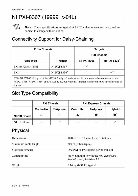
Note The model numbers listed below are followed by their specific NI assembly numbers in parentheses. x denotes all letter revisions of the assembly. Ensure the specifications of interest match the NI assembly number that is printed on either the front or back side of the board.
For specifications on previous generations of products, refer to Appendix C, Specifications for Legacy Products.
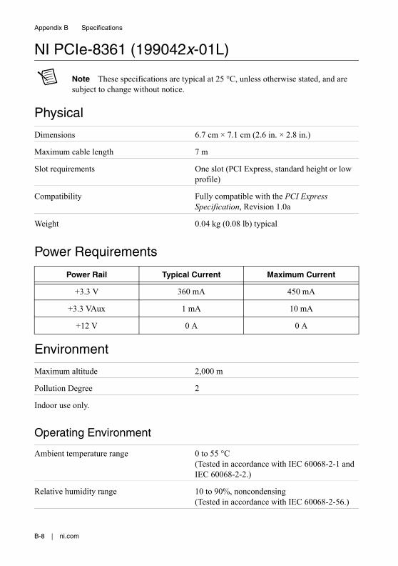
NI PCI-8361 (199392x-01L)
Note These specifications are typical at 25 °C, unless otherwise stated, and are subject to change without notice.
Physical
Dimensions 6.3 cm × 12.1 cm (2.48 in. × 4.76 in.)
Maximum cable length 7 m
Slot requirements One PCI slot (standard height or low profile)
B-2 | ni.com
Appendix B Specifications
Compatibility Fully compatible with the PCI Specification, Revision 3.0
Weight 0.05 kg (0.11 lb) typical
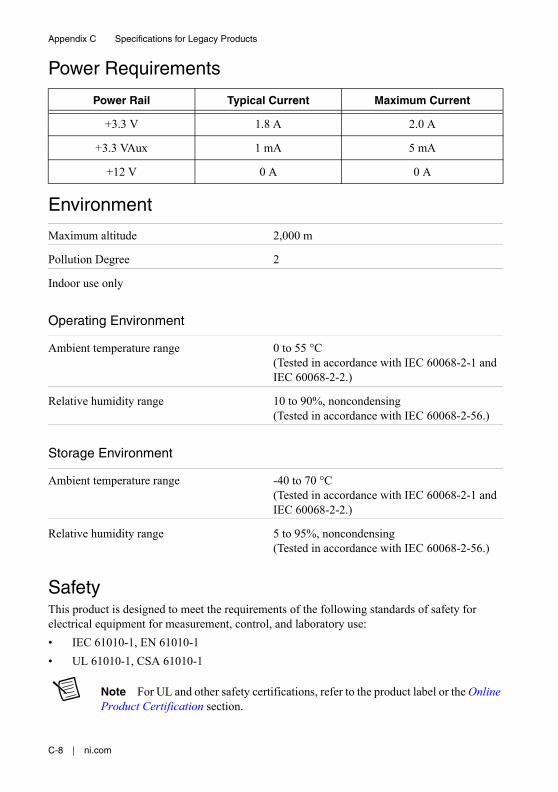
Power Requirements
Environment
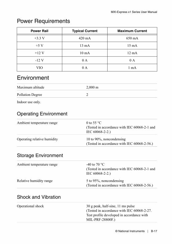
Maximum altitude 2,000 m
Pollution Degree 2
Indoor use only.
Operating Environment
Ambient temperature range 0 to 55 °C(Tested in accordance with IEC 60068-2-1 and IEC 60068-2-2.)
Operating relative humidity 10 to 90%, noncondensing (Tested in accordance with IEC 60068-2-56.)
Storage Environment
Ambient temperature range -20 to 70 °C(Tested in accordance with IEC 60068-2-1 and IEC 60068-2-2.)
Relative humidity range 5 to 95%, noncondensing (Tested in accordance with IEC 60068-2-56.)
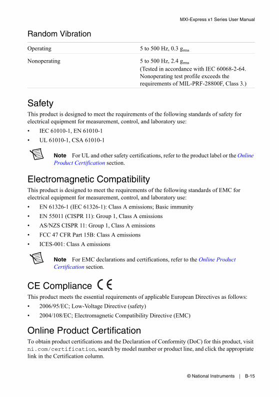
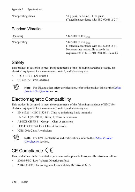
SafetyThis product is designed to meet the requirements of the following standards of safety for electrical equipment for measurement, control, and laboratory use:
• IEC 61010-1, EN 61010-1
• UL 61010-1, CSA 61010-1
Note For UL and other safety certifications, refer to the product label or the Online Product Certification section.
Electromagnetic CompatibilityThis product is designed to meet the requirements of the following standards of EMC for electrical equipment for measurement, control, and laboratory use:
• EN 61326-1 (IEC 61326-1): Class A emissions; Basic immunity
• EN 55011 (CISPR 11): Group 1, Class A emissions
• AS/NZS CISPR 11: Group 1, Class A emissions
• FCC 47 CFR Part 15B: Class A emissions
• ICES-001: Class A emissions
Note For EMC declarations and certifications, refer to the Online Product Certification section.
CE ComplianceThis product meets the essential requirements of applicable European Directives as follows:
Online Product CertificationTo obtain product certifications and the Declaration of Conformity (DoC) for this product, visit ni.com/certification, search by model number or product line, and click the appropriate link in the Certification column.
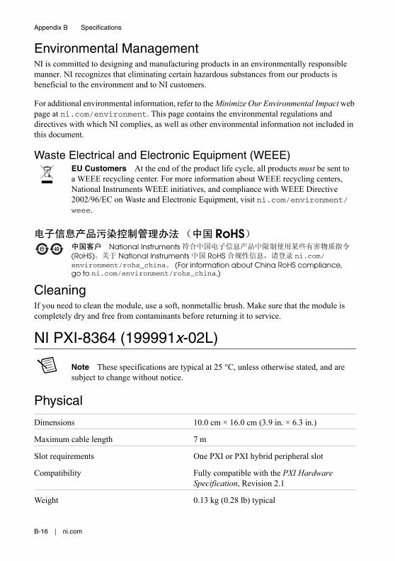
Environmental ManagementNI is committed to designing and manufacturing products in an environmentally responsible manner. NI recognizes that eliminating certain hazardous substances from our products is beneficial to the environment and to NI customers.
For additional environmental information, refer to the Minimize Our Environmental Impact web page at ni.com/environment. This page contains the environmental regulations and
B-4 | ni.com
Appendix B Specifications
directives with which NI complies, as well as other environmental information not included in this document.
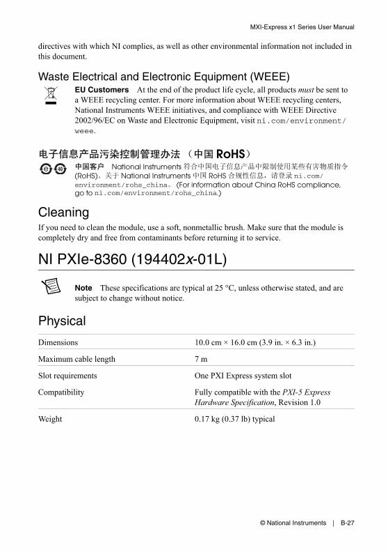
Waste Electrical and Electronic Equipment (WEEE)EU Customers At the end of the product life cycle, all products must be sent to a WEEE recycling center. For more information about WEEE recycling centers, National Instruments WEEE initiatives, and compliance with WEEE Directive 2002/96/EC on Waste and Electronic Equipment, visit ni.com/environment/weee.
CleaningIf you need to clean the module, use a soft, nonmetallic brush. Make sure that the module is completely dry and free from contaminants before returning it to service.
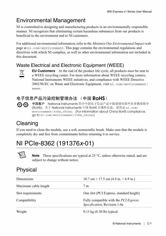
NI PCI-8366 (199392x-02L)
Note These specifications are typical at 25 °C, unless otherwise stated, and are subject to change without notice.
Note For instructions to install the low-profile bracket, refer to Appendix D,NI PCI-8366 Low-Profile Bracket Installation Instructions.
Connectivity Support
From Host Targets
Slot Type Product
PXI Chassis
NI PXI-8366 NI PXI-8336*
PCI NI PCI-8366 —
PCI NI PCI-8336* — *
* The NI PCI-8336 and PXI-8336 are part of the MXI-4 family of products and have the same cable connectors as the NI PCI-8366, NI PXI-8366, and NI PXI-8367, but will only function when connected in the valid case as shown.
RoHSNational Instruments
(RoHS) National Instruments RoHS ni.com/environment/rohs_china (For information about China RoHS compliance, go to ni.com/environment/rohs_china.)
Slot requirements One PCI slot (standard height or low profile)
Compatibility Fully compatible with the PCI Specification, Revision 3.0
Weight 0.07 kg (0.15 lb) typical
LED Status Descriptions
Power Requirements
Environment
Maximum altitude 2,000 m
Pollution Degree 2
Indoor use only.
LED Color Meaning
PWR/LINK Off Power is off
Blinking Red Power is out of spec
Solid Amber Power is within spec; no link to chassis
Solid Green Power is within spec; link established
Power Rail Typical Current Maximum Current
+3.3 V 155 mA 250 mA
+5 V 265 mA 400 mA
VIO 0 A 1 mA
B-6 | ni.com
Appendix B Specifications
Operating Environment
Ambient temperature range 0 to 55 °C(Tested in accordance with IEC 60068-2-1 and IEC 60068-2-2.)
Operating relative humidity 10 to 90%, noncondensing (Tested in accordance with IEC 60068-2-56.)
Storage Environment
Ambient temperature range -20 to 70 °C(Tested in accordance with IEC 60068-2-1 and IEC 60068-2-2.)
Relative humidity range 5 to 95%, noncondensing (Tested in accordance with IEC 60068-2-56.)
SafetyThis product is designed to meet the requirements of the following standards of safety for electrical equipment for measurement, control, and laboratory use:
• IEC 61010-1, EN 61010-1
• UL 61010-1, CSA 61010-1
Note For UL and other safety certifications, refer to the product label or the Online Product Certification section.
Electromagnetic CompatibilityThis product is designed to meet the requirements of the following standards of EMC for electrical equipment for measurement, control, and laboratory use:
• EN 61326-1 (IEC 61326-1): Class A emissions; Basic immunity
• EN 55011 (CISPR 11): Group 1, Class A emissions
• AS/NZS CISPR 11: Group 1, Class A emissions
• FCC 47 CFR Part 15B: Class A emissions
• ICES-001: Class A emissions
Note For EMC declarations and certifications, refer to the Online Product Certification section.
Online Product CertificationTo obtain product certifications and the Declaration of Conformity (DoC) for this product, visit ni.com/certification, search by model number or product line, and click the appropriate link in the Certification column.
Environmental ManagementNI is committed to designing and manufacturing products in an environmentally responsible manner. NI recognizes that eliminating certain hazardous substances from our products is beneficial to the environment and to NI customers.
For additional environmental information, refer to the Minimize Our Environmental Impact web page at ni.com/environment. This page contains the environmental regulations and directives with which NI complies, as well as other environmental information not included in this document.
Waste Electrical and Electronic Equipment (WEEE)EU Customers At the end of the product life cycle, all products must be sent to a WEEE recycling center. For more information about WEEE recycling centers, National Instruments WEEE initiatives, and compliance with WEEE Directive 2002/96/EC on Waste and Electronic Equipment, visit ni.com/environment/weee.
CleaningIf you need to clean the module, use a soft, nonmetallic brush. Make sure that the module is completely dry and free from contaminants before returning it to service.
RoHSNational Instruments
(RoHS) National Instruments RoHS ni.com/environment/rohs_china (For information about China RoHS compliance, go to ni.com/environment/rohs_china.)
B-8 | ni.com
Appendix B Specifications
NI PCIe-8361 (199042x-01L)
Note These specifications are typical at 25 °C, unless otherwise stated, and are subject to change without notice.
Physical
Dimensions 6.7 cm × 7.1 cm (2.6 in. × 2.8 in.)
Maximum cable length 7 m
Slot requirements One slot (PCI Express, standard height or low profile)
Compatibility Fully compatible with the PCI Express Specification, Revision 1.0a
Weight 0.04 kg (0.08 lb) typical
Power Requirements
Environment
Maximum altitude 2,000 m
Pollution Degree 2
Indoor use only.
Operating Environment
Ambient temperature range 0 to 55 °C(Tested in accordance with IEC 60068-2-1 and IEC 60068-2-2.)
Relative humidity range 10 to 90%, noncondensing (Tested in accordance with IEC 60068-2-56.)
Ambient temperature range -20 to 70 °C(Tested in accordance with IEC 60068-2-1 and IEC 60068-2-2.)
Relative humidity range 5 to 95%, noncondensing (Tested in accordance with IEC 60068-2-56.)
SafetyThis product is designed to meet the requirements of the following standards of safety for electrical equipment for measurement, control, and laboratory use:
• IEC 61010-1, EN 61010-1
• UL 61010-1, CSA 61010-1
Note For UL and other safety certifications, refer to the product label or the Online Product Certification section.
Electromagnetic CompatibilityThis product is designed to meet the requirements of the following standards of EMC for electrical equipment for measurement, control, and laboratory use:
• EN 61326-1 (IEC 61326-1): Class A emissions; Basic immunity
• EN 55011 (CISPR 11): Group 1, Class A emissions
• AS/NZS CISPR 11: Group 1, Class A emissions
• FCC 47 CFR Part 15B: Class A emissions
• ICES-001: Class A emissions
Note For EMC declarations and certifications, refer to the Online Product Certification section.
CE ComplianceThis product meets the essential requirements of applicable European Directives as follows:
Online Product CertificationTo obtain product certifications and the Declaration of Conformity (DoC) for this product, visit ni.com/certification, search by model number or product line, and click the appropriate link in the Certification column.
B-10 | ni.com
Appendix B Specifications
Environmental ManagementNI is committed to designing and manufacturing products in an environmentally responsible manner. NI recognizes that eliminating certain hazardous substances from our products is beneficial to the environment and to NI customers.
For additional environmental information, refer to the Minimize Our Environmental Impact web page at ni.com/environment. This page contains the environmental regulations and directives with which NI complies, as well as other environmental information not included in this document.
Waste Electrical and Electronic Equipment (WEEE)EU Customers At the end of the product life cycle, all products must be sent to a WEEE recycling center. For more information about WEEE recycling centers, National Instruments WEEE initiatives, and compliance with WEEE Directive 2002/96/EC on Waste and Electronic Equipment, visit ni.com/environment/weee.
CleaningIf you need to clean the module, use a soft, nonmetallic brush. Make sure that the module is completely dry and free from contaminants before returning it to service.
NI PCIe-8362 (190735x-01L)
Note These specifications are typical at 25 °C, unless otherwise stated, and are subject to change without notice.
Physical
Dimensions 9.93 cm × 7.11 cm (3.91 in. × 2.8 in.)
Maximum cable length 7 m
Slot requirements One slot (PCI Express, standard height)
Compatibility Fully compatible with the PCI Express Specification, Revision 1.0a
Weight 0.05 kg (0.12 lb) typical
RoHSNational Instruments
(RoHS) National Instruments RoHS ni.com/environment/rohs_china (For information about China RoHS compliance, go to ni.com/environment/rohs_china.)
Ambient temperature range 0 to 55 °C(Tested in accordance with IEC 60068-2-1 and IEC 60068-2-2.)
Operating relative humidity 10 to 90%, noncondensing (Tested in accordance with IEC 60068-2-56.)
Storage Environment
Ambient temperature range -40 to 70 °C (Tested in accordance with IEC 60068-2-1 and IEC 60068-2-2.)
Storage relative humidity 5 to 95%, noncondensing (Tested in accordance with IEC 60068-2-56.)
SafetyThis product is designed to meet the requirements of the following standards of safety for electrical equipment for measurement, control, and laboratory use:
• IEC 61010-1, EN 61010-1
• UL 61010-1, CSA 61010-1
Note For UL and other safety certifications, refer to the product label or the Online Product Certification section.
Power Rail Typical Current Maximum Current
+3.3 V 580 mA 1.040 A
+3.3 VAux 10 mA 50 mA
+12 V 0 A 0 A
B-12 | ni.com
Appendix B Specifications
Electromagnetic CompatibilityThis product is designed to meet the requirements of the following standards of EMC for electrical equipment for measurement, control, and laboratory use:
• EN 61326-1 (IEC 61326-1): Class A emissions; Basic immunity
• EN 55011 (CISPR 11): Group 1, Class A emissions
• AS/NZS CISPR 11: Group 1, Class A emissions
• FCC 47 CFR Part 15B: Class A emissions
• ICES-001: Class A emissions
Note For EMC declarations and certifications, refer to the Online Product Certification section.
CE ComplianceThis product meets the essential requirements of applicable European Directives as follows:
Online Product CertificationTo obtain product certifications and the Declaration of Conformity (DoC) for this product, visit ni.com/certification, search by model number or product line, and click the appropriate link in the Certification column.
Environmental ManagementNI is committed to designing and manufacturing products in an environmentally responsible manner. NI recognizes that eliminating certain hazardous substances from our products is beneficial to the environment and to NI customers.
For additional environmental information, refer to the Minimize Our Environmental Impact web page at ni.com/environment. This page contains the environmental regulations and directives with which NI complies, as well as other environmental information not included in this document.
Waste Electrical and Electronic Equipment (WEEE)EU Customers At the end of the product life cycle, all products must be sent to a WEEE recycling center. For more information about WEEE recycling centers, National Instruments WEEE initiatives, and compliance with WEEE Directive 2002/96/EC on Waste and Electronic Equipment, visit ni.com/environment/weee.
CleaningIf you need to clean the module, use a soft, nonmetallic brush. Make sure that the module is completely dry and free from contaminants before returning it to service.
NI PXI-8360 (191373x-01)
Note These specifications are typical at 25 °C, unless otherwise stated, and are subject to change without notice.
Physical
Dimensions 10.0 cm × 16.0 cm (3.9 in. × 6.3 in.)
Maximum cable length 7 m
Slot requirements One PXI controller slot
Compatibility Fully compatible with the PXI Hardware Specification, Revision 1.0
Weight 0.25 kg (0.55 lb) typical
RoHSNational Instruments
(RoHS) National Instruments RoHS ni.com/environment/rohs_china (For information about China RoHS compliance, go to ni.com/environment/rohs_china.)
B-14 | ni.com
Appendix B Specifications
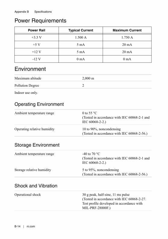
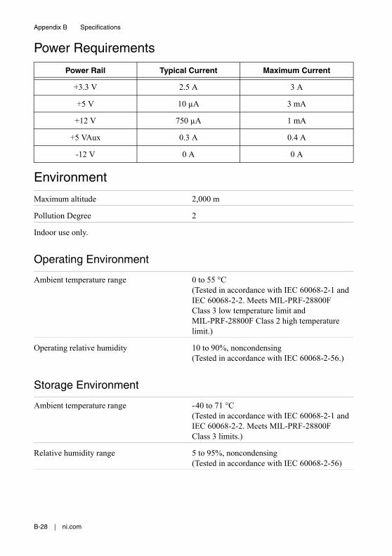
Power Requirements
Environment
Maximum altitude 2,000 m
Pollution Degree 2
Indoor use only.
Operating Environment
Ambient temperature range 0 to 55 °C(Tested in accordance with IEC 60068-2-1 and IEC 60068-2-2.)
Operating relative humidity 10 to 90%, noncondensing (Tested in accordance with IEC 60068-2-56.)
Storage Environment
Ambient temperature range -40 to 70 °C (Tested in accordance with IEC 60068-2-1 and IEC 60068-2-2.)
Storage relative humidity 5 to 95%, noncondensing (Tested in accordance with IEC 60068-2-56.)
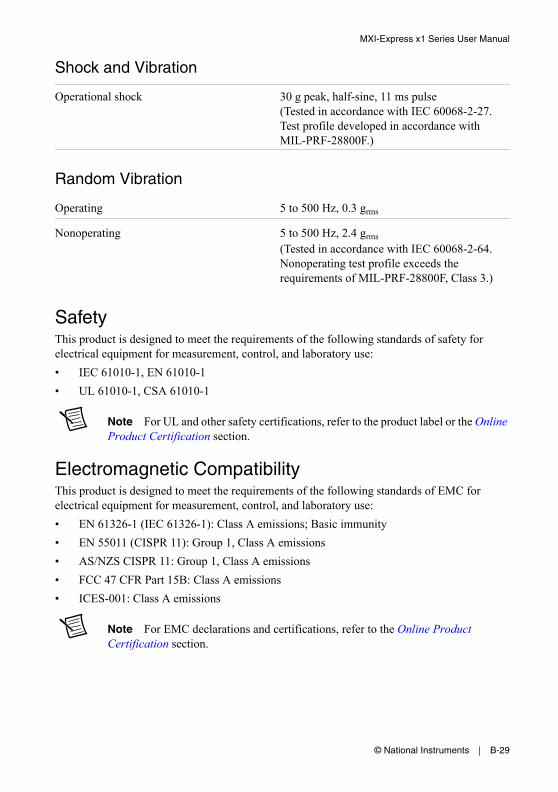
Shock and Vibration
Operational shock 30 g peak, half-sine, 11 ms pulse (Tested in accordance with IEC 60068-2-27. Test profile developed in accordance with MIL-PRF-28800F.)
(Tested in accordance with IEC 60068-2-64. Nonoperating test profile exceeds the requirements of MIL-PRF-28800F, Class 3.)
SafetyThis product is designed to meet the requirements of the following standards of safety for electrical equipment for measurement, control, and laboratory use:
• IEC 61010-1, EN 61010-1
• UL 61010-1, CSA 61010-1
Note For UL and other safety certifications, refer to the product label or the Online Product Certification section.
Electromagnetic CompatibilityThis product is designed to meet the requirements of the following standards of EMC for electrical equipment for measurement, control, and laboratory use:
• EN 61326-1 (IEC 61326-1): Class A emissions; Basic immunity
• EN 55011 (CISPR 11): Group 1, Class A emissions
• AS/NZS CISPR 11: Group 1, Class A emissions
• FCC 47 CFR Part 15B: Class A emissions
• ICES-001: Class A emissions
Note For EMC declarations and certifications, refer to the Online Product Certification section.
CE ComplianceThis product meets the essential requirements of applicable European Directives as follows:
Online Product CertificationTo obtain product certifications and the Declaration of Conformity (DoC) for this product, visit ni.com/certification, search by model number or product line, and click the appropriate link in the Certification column.
B-16 | ni.com
Appendix B Specifications
Environmental ManagementNI is committed to designing and manufacturing products in an environmentally responsible manner. NI recognizes that eliminating certain hazardous substances from our products is beneficial to the environment and to NI customers.
For additional environmental information, refer to the Minimize Our Environmental Impact web page at ni.com/environment. This page contains the environmental regulations and directives with which NI complies, as well as other environmental information not included in this document.
Waste Electrical and Electronic Equipment (WEEE)EU Customers At the end of the product life cycle, all products must be sent to a WEEE recycling center. For more information about WEEE recycling centers, National Instruments WEEE initiatives, and compliance with WEEE Directive 2002/96/EC on Waste and Electronic Equipment, visit ni.com/environment/weee.
CleaningIf you need to clean the module, use a soft, nonmetallic brush. Make sure that the module is completely dry and free from contaminants before returning it to service.
NI PXI-8364 (199991x-02L)
Note These specifications are typical at 25 °C, unless otherwise stated, and are subject to change without notice.
Physical
Dimensions 10.0 cm × 16.0 cm (3.9 in. × 6.3 in.)
Maximum cable length 7 m
Slot requirements One PXI or PXI hybrid peripheral slot
Compatibility Fully compatible with the PXI Hardware Specification, Revision 2.1
Weight 0.13 kg (0.28 lb) typical
RoHSNational Instruments
(RoHS) National Instruments RoHS ni.com/environment/rohs_china (For information about China RoHS compliance, go to ni.com/environment/rohs_china.)
Ambient temperature range 0 to 55 °C(Tested in accordance with IEC 60068-2-1 and IEC 60068-2-2.)
Operating relative humidity 10 to 90%, noncondensing (Tested in accordance with IEC 60068-2-56.)
Storage Environment
Ambient temperature range -40 to 70 °C(Tested in accordance with IEC 60068-2-1 and IEC 60068-2-2.)
Relative humidity range 5 to 95%, noncondensing (Tested in accordance with IEC 60068-2-56.)
Shock and Vibration
Operational shock 30 g peak, half-sine, 11 ms pulse (Tested in accordance with IEC 60068-2-27. Test profile developed in accordance with MIL-PRF-28800F.)
Power Rail Typical Current Maximum Current
+3.3 V 420 mA 650 mA
+5 V 13 mA 15 mA
+12 V 10 mA 12 mA
-12 V 0 A 0 A
VIO 0 A 1 mA
B-18 | ni.com
Appendix B Specifications
Nonoperating shock 50 g peak, half-sine, 11 ms pulse (Tested in accordance with IEC 60068-2-27.)
Random Vibration
Operating 5 to 500 Hz, 0.3 grms
Nonoperating 5 to 500 Hz, 2.4 grms
(Tested in accordance with IEC 60068-2-64. Nonoperating test profile exceeds the requirements of MIL-PRF-28800F, Class 3.)
SafetyThis product is designed to meet the requirements of the following standards of safety for electrical equipment for measurement, control, and laboratory use:
• IEC 61010-1, EN 61010-1
• UL 61010-1, CSA 61010-1
Note For UL and other safety certifications, refer to the product label or the Online Product Certification section.
Electromagnetic CompatibilityThis product is designed to meet the requirements of the following standards of EMC for electrical equipment for measurement, control, and laboratory use:
• EN 61326-1 (IEC 61326-1): Class A emissions; Basic immunity
• EN 55011 (CISPR 11): Group 1, Class A emissions
• AS/NZS CISPR 11: Group 1, Class A emissions
• FCC 47 CFR Part 15B: Class A emissions
• ICES-001: Class A emissions
Note For EMC declarations and certifications, refer to the Online Product Certification section.
CE ComplianceThis product meets the essential requirements of applicable European Directives as follows:
Online Product CertificationTo obtain product certifications and the Declaration of Conformity (DoC) for this product, visit ni.com/certification, search by model number or product line, and click the appropriate link in the Certification column.
Environmental ManagementNI is committed to designing and manufacturing products in an environmentally responsible manner. NI recognizes that eliminating certain hazardous substances from our products is beneficial to the environment and to NI customers.
For additional environmental information, refer to the Minimize Our Environmental Impact web page at ni.com/environment. This page contains the environmental regulations and directives with which NI complies, as well as other environmental information not included in this document.
Waste Electrical and Electronic Equipment (WEEE)EU Customers At the end of the product life cycle, all products must be sent to a WEEE recycling center. For more information about WEEE recycling centers, National Instruments WEEE initiatives, and compliance with WEEE Directive 2002/96/EC on Waste and Electronic Equipment, visit ni.com/environment/weee.
CleaningIf you need to clean the module, use a soft, nonmetallic brush. Make sure that the module is completely dry and free from contaminants before returning it to service.
RoHSNational Instruments
(RoHS) National Instruments RoHS ni.com/environment/rohs_china (For information about China RoHS compliance, go to ni.com/environment/rohs_china.)
B-20 | ni.com
Appendix B Specifications
NI PXI-8367 (199991x-04L)
Note These specifications are typical at 25 °C, unless otherwise stated, and are subject to change without notice.
Connectivity Support for Daisy-Chaining
Slot Type Compatibility
Physical
Dimensions 10.0 cm × 16.0 cm (3.9 in. × 6.3 in.)
Maximum cable length 200 m (Fiber-Optic)
Slot requirements One PXI or PXI hybrid peripheral slot
Compatibility Fully compatible with the PXI Hardware Specification, Revision 2.1
Weight 0.14 kg (0.31 lb) typical
From Chassis Targets
Slot Type Product
PXI Chassis
NI PXI-8366 NI PXI-8336*
PXI or PXIe Hybrid NI PXI-8367 —
PXI NI PXI-8336* — *
* The NI PXI-8336 is part of the MXI-4 family of products and has the same cable connector as the NI PCI-8366, NI PXI-8366, and NI PXI-8367, but will only function when connected in valid cases as shown.
Ambient temperature range 0 to 55 °C(Tested in accordance with IEC 60068-2-1 and IEC 60068-2-2.)
Operating relative humidity 10 to 90%, noncondensing (Tested in accordance with IEC 60068-2-56.)
LED Color Meaning
PWR/LINK Off Power is off
Blinking Red Power is out of spec
Solid Amber Power is within spec; no link to chassis
Solid Green Power is within spec; link established
Power Rail Typical Current Maximum Current
+3.3 V 525 mA 800 mA
+5 V 8 mA 10 mA
+12 V 10 mA 12 mA
-12 V 0 A 0 A
VIO 0 A 1 mA
B-22 | ni.com
Appendix B Specifications
Storage Environment
Ambient temperature range -40 to 70 °C (Tested in accordance with IEC 60068-2-1 and IEC 60068-2-2.)
Storage relative humidity 5 to 95%, noncondensing (Tested in accordance with IEC 60068-2-56.)
Shock and Vibration
Operational shock 30 g peak, half-sine, 11 ms pulse (Tested in accordance with IEC 60068-2-27. Test profile developed in accordance with MIL-PRF-28800F.)
Nonoperating shock 50 g peak, half-sine, 11 ms pulse (Tested in accordance with IEC 60068-2-27.)
Random Vibration
Operating 5 to 500 Hz, 0.3 grms
Nonoperating 5 to 500 Hz, 2.4 grms
(Tested in accordance with IEC 60068-2-64. Nonoperating test profile exceeds the requirements of MIL-PRF-28800F, Class 3.)
SafetyThis product is designed to meet the requirements of the following standards of safety for electrical equipment for measurement, control, and laboratory use:
• IEC 61010-1, EN 61010-1
• UL 61010-1, CSA 61010-1
Note For UL and other safety certifications, refer to the product label or the Online Product Certification section.
Electromagnetic CompatibilityThis product is designed to meet the requirements of the following standards of EMC for electrical equipment for measurement, control, and laboratory use:
• EN 61326-1 (IEC 61326-1): Class A emissions; Basic immunity
Online Product CertificationTo obtain product certifications and the Declaration of Conformity (DoC) for this product, visit ni.com/certification, search by model number or product line, and click the appropriate link in the Certification column.
Environmental ManagementNI is committed to designing and manufacturing products in an environmentally responsible manner. NI recognizes that eliminating certain hazardous substances from our products is beneficial to the environment and to NI customers.
For additional environmental information, refer to the Minimize Our Environmental Impact web page at ni.com/environment. This page contains the environmental regulations and directives with which NI complies, as well as other environmental information not included in this document.
Waste Electrical and Electronic Equipment (WEEE)EU Customers At the end of the product life cycle, all products must be sent to a WEEE recycling center. For more information about WEEE recycling centers, National Instruments WEEE initiatives, and compliance with WEEE Directive 2002/96/EC on Waste and Electronic Equipment, visit ni.com/environment/weee.
RoHSNational Instruments
(RoHS) National Instruments RoHS ni.com/environment/rohs_china (For information about China RoHS compliance, go to ni.com/environment/rohs_china.)
B-24 | ni.com
Appendix B Specifications
CleaningIf you need to clean the module, use a soft, nonmetallic brush. Make sure that the module is completely dry and free from contaminants before returning it to service.
NI PXI-8368 (157298x-02L)
Note These specifications are typical at 25 °C, unless otherwise stated, and are subject to change without notice.
Physical
Dimensions 10.0 cm × 16.0 cm (3.9 in. × 6.3 in.)
Maximum cable length 200 m
Slot requirements One PXI controller slot
Compatibility Fully compatible with the PXI Hardware Specification, Revision 1.0
Ambient temperature range 0 to 55 °C(Tested in accordance with IEC 60068-2-1 and IEC 60068-2-2.)
Operating relative humidity 10 to 90%, noncondensing (Tested in accordance with IEC 60068-2-56.)
Storage Environment
Ambient temperature range -40 to 70 °C(Tested in accordance with IEC 60068-2-1 and IEC 60068-2-2.)
Relative humidity range 5 to 95%, noncondensing (Tested in accordance with IEC 60068-2-56.)
Shock and Vibration
Operational shock 30 g peak, half-sine, 11 ms pulse (Tested in accordance with IEC 60068-2-27. Test profile developed in accordance with MIL-PRF-28800F.)
Nonoperating shock 50 g peak, half-sine, 11 ms pulse (Tested in accordance with IEC 60068-2-27.)
Random Vibration
Operating 5 to 500 Hz, 0.3 grms
Nonoperating 5 to 500 Hz, 2.4 grms
(Tested in accordance with IEC 60068-2-64. Nonoperating test profile exceeds the requirements of MIL-PRF-28800F, Class 3.)
B-26 | ni.com
Appendix B Specifications
SafetyThis product is designed to meet the requirements of the following standards of safety for electrical equipment for measurement, control, and laboratory use:
• IEC 61010-1, EN 61010-1
• UL 61010-1, CSA 61010-1
Note For UL and other safety certifications, refer to the product label or the Online Product Certification section.
Electromagnetic CompatibilityThis product is designed to meet the requirements of the following standards of EMC for electrical equipment for measurement, control, and laboratory use:
• EN 61326-1 (IEC 61326-1): Class A emissions; Basic immunity
• EN 55011 (CISPR 11): Group 1, Class A emissions
• AS/NZS CISPR 11: Group 1, Class A emissions
• FCC 47 CFR Part 15B: Class A emissions
• ICES-001: Class A emissions
Note For EMC declarations and certifications, refer to the Online Product Certification section.
CE ComplianceThis product meets the essential requirements of applicable European Directives as follows:
Online Product CertificationTo obtain product certifications and the Declaration of Conformity (DoC) for this product, visit ni.com/certification, search by model number or product line, and click the appropriate link in the Certification column.
Environmental ManagementNI is committed to designing and manufacturing products in an environmentally responsible manner. NI recognizes that eliminating certain hazardous substances from our products is beneficial to the environment and to NI customers.
For additional environmental information, refer to the Minimize Our Environmental Impact web page at ni.com/environment. This page contains the environmental regulations and
directives with which NI complies, as well as other environmental information not included in this document.
Waste Electrical and Electronic Equipment (WEEE)EU Customers At the end of the product life cycle, all products must be sent to a WEEE recycling center. For more information about WEEE recycling centers, National Instruments WEEE initiatives, and compliance with WEEE Directive 2002/96/EC on Waste and Electronic Equipment, visit ni.com/environment/weee.
CleaningIf you need to clean the module, use a soft, nonmetallic brush. Make sure that the module is completely dry and free from contaminants before returning it to service.
NI PXIe-8360 (194402x-01L)
Note These specifications are typical at 25 °C, unless otherwise stated, and are subject to change without notice.
Physical
Dimensions 10.0 cm × 16.0 cm (3.9 in. × 6.3 in.)
Maximum cable length 7 m
Slot requirements One PXI Express system slot
Compatibility Fully compatible with the PXI-5 Express Hardware Specification, Revision 1.0
Weight 0.17 kg (0.37 lb) typical
RoHSNational Instruments
(RoHS) National Instruments RoHS ni.com/environment/rohs_china (For information about China RoHS compliance, go to ni.com/environment/rohs_china.)
B-28 | ni.com
Appendix B Specifications
Power Requirements
Environment
Maximum altitude 2,000 m
Pollution Degree 2
Indoor use only.
Operating Environment
Ambient temperature range 0 to 55 °C (Tested in accordance with IEC 60068-2-1 and IEC 60068-2-2. Meets MIL-PRF-28800F Class 3 low temperature limit and MIL-PRF-28800F Class 2 high temperature limit.)
Operating relative humidity 10 to 90%, noncondensing (Tested in accordance with IEC 60068-2-56.)
Storage Environment
Ambient temperature range -40 to 71 °C (Tested in accordance with IEC 60068-2-1 and IEC 60068-2-2. Meets MIL-PRF-28800F Class 3 limits.)
Relative humidity range 5 to 95%, noncondensing (Tested in accordance with IEC 60068-2-56)
Operational shock 30 g peak, half-sine, 11 ms pulse (Tested in accordance with IEC 60068-2-27. Test profile developed in accordance with MIL-PRF-28800F.)
Random Vibration
Operating 5 to 500 Hz, 0.3 grms
Nonoperating 5 to 500 Hz, 2.4 grms
(Tested in accordance with IEC 60068-2-64. Nonoperating test profile exceeds the requirements of MIL-PRF-28800F, Class 3.)
SafetyThis product is designed to meet the requirements of the following standards of safety for electrical equipment for measurement, control, and laboratory use:
• IEC 61010-1, EN 61010-1
• UL 61010-1, CSA 61010-1
Note For UL and other safety certifications, refer to the product label or the Online Product Certification section.
Electromagnetic CompatibilityThis product is designed to meet the requirements of the following standards of EMC for electrical equipment for measurement, control, and laboratory use:
• EN 61326-1 (IEC 61326-1): Class A emissions; Basic immunity
• EN 55011 (CISPR 11): Group 1, Class A emissions
• AS/NZS CISPR 11: Group 1, Class A emissions
• FCC 47 CFR Part 15B: Class A emissions
• ICES-001: Class A emissions
Note For EMC declarations and certifications, refer to the Online Product Certification section.
B-30 | ni.com
Appendix B Specifications
CE ComplianceThis product meets the essential requirements of applicable European Directives as follows:
Online Product CertificationTo obtain product certifications and the Declaration of Conformity (DoC) for this product, visit ni.com/certification, search by model number or product line, and click the appropriate link in the Certification column.
Environmental ManagementNI is committed to designing and manufacturing products in an environmentally responsible manner. NI recognizes that eliminating certain hazardous substances from our products is beneficial to the environment and to NI customers.
For additional environmental information, refer to the Minimize Our Environmental Impact web page at ni.com/environment. This page contains the environmental regulations and directives with which NI complies, as well as other environmental information not included in this document.
Waste Electrical and Electronic Equipment (WEEE)EU Customers At the end of the product life cycle, all products must be sent to a WEEE recycling center. For more information about WEEE recycling centers, National Instruments WEEE initiatives, and compliance with WEEE Directive 2002/96/EC on Waste and Electronic Equipment, visit ni.com/environment/weee.
CleaningIf you need to clean the module, use a soft, nonmetallic brush. Make sure that the module is completely dry and free from contaminants before returning it to service.
RoHSNational Instruments
(RoHS) National Instruments RoHS ni.com/environment/rohs_china (For information about China RoHS compliance, go to ni.com/environment/rohs_china.)
Note These specifications are typical at 25 °C, unless otherwise stated, and are subject to change without notice.
Physical
Dimensions 10.0 cm × 16.0 cm (3.9 in. × 6.3 in.)
Maximum cable length 7 m
Slot requirements One peripheral slot (PXI Express or CompactPCI Express)
Compatibility Fully compatible with the PXI Express Hardware Specification, Revision 1.0 and the PICMG CompactPCI Express EXP.0 R1.0 Specification
Weight 0.15 kg (0.33 lb) typical
Power Requirements
Environment
Maximum altitude 2,000 m
Pollution Degree 2
Indoor use only.
Power Rail Typical Current Maximum Current
+3.3 V 480 mA 700 mA
+12 V 430 mA 750 mA
+5 VAux 5 mA 20 mA
B-32 | ni.com
Appendix B Specifications
Operating Environment
Ambient temperature range 0 to 55 °C (Tested in accordance with IEC 60068-2-1 and IEC 60068-2-2. Meets MIL-PRF-28800F Class 3 low temperature limit and MIL-PRF-28800F Class 2 high temperature limit.)
Operating relative humidity 10 to 90%, noncondensing (Tested in accordance with IEC 60068-2-56.)
Storage Environment
Ambient temperature range -40 to 71 °C (Tested in accordance with IEC 60068-2-1 and IEC 60068-2-2. Meets MIL-PRF-28800F Class 3 limits.)
Relative humidity range 5 to 95%, noncondensing (Tested in accordance with IEC 60068-2-56)
Shock and Vibration
Operational shock 30 g peak, half-sine, 11 ms pulse (Tested in accordance with IEC 60068-2-27. Meets MIL-PRF-28800F Class 2 limits.)
Random Vibration
Operating 5 to 500 Hz, 0.3 grms
Nonoperating 5 to 500 Hz, 2.4 grms
(Tested in accordance with IEC 60068-2-64. Nonoperating test profile exceeds the requirements of MIL-PRF-28800F, Class 3.)
Caution Clean the NI PXIe-8364 with a soft nonmetallic brush. Make sure that the device is completely dry and free from contaminants before returning it to service.
Note For full EMC compliance, operate this device with shielded cabling. In addition, all covers and filler panels must be installed. To obtain the DoC for this product, visit ni.com/certification, search by model number or product line, and click the appropriate link in the Certification column.
SafetyThis product is designed to meet the requirements of the following standards of safety for electrical equipment for measurement, control, and laboratory use:
• IEC 61010-1, EN 61010-1
• UL 61010-1, CSA 61010-1
Note For UL and other safety certifications, refer to the product label or the Online Product Certification section.
Electromagnetic CompatibilityThis product is designed to meet the requirements of the following standards of EMC for electrical equipment for measurement, control, and laboratory use:
• EN 61326-1 (IEC 61326-1): Class A emissions; Basic immunity
• EN 55011 (CISPR 11): Group 1, Class A emissions
• AS/NZS CISPR 11: Group 1, Class A emissions
• FCC 47 CFR Part 15B: Class A emissions
• ICES-001: Class A emissions
CE ComplianceThis product meets the essential requirements of applicable European Directives, as amended for CE marking, as follows:
Online Product CertificationTo obtain product certifications and the Declaration of Conformity (DoC) for this product, visit ni.com/certification, search by model number or product line, and click the appropriate link in the Certification column.
Environmental ManagementNI is committed to designing and manufacturing products in an environmentally responsible manner. NI recognizes that eliminating certain hazardous substances from our products is beneficial to the environment and to NI customers.
For additional environmental information, refer to the Minimize Our Environmental Impact web page at ni.com/environment. This page contains the environmental regulations and directives with which NI complies, as well as other environmental information not included in this document.
B-34 | ni.com
Appendix B Specifications
Waste Electrical and Electronic Equipment (WEEE)EU Customers At the end of the product life cycle, all products must be sent to a WEEE recycling center. For more information about WEEE recycling centers, National Instruments WEEE initiatives, and compliance with WEEE Directive 2002/96/EC on Waste and Electronic Equipment, visit ni.com/environment/weee.
CleaningIf you need to clean the module, use a soft, nonmetallic brush. Make sure that the module is completely dry and free from contaminants before returning it to service.
NI ExpressCard-8360 (198266x-01L)
Note These specifications are typical at 25 °C, unless otherwise stated, and are subject to change without notice.
Physical
Dimensions 10.2 cm × 3.4 cm (4.0 in. × 1.3 in.)
Maximum cable length 7 m
Slot requirements One 34 mm or 54 mm slot (ExpressCard)
Ambient temperature range 0 to 65 °C(Tested in accordance with IEC 60068-2-1 and IEC 60068-2-2.)
Operating relative humidity 5 to 95%, noncondensing (Tested in accordance with IEC 60068-2-56.)
Storage Environment
Ambient temperature range -20 to 65 °C (Tested in accordance with IEC 60068-2-1 and IEC 60068-2-2.)
Nonoperating thermal shock -20 to 65 °C, 5 shocks
Shock and Vibration
Nonoperating shock 50 g, 11 ms(Tested in accordance with IEC 60068-2-27.) Test profile developed in accordance with MIL-PRF-28800F.
Nonoperating vibration sinusoidal 15 g 100 to 2000 Hz (Tested in accordance with IEC 60068-2-6.) Nonoperating test profile exceeds the requirements of MIL-PRF-28800F, Class 3.)
Nonoperating drop test 2 drops in 3 mutually exclusive axes from 75 cm onto no-cushioning vinyl tile surface
B-36 | ni.com
Appendix B Specifications
SafetyThis product is designed to meet the requirements of the following standards of safety for electrical equipment for measurement, control, and laboratory use:
• IEC 61010-1, EN 61010-1
• UL 61010-1, CSA 61010-1
Note For UL and other safety certifications, refer to the product label or the Online Product Certification section.
Electromagnetic CompatibilityThis product is designed to meet the requirements of the following standards of EMC for electrical equipment for measurement, control, and laboratory use:
• EN 61326-1 (IEC 61326-1): Class A emissions; Basic immunity
• EN 55011 (CISPR 11): Group 1, Class A emissions
• AS/NZS CISPR 11: Group 1, Class A emissions
• FCC 47 CFR Part 15B: Class A emissions
• ICES-001: Class A emissions
Note For EMC declarations and certifications, refer to the Online Product Certification section.
CE ComplianceThis product meets the essential requirements of applicable European Directives as follows:
Online Product CertificationTo obtain product certifications and the Declaration of Conformity (DoC) for this product, visit ni.com/certification, search by model number or product line, and click the appropriate link in the Certification column.
Environmental ManagementNI is committed to designing and manufacturing products in an environmentally responsible manner. NI recognizes that eliminating certain hazardous substances from our products is beneficial to the environment and to NI customers.
For additional environmental information, refer to the Minimize Our Environmental Impact web page at ni.com/environment. This page contains the environmental regulations and
directives with which NI complies, as well as other environmental information not included in this document.
Waste Electrical and Electronic Equipment (WEEE)EU Customers At the end of the product life cycle, all products must be sent to a WEEE recycling center. For more information about WEEE recycling centers, National Instruments WEEE initiatives, and compliance with WEEE Directive 2002/96/EC on Waste and Electronic Equipment, visit ni.com/environment/weee.
CleaningIf you need to clean the module, use a soft, nonmetallic brush. Make sure that the module is completely dry and free from contaminants before returning it to service.
RoHSNational Instruments
(RoHS) National Instruments RoHS ni.com/environment/rohs_china (For information about China RoHS compliance, go to ni.com/environment/rohs_china.)
This appendix lists the system specifications for the following products only:
• NI PCIe-8361 (195315x-01L)
• NI PCIe-8361 (191376x-02) 1
• NI PCIe-8362 (191376x-01) 1
• NI PXI-8361 (199991x-01L) 1
• NI PXI-8366 (199991x-03L) 1
• NI ExpressCard-8360 (192290x-01) 1
Note The model numbers listed below are followed by their specific NI assembly numbers in parentheses. x denotes all letter revisions of the assembly. Ensure the specifications of interest match the NI assembly number that is printed on either the front or back side of the board.
For specifications on current generation products, refer to Appendix B, Specifications.
NI PCIe-8361 (195315x-01L)
Note These specifications are typical at 25 °C, unless otherwise stated, and are subject to change without notice.
1 No longer available for purchase.
C-2 | ni.com
Appendix C Specifications for Legacy Products
Functional Block DiagramFigure C-1. NI PCIe-8361 Repeater Version (195315x-01L) Block Diagram
Physical
Dimensions 6.9 cm × 8.9 cm (2.7 in. × 3.5 in.)
Maximum cable length 7 m
Slot requirements One slot (PCI Express, standard height or low profile)
Compatibility Fully compatible with the PCI Express Specification, Revision 1.0a
Ambient temperature range 0 to 55 °C(Tested in accordance with IEC 60068-2-1 and IEC-60068-2-2.)
Relative humidity range 10 to 90%, noncondensing (Tested in accordance with IEC 60068-2-56.)
Storage Environment
Ambient temperature range -20 to 70 °C(Tested in accordance with IEC 60068-2-1 and IEC 60068-2-2.)
Relative humidity range 5 to 95%, noncondensing (Tested in accordance with IEC 60068-2-56.)
SafetyThis product is designed to meet the requirements of the following standards of safety for electrical equipment for measurement, control, and laboratory use:
• IEC 61010-1, EN 61010-1
• UL 61010-1, CSA 61010-1
Note For UL and other safety certifications, refer to the product label or the Online Product Certification section.
Electromagnetic CompatibilityThis product is designed to meet the requirements of the following standards of EMC for electrical equipment for measurement, control, and laboratory use:
• EN 61326-1 (IEC 61326-1): Class A emissions; Basic immunity
• EN 55011 (CISPR 11): Group 1, Class A emissions
• AS/NZS CISPR 11: Group 1, Class A emissions
• FCC 47 CFR Part 15B: Class A emissions
C-4 | ni.com
Appendix C Specifications for Legacy Products
• ICES-001: Class A emissions
Note For EMC declarations and certifications, refer to the Online Product Certification section.
CE ComplianceThis product meets the essential requirements of applicable European Directives as follows:
Online Product CertificationTo obtain product certifications and the Declaration of Conformity (DoC) for this product, visit ni.com/certification, search by model number or product line, and click the appropriate link in the Certification column.
Environmental ManagementNI is committed to designing and manufacturing products in an environmentally responsible manner. NI recognizes that eliminating certain hazardous substances from our products is beneficial to the environment and to NI customers.
For additional environmental information, refer to the Minimize Our Environmental Impact web page at ni.com/environment. This page contains the environmental regulations and directives with which NI complies, as well as other environmental information not included in this document.
Waste Electrical and Electronic Equipment (WEEE)EU Customers At the end of the product life cycle, all products must be sent to a WEEE recycling center. For more information about WEEE recycling centers, National Instruments WEEE initiatives, and compliance with WEEE Directive 2002/96/EC on Waste and Electronic Equipment, visit ni.com/environment/weee.
CleaningIf you need to clean the module, use a soft, nonmetallic brush. Make sure that the module is completely dry and free from contaminants before returning it to service.
RoHSNational Instruments
(RoHS) National Instruments RoHS ni.com/environment/rohs_china (For information about China RoHS compliance, go to ni.com/environment/rohs_china.)
Note These specifications are typical at 25 °C, unless otherwise stated, and are subject to change without notice.
Physical
Dimensions 10.7 cm × 17.5 cm (4.4 in. × 6.9 in.)
Maximum cable length 7 m
Slot requirements One slot (PCI Express, standard height)
Compatibility Fully compatible with the PCI Express Specification, Revision 1.0a
Weight 0.13 kg (0.30 lb) typical
Power Requirements
Environment
Maximum altitude 2,000 m
Pollution Degree 2
Indoor use only
Operating Environment
Ambient temperature range 0 to 55 °C(Tested in accordance with IEC 60068-2-1 and IEC 60068-2-2.)
Relative humidity range 10 to 90%, noncondensing (Tested in accordance with IEC 60068-2-56.)
Power Rail Typical Current Maximum Current
+3.3 V 1.8 A 2.0 A
+3.3 VAux 0 A 0 A
+12 V 0 A 0 A
C-6 | ni.com
Appendix C Specifications for Legacy Products
Storage Environment
Ambient temperature range -40 to 70 °C(Tested in accordance with IEC 60068-2-1 and IEC 60068-2-2.)
Relative humidity range 5 to 95%, noncondensing (Tested in accordance with IEC-60068-2-56.)
SafetyThis product is designed to meet the requirements of the following standards of safety for electrical equipment for measurement, control, and laboratory use:
• IEC 61010-1, EN 61010-1
• UL 61010-1, CSA 61010-1
Note For UL and other safety certifications, refer to the product label or the Online Product Certification section.
Electromagnetic CompatibilityThis product is designed to meet the requirements of the following standards of EMC for electrical equipment for measurement, control, and laboratory use:
• EN 61326-1 (IEC 61326-1): Class A emissions; Basic immunity
• EN 55011 (CISPR 11): Group 1, Class A emissions
• AS/NZS CISPR 11: Group 1, Class A emissions
• FCC 47 CFR Part 15B: Class A emissions
• ICES-001: Class A emissions
Note For EMC declarations and certifications, refer to the Online Product Certification section.
CE ComplianceThis product meets the essential requirements of applicable European Directives as follows:
Online Product CertificationTo obtain product certifications and the Declaration of Conformity (DoC) for this product, visit ni.com/certification, search by model number or product line, and click the appropriate link in the Certification column.
Environmental ManagementNI is committed to designing and manufacturing products in an environmentally responsible manner. NI recognizes that eliminating certain hazardous substances from our products is beneficial to the environment and to NI customers.
For additional environmental information, refer to the Minimize Our Environmental Impact web page at ni.com/environment. This page contains the environmental regulations and directives with which NI complies, as well as other environmental information not included in this document.
Waste Electrical and Electronic Equipment (WEEE)EU Customers At the end of the product life cycle, all products must be sent to a WEEE recycling center. For more information about WEEE recycling centers, National Instruments WEEE initiatives, and compliance with WEEE Directive 2002/96/EC on Waste and Electronic Equipment, visit ni.com/environment/weee.
CleaningIf you need to clean the module, use a soft, nonmetallic brush. Make sure that the module is completely dry and free from contaminants before returning it to service.
NI PCIe-8362 (191376x-01)
Note These specifications are typical at 25 °C, unless otherwise stated, and are subject to change without notice.
Physical
Dimensions 10.7 cm × 17.5 cm (4.4 in. × 6.9 in.)
Maximum cable length 7 m
Slot requirements One slot (PCI Express, standard height)
Compatibility Fully compatible with the PCI Express Specification, Revision 1.0a
Weight 0.13 kg (0.30 lb) typical
RoHSNational Instruments
(RoHS) National Instruments RoHS ni.com/environment/rohs_china (For information about China RoHS compliance, go to ni.com/environment/rohs_china.)
C-8 | ni.com
Appendix C Specifications for Legacy Products
Power Requirements
Environment
Maximum altitude 2,000 m
Pollution Degree 2
Indoor use only
Operating Environment
Ambient temperature range 0 to 55 °C (Tested in accordance with IEC 60068-2-1 and IEC 60068-2-2.)
Relative humidity range 10 to 90%, noncondensing (Tested in accordance with IEC 60068-2-56.)
Storage Environment
Ambient temperature range -40 to 70 °C(Tested in accordance with IEC 60068-2-1 and IEC 60068-2-2.)
Relative humidity range 5 to 95%, noncondensing (Tested in accordance with IEC 60068-2-56.)
SafetyThis product is designed to meet the requirements of the following standards of safety for electrical equipment for measurement, control, and laboratory use:
• IEC 61010-1, EN 61010-1
• UL 61010-1, CSA 61010-1
Note For UL and other safety certifications, refer to the product label or the Online Product Certification section.
Electromagnetic CompatibilityThis product is designed to meet the requirements of the following standards of EMC for electrical equipment for measurement, control, and laboratory use:
• EN 61326-1 (IEC 61326-1): Class A emissions; Basic immunity
• EN 55011 (CISPR 11): Group 1, Class A emissions
• AS/NZS CISPR 11: Group 1, Class A emissions
• FCC 47 CFR Part 15B: Class A emissions
• ICES-001: Class A emissions
Note For EMC declarations and certifications, refer to the Online Product Certification section.
CE ComplianceThis product meets the essential requirements of applicable European Directives as follows:
Online Product CertificationTo obtain product certifications and the Declaration of Conformity (DoC) for this product, visit ni.com/certification, search by model number or product line, and click the appropriate link in the Certification column.
Environmental ManagementNI is committed to designing and manufacturing products in an environmentally responsible manner. NI recognizes that eliminating certain hazardous substances from our products is beneficial to the environment and to NI customers.
For additional environmental information, refer to the Minimize Our Environmental Impact web page at ni.com/environment. This page contains the environmental regulations and directives with which NI complies, as well as other environmental information not included in this document.
C-10 | ni.com
Appendix C Specifications for Legacy Products
Waste Electrical and Electronic Equipment (WEEE)EU Customers At the end of the product life cycle, all products must be sent to a WEEE recycling center. For more information about WEEE recycling centers, National Instruments WEEE initiatives, and compliance with WEEE Directive 2002/96/EC on Waste and Electronic Equipment, visit ni.com/environment/weee.
CleaningIf you need to clean the module, use a soft, nonmetallic brush. Make sure that the module is completely dry and free from contaminants before returning it to service.
NI PXI-8361 (199991x-01L)
Note These specifications are typical at 25 °C, unless otherwise stated, and are subject to change without notice.
Functional Block DiagramFigure C-2. NI PXI-8361 (199991x-01L) Block Diagram
RoHSNational Instruments
(RoHS) National Instruments RoHS ni.com/environment/rohs_china (For information about China RoHS compliance, go to ni.com/environment/rohs_china.)
Solid Amber Power is within spec; no link to chassis
Solid Green Power is within spec; link established
H
C-12 | ni.com
Appendix C Specifications for Legacy Products
Power Requirements
Environment
Maximum altitude 2,000 m
Pollution Degree 2
Indoor use only.
Operating Environment
Ambient temperature range 0 to 55 °C(Tested in accordance with IEC 60068-2-1 and IEC 60068-2-2.)
Operating relative humidity 10 to 90%, noncondensing (Tested in accordance with IEC 60068-2-56.)
Storage Environment
Ambient temperature range -40 to 70 °C (Tested in accordance with IEC 60068-2-1 and IEC 60068-2-2.)
Storage relative humidity 5 to 95%, noncondensing (Tested in accordance with IEC 60068-2-56.)
Shock and Vibration
Operational shock 30 g peak, half-sine, 11 ms pulse (Tested in accordance with IEC 60068-2-27. Test profile developed in accordance with MIL-PRF-28800F.)
Nonoperating shock 50 g peak, half-sine, 11 ms pulse (Tested in accordance with IEC 60068-2-27.)
Random Vibration
Operating 5 to 500 Hz, 0.3 grms
Nonoperating 5 to 500 Hz, 2.4 grms
(Tested in accordance with IEC 60068-2-64. Nonoperating test profile exceeds the requirements of MIL-PRF-28800F, Class 3.)
SafetyThis product is designed to meet the requirements of the following standards of safety for electrical equipment for measurement, control, and laboratory use:
• IEC 61010-1, EN 61010-1
• UL 61010-1, CSA 61010-1
Note For UL and other safety certifications, refer to the product label or the Online Product Certification section.
Electromagnetic CompatibilityThis product is designed to meet the requirements of the following standards of EMC for electrical equipment for measurement, control, and laboratory use:
• EN 61326-1 (IEC 61326-1): Class A emissions; Basic immunity
• EN 55011 (CISPR 11): Group 1, Class A emissions
• AS/NZS CISPR 11: Group 1, Class A emissions
• FCC 47 CFR Part 15B: Class A emissions
• ICES-001: Class A emissions
Note For EMC declarations and certifications, refer to the Online Product Certification section.
CE ComplianceThis product meets the essential requirements of applicable European Directives as follows:
Online Product CertificationTo obtain product certifications and the Declaration of Conformity (DoC) for this product, visit ni.com/certification, search by model number or product line, and click the appropriate link in the Certification column.
Environmental ManagementNI is committed to designing and manufacturing products in an environmentally responsible manner. NI recognizes that eliminating certain hazardous substances from our products is beneficial to the environment and to NI customers.
For additional environmental information, refer to the Minimize Our Environmental Impact web page at ni.com/environment. This page contains the environmental regulations and directives with which NI complies, as well as other environmental information not included in this document.
Waste Electrical and Electronic Equipment (WEEE)EU Customers At the end of the product life cycle, all products must be sent to a WEEE recycling center. For more information about WEEE recycling centers, National Instruments WEEE initiatives, and compliance with WEEE Directive 2002/96/EC on Waste and Electronic Equipment, visit ni.com/environment/weee.
CleaningIf you need to clean the module, use a soft, nonmetallic brush. Make sure that the module is completely dry and free from contaminants before returning it to service.
RoHSNational Instruments
(RoHS) National Instruments RoHS ni.com/environment/rohs_china (For information about China RoHS compliance, go to ni.com/environment/rohs_china.)
Note These specifications are typical at 25 °C, unless otherwise stated, and are subject to change without notice.
Functional Block DiagramFigure C-3. NI PXI-8366 (199991x-03L) Block Diagram
Connectivity Support From a Host PC
From Host Targets
Slot Type Product
PXI Chassis
NI PXI-8366 NI PXI-8336*
PCI NI PCI-8366 —
PCI NI PCI-8336* — *
* The NI PCI-8336 and PXI-8336 are part of the MXI-4 family of products and have the same cable connectors as the NI PCI-8366, NI PXI-8366, and NI PXI-8367, but will only function when connected in the valid case as shown.
PCIe-to-PCI Bridge
PCI
MXI-Express x1Fiber Optic
PCIe Gen 1 x1
C-16 | ni.com
Appendix C Specifications for Legacy Products
Connectivity Support For Daisy-Chaining
Slot Type Compatibility
LED Status Description
Physical
Dimensions 10.0 cm × 16.0 cm (3.9 in. × 6.3 in.)
Maximum cable length 200 m (Fiber-Optic)
Slot requirements One PXI controller slot
From Chassis Targets
Slot Type Product
PXI Chassis
NI PXI-8366 NI PXI-8336*
PXI or PXIe Hybrid NI PXI-8367 —
PXI NI PXI-8336* — *
* The NI PXI-8336 is part of the MXI-4 family of products and has the same cable connector as the NI PCI-8366, NI PXI-8366, and NI PXI-8367, but will only function when connected in valid cases as shown.
Compatibility Fully compatible with the PXI Hardware Specification, Revision 2.1
Weight 0.15 kg (0.34 lb) typical
Power Requirements
Environment
Maximum altitude 2,000 m
Pollution Degree 2
Indoor use only.
Operating Environment
Ambient temperature range 0 to 55 °C(Tested in accordance with IEC 60068-2-1 and IEC 60068-2-2.)
Operating relative humidity 10 to 90%, noncondensing (Tested in accordance with IEC 60068-2-56.)
Storage Environment
Ambient temperature range -40 to 70 °C(Tested in accordance with IEC 60068-2-1 and IEC 60068-2-2.)
Relative humidity range 5 to 95%, noncondensing (Tested in accordance with IEC 60068-2-56.)
Power Rail Typical Current Maximum Current
+3.3 V 555 mA 850 mA
+5 V 8 mA 10 mA
+12 V 10 mA 12 mA
-12 V 0 A 0 A
VIO 0 A 1 mA
C-18 | ni.com
Appendix C Specifications for Legacy Products
Shock and Vibration
Operational shock 30 g peak, half-sine, 11 ms pulse (Tested in accordance with IEC 60068-2-27. Test profile developed in accordance with MIL-PRF-28800F.)
Nonoperating shock 50 g peak, half-sine, 11 ms pulse (Tested in accordance with IEC 60068-2-27.)
Random Vibration
Operating 5 to 500 Hz, 0.3 grms
Nonoperating 5 to 500 Hz, 2.4 grms
(Tested in accordance with IEC 60068-2-64. Nonoperating test profile exceeds the requirements of MIL-PRF-28800F, Class 3.)
SafetyThis product is designed to meet the requirements of the following standards of safety for electrical equipment for measurement, control, and laboratory use:
• IEC 61010-1, EN 61010-1
• UL 61010-1, CSA 61010-1
Note For UL and other safety certifications, refer to the product label or the Online Product Certification section.
Electromagnetic CompatibilityThis product is designed to meet the requirements of the following standards of EMC for electrical equipment for measurement, control, and laboratory use:
• EN 61326-1 (IEC 61326-1): Class A emissions; Basic immunity
• EN 55011 (CISPR 11): Group 1, Class A emissions
• AS/NZS CISPR 11: Group 1, Class A emissions
• FCC 47 CFR Part 15B: Class A emissions
• ICES-001: Class A emissions
Note For EMC declarations and certifications, refer to the Online Product Certification section.
Online Product CertificationTo obtain product certifications and the Declaration of Conformity (DoC) for this product, visit ni.com/certification, search by model number or product line, and click the appropriate link in the Certification column.
Environmental ManagementNI is committed to designing and manufacturing products in an environmentally responsible manner. NI recognizes that eliminating certain hazardous substances from our products is beneficial to the environment and to NI customers.
For additional environmental information, refer to the Minimize Our Environmental Impact web page at ni.com/environment. This page contains the environmental regulations and directives with which NI complies, as well as other environmental information not included in this document.
Waste Electrical and Electronic Equipment (WEEE)EU Customers At the end of the product life cycle, all products must be sent to a WEEE recycling center. For more information about WEEE recycling centers, National Instruments WEEE initiatives, and compliance with WEEE Directive 2002/96/EC on Waste and Electronic Equipment, visit ni.com/environment/weee.
CleaningIf you need to clean the module, use a soft, nonmetallic brush. Make sure that the module is completely dry and free from contaminants before returning it to service.
RoHSNational Instruments
(RoHS) National Instruments RoHS ni.com/environment/rohs_china (For information about China RoHS compliance, go to ni.com/environment/rohs_china.)
C-20 | ni.com
Appendix C Specifications for Legacy Products
NI ExpressCard-8360 (192290x-01)
Note These specifications are typical at 25 °C, unless otherwise stated, and are subject to change without notice.
Physical
Dimensions 10.2 cm × 3.4 cm (4.0 in. × 1.3 in.)
Maximum cable length 7 m
Slot requirements One 34 mm or 54 mm slot (ExpressCard)
Ambient temperature range -20 to 65 °C (Tested in accordance with IEC 60068-2-1 and IEC 60068-2-2.)
Nonoperating thermal shock -20 to 65 °C, 5 shocks
Shock and Vibration
Nonoperating shock 50 g, 11 ms(Tested in accordance with IEC 60068-2-27.)
Nonoperating vibration sinusoidal 15 g 100 to 2000 Hz (Tested in accordance with IEC 60068-2-6.)
Nonoperating drop test 2 drops in 3 mutually exclusive axes from 75 cm onto no-cushioning vinyl tile surface
SafetyThis product is designed to meet the requirements of the following standards of safety for information technology equipment:
• IEC 60950-1, EN 60950-1
• UL 60950-1
• CAN/CSA-C22.2 No. 60950-1
Note For UL and other safety certifications, refer to the product label or visit ni.com/certification, search by model number or product line, and click the appropriate link in the Certification column.
Electromagnetic Compatibility
Emissions EN 55011 Class A at 10 m. FCC Part 15A above 1 GHz
Immunity EN 61326:1997 + A2:2001, Table11
CE, C-Tick, and FCC Part 15 (Class A) Compliant
Note For EMC compliance, operate this device with shielded cabling.
1 In the presence of ESD or surge events, the link may fail. If this happens, the user should reboot the host computer.
C-22 | ni.com
Appendix C Specifications for Legacy Products
CE ComplianceThis product meets the essential requirements of applicable European Directives, as amended for CE marking, as follows:
Low-Voltage Directive (safety) 73/23/EEC
Electromagnetic Compatibility
Directive (EMC) 89/336/EEC
Note Refer to the Declaration of Conformity (DoC) for this product for any additional regulatory compliance information. To obtain the DoC for this product, visit ni.com/certification, search by model number or product line, and click the appropriate link in the Certification column.
Environmental ManagementNI is committed to designing and manufacturing products in an environmentally responsible manner. NI recognizes that eliminating certain hazardous substances from our products is beneficial to the environment and to NI customers.
For additional environmental information, refer to the Minimize Our Environmental Impact web page at ni.com/environment. This page contains the environmental regulations and directives with which NI complies, as well as other environmental information not included in this document.
Waste Electrical and Electronic Equipment (WEEE)EU Customers At the end of the product life cycle, all products must be sent to a WEEE recycling center. For more information about WEEE recycling centers, National Instruments WEEE initiatives, and compliance with WEEE Directive 2002/96/EC on Waste and Electronic Equipment, visit ni.com/environment/weee.
CleaningIf you need to clean the module, use a soft, nonmetallic brush. Make sure that the module is completely dry and free from contaminants before returning it to service.
RoHSNational Instruments
(RoHS) National Instruments RoHS ni.com/environment/rohs_china (For information about China RoHS compliance, go to ni.com/environment/rohs_china.)
DNI PCI-8366 Low-Profile Bracket Installation Instructions
This appendix describes how to install a low-profile bracket on the NI PCI-8366. For specifications for the NI PCI-8366, refer to Appendix C, Specifications for Legacy Products.
Installing the NI PCI-83661. Disconnect the fiber optic cable from the cabled PCI Express connector.
2. Move the release lever downwards until it is pointing towards you.
3. Gently pull the release lever toward you to release the catch mechanism of the SFP module. The SFP module should easily slide out of the receptacle as shown in Figure D-1.
Figure D-1. SFP Module Removal
4. Remove the two 4-40 × 1/4 inch Phillips head screws that attach the standard height bracket to the card as shown in Figure D-2. Set the screws aside to re-use when installing the low-profile bracket.
1 Release Lever2 Cabled PCI Express Connector
3 SFP Module4 SFP Receptacle
3
2
1
4
D-2 | ni.com
Appendix D NI PCI-8366 Low-Profile Bracket Installation Instructions
5. Remove the standard height bracket as shown in Figure D-2.
Figure D-2. Removing Bracket
6. Fit the low-profile bracket onto the NI PCI-8366 by aligning the square cutout on the bracket with the SFP receptacle on the card. Ensure the two mounting tabs on the low-profile bracket rest against the back side of the card. The mounting holes are aligned with the threaded holes on the mounting tabs of the bracket, and the LED bulb is situated in the bracket display hole correctly.
7. Install the two Phillips screws from the front side of the card. Tighten each screw to a maximum torque of 3.6 lb · in. (0.407 N · m).
8. Hold the SFP module in the orientation shown in Figure D-1. Ensure the release lever is closed in its upright position and gently slide the SFP module into the SFP receptacle. The SFP module will click into place when fully engaged, as shown in Figure D-3.
Figure D-3. Completed Low-Profile Bracket Installation on the NI PCI-8366
1 Standard Height Bracket2 4-40 ×1/4 inch Phillips Head Screws (x2)
NI provides global services and support as part of our commitment to your success. Take advantage of product services in addition to training and certification programs that meet your needs during each phase of the application life cycle; from planning and development through deployment and ongoing maintenance.
To get started, register your product at ni.com/myproducts.
As a registered NI product user, you are entitled to the following benefits:
• Access to applicable product services.
• Easier product management with an online account.
• Receive critical part notifications, software updates, and service expirations.
Log in to your MyNI user profile to get personalized access to your services.
Services and Resources
• Maintenance and Hardware Services—NI helps you identify your systems’ accuracy and reliability requirements and provides warranty, sparing, and calibration services to help you maintain accuracy and minimize downtime over the life of your system. Visit ni.com/services for more information.
– Warranty and Repair—All NI hardware features a one-year standard warranty that is extendable up to five years. NI offers repair services performed in a timely manner by highly trained factory technicians using only original parts at a NI service center.
– Calibration—Through regular calibration, you can quantify and improve the measurement performance of an instrument. NI provides state-of-the-art calibration services. If your product supports calibration, you can obtain the calibration certificate for your product at ni.com/calibration.
• System Integration—If you have time constraints, limited in-house technical resources, or other project challenges, National Instruments Alliance Partner members can help. To learn more, call your local NI office or visit ni.com/alliance.
• Training and Certification—The NI training and certification program is the most effective way to increase application development proficiency and productivity. Visit ni.com/training for more information.
– The Skills Guide assists you in identifying the proficiency requirements of your current application and gives you options for obtaining those skills consistent with your time and budget constraints and personal learning preferences. Visit ni.com/skills-guide to see these custom paths.
– NI offers courses in several languages and formats including instructor-led classes at facilities worldwide, courses on-site at your facility, and online courses to serve your individual needs.
• Technical Support—Support at ni.com/support includes the following resources:
– Self-Help Technical Resources—Visit ni.com/support for software drivers and updates, a searchable KnowledgeBase, product manuals, step-by-step troubleshooting wizards, thousands of example programs, tutorials, application notes, instrument drivers, and so on. Registered users also receive access to the NI Discussion Forums at ni.com/forums. NI Applications Engineers make sure every question submitted online receives an answer.
– Software Support Service Membership—The Standard Service Program (SSP) is a renewable one-year subscription included with almost every NI software product, including NI Developer Suite. This program entitles members to direct access to NI Applications Engineers through phone and email for one-to-one technical support, as well as exclusive access to online training modules at ni.com/self-paced-training. NI also offers flexible extended contract options that guarantee your SSP benefits are available without interruption for as long as you need them. Visit ni.com/ssp for more information.
• Declaration of Conformity (DoC)—A DoC is our claim of compliance with the Council of the European Communities using the manufacturer’s declaration of conformity. This system affords the user protection for electromagnetic compatibility (EMC) and product safety. You can obtain the DoC for your product by visiting ni.com/certification.
For information about other technical support options in your area, visit ni.com/services, or contact your local office at ni.com/contact.
You also can visit the Worldwide Offices section of ni.com/niglobal to access the branch office websites, which provide up-to-date contact information, support phone numbers, email addresses, and current events.
API Application Programming Interface—The direct interface that an end user sees when creating an application.
Glossary
G-2 | ni.com
B
B Byte—Eight related bits of data, an 8-bit binary number. Also used to denote the amount of memory required to store one byte of data.
BIOS Basic Input/Output System. BIOS functions are the fundamental level of any PC or compatible computer. BIOS functions embody the basic operations needed for successful use of the computer’s hardware resources.
bus The group of conductors that interconnect individual circuitry in a computer. Typically, a bus is the expansion vehicle to which I/O or other devices are connected. Examples of buses include the ISA bus, PCI bus, PXI bus, VXI bus, and VME bus.
C
C Celsius.
cabled pair Two MXI-Express x1 boards that are connected with a single cable.
cabled PCI Express connector
The cabled PCI Express connector provides all necessary signals to connect the MXI-Express x1 family of products. These signals include the PCI Express transmit and receive pair, the system clock, and a presence detect signal.
CFR Code of Federal Regulations.
cm Centimeters.
CompactPCI An adaptation of the Peripheral Component Interconnect (PCI) Specification 2.1 or later for industrial and/or embedded applications requiring a more robust mechanical form factor than desktop PCI. It uses industry standard mechanical components and high-performance connector technologies to provide an optimized system intended for rugged applications. It is electrically compatible with the PCI Specification, which enables low-cost PCI components to be utilized in a mechanical form factor suited for rugged environments.
daisy-chain A method of propagating signals along a bus, in which the devices are prioritized on the basis of their position on the bus.
DC Direct current.
device A plug-in instrument card or pad that can contain multiple channels and conversion devices. Plug-in boards and PCMCIA cards, which connect to your computer parallel port, are examples of devices.
DoC Declaration of Conformity.
E
EEPROM Electronically Erasable Programmable Read Only Memory—ROM that can be erased with an electrical signal and reprogrammed.
EIA Electronic Industries Association.
EMC Electromagnetic compliance.
EMI Electromagnetic interference.
expansion chassis Any CompactPCI, CompactPCI Express, PXI, PXI Express, VXI chassis or NI CompactRIO backplane.
F
FCC Federal Communications Commission.
filler panel A blank module front panel used to fill empty slots in the chassis.
FPGA Field Programmable Gate Array—A logic device that has its functionality defined after it is manufactured.
G
g (1) Grams.(2) A measure of acceleration equal to 9.8 m/s2.
GPIB General Purpose Interface Bus (IEEE 488).
Glossary
G-4 | ni.com
gRMS A measure of random vibration. The root mean square of acceleration levels in a random vibration test profile.
H
hex Hexadecimal—The numbering system with base 16, using the digits 0 to 9 and letters A to F.
host board The MXI-Express x1 board of a cabled pair of boards that is closer to the CPU.
host PC A host computer with a PCI or PCI Express x1 or wider slot type available.
hr Hours.
Hz Hertz; cycles per second.
I
I/O Input/output—The techniques, media, and devices used to achieve communication between machines and users.
IEC International Electrotechnical Commission. The IEC publishes internationally recognized standards. IEC 60068 contains information on environmental testing procedures and severities.
IEEE Institute of Electrical and Electronics Engineers.
in. Inches.
instrument driver A set of routines designed to control a specific instrument or family of instruments.
K
K Kilo—The prefix for 1,024, or 210, used with B (byte) in quantifying data or computer memory.
k Kilo—The standard metric prefix for 1,000, or 103, used with units of measure such as volts, hertz, and meters.
laptop A portable computer with an available ExpressCard/34 or ExpressCard/54 slot with PCI Express support.
lb Pounds.
LED Light emitting diode.
M
m Meters.
M Mega—(1) The standard metric prefix for 1 million or 106, when used with units of measure such as volts and hertz; (2) The prefix for 1,048,576, or 220, when used with B (byte) to quantify data or computer memory.
MAX NI Measurement & Automation Explorer, the utility that allows you to configure and test your PXI system.
MHz Megahertz. One million Hertz; one Hertz equals one cycle per second.
ms Milliseconds.
MXI Multisystem eXtension Interface.
MXI-3 A previous generation of MXI products (compared to MXI-4 and MXI-Express x1) that couples two physically separate PCI buses via a copper or fiber proprietary serial data link.
MXI-4 A previous generation of MXI products (compared to MXI-Express x1) that offers similar connectivity as MXI-3, but with link error correction capability.
MXI-Express An extension of MXI based upon PCI Express.
Glossary
G-6 | ni.com
MXI-Express x1 copper cable
Standard PCI Express specification compliant cable with 18-pin Molex TDP™ connectors.
NEMA National Electrical Manufacturers Association.
NI National Instruments.
NI-488.2 orNI-488.2M
The National Instruments industry-standard software for controlling GPIB instruments.
NI-DAQ The National Instruments industry-standard software for data acquisition instruments.
P
PCI Peripheral Component Interconnect—A high-performance expansion bus architecture originally developed by Intel to replace ISA and EISA. It achieved widespread acceptance as a standard for PCs and workstations; it offers a theoretical maximum transfer rate of 132 Mbytes/s.
PCI card edge connector
The PCI card edge connector is the row of metal contacts along the bottom edge of a PCI plug-in card. The details for this connector are defined by the PCI Specification.
PCI Express A scalable full-simplex serial bus standard that operates at 2.5 Gbps and offers both asynchronous and isochronous data transfers. Also known as PCIe.
PCI Express-to-PCI bridge
The PCI Express Base Specification defines a PCI Express-to-PCI bridge as a device that connects a PCI Express fabric and a PCI hierarchy. A PCI Express-to-PCI bridge enables certain MXI-Express x1 products to interface with PCI or PXI slots.
PCI Express x1 card edge connector
The card edge connector allows you to use the NI PCIe-8361/8362 in a x1 or wider PCI Express slot in a PC. The PCI Express Card Electromechanical Specification defines this connector.
PCI Express x1 switch The PCI Express Base Specification defines a PCI Express switch as a logical collection of PCI Express-to-PCI Express bridge devices. A switch enables MXI-Express x1 products to extend the PCI Express fabric of a host PC to additional endpoints, such as PXI Express products.
PCI-PCI bridge A device that transparently expands the PCI bus on a computer motherboard to another bus segment in the same machine. The bridge expands the number of PCI expansion slots, but remains transparent to the end user.
ppm Parts-per-million.
PXI PCI eXtensions for Instrumentation. PXI is an open specification that builds off the CompactPCI specification by adding instrumentation-specific features.
R
RMS Root mean squared. See also gRMS.
S
s Seconds.
T
target board The MXI-Express x1 board of a cabled pair of boards that is farther from the CPU.
trigger Either TTL or ECL lines used for intermodule communication.
TTL Transistor-Transistor Logic.
U
USB Universal Serial Bus—A serial bus for connecting computers to keyboards, printers, and other peripheral devices.
Glossary
G-8 | ni.com
V
V Volts.
VISA Virtual Instrument Software Architecture. This is the general name given to VISA and its associated architecture.
Vpp Peak-to-peak voltage.
W
W Watts.
X
x1 A PCI Express link or port with one physical lane.