18
Mylow Magnet Motor Plans Version 2.1 Based on the Video Posted by Mylow on May 13, 2009 By Sterling D. Allan May 16, 2009 Copyright © 2009 PES Network, Inc.

Mylow Magnet Motor
Plans
Version 2.1
Based on the Video Posted by Mylow
on May 13, 2009
By Sterling D. Allan
May 16, 2009
Copyright © 2009
PES Network, Inc.

http://MylowPlans.com
Mylow Magnet Motor Plans V2.1 Page 2 of 18 By Sterling D. Allan; 10/7/2009
Mylow Magnet Motor Plans
Version 2.1
By Sterling D. Allan
May 16, 2009
A concise and clear set of instructions how to build (hopefully) a working all-magnet, bar-
magnet motor as described by “Mylow”, using presently-available magnets. This document is
an adjunct to the open source project at http://MylowMagnetMotor.com
On March 17, 2009, in an ongoing video series
he was posting about his Howard Johnson all-
magnet motor (“Stonehenge” model)
replication attempt, Mylow posted a video
showing his motor accelerating then reaching
an equilibrium speed – something that modern
physics would say is impossible. He said he
was showing the world how to do this,
encouraging others to replicate and improve on
what he had done.
That version, which we presented Version 1.1
plans for, has proven to be more difficult to
replicate than one would think given the
seemingly simplicity of the design. Getting the
spacing between magnets and the spacing to
the stator magnet apparently takes an intuitive
gift to find (until Physics catches up and
provides the equations by which these things
can be calculated and engineered.)
After much controversy and skepticism, on the
evening of April 29, Mylow once again
astonished us with yet another video, this one
being composed of bar magnets rather than
channel magnets around the rotor disc. This
one appears to have more power. The next day
he showed it running in reverse. Then on May
3 he displayed it running on a glass table. And
the videos (backup) keep coming.
On May 9, Mylow received from us a set of
magnets that are readily available in today’s
market, as well as a rotor-stator assembly with
known dimensions and specifications. Then on May 12 he told me that he got that motor
Sterling D. Allan is CEO of the
New Energy Congress and of Pure
Energy Systems (PES) Network,
Inc.
He has been in near daily phone
contact with Mylow since March
17, 2009, when Mylow first posted
a video showing his Howard
Johnson magnet motor accelerating and then reaching
equilibrium at a near constant speed. There has been only
one other new acquaintance with whom Mylow has been
speaking by phone – a person Sterling recommended to
Mylow to answer and screen his avalanche of emails on his
behalf.
PES Network operates several websites including
PESWiki.com, a publicly editable news and directory service
covering breakthrough clean energy technologies. PES was
established with open sourcing as its primary mission and
capability. The New Energy Congress is an association of
energy professionals from around the world who review the
most promising claims to existing and up-and-coming energy
technologies that are clean, renewable, affordable, reliable,
easy to implement, safe, and legitimate. From this ongoing
review, they generate a Top 100 Clean Energy Technologies
listing. They also endeavor to facilitate the emergence of
some of the more promising exotic technologies into the
marketplace. Sterling has been immersed in renewable
energy, putting in approximately 100-hour weeks, for eight
years.
TABLE OF CONTENTS: I. Overview
II. Open Source Project Plan
III. Cautions
IV. Materials List
V. Assembly Instructions
VI. Operation
VII. Principles & Variables
VIII. Resources
http://MylowPlans.com
Mylow Magnet Motor Plans V2.1 Page 3 of 18 By Sterling D. Allan; 10/7/2009
running with just six magnets on the rotor. He posted a video of this on May 13. The present
instruction manual describes how to make that motor.
This manual draws from information Mylow has conveyed to us through a series of videos,
emails, and phone conversations; as well as information gleaned from a few individuals who
have already begun to seek to replicate Mylow’s magnet motor.
MYLOW121363 is the former YouTube username of a Chicago inventor who for now wishes to
keep his identity anonymous. We just call him “Mylow”. More information on this project can
be found on our project site, which Mylow has approved to be designated the “official website”:
http://MylowMagnetMotor.com That is a shortcut domain that will take you to
http://PESWiki.com, which is a publicly editable website, where you are invited to join with us
in this exciting venture.
We are hopeful that these plans will help you in your quest to replicate this magnet motor,
though it is still too early to certify that these plans are adequate as we are still waiting for the
first independent replication to emerge. Please let us know if you have been able to build a
working magnet motor using these plans. Let us know of anything that might need to be
corrected, updated, clarified, etc. Our contact information can be found at the end of this manual
as well as on the contact page of our websites. After we’ve verified a working set of plans, we
can give more specifics, and eventually make a kit available.
Follow up: Be sure you bookmark the page where you downloaded these plans so you can
access updated plans as they are made available. Also, you’ll want to subscribe to our newsletter
for replicators where we will make announcements about updates, successes, and other important
developments of interest. You might also want to participate in our replicator’s discussion list.
We expect that magnet motors, once figured out, could provide non-polluting, 24/7/365
continuous output with no fuel requirement; can be made portable, and can be made
governable. In short, they could eventually replace every motor and engine application presently
on the market at a price point that is much cheaper than existing technologies.
By open sourcing this design at http://MylowMagnetMotor.com, we hope to accelerate the
emergence of this disruptive technology into the marketplace in the myriad of sizes and
applications. This could create millions of jobs and make energy affordable and available to
every corner of the earth: land, sea and sky. We do ask for a 3% royalty on all commercial
developments, to be split three ways between Mylow, Howard Johnson’s heirs and assigns, and
PES Network, Inc. for the administration and promulgation of this technology.

http://MylowPlans.com
Mylow Magnet Motor Plans V2.1 Page 4 of 18 By Sterling D. Allan; 10/7/2009
I. Overview
The Mylow Magnet Motor version 2.1 consists of an aluminum rotor disc lined around the
circumference with bar magnets arranged like railroad ties. The rotor magnets are nominally
evenly spaced, but Mylow recommends staying away from exact measurements. Think chaos
theory and the variance of nature. In the motor he videotaped on May 13, there was just one set
of 6 magnets, compared to an earlier version (videotaped April 29) that had two sets of 18
magnets. He said he also built one earlier
with magnets all the way around except
for one spot, which is necessary for the
flux effect to work. The polarity of these
magnets is through the thickness, not the
length; and N is up.
The second key ingredient for this motor is
a set of two offset stator (stationary)
magnets, which are suspended by an
aluminum stator assembly. These are polarized N-S across the two legs.
The stator magnets are arranged such that they point down to the rotor magnets, with one
polarity leading and the other trailing. The polarity of the two off-set stator magnets have N on
the same side, and S on the other side, and that they are not N-S; S-N in their relationship.
Mylow has not yet confirmed that the motor will spin in the opposite direction if he switches
direction of the stator magnets, or if he switches the polarity of the rotor magnets to S up.
The speed of operation apparently is proportional to the magnet strength and perhaps to the
distance between the stator and the rotor magnets (though the latter may be more a matter of
going in/out of sync). If you are going to use stronger magnets, you’ll need to build your
assembly more sturdy than what Mylow used in his demonstration.
Mylow attached his magnets to the aluminum with Crazy Glue, to make it easy to adjust things
in the process of finding an optimal arrangement. They will come unglued fairly easy, whether
from banging into something, or from the centripetal force of high rotation speeds, or from being
pulled into the stator magnet.

http://MylowPlans.com
Mylow Magnet Motor Plans V2.1 Page 5 of 18 By Sterling D. Allan; 10/7/2009
The horizontal width of the two offset stator magnets, including the gap between them
(positioned pointing down at the rotor bar magnets) is approximately the same as the horizontal
length of the rotor bar magnets, in his later videos, Mylow has the bottom of his stator magnet
positioned level with the bottom of the top lip of the rotor magnet. In his earlier videos, the rotor
magnet was down nearly level with the rotor magnet. The higher elevation apparently works
better.
While we will give the dimensions of the materials used by Mylow, bear in mind that based on
Mylow’s various videos and reports, there appears to be a fairly wide window of operation, but
that finding the right spacing of magnets is not easy at all. What does appear to be needed is a
gift with magnets, and it appears so far that this gift is extremely rare. Even if you space your
magnets just as Mylow has them, not all magnets are the same, so that doesn’t We invite you to
report your successes and failures for the benefit of others in the project. See
http://peswiki.com/energy/OS:MYLOW:Forums for some options of where you can participate.
We recommend the Mylow_Magmo Yahoo discussion list.
II. Open Source Project Plan
Mylow posted his videos for all to see, encouraging people to replicate and improve on what he
had done. We established http://MylowMagnetMotor.com (which forwards to PESWiki.com) to
house that open source project.
We expect that as people replicate this and experiment with different orientations and materials,
that many improvements will be made to the design. This instruction manual is based on the best
information available at present. We plan to update these instructions on occasion accordingly.
We also expect that there will be multiple plans available for various applications.
III. Cautions
Generally speaking, one should always wear safety goggles when using strong magnets.
Because the stator and rotor assembly are positioned by hand in this set-up, it will be fairly easy
to accidentally cause the rotating rotor magnets to collide with the stationary stator magnet,
causing things to come unglued and to bunch together.
This early version doesn’t really have any significant dangers. The speed is low and the
magnetism is low. If you happen to chose stronger magnets, be aware of the likelihood of
pinching your skin with the magnets. If you modify this design and end up with a device that
has higher rotation speed, you will need to guard/protect against rotor magnets becoming
detached and flying off.
The methods for removing magnets and glue can be hazardous: razor blades, acetone, etc.

http://MylowPlans.com
Mylow Magnet Motor Plans V2.1 Page 6 of 18 By Sterling D. Allan; 10/7/2009
IV. Why I Believe This is Real
In answer to those who have criticized me for selling plans (an adjunct to what is available for
free from our open source pages) even before Mylow's motor has been replicated by someone
else, here are the reasons why I believe this thing, starting with the most important to least.
• I've long believed in the possibility of an all-magnet motor being able to provide base-
load power. It is not perpetual motion. It is harnessing some new aspect of magnetism
that hasn't yet been appreciated by science, but will.
• Howard Johnson was required to have a working model in order to get a patent from
USPTO. He has three patents.
• Mylow's design is very close to Howard Johnson's Stonehenge model.
• The myriad of videos Mylow posted are very convincing, showing acceleration followed
by maintenance of an equilibrium speed, accompanied by very gradual slowing due to
magnet depletion. Though not skeptic proof, the videos do reveal a lot and correlate with
what Mylow has been telling us verbally.
• The movement of the motor as shown in Mylow's videos is consistent with what I would
expect from a magnet motor.
• The audio elements in the videos are consistent with what is happening visually, and with
what I've heard over the phone as we've talked.
• The partial replications that I've seen and personally experimented with exhibit similar
(though not complete [yet]) movement to what is shown in Mylow's videos.
• Al Witherspoon said he saw Howard Johnson's motor running in 1978, and has been a
friend/neighbors/business associate with HJ until he passed away last year. He says
Mylow’s design is very close to HJs.
• The level of skill required to pull off a hoax are far beyond what Mylow possesses,
whether it be embedding hidden motors or induction or video editing or other means of
giving the appearance that shows up in his videos. The background, between the lines,
things that I've been able to pick up while talking to Mylow by phone have been
consistent with what he has been telling me. He lives in an apartment, drives truck
hauling things around Chicago, works near his residence, has a wife and twin brother, etc.
These are not aspects that would be present if he had the level of skill required to fake all
of this. And what would be his motive? He's not ever asked for money.

http://MylowPlans.com
Mylow Magnet Motor Plans V2.1 Page 7 of 18 By Sterling D. Allan; 10/7/2009
• Mylow has never once exhibited even the tiniest interest in getting money from this. It
has been hard for me to even broach the subject with him. With many inventors, and
certainly fraudsters, that's the first thing on their mind: money.
• The magnets deplete (I'm hopeful that a configuration can be found that doesn't result in
depletion, e.g. neodymium magnets in a plastic assembly)
• The stator magnet gets cold, which is what others have predicted and observed in related
modeling.
• History often shows that the weak and simple confound the mighty. New wine can't be
put into old bottles. The establishment is too stick on themselves. The recent MIB
incident is part of this transition phenomenon -- the old guard fighting the new thing that
will make them obsolete.
• With the old guard in the middle of tearing down the economy to establish their world
dictatorship, the timing is right for the emergence of a revolutionary, empowering
technology like this.
• More, this is a partial list.
I think that is a very good list of reasons to believe in Mylow's claims and support the open
sourcing of this design, and prepare some clear plans for those who want things distilled better
than what is available for free on our site.
V. Materials List
More information can be found about materials options and sources at
http://peswiki.com/index.php/OS:MYLOW:Plans:Version_2.0
Magnets in general
Care should be taken when handling alnico material (HS811N) since it is brittle and can chip or
break if dropped on a hard surface. Also, because it has a low resistance to demagnetization, it
will lose power if it is stored improperly (poles repelling each other). For best results, store
magnetized alnico so that pieces are attracting each other, or with a steel keeper.
Magnet Ratios
Apparently, one of the crucial aspects is the relationship between the size of the rotor magnets
and the size of the stator magnets. Mylow seems to suggest the following ratio.
R + R + S = T, where:
(R) is the width of the stator magnet (as viewed from the top, parallel to the stator bar
(S) is the small gap between the two stator magnets (~1/2 the width of the rotor magnet)

http://MylowPlans.com
Mylow Magnet Motor Plans V2.1 Page 8 of 18 By Sterling D. Allan; 10/7/2009
(T) is the length of the rotor magnet.
Stator Magnet
In his most recent instruction videos, beginning May 12,
Mylow is using the HS811N from AllMagnetics.com (ask for
Felix and use promotion code: "PES" for a discount; also
known as 07270 from MagnetSource.com)
Rotor Magnets
On May 13, Mylow showed a video with just 6 magnets in the
rotor position, and the motor appears to accelerate with just that many magnets. He plans to
fully populate the rotor. I recommend that you get around 60 magnets to give you that flexibility.
Technically, these are “block” magnets, with the polarity through the
thickness.
These are CB-65 magnets from http://AllMagnetics.com - Ceramic
Blocks 3/8” x 3/8” x 1 7/8” (2 pcs). More accurately: 0.393" t, 0.400"
w, 1.875" l. Ask for Felix and mention promotion code "PES". Same
as item H at http://www.magnetsource.com (Part No. 07043). These
magnets are also available from Home Depot (SKU# 902262).
I recommend getting 60 of these so you have the option to fully populate (minus one spot) the
rotor disc, and to have some left over in case some are damaged or have the rounded edge along
the length.
Memo on Magnet Polarity
In physics, all magnets have two poles that are distinguished by the direction of the magnetic
flux. In principle these poles could be labeled in any way; for example, as "+" and "-", or "A"
and "B". However, based on the early use of magnets in compasses they were named the "north
pole" (or more explicitly "north-seeking pole"), "N", and the "south pole" (or "south-seeking
pole"), "S", with the north pole being the pole that pointed north (i.e. the one attracted to the
Earth's North Magnetic Pole). Because opposite poles attract, the Earth's North Magnetic Pole is
therefore, by this definition, physically a magnetic field south pole. Conversely, the Earth's South
Magnetic Pole is physically a magnetic field north pole. (Wikipedia)
Hence, if the "N"-pointing end of a compass points to a magnetic pole, then you know that pole
is "S". And if the "S"-pointing end of a compass points to a magnetic pole, then you know that
pole is "N".
Bob’s Rotor/Stator Parts and Suppliers
Since May 9, Mylow has been using the rotor/stator made by “Bob” of Utah County. Bob
provided a list of specifications, supplies and supplier used to build the Mylow instructional rig.

http://MylowPlans.com
Mylow Magnet Motor Plans V2.1 Page 9 of 18 By Sterling D. Allan; 10/7/2009
1. Aluminum Disc.
a. Diameter. 452mm (Cut from a 18 x 18 aluminum plate from the local sheet metal shop.)
b. Thickness. 3.2mm
c. Grade unknown. We assume it is 1100 or 3003 These are the most common grades and
are available anywhere.
2. Bearing Assembly.
a. Polycarbonate disc 9.5mm x 127mm dia. Drilled to receive a Nylon sleeve (Cut from a
12 inch square sheet of 9.5mm polycarbonate from US Plastic)
b Nylon sleeve. 12.6mm OD, 9.4mm ID A bearing is inserted in each end of sleeve.
(Local hardware store)
c. Bearings. 2 Flange ball bearing. 9.4mm OD 6.5mm ID 3.2mm thick. (Hobby town)
d. Polycarbonate plate holding the bearings is bolted to Aluminum Disc.
e. Another identical Poly disc is drilled to receive the shaft.
f. Shaft is 6.5mm brass rod, 28mm long. (Hobby town)
g. Poly plate holding the shaft is bolted to the base.
h. a dozen 1/4 inch nylon or aluminum bolts. (Home Depot)
3. Base. A slab of anything large enough to accommodate the rotor with a little extra to hold the
stator supports.
http://MylowPlans.com
Mylow Magnet Motor Plans V2.1 Page 10 of 18 By Sterling D. Allan; 10/7/2009
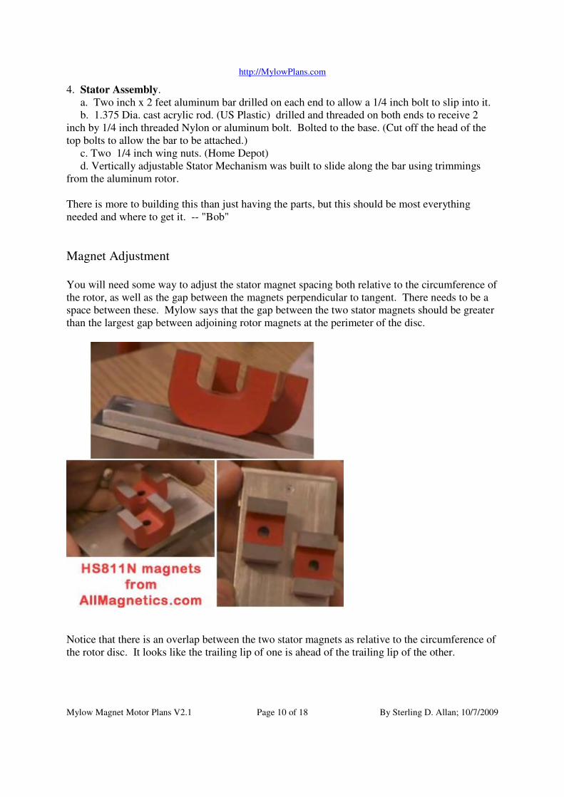
4. Stator Assembly.
a. Two inch x 2 feet aluminum bar drilled on each end to allow a 1/4 inch bolt to slip into it.
b. 1.375 Dia. cast acrylic rod. (US Plastic) drilled and threaded on both ends to receive 2
inch by 1/4 inch threaded Nylon or aluminum bolt. Bolted to the base. (Cut off the head of the
top bolts to allow the bar to be attached.)
c. Two 1/4 inch wing nuts. (Home Depot)
d. Vertically adjustable Stator Mechanism was built to slide along the bar using trimmings
from the aluminum rotor.
There is more to building this than just having the parts, but this should be most everything
needed and where to get it. -- "Bob"
Magnet Adjustment
You will need some way to adjust the stator magnet spacing both relative to the circumference of
the rotor, as well as the gap between the magnets perpendicular to tangent. There needs to be a
space between these. Mylow says that the gap between the two stator magnets should be greater
than the largest gap between adjoining rotor magnets at the perimeter of the disc.
Notice that there is an overlap between the two stator magnets as relative to the circumference of
the rotor disc. It looks like the trailing lip of one is ahead of the trailing lip of the other.

http://MylowPlans.com
Mylow Magnet Motor Plans V2.1 Page 11 of 18 By Sterling D. Allan; 10/7/2009
The N-S orientation of the two stator magnets will be the same, relative to the circumference of
the rotor disc. One direction will yield rotation in direction. Swapping them 180-degrees will
yield rotation in the opposite direction.
Screws
All screws in the assembly should be non-magnetic. You will need 3 to fasten bearing assembly
to rotor disc; and 4-10 to fasten stator assembly.
Glue
According to Mylow, an important principle here is that the magnets should touch the aluminum
if possible. Hence the use of hot glue is probably not a good idea as it creates too much of an
insulating factor between the magnets and the aluminum.
Crazy Glue for gluing the magnets to the aluminum.
Super Glue for gluing the rubber feet to the bearing base and the stator assembly feet.
Razor Blades
You will need something like a razor blade to scrape off the Crazy Glue when you remove
magnets to adjust them, or when they fall off for some reason.
VI. Assembly Instructions
(Your set-up may vary.)
1. Assemble the stator apparatus.
a. See Bob’s dimensions above.
b. The gap (horizontal parallel to the stator support bar) between the two stator
magnets in Mylow’s apparatus is around 7.35 mm (~0.290 inches).
2. Assemble the rotor bearing apparatus.
a. See Bob’s dimensions above.
3. Attach the bearing apparatus to the rotor disc.
a. Test the rotation of the disc without any magnets attached. It should spin freely.
b. Glue the rotor magnets in place, N up, using Crazy Glue (so they are easy to
remove and adjust if necessary). This is the crucial aspect of getting the motor to
work. See memo below regarding “Magnet Spacing Principles”.
Memo: Magnet Spacing Principles:
On May 16, Mylow gave the following instructions.
No two magnets are the same. Each magnet needs to be individually treated.

http://MylowPlans.com
Mylow Magnet Motor Plans V2.1 Page 12 of 18 By Sterling D. Allan; 10/7/2009
It isn't really plausible to post a template and follow it.
First, he glues one bar magnet down. He runs it under the stator to get its feel (I didn't quite
understand what is accomplished in this step).
Then he takes the second magnet. He holds it in place next to the first one with his thumb. He
then runs them under the stator to feel how much it cogs (cog = resistance). He then moves the
magnet one direction just a little bit, then he runs it by the stator again to see if the cog increases
or decreases. He keeps doing this until he finds that place where the cog goes away.
Mylow thinks getting some kind of non-magnetic clamp would help in this process.
Once he finds that no-cog spot, he then scribes a line with a pencil on the disc to mark the place
the magnet goes, and then glues the magnet in place. It is very important that you be able to glue
the magnet right at that position, so be sure your markings are such that you will be able to put
the magnet back in position.
As a double check, when the positioning is right, you should get that pendulum effect he shows
in one of his tutorial videos. And the pendulum effect (rocking back and forth when pushes, like
a spring) should take place directly under the stator, not to one side or the other.
He then repeats these steps with the next magnet; then the next.
As no two magnets are the same, no two spacings will be the same.
By the time he gets to the 5th magnet, he says he starts noticing a strange effect. The repulsive
effect of the first magnet as the magnets go toward the stator begins to dissipate. The repulsion
effect becomes a pull as the 2nd and 3rd magnets pass under the stator.
By the time you add the 6th magnet, if your bearing friction is low enough, you may get the
SMOT device effect that he showed on May 13.
He said that by the time he got to the 7th, 8th and 9th magnet, that there was a bu-bump
bounciness that began to come into the rotation. By the time he had the 12th magnet down, the
bounciness was very pronounced. A cog had come into the middle of the set of magnets.
He then glued in the 13th magnet and then removed the middle magnet, so there were now two
sets of six magnets, and the rotation became smooth.
(I presume that during all this time, from the 6th magnet on, he had acceleration if he let it go.
He did tell me the other day that he did get acceleration with the 9-magnet configuration he
showed in the caliper video.)
He cautions people that when they see this thing working, "It will change you." Make sure you
stay humble and dedicated to the benefit of humanity.

http://MylowPlans.com
Mylow Magnet Motor Plans V2.1 Page 13 of 18 By Sterling D. Allan; 10/7/2009
• One of the crucial aspects will probably be the relationship between the size of the rotor
magnets and the size of the stator magnets
• The elevation of the stator magnet over the rotor magnets does not appear to be nearly as
crucial as other variables.
FYI, here is the arrangement of magnets as Mylow had them on his disc May 12, 2009.
The measurements Mylow made with a caliper on May 14, which included three more magnets
to the right (a configuration that he said make the running smoother.
Gaps of 9 rotor mags -
from Right to Left (Note: inner gaps are not exact, he used other side of caliper)

http://MylowPlans.com
Mylow Magnet Motor Plans V2.1 Page 14 of 18 By Sterling D. Allan; 10/7/2009
mag# outer inner
------- 3 new mags -------
1
10.00mm 4.39mm
2
9.67mm 6.15mm
3
8.71mm 4.87mm
------- original 5 below: ----
---
4
8.95mm 5.38mm
5
9.39mm 6.48mm
6
9.11mm 6.50mm
7
9.96mm 5.45mm
8
9.43mm 5.90mm
9
Stator Gap: (parallel gap between horseshoe mags)
7.35mm
(7.12 was shown - after some caliper movement...)
(verbally stated off cam originally: 7.39mm & 7.31mm)
Stator Thin Overlap Gap: (gap between overlap of horseshoe poles)
13.16mm minus thickness of horseshoe pole
(he measured inside of one gap, and then the outside of a horseshoe
pole - so that thickness needs to be subtracted)
(minus about 8mm - don't have my digital caliper here)
equals about 5.16mm for Stator Thin Overlap Gap

http://MylowPlans.com
Mylow Magnet Motor Plans V2.1 Page 15 of 18 By Sterling D. Allan; 10/7/2009
Bear in mind that all magnets are not made the same, and some of the variance between magnets
could be Mylow’s gift to sense the differences and adjust the spacing accordingly.
See also http://peswiki.com/index.php/OS:MYLOW:Plans:Version_2.0:Instructional_Videos –
turns into version 2.1
VII. Operation
Once you have completed the assembly steps, you are ready to operate the motor.
1. Position the rotor assembly on a nominally flat surface with at least 6 inches of free space
around it. Give yourself plenty of room. Make sure there are not any magnetic objects in
the vicinity.
2. Bring the stator assembly into place so that the stator magnets are situated directly over
the center of a rotor magnet length.
3. Turn the rotor so it is at the beginning of a row of magnets. The stator should pull the
rotor magnets by, with enough flywheel and small enough cog to make it to the next set
of magnets, where the effect is repeated, gradually accelerating until an equilibrium
speed is reached.
http://MylowPlans.com
Mylow Magnet Motor Plans V2.1 Page 16 of 18 By Sterling D. Allan; 10/7/2009
a. If you have been successful, be sure to scribe a mark on your motor where each
magnet is so that you can replicate it if the magnets fall off somehow.
b. Take a video and post it at YouTube, and let us know, or post it directly on our
Replications page.
4. If this doesn’t work, you will need to try different rotor magnet arrangements. It took
Mylow three days to find the arrangement that worked. I recommend this order of
priority:
a. Try changing the distance between individual magnets. Make sure you have
some non-symmetry there.
b. Try changing the numbers of magnets per set.
5. Mylow said that the speed is controlled by the height of the stator magnets above the
rotor magnets.
6. To reverse direction of spin, reattach the stator magnets, flipping them 180 degrees.
(Note, Mylow said that it doesn’t work to run the motor with S upflip all of the rotor
magnets so S is up rather than down.
VIII. Principles & Variables
(In addition to what is presented above.)
The disc diameter is probably not a highly crucial component, but changing it will require
finding the proper spacing of magnets to work with the different circumference. You could try
tighter circumferences just by scribing a line on your rotating disc as a reference point.
You should try to go with weaker magnets for this replication. Stronger magnets will require
better engineering to prevent detachment of the rotor magnets.
Mylow said that you do not want to seek uniformly magnetized magnets for the rotor magnet.
Remember, non-symmetry is a key here.
We don’t yet know if the aluminum material in the rotor is required for operation. The Eddy
current phenomenon that arises when magnets are passed in vicinity by aluminum, creating a
braking effect, may be part of what makes this design work. Or it could be an impediment,
which if removed would take away the equilibrium speed phenomenon, causing the motor to
speed to destruction if no load is present. Mylow seems to think it is a requirement.
Once working, adding a Permeability Plate could augment the effect.
IX. Resources
• http://groups.yahoo.com/group/MYLOW-News - A newsletter for replicators.
• http://groups.yahoo.com/group/MYLOW_MagMo - email forum for those involved in
replicating and improving the technology
• http://MylowMagnetMotor.com – Open Source Project page

http://MylowPlans.com
Mylow Magnet Motor Plans V2.1 Page 17 of 18 By Sterling D. Allan; 10/7/2009
o http://peswiki.com/index.php/OS:MYLOW:Plans:Version_2.1
o http://peswiki.com/index.php/OS:MYLOW:Plans:Version_2.0:Instructional_Vide
os
o http://peswiki.com/index.php/OS:MYLOW:Videos
o http://peswiki.com/index.php/OS:MYLOW:Plans
o http://peswiki.com/index.php/OS:MYLOW:Plans:Version_2.0
o http://peswiki.com/index.php/OS:MYLOW:Latest – Project updates page
o http://peswiki.com/index.php/OS:MYLOW:Variants
o http://peswiki.com/index.php/OS:MYLOW:FAQ
o http://peswiki.com/index.php/OS:MYLOW:Replications – post yours here
o http://peswiki.com/index.php/OS:MYLOW:Forums
o http://peswiki.com/index.php/OS:MYLOW:Correspondence_with_Mylow
o http://peswiki.com/index.php/OS:MYLOW:Theory
o http://peswiki.com/index.php/OS:MYLOW:Related_Sites
• http://peswiki.com/energy/Directory:Magnet_Motors – Other designs
• http://peswiki.com/energy/OS - Other open source projects and resources
Credits:
Thanks to Don Jonsson for the graphic images. Thanks to “Bob” from Utah County for making
the rotor-stator assembly and shipping it to Mylow. Thanks to AllMagnetics.com for working
with us for a price break. Thanks to all you who support this project in your many ways. Most
of all, thanks to Mylow for his generosity in open sourcing these designs, and to Howard
Johnson for inspiring us all with his pioneering work in this area. Thanks to all the spouses who
have put up with our obsession with moving this technology forwards.

http://MylowPlans.com
Mylow Magnet Motor Plans V2.1 Page 18 of 18 By Sterling D. Allan; 10/7/2009
Contacts:
For an up-to-date list of contacts, see http://peswiki.com/energy/OS:MYLOW:Contacts for
project contact info, and http://pureenergysystems.com/contact/ for PES contact info.
Project Director Sterling D. Allan
4157 NW Pinion Cir.
Eagle Mountain, UT 84005
Email : <sterlingda {at} pureenergysystems.com>
phone: 801-407-1292 (Mountain time)
Mylow Correspondence Email : <mylow {at} pureenergysystems.com>
(Presently screened by Pmmtester on behalf of Mylow)


