N 7 3 33002 NASA TECHNICAL NASA TM X- 71462 MEMORANDUM CVJ < CO < THE ADVANTAGES OF THE HIGH VOLTAGE SOU\R ARRAY FOR ELECTRIC PROPULSION by Bernard L. Sater Lewis Research Center Cleveland, Ohio 44135 TECHNICAL PAPER proposed for presentation at Tenth Electric Propulsion Conference sponsored by the American Institute of Aeronautics and Astronautics Lake Tahoe, Nevada, October 31 - November 2, 1973 https://ntrs.nasa.gov/search.jsp?R=19730024269 2018-05-30T08:50:52+00:00Z
Transcript
N 7 3 3 3 0 0 2
NASA T E C H N I C A L NASA TM X- 71462M E M O R A N D U M
CVJ
<CO<
THE ADVANTAGES OF THE HIGH VOLTAGE SOU\R ARRAYFOR ELECTRIC PROPULSION
by Bernard L. SaterLewis Research CenterCleveland, Ohio 44135
TECHNICAL PAPER proposed for presentation atTenth Electric Propulsion Conference sponsoredby the American Institute of Aeronautics and AstronauticsLake Tahoe, Nevada, October 31 - November 2, 1973
Bernard L. Sater*National Aeronautics and Space Administration
Lewis Research CenterCleveland, Ohio 44135
ABSTRACT
The high voltage solar array (HVSA) offers improvements inefficiency, weight, and reliability for the electric propulsionpower system. The basic HVSA technology involves designing thesolar array to deliver power in the form required by the ionthruster. This paper delves into conventional power processesand problems associated with ion thruster operation using SERT IIexperience for examples. In this light, the advantages of the
JJ HVSA concept for electric propulsion are presented. Tests con-£; ducted operating the SERT II thruster system in conjunction with' HVSA are discussed. Thruster operation was observed to be normal
and in some respects improved.
INTRODUCTION
The intent of this paper is to point out the advantages ofthe High Voltage Solar Array (HVSA) for Electric Propulsion.The basic HVSA technology involves designing the solar array todeliver its power in the form required by the ion thrusterdirectly without intermediate power processing. In the conven-tional power system approach, the solar array provides power atrather low voltage. This makes power processing necessary forelectric propulsion since ion thrusters require power in manyforms but primarily at high voltage. The prime impetus of theHVSA concept lies in eliminating the losses, weight, and unreli-ability associated with conventional power processing. In anyion thruster mission, improvements in the specific weight,efficiency and reliability of the total power subsystem (source
*Technical Assistant to Chief, Power Electronics Branch
plus power processing) will enhance system performance. Therehave been several studies(1/2/3) sponsored by NASA-LewisResearch Center, of the HVSA concept. They were concernedprimarily with investigating the HVSA with power conditioningintegral with the panel which can provide regulated high volt-age (2 kV to 16 kV) at rather high power levels (15 kW). Theywere studied in the framework of a hypothetical direct broadcastTV satellite using ion thrusters to raise itself from a lowearth injection orbit to a synchronous altitude. The solararray could be configured to operate the ion thrusters asrequired and be reconfigured to power the TV broadcast trans-mission tube when on its synchronous station. In general thesestudies have concluded that HVSA's are feasible and that theycan out perform conventional power processing systems operatingfrom low voltage arrays. However the scope of these investi-gations were limited to the realm of high voltage and highpower aspects typical of the beam requirements of an ionthruster system. The imposed limitations of these studies willbe pointed out along with additional consideration of the otherrequirements of electric propulsion. In addition to thesestudies there has been experimental investigations of the basicregulation concepts of HVSA at NASA-Lewis Research Center(4)and Hughes Research Laboratories(5). This work further sub-stantiates the merits and feasibility of this technology andwill be briefly reviewed in order to present an overall prospec-tive of the HVSA status.
A new solar cell, the multiple junction edge illuminatedsolar cell (M-J Cell), will be described^). The M-J Cell wasdevised for high voltage, low current requirements such as theion thruster's accelerator and keeper electrodes and will alsofind application for sensor and control ,power.
A principle advantage of the HVSA for electric propulsionlies in that the characteristics of the solar cell and therequirements of the ion thruster are ideally matched. The solarcell is inherently a dc power source that is ripple free andcurrent limited while the ion thruster requirements are primarilyfor dc power of low ripple with limited current for protection.It is necessary to realize the short comings and problemsassociated with conventional power processing to obtain theserequirements or the disadvantages of conventional power process-ing, in order to fully appreciate the advantages of the HVSAfor electric propulsion. Because of the author's experience and
familiarity with the SERT II program it will be the basis forthis discussion. In early 1970 a "quick and dirty" test wasconducted in operating the SERT 11.Lion, thruster system' in 'Con-junction with solar array power. Thruster operation was ob-served to be normal and in some respect improved by the ripplefree nature of the solar array power. These tests and obser-vations will be discussed.
ION THRUSTER - POWER PROCESSING SYSTEM ASPECTS
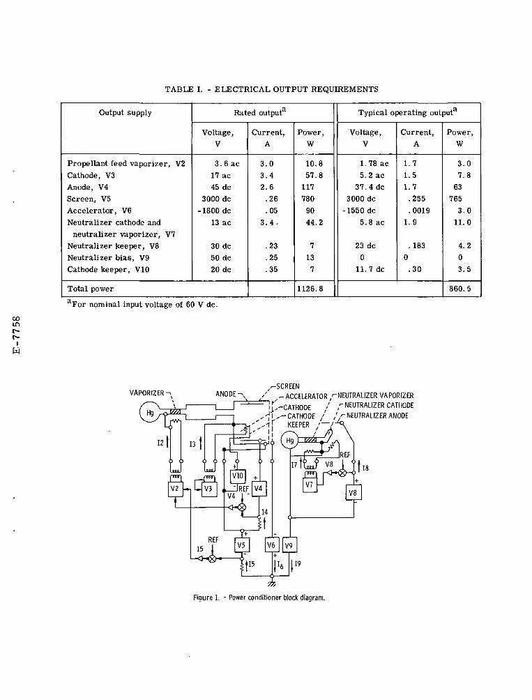
The block diagram of the SERT II ion thruster and powerconditioning (p/c) system is shown in Fig. 1. A completedescription of the SERT II ion thruster system was given byKerslake, et al.(?) and the power conditioning system wasdescribed by Hoffman, et al.(8)_ However for completeness,table I lists the rated electrical power outputs from theSERT II P/C for each of the nine supplies. Also listed arethe typical operating values for each supply for the nominalsolar array input of 60 V during full beam thruster operation.The solar array operating characteristics will be influencedby the P/C loads, radiation damage, temperature, and sun lineorientation. This imposes an input variation of 54 to 75 Vthat the SERT II P/C must satisfy the thruster requirements.
From a power processing viewpoint, ion thrusters presentan unusual combination of characteristics that make the crea-tion of a design for low weight, efficient, and reliable opera-tion difficult. The heaters (V2, V3, and V7) are low impedancedesigns and undergo rather large impedance changes from coldto hot. The keeper discharges (Vg and V]_Q) require a peak highvoltage for initiation and a smooth transistion to a lowervoltage operating condition. The bulk of the power is requiredin the form of high voltage (V5). Both positive (V5) and nega-tive high voltages (Vg) are present. Breakdowns and arcingwithin the ion thruster (V5 to Vg and V5 to ground) occur withextremely fast rise times. Many supplies must float at thepositive high voltage potential (V2, V3, V4 and V^Q). in additionthe plasma associated with the discharge will couple and effec^tively short supplies together. To bring a thruster up to oper-ating temperatures requires that the supplies be turned on ina certain sequence; called the preheat, propellant and operatemodes. Last, but not least, is the physical nature of the ionthruster in a highly complex process system. From a control
viewpoint its control elements are quite nonlinear, with longtime constants, transport lags, and strong interactions betweenprocesses. For example, the vaporizer heater power and flowrate are quite nonlinear with long thermal time constants.The propellant flow is subject to transport lags in the plumbingand thruster chamber thereby creating delays within the controlloops. And ripple in the anode discharge current, 14 reflectsstrongly in the beam current ripple, I5 (9^. This broad brushtreatment of the "nature of the beast" is to set the tone fordiscussion of problems associated with the conventional powerprocessing for ion thrusters.
CONVENTIONAL POWER PROCESSING
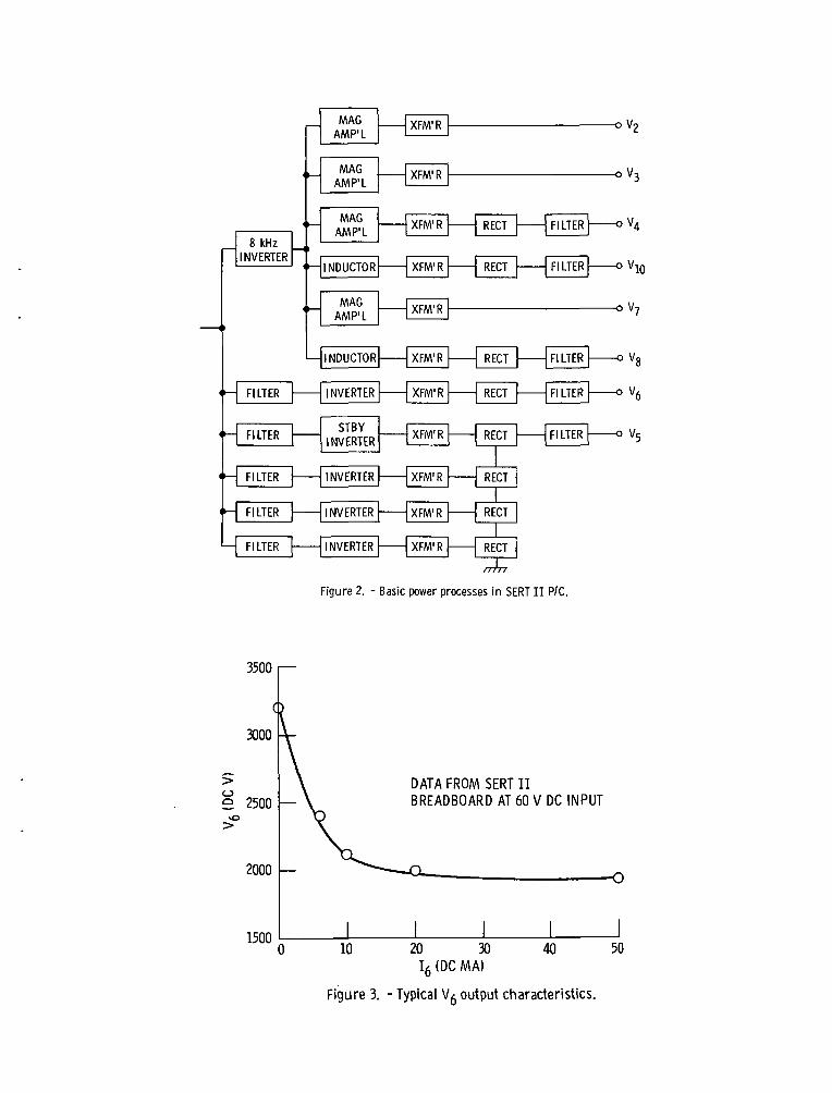
Conventional power processing for ion thrusters involvemany basic power processing functions. The processes utilizedin the SERT II power conditioning and control system shown inFig. 2 are typical and were primarily:
(1) Inversion - The process of converting dc power to acpower by switching devices.
(2) Transformation and dc Isolation - The process of con-verting ac power from one level to another either step up orstep down and/or providing dc isolation between input and output.
(3) Rectification - The process of converting ac power tounfiltered dc power.
(4) Filtering - The process of suppressing frequency oninput and/or output by passive energy storage devices.
(5) Power Modulation - The process of controlling powerfrom the source such that the output is maintained withindesired limits.
For SERT II power modulation was accomplished by PWM of anunregulated ac power by magnetic amplifiers. In addition, thereare the command control, feedback control and overload protec^tion processes.
As shown in Fig. 2 each of these power process functionsare essentially series operation as far as efficiency and reli-
ability are concerned. Each process, being imperfect, compoundsthe overall electrical efficiency and reliability. For example,if the process associated with V5 are each 98 percent effic-ient the overall efficiency would be approximately 90 percent.In a similar manner the overall reliability is effected by thereliability of each series function. In practice the efficiencyand reliability of each process will not be the same, with theinversion process usually the less efficient and reliable. Thereported efficiency of the SERT II P/C was 87 percent underrated conditions.^
In the following discussion of the SERT II P/C outputs, arather in-depth treatment of some of V^ supply design problemswill be given. In no way is this discourse intended to reflecta criticism of the SERT II p/c design that has been provensuccessful in its space mission. The rational for this being tomake the reader aware of typical design problems encountered inpower processing for ion thrusters. These functional designsubtleties encountered are difficult to explain in the convention-al concise manner of technical papers and reports and thus arenormally glossed over in most circuit descriptions. This leavesthe uninitiated reader with a vastly oversimplified technicalpicture. By realizing the short comings and problems associatedwith conventional power processing, one gains further apprecia-tion of the advantages of the HVSA concept for electric propul-sion. The HVSA concept does not involve power processes such asinversion, transformation, and rectification.
Screen (V5) Supply
The screen (V5) supply consists of three modified Jenseninverters(10) where each provides one third of the output power.The inverter transistors alternately switches each half of theprimary winding so generating an alternation current (ac) voltageacross the primary winding. This is transformed to the highvoltage (1000 V ac/module), rectified and filtered. The rectifiedoutputs are connected in series to provide the required +3000 V.Protection is simple in sensing when output current exceeds agiven amount and quickly shutting off the inverter for a shorttime interval. This technique interrupts the on set of an arcthat very likely may be self-sustaining if not interrupted. Forreliability, a fourth inverter can be commanded to operate in
the series string, if one of the other ^nverters fails. Thistechnique of partial redundancy does enhance the overall systemreliability with a small weight impact. In principle theoperation appears straight forward. However, when one getsdown to the nitty gritty of power processing design, things arenot so simple. For example, the transistors in the invertertypically turn on faster than they turn off and this overlapappears as a "short" on the dc input line. In the case ofSERT II, an inductor filter in series with the dc input limitedthe input rate of current rise in this interval. Transistorsrequire drive sufficient to handle its worst case extremedemands, that may be typified by starting at low input voltageinto its maximum output load while at its lowest operatingtemperature. Since transistor gain may vary 3:1 over itstemperature range, designing for worst case presents problemsin normal operation with excess drive currents. Excessivedrive in normal operation causes excess minority carriers inthe transistor which increases the turn off times and compoundsthe problem of overlap and efficiency.
The transformer appears on the surface to be a simpledevice, however, in the design of high voltage transformersfor inverters subtle characterisitcs are encountered. Trans-formers are the heaviest components in the P/C and in orderto decrease its size, the frequency must be increased with itsattendant increase in losses. Thus, efficiency and weight areopposing design relationships. Also, high voltages requiresadditional dielectric material between winding and layers makinga high voltage transformer weigh more than its same VA capacitylow voltage counterpart. In addition, the separation causesadditional reduction in mutual coupling of the transformer whichdecreases its regulation from a strictly turn ratio viewpoint.In order to convert the low voltage to high voltage there mustbe a large turns ratio between the input and output windings.The large number of turns and usual layer construction form arather large distributed capacitance in the secondary winding.This with the inherent, leakage reactances associated with theprimary and secondary windings results in an oscillatory LCcircuit that rings when excited with the fast rise and falltimes of the transistor. This ringing causes high peak inputcurrent and transistor dissipation in this interval along withthe possibility of the output filter being charged to the highpeak voltages after rectification under light load conditions.
In addition, for self oscillating inverters of the Jensentype where the collector to collector voltage is used forfeedback drive, a high frequency inverter operation modecould result under certain overload conditions because ofthe reflected high frequency characteristics of the trans-former. The fast rise times associated with breakdowns andarcs with ion thruster operation requires a grouded shieldbetween any output winding operating at the high voltagepotential of V5. The grounded shield terminates the dis-tributed capacitance in the output winding that would normallybe coupled to the input winding and provides an effectiveshunt for the electrostatic energy being discharged during thetransient. Without a grounded shield, these transients wouldbe coupled electrostatically from output winding to the inputwinding and the possibility of failure in the transient pronesemiconductor circuits would be high. This grounded shieldalso increases the separation between the windings. Low coreloss, high permeability magnetic core materials, such as80 percent iron - 20 percent nickel, exhibit a ratchetingphenomenon where the excercised B-H loop is only conditionallystable around its center but will drift towards on of itsstable equilibrium points, B , residual flux state.(H) Thisis caused not only by slight dc unbalance in the circuit dueto saturation voltage (Vcesat), tur-n on (ton), etc. of transistorsbut switching transients can intiate the phenomenon. A trans-former core that has ratcheted to one of its saturation portionsof the B-H loop will result in a high current spike in one ofthe inverter transistor near the end of that half cycle ofoperation.
Shutting off the transistor under this condition causeshigh peak power dissipation and undue stress. In SERT II theseries input inductor filter effectively limited the rate ofrise in current to safe levels during this interval. This fixwas necessary even with the use of D-U laminations in the trans-former core since the effective air gap was too small to avoidthe problem.
In addition, a limited discussion of certain salient prob-lems associated with some of the other supplies follows. Thisis included for background purposes since it will be shownlater that the HVSA concept avoids these characteristic prob-lems.
Accelerator (Vg) Supply
The Vg supply has its own inverter-transformer similarto that employed in the V5 supply. This supply's transformerwinding ratio is the highest of all and the aforementionedproblems of ringing in the transformer results in poor inherentregulation in the rectified output voltage under light loadconditions as shown in Fig. 3 for the SERT II preliminarybreadboard. In SERT II this problem was endured rather thanburden the output with a bleeder to dissipate the transientenergy and suffer the attendant losses. As one can see fromFig. 3 to obtain load regulation of approximately 5 percentwould require a bleeder of 10 mA with a dissipation of 20 W.
Anode (V4) Supply
The anode (V̂ ) supply receives power from the master8 kHz inverter which also powers the remaining supplies. Amagnetic amplifier is employed to modulate the ac power priorto transformation, rectification and filtering as shown inFig. 2. This supply along V2, V^, and V-^g floats at thepositive high voltage (Vs) potential. Normally sensing andcontrols are done on the input side of the output transformersto minimize circuitry that must operate at the HV potential.This requires circuitry to compensate for temperature and loadeffects. In instances such as in the V4 and V10 suppliesthe rectifiers and filters must be on the high voltage side.Here it is necessary to recognize that the V5 high .voltagebreakdowns are extremely fast and essentially instantaneousfor all. practical purposes.
In Fig. 4 the function of the capacitor, CA across therectifiers is to absorb the transient energy associated with thedistributed capacitance, CD in the transformer, wiring, andcomponents when the thruster arcs. For instance, without thiscapacitor a sudden-drop in the V5 potential due to a fastrising arc could result in high inverse voltage stress on therectifiers. Since the distributed capacitance shown schematicallyin Fig. 4 would likely maintain its charge at the V5 potentialprior to the arc for some finite interval of time.. The addedcapacitor, CA is sized to absorb all this distributed capacitanceenergy while permitting only a safe voltage rise that is wellwithin the rectifier's PIV ratings.
An important requirement for the arode (V4) supply is lowripple content in its output voltage. There are severalparamount reasons for this: (1) voltage ripple modulates thedischarge current within the ionization chamber and this modu-lation can be strongly observed in the main ion beam^9); and(2) the propellant utilization of the ion thruster is quitesensitive to the potential of the Anode supply.(''
In the SERT II case, the V4 supply was set to be anominal 37.0 V with ±4.5 percent peak ripple allowed. Design-ing for less ripple is highly desirable, but would requireadditional filtering and its attendant weight increase. Onemust recognize the difficulty in designing for low ripplecontent in a low voltage, high current dc output filter suchas V4's when the power is modulated by PWM techniques, yetis light weight, efficient, and reliable. This discussion isintended to be a brief synopsis of conventional power processingfor ion thruster problems. In view of the above remarks aboutthe nature of the ion thruster characteristics and the powerprocessing design problems, it is no wonder that power process-ing for'ion thrusters have proven complex, inefficient, andcostly to develop. In fact, many of the advantages of theHVSA concept for electric propulsion are afforded because ofthe disadvantages associated with conventional power processing.The HVSA concept does not involve many of the basic processessuch as inversion, transformation, and rectification thatextracts their toll in weight, efficiency and reliability.
INHERENT CHARACTERISTICS OF HVSAFOR ELECTRIC PROPULSION
As mentioned in the introduction, the prime impetus for theHVSA concept lies in eliminating the losses, weight, and unreli-ability associated with conventional power processing. The basicHVSA technology involves designing the solar array to deliverits power directly in the form required by the ion thruster.
If one examines the physical processes within the ionthruster, all are inherently dc in nature. The thermal flow, dis-charges, the ionization, acceleration, and neturalization of theion are all dc processes.
10
Although the thermal flow for all heater elements areunidirectional, heaters could be ac or dc operated since onlyelectrical heating power to reach thermal conditions arerequired. In conventional power processing, such as SERT II,ac is applied to the heaters for efficiency reasons. To obtaindc would necessitate the addition of rectifiers with itsattendant losses. DC operated heaters have advantages whencompared to ac powered heaters. For example, the line inductanceof the wiring limits the upper ac operating frequencies that canbe used to effectively transmit power and the power factorassociated with the line reactances reflected to the invertereffects its efficiency.
In certain instances, operating the inverters at higherfrequencies and rectification of the ac to dc power the heatersresults in weight reduction that may offset the increase losses.At the present time, Hughes Research Labs is comtemplating theuse of dc for heater in the design of the 30 cm ion thruster
c\">\power processing. \ •*-*•'
Another factor one can observe is all the supplies for theion thruster are current limited in one form or another. Theheaters employ magnetic amplifiers to limit the current undercold impedances or short circuits. The keeper discharges arecurrent limited by the series inductor on the inverter side oftheir output transformer prior to rectification and filtering.This provides the soft I-V characteristics for ignition of thedischarge and stable operation. The Anode discharge also mustbe current limited to protect the ion thruster. When the thrusterarcs and the HV supplies are momentarily shut off, the plasmacurrents in the discharge can increase considerably due to theloss of the .extraction of ions from the discharge by the fieldoptics associated with the screen and accelerator electrodes.Current limiting the Anode discharge limits the additional heat-ing and possible damage that would occur within the ion thrustersand also makes the plasma less dense and hence easier to re-establish the HV potential to the screen and accelerator. Inaddition it is necessary to limit current by interrupting thebreakdown or arc currents associated with the screen and accel-erator. Without this provision an arc occurrence could be selfsustaining and continuous. The V5 and Vg supplies, however,are necessarily designed for fast shutdown in order to protectthe inverter transistors. It is very likely that sensitive andfast acting overload sensing and tripping circuits as used in
11
SERT II, would give the appearance of more frequent break-downs and arcing than really exists within an ion thruster.
Now turning our attention to the source of power forall practical electric propulsion missions - the solar cell.This device has ideal characteristics for the type of loadsexhibited by the ion thruster. The solar cell is inherentlya ripple free dc power source that is current limited. Theseare the very characteristics that one tries to achieve in thedesign of conventional power processing for ion thrusters.
The solar cell is rugged and can operate in three I-Vquadrants as shown in Fig. 5. Power is delivered by thesolar cell while operating in quadrant I which is its normalmode. In addition, the solar cell can safely dissipatetransient power, if required, in the forward or reverse biascondition as represented by quadrant II and IV respectively.
In principle the transition from a low voltage solararray to a HVSA is a straight forward task. One connects alarge number of solar cells in series to achieve the highvoltage and a few in parallel to satisfy the current require-ments, instead of the converse as in a conventional low voltagearray.
As will be shown later, the preferred method for regulationof a HVSA is by shorting out solar cells in excess of thatrequired to maintain its output. This is essentially a non-dissipative technique in that a "shorted" solar cell dissipatesno more power than an unloaded solar cell, thus presents nothermal stress on the array. Figure 6 shows a typical solarcell I-V, power, and temperature relationships in a graphicallymanner. The solar cell operates at the lowest temperaturewhen it is delivering maximum power which is consistent withthe conservation of energy principles. Likewise the tempera-ture of operating in the open circuit or short circuit mode isessentially the same. In essence, the solar cell's inherentcharacteristics of a rugged dc power source that is ripple freeand current limited are ideally matched with the intrinsicrequirements of the ion thruster. From a systems viewpoint, ifthe source and load are compatible then there is no requirementfor power processing, per se.
12
HVSA STUDIES AND LIMITATIONS
In 1969, NASA-Lewis Research Center sponsored threestudies of the HVSA Electrical Configuration.^'2'3^ Theobject of these studies were to define: (1) conceptionaldesigns of electrical configurations for HVSA with integralpower conditioning; (2) problems associated with developmentof such electrical systems; and, (3) efforts associated withthe resolution of the problems identified by the studies.
For study purposes, the array application postulatedwas supplying power to ion thrusters to raise a spacecraftfrom low orbit to synchronous orbit and then reconfigure topower high frequency electron tubes for TV broadcasting.Briefly the most significant system requirements and studyguidelines were:
(1) The array must be capable of delivering 15 kW ofuseable power at one voltage level or up to six differentvoltage and power levels in the voltage range from 2 kV to16 kW.
(2) The electrical configuration should have capabilityof delivering power to loads over the widest practical rangeof voltage and current.
(3) The array must be capable of being configured to anyof its physically realizable states by ground command.
(4) The load voltage or load current should be regulatedto +0.1 percent using an on-board computer control.
(5) The array design and electrical configuration shouldprovide a reliability after deployment of 0.99 probability ofdesign power at the end of 5 years with a 90 percent confidencelevel.
For the basis of these studies, the array construction,assumed for design estimates as to weight and size, is thatgiven in the 30 W/lb Roll-up Solar Array Feasibility Study. ̂ -L3^
In parallel with these investigations the space plasmaenvironment interactions with the HVSA were being examined;however, discussion of these aspects are beyond the scope of thispaper.
13
In general these studies concluded that HVSA's arefeasible and can out perform the conventional power process-ing system operating from low voltage array. However, thescope of these investigations were limited to the realm ofregulated high voltage and high power typical of the beamrequirements of an ion thruster which represent 0.85 to 0.9of the total power requirements. For an electric propulsionmission, where reconfiguring is not required, the HVSA canprovide regulated power for the main beam with a systemperformance estimate of 0.6 to 1.0 Ib/kW and an efficiency of0.99 to 1.0. (2) This is highly favorable in comparison to theconventional power processor performance of 8 to 12 Ib/kW andan efficiency of 0.9 to 0.94.
The design goals of 0.99 reliability specified for thesestudies could be met by incorporating a large number of by-pass diodes to provide an auxiliary current path in the eventof an open circuit solar cell failure. This reliabilityfigure is much higher than presently achieved in the conven-tional power processing system.
In brief, these studies show distinct advantages thatthe HVSA concept offers for electric propulsion in weight,efficiency and reliability even if only the main beam require-ments were considered.
PRESENT STATUS OF HVSA
The studies identified problem areas and defined theeffort necessary to develop the switching, sensing, and controldevices required for integral regulation and reconfiguration onthe array. It was originally intended that additional NASAsponsored effort to breadboard, develop and verify the designconcepts in a system evaluation would follow. Unfortunatelythis did not materialize as planned but some related activitieshave evolved that still makes this a viable technology forelectric propulsion.
A new photovoltaic device, the Multiple Junction, EdgeIlluminated Solar Cell (M-J Cell)<6> was devised to fulfillthe need for high voltage, low current loads represented bythe accelerator Vg and the high voltage ignition requirementsof the keeper electrodes, Vg and V10. In addition this cell
14
would find application in providing isolated power for controlsand sensors. Devices developed for a flight test in the MINXExperiment (Miniature High Voltage Array Interaction Experi-ment) (16) in early 1974 on the SPHINX spacecraft have 96 seriesconnected P-N-N+ junctions in a 2 cm by 2 cm cell, whereeach individual solar cell junction has an area of approximately0.04 cm2. Figure 7 shows the M-J Cell's construction andtypical performance compared to a conventional cell. The MINXarray shown in Fig. 8 is a series connection of 36 M-J Cells.The total array voltage is 1100 V dc (80° C) with approximately1 mA output capability. It is likely that the MINX arrayconfiguration would be representative of a practical acceleratorsupply. Also on the MINX experiment a hybrid micro-electronicssolid state relay is used to control tha output of a group of4 series connected M-J Cells. The requirements of this solidstate relay were quite severe and maybe representative of thatrequired for the HVSA. It is significant that this smalldevice packaged in a TO-116 package provides 5000 V coronafree isolation and survives 1000 thermal cycles from -120° C to+800 c^17) .
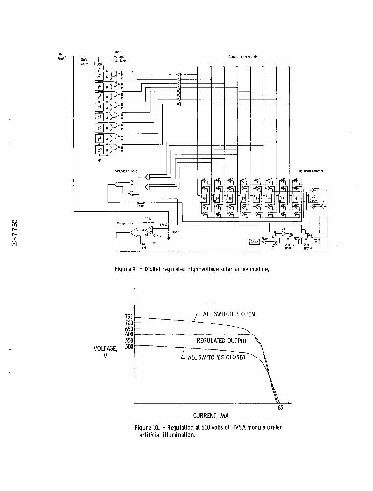
In addition to ..these new developments, several experimentalinvestigations of the weighted binary digital regulation conceptof an actual solar array were pursued by NASA-Lewis ResearchCenter(4) and Hughes Research Labs.(5} This work, utilizingoptoelectronics techniques for voltage isolation, further sub-stantiates the merits and feasibility of the HVSA. For highvoltage, this technique of regulation appears simple, efficient,and reliable. For completeness a brief description of theNASA tests follows, however, the reader should refer to thereferenced material for more detail. In Fig. 9 a schematic ofthe test array is shown. This array is divided into two sections.A 500 V unregulated section and a 255 V weighted binary regulatedsection. The 255 V regulated section of the solar array wastapped at voltage levels equivalent to the binary weight system(i.e., 2°, 21, ....27). The variable voltage from 0 to 255 V in1 V increments is obtained with this binary voltage tap configu-ration.
The unregulated 500 V solar a-ray section was placed inseries with the 255 V regulated solar array section for a totalarray output capability of 755 V at 50 mA.
15
Regulation of 0.175 percent was obtained with thisarrangement and an I-V plot taken is shown in Fig. 10.Basically any voltage +1.0 V can be obtained between thetwo extremes shown for all switches open and all switchesshorted. Closed loop control was achieved by an up-downcounter operating from the signal derived in comparing theactual voltage output with a reference voltage.
Another experiment, shown schematically in Fig. 11demonstrated a Pulse-width modulation (PWM) technique. Inthis configuration, power is modulated in a PWM fashion bythe transistor shorting the 300 V and 0.5 A solar arraysupplying two series connected lamps as a load. This experi-ment was operated at 100 kHz rate with modulation from 0 to100 percent, yet the output transistor required no heat sinkwhich is an indication of its efficiency.
A basic switch, employing photo coupled light emittingdiodes (LED) and transistors, shown in Fig. 12, was bread-boarded and demonstrated as being feasible for computercontrol and hybrid microminiaturization. Turn on and turnoff is accomplished by pulses from the computer output tothe LED's coupled to the appropriate photo-transistors.Briefly its operation follows: A turn on pulse into LED2drives photo transistor PT2 on, which in turn pulls currentthrough LED^ and provides drive to PT-|_. PT^ provides basedrive and turns on transistor, Q]_. If Q-^ is driven into ornear saturation (full on) current will continue to flow inLED]_ through diode 02 even after the turn on pulse terminates.Therefore, an. on pulse in LED2 will cause transistor, Q^_ tolatch on via LED-^ and PTr^ and remain on until (1) a turn offpulse into LED3 turns on photo transistor, PT-^ and shunts Q-,base drive momentarily allowing it to turn off, or (2) for anyreason transistor Q^ pulls out of the saturation region, i.e.,due to overload exceeding base drive capability, partial shadow-ing of the drive solar cells lowing the base drive to insuf-ficient levels, etc. This self protection feature would benecessary to protect a hybrid package because of its limitedpower dissipation capability and lack of heat sinking on anarray. In any tests it is probable that instances of partialshadowing and overloading would be commonplace.
Under contract with NASA-Lewis Research Center, HughesAircraft Co. has fabricated a modular high voltage solar cellpower generating systemd8) that will be a test bed for futureHVSA development activities.
16
OPERATION OF SERT II ION THRUSTER SYSTEMWITH SOLAR ARRAYS
In early 1970 a series of "quick and dirty" tests wereconducted using the SERT II ion thruster system (includingP/C) in conjunction with solar arrays. This testing wasproposed and conducted within a three week period in orderto take advantage of SERT II hardware availability and avacuum chamber prior to being modified for another program.Because of expediency, short cuts were necessary and minimumdata was recorded. (Also at the time it was felt that thistype of activity would be continued and refined; howeverthis was not the case.) Although the tests and techniquesappeared crude, the observations noted are valid and will bediscussed.
The solar cell arrays available were: (1) 12-SERT IIsolar array panels (28 V at 0.5 A each) that could easilybe modified to provide a wide variation of voltage and cur-rents up to 168 W maximum; (2) 22-1 ft2 fiber glass HV panelswith 234 series connected 1x2 cm.2 solar cells on each panel(117 V at 35 mA each). An array of lamps was set up and withrectified 3$, 60 Hz power controlled by a variac, the "sun"source was created in the lab. Since this was not sufficientsolar array power to operate the entire SERT II thruster sys-tem, it was done piece-meal as follows:
Vaporizer, V2 - A section of the array was configured tomatch its maximum requirements. Since the vaporizer is feed-back controlled by Anode current, I4 during "propellant"mode and the screen current, I5 during "operate" the simplesttechnique for control was implemented. The analog signalinside the SERT II P/C mechanized to control the V2 magneticamplifier was used to modulate a 10 V pre-focused light bulbinstead. This light bulb was optically coupled to a transistorwith a hole in its case using black opaque heat shrink plastictubing. This technique provided the necessary high voltageisolation between the analog signal at ground and the tran-sistor control on the solar array floating at the V,. potential.The circuit design was such that the I2 - 15 control loop gainrequired for stable thruster operation was maintained. Normaloperation of the thruster was observed in this test.
Cathode, V% - A section of the array was configured toproviOTe its maximum requirements for "preheat" and "propellant"modes and a tap was made in the array to provide normal"operate" power. A high voltage ceramic vacuum relay was used
17
to switch between modes by picking up a control signal fromthe P/C. Normal operation of the thruster system was observed.
Cathode Keeper, V]n - Two arrays were configured and '"or" together with diodes to provide the I-V characteristicsshown in Fig. 13. The HV modules provided the 400-500 V at35 mA and the SERT II panels cells are configured to provide0.5 A which couldn't be easily modified. Therefore, gumbacked tape was used to cover some of the cells to providethe 0.3 A required at 30 V.
Neutralizer, V7 and VR - The composite arrays configuredfor V]_o was used for the Vg keeper supply but modified forthe 200 mA maximum current requirements and an additionalarray was configured to provide the maximum Vj heater require-ments. A shunt regulator circuit shown in Fig. 14 was used toprovide the proper Vg-I7 feedback gain relationships. In thetest the neutralizer was operated entirely off solar arraypower and low ripple operation was observed. In Fig. 15 scopephotos of neutralizer keeper's voltage and current, Vg and Igare shown for (a) operation with the SERT II power conditioner,and (b) operation directly off the solar array. We can see in(a), the ripple associated with the conventional power process-ing systems. It is 16 kHz ripple that results by rectifica-tion and filtering the J?WM 8 kHz master inverter power. Todecrease its magnitude additional filtering weight would berequired. One should observe the ripple free nature of solararray power shown in (b). The plasma noise however can beobserved in these photos and it is quite possible that it canbe effectively filtered at the thruster to eliminate conductivepropagation of these frequencies along the lines to the source.
Accelerator, Vg - The high voltage modules were configuredto provide the necessary -1800 V. Several by-pass diodes wereadded to provide transient paths for a V5 to". V6 arc. Forcontrol only on-off operation was required and was accomplishedusing a high voltage ceramic vacuum relay operated with a controlsignal from the SERT II P/C. Normal operation was observedand no problems were noted with arcing. However, it should benoted that this direct.'HVSA hookup provides regulation,inherently as good as the solar array, that is not compromisedby the power processing idiosyncrasies as was shown in Fig. 3for the SERT II P/C.
18
Anode, V4 - This supply was configured to match, themaximum requirements and, for regulation, a weighted binaryswitching arrangement was introduced. Only three switcheswere necessary and manually operated high voltage ceramicvacuum relays were employed. The inherent ripple freenature of the solar array power was again observed as one cansee in Fig. 16. Here scope photos show, (a) the V4 and 14discharge ripple with the SERT II P/C- and (b) the V4 and14 discharge with solar array. Again the plasma noise ofthe discharge can be noted. Unfortunately these photos havedifferent time and amplitude scaling that makes direct com-parisons inconvenient.
Screen, V5 - Insufficient solar array was available tooperate the entire beam; therefore 300 V at 0.5 A of SERT IIarrays were connected in series with the existing V5 -supplywithin the SE-RT II P/C. This was connected in place of thestandby module and was floated to the normal V^ potential.It was found that a relay was necessary to "short" this arrayafter an arc to interrupt the 15 .current so that the P/Ccould reestablish the high voltage. This was done with ahigh voltage ceramic vacuum relay using the normal overloadshutdown signal within the P/C.
In summary these test testify to the feasibility ofoperating ion thrusters using the HVSA concept. No problemswere noted with arcing. In fact, induced arcs and shorts ofall combinations normally required for the SERT II P/C designwere purposely subjected to the solar arrays. The ripplefree power from the solar array is an additional benefit ofthe HVSA. Low ripple in the discharge supply V4 shouldenhance the ion thruster's operation for several reasons:(1) The discharge current modulates the beam current(9) there-fore, less ripple is more desireable; (2) the propellantutilization of the thruster system is very sensitive to thedischarge potential^) thus, low ripple may reflect an increasepropellant utilization. In addition, (3) the cathode sputteringis sensitive to the discharge potential^) and low ripple maylikely provide an increase lifetime.
19
ADDITIONAL CONSIDERATIONS AND CONCLUSIONS
The HVSA configurations as discussed here imposespenalties for ion thrusters systems. If one assigns aseparate dedicated array for each thruster load requirementthen each array as a minimum must be sized to furnish themaximum worse case load condition. In table I, the ratedP/C output reflects this maximum requirement for the SERT IIion thruster whereas the typical operating output require-ments are considerably less. For SERT II, the maximum ratedconditions are 1126 W which represent a 30 percent oversizepenalty for a dedicated HVSA when compared to the 860 Wtypical operating conditions. This would represent a poorlymatched HVSA system.
Fortunately there are system tradeoff considerationsthat would allow one to design a better power matching HVSAsystem. For example, considering the heaters V2 and V3are operated at their maximum levels only until the dischargeV4 has been established permits the possibility of sharinga portion of the array or a semi-dedicated HVSA system.
There are some functions that conventional power process-ing techniques can perform better than the HVSA concept as nowenvisioned. This lies in it being able to provide power con-version. For example, peak power tracking on an array tocharge batteries or capacitors is accomplished readily inconventional power conversion but would require an infinitereconfigurable solar array to use HVSA concepts.
Systems studies have not been fully investigated, but apractical HVSA system for an electric propulsion missionwould likely be comprised of a combination of HVSA and con-ventional power processing techniques. One could, for example,take advantage of HVSA concept to supply the main beam, V5and discharge, V4 directly from the array, and likewise usingM-J Cells for the accelerator, Vg, while using conventionalpower processing techniques for the other supplies. For theSERT II example, this would represent approximately 95 percentof the thruster"s typical requirements and would substantiallyimprove the systems performance in terms of weight, efficiency,and reliability.
20
Although considerable study and development remains to bedone, the work described in this paper demonstrates the tech-nical feasibility of the HVSA concept for electric propulsion.
CONCLUSIONS
The HVSA offers improvements in efficiency, weight andreliability for the electric propulsion power system. Theinherent characteristics of the solar array's ripple free andcurrent limited dc power ideally match the intrinsic require-ments of the ion thruster. Tests conducted on the SERT II ionthruster system in conjunction with direct solar array powerverify the feasibility of the technology and in some respectsthe enhanced ion thruster's operation. A practical HVSAsystem for electric propulsion would likely be comprised ofa combination of HVSA and conventional power processingtechniques.
REFERENCES
1. Springgate, W.F., "High Voltage Solar Arran ElectricalConfiguration Study," D180-10037-1, Apr. 1970, Boeing Co.,Seattle, Wash.
2. Herron, B.C., Creed, D.E., Ophorden, R.W., and Todd, G.T.,"High Voltage Solar Array Study,'! NASA CR-72724, July1970, Hughes Aircraft Co., El Segundo, Calif.
3. Ebersole, T., Hayden, J.H., Rasmussen, R., and Wiener, P.,"Study of High Voltage Solar Array Configurations withIntegrated Power Control Electronics," Rep. 70SD4256,NASA CR-72725, June 1970, General Electric Co.,Philadelphia, Pa.
4. Triner, J.E., "A Digital Regulated Solar Array Power Module,"TM X-2314, 1971, NASA, Cleveland, Ohio.
5. Herron, B.C., Bayless, J.R., and Worden. J.D., "High VoltageSolar Array Technology," Paper 72-443, Apr. 1972, AIAA,New York, N.Y.
6. Sater, B.L., Brandhorst, H.W., Jr., Riley, T.J., andHart, R.E., Jr., "The Multiple Junction Edge IlluminatedSolar Cell," proposed for presentation at the IEEE 10thPhotovoltaic Specialist Conference, Palo Alto, Calif.,Nov. 13-15, 1973.
21
7. Kerslake, W.R., Byers, S.C., and Staggs, J.F., "SERT IIExperimental Thruster System," Paper 67-700, Sept. 1967,AIAA, New York, N.Y.
8. Hoffman, A.C., Briggs, R.W. , Swiderski, E.F., Bauer, S.F.,and Weger, R.M. , "Power Conditioning Development for theSERT II Ion Thruster," Proceedings of the 4th TntersocietyEnergy Conversion Engineering Conference , AICLE, 1969,pp. 975-986.
9. Serafini, J.S., and Terdan, F.F., "Plasma Fluctuation ina Kaufman Thruster," proposed for presentation at theAIAA 10th Electric Propulsion Conf . , Lake Tahoe, Nev.Oct. 31-Nov. 2, 1973.
10. Jensen, J.L., "An Improved Square-Wave Oscillator circuit,"IRE Transactions on Circuit Theory, Vol. CT-4 No. 3,Sept. 1957, pp. 276-279.
11. Barker, R.C., "Magnetization in Tape-Wound Cores," Paper60-873, Nov. 1960, AIEE, New York, N.Y.
12. Allen, R.D., Williams, R.E., Lake, B., and Wellman, A.J.,"Feasibility Study, 30 Watts Per Pound Rollup Solar Array,"Rep. 40067-4, NASA CR-97205, June 1968, Ryan AeronauticalCo. , San Diego, Calif.
13. Springgate, W.F., and Damn, H. , "High Voltage Solar ArrayStudy," D2-121734-1, NASA CR-72674, 1969, Boeing Co.,Seattle, Wash.
14. Knauer, W. , Bayless, J.R., Todd, G.T.:, and Ward, J.W.,"High Voltage Solar Array Study," NASA CR-72675, May 1970,Hughes Research Lab. , Malibu, Calif. .
15. Riley, T.J., Triner, J.E., and Sater, B.L., "A MiniatureHigh Voltage Plasma Interaction Flight Experiment -Project MINX," proposed for presentation at the IEEE10th Photovoltaic Specialist Conf., Palo Alto, Calif.,Nov. 11-13, 1973.
16. Sater, B.L., Riley, T.J., and Janssen, W. , "Developmentof a Hybrid Microelectronics Solid State Relay for 2500Volts Isolation and -120 C to 80 C Thermal CyclingRange , " IEEE Power Electronics Specialist Conference,Pasadena, Calif., June 11-13, 1973.
17. Levy, E./Jr., and Opjorden, R.W., "High Voltage Solar CellPower Generating System," proposed paper for the IEEEPhotovoltaic Specialist Conference, Palo Alto, Calif.,Nov. 13-15, 1973.
TABLE I. - ELECTRICAL OUTPUT REQUIREMENTS
Output supply
Propellant feed vaporizer, V2Cathode, V3Anode, V4Screen, V5Accelerator, V6Neutralizer cathode and