This edition of NFPA 31, Standard for the Installation of OilBurning Equipment, was prepared by the Technical Committee on Liquid Fuel Burning Equipment. It was issued by the Standards Council on January 27, 2006, with an effective date of February 16, 2006, and supersedes all previous editions.
This edition of NFPA 31 was approved as an American National Standard on February 16, 2006.
Origin and Development of NFPA 31
Oilburning equipment standards date from 1902, when they were issued by the National Board of Fire Underwriters. Subsequently, the project was turned over to the NFPA and a completely revised edition was first presented to the Association in 1913. The responsibility for this standard is now that of the Technical Committee on Liquid Fuel Burning Equipment. Revised editions have been issued in 1948, 1951, 1953, 1955, 1956, 1957, 1959, 1961, 1963, 1964, 1965, 1968, 1972, 1974, 1978, 1983, 1987, 1992, 1997, 2001, and 2006.
The 1997 edition of NFPA 31 incorporated the following major amendments to the previous edition:
Editorial revision of Chapter 1, General, to effect editorial improvement and to comply with NFPA's Manual of Style
Numerous amendments to the definitions in Section 1.6, Definitions, to eliminate inconsistencies with NFPA 97, Standard Glossary of Terms Relating to Chimneys, Vents, and HeatProducing Appliances
Numerous amendments to the requirements for chimneys and chimney connectors in Section 1.11, formerly Section 1.7
New requirements for termination of flue gas venting systems in 1.12.3, Termination of Venting Systems
A complete revision of Chapter 2, Tank Storage
Copyright NFPA
A new version of Table 4.4.1.1, Clearances to Combustible Materials
A complete revision of Chapter 5, Installation of Heating and Cooking Appliances
A new Appendix D, Considerations for Combustion Equipment Firing Alternative (Nonpetroleum) Fuels
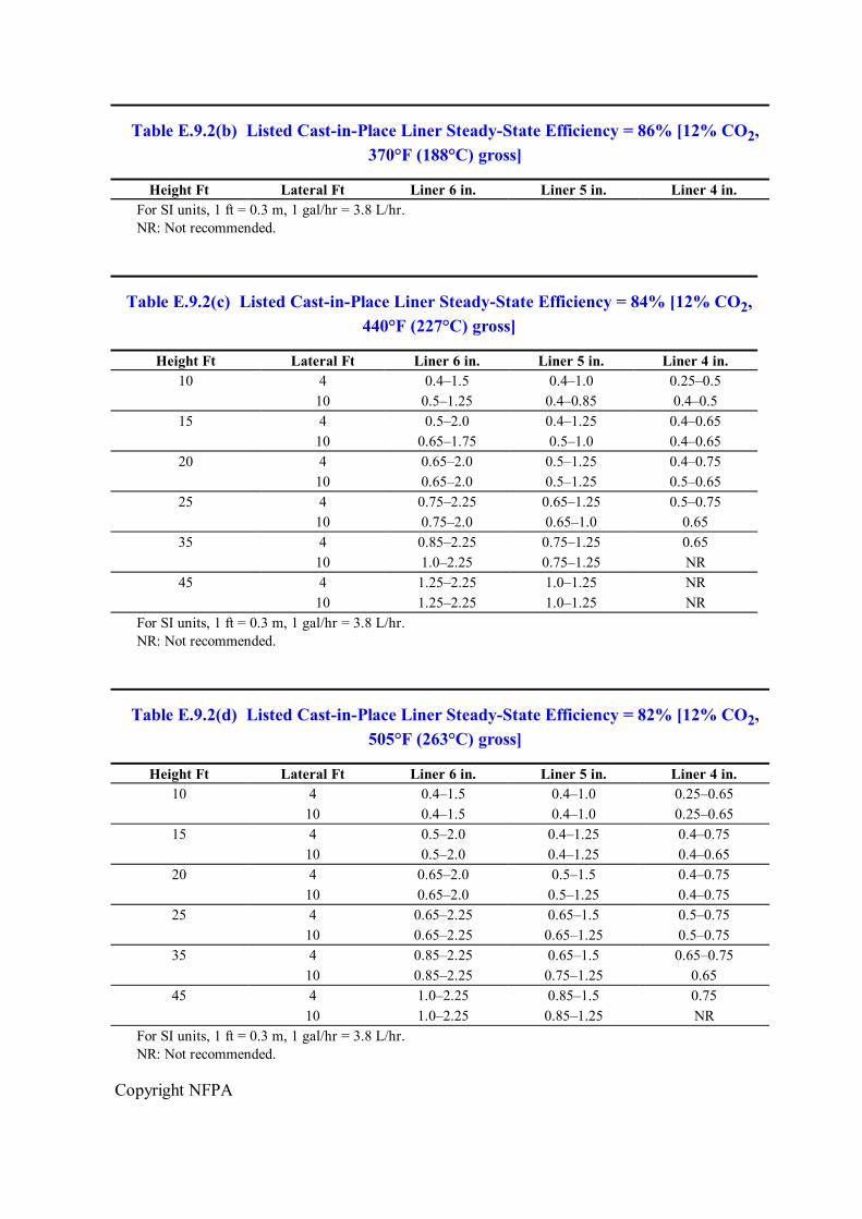
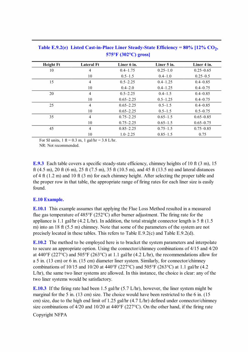
A new Appendix E, Relining Masonry Chimneys, to provide needed guidance for evaluation, repair, and relining of existing masonry chimneys when replacing heating systems with high efficiency combustion appliances
The 2001 edition of NFPA 31 included the following major changes:
A major editorial reorganization of the text to comply with the new Manual of Style for NFPA Technical Committee Documents
Recognition of nonmetallic fuel oil storage tanks for inside use
A return to the 1¼ in. vent diameter for inside fuel oil storage tanks, based on fullscale fire tests
An increase in the number of storage tanks that can be manifolded together, if the tanks are part of an engineered fuel storage system
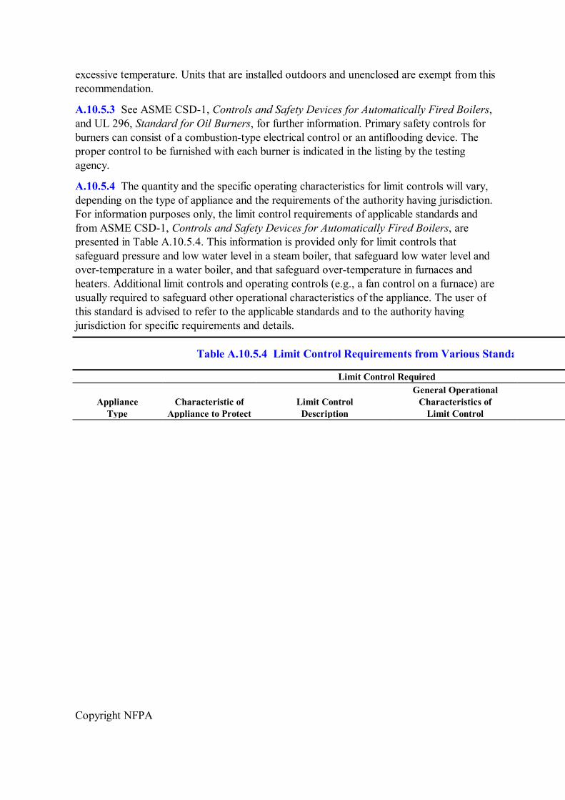
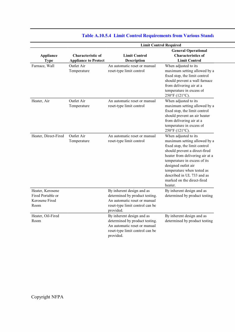
Appendix text to 10.5.4 (43.4 in the 1997 edition) that provides guidance on the appropriate types of limit controls for the various appliances
A new Chapter 12 to address appliances that can burn used oil
A new Chapter 13 to address appliances that can burn either gaseous fuels or fuel oil
Major revisions to Appendix E, Relining Masonry Chimneys
The 2006 edition incorporates the following major amendments:
Revised guidance in 6.6.7 for inspecting the chimney or flue gas venting system prior to installation of oilfired appliances. The guidance limits the scope of this inspection, but requires written notification of deficiencies to the owner of the premises.
Updated design standards and installation requirements for fuel oil storage tanks.
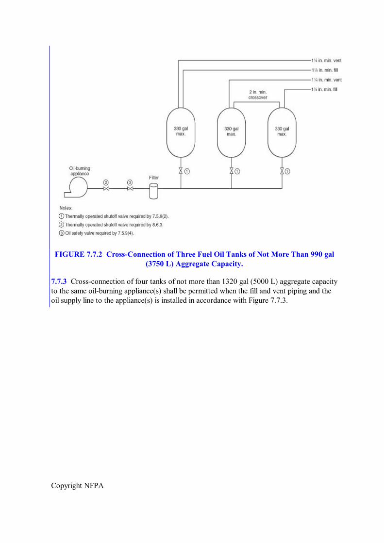
Complete revision of Section 7.5 on installation of fuel oil storage tanks in buildings. Included is replacement of previous criteria for allowable storage quantities in unenclosed and enclosed environments with simpler criteria used by NFPA 37, Standard for the Installation and Use of Stationary Combustion Engines and Gas Turbines, 2006 edition. Also included is guidance for manifolding of three and fourtank door installations.
More specific guidance in Section 7.5 for installation of oil safety valves and thermally operated shutoff valves.
Stricter requirements for taking fuel storage systems out of service, either temporarily or permanently.
More specific requirements in Section 8.9 for testing piping installations.
Copyright NFPA
Technical Committee on Liquid Fuel Burning Equipment
Allen L. Pirro, Chair Intertek Testing Services NA, Inc., NY [RT]
John E. Batey, Energy Research Center, Inc., CT [M] Rep. Oilheat Manufacturers Association
Robert V. Boltz, Vincent R. Boltz, Inc., PA [IM] Rep. National Assn. of Oil Heating Service Managers, Inc.
Aaron J. Clark, Lipton Energy Inc., MA [IM]
James R. Eddy, New England Fire Cause and Origin, Inc., NH [SE]
Jack Frederick, Frederick Geraghty Incorporated, MA [M]
Robert B. Greenes, Petroconsult Incorporated, NY [IM] Rep. Petroleum Marketers Association of America
John J. Huber, National Oilheat Research Alliance, VA [C]
Marek Kulik, FlexL International Inc., Canada [M]
George M. Kusterer, Bock Water Heaters, PA [M]
John D. Maniscalco, New York Oil Heating Association, NY [IM] Rep. New York Oil Heating Association
Michael S. Markarian, New England Fuel Institute, MA [IM]
Jay McCay, Farm & Home Oil Company, PA [IM]
Paul W. Moody, State of Maine, ME [E]
Edward J. Peznowski, Connecticut Department of Public Safety, CT [E]
John J. Pilger, Chief Chimney Services, Inc., NY [IM] Rep. National Chimney Sweep Guild
Bernard A. Smith, Concord Energy Options, MA [SE]
Charles R. Tibboles, R. W. Beckett Corporation, OH [M]
John R. Wiggins, Underwriters Laboratories Inc., NC [RT]
Copyright NFPA
Alternates
David C. Bixby, Gas Appliance Manufacturers Association, VA [M] (Voting Alt. to GAMA Rep.)
Royal Edwards, National Chimney Sweep Guild, FL [IM] (Alt. to J. J. Pilger)
Robert G. Hedden, Oilheat Associates, VT [M] (Alt. to J. E. Batey)
Dale D. Hersey, State of Maine, ME [E] (Alt. to P. W. Moody)
Roland A. Riegel, Underwriters Laboratories Inc., NY [RT] (Alt. to J. R. Wiggins)
Robert P. Benedetti, NFPA Staff Liaison
This list represents the membership at the time the Committee was balloted on the final text of this edition. Since that time, changes in the membership may have occurred. A key to classifications is found at the back of the document.
NOTE: Membership on a committee shall not in and of itself constitute an endorsement of the Association or any document developed by the committee on which the member serves.
Committee Scope: This Committee shall have primary responsibility for documents on the safeguarding against the fire, explosion, and life safety hazards associated with the installation and use of stationary and portable liquid fuelburning equipment, including: (1) related fuel storage tanks and associated piping, venting systems, pumps, and controls; (2) the combustion air supply and flue gas venting systems for the liquid fuel burning equipment; and (3) combustion and safety controls.
This Committee does not have responsibility for: (1) boilerfurnaces with fuel input ratings of 3660 kW (12,500,000 BTU per hr. or 10,000 lbs. steam per hr.) or more; (2) process ovens; (3) process furnaces; or (4) internal combustion engines.
NFPA 31 Standard for the
Installation of OilBurning Equipment 2006 Edition
IMPORTANT NOTE: This NFPA document is made available for use subject to important notices and legal disclaimers. These notices and disclaimers appear in all publications containing this document and may be found under the heading “Important Notices and Disclaimers Concerning NFPA Documents.” They can also be obtained on request from NFPA or viewed at www.nfpa.org/disclaimers.
NOTICE: An asterisk (*) following the number or letter designating a paragraph indicates
Copyright NFPA
that explanatory material on the paragraph can be found in Annex A.
Changes other than editorial are indicated by a vertical rule beside the paragraph, table, or figure in which the change occurred. These rules are included as an aid to the user in identifying changes from the previous edition. Where one or more complete paragraphs have been deleted, the deletion is indicated by a bullet (•) between the paragraphs that remain.
A reference in brackets [ ] following a section or paragraph indicates material that has been extracted from another NFPA document. As an aid to the user, the complete title and edition of the source documents for extracts in mandatory sections of the document are given in Chapter 2 and those for extracts in informational sections are given in Annex F. Editorial changes to extracted material consist of revising references to an appropriate division in this document or the inclusion of the document number with the division number when the reference is to the original document. Requests for interpretations or revisions of extracted text shall be sent to the technical committee responsible for the source document.
Information on referenced publications can be found in Chapter 2 and Annex F.
Chapter 1 Administration
1.1 Scope.
1.1.1 This standard shall apply to the installation of stationary oilburning equipment and appliances, including but not limited to industrial, commercial, and residentialtype steam, hot water, or warm air heating plants; domestictype range burners and space heaters; and portable oilburning equipment.
1.1.2 This standard shall also apply to all accessory equipment and control systems, whether electric, thermostatic, or mechanical, and all electrical wiring connected to oilfired equipment.
1.1.3 This standard shall also apply to the installation of oil storage and supply systems connected to oilfired equipment and appliances.
1.1.4 This standard shall also apply to those multifueled appliances in which fuel oil is one of the optional fuels.
1.1.5* This standard shall not apply to internal combustion engines, oil lamps, or portable devices not specifically covered in this standard. (See Chapter 11 for portable devices that are covered in this standard.)
1.2 Purpose.
The purpose of this standard is to provide minimum requirements for the safe installation of oilfired stationary equipment and appliances and all related equipment so as to prevent fires and explosions.
1.3 Application. (Reserved)
Copyright NFPA
1.4 Retroactivity.
The provisions of this standard reflect a consensus of what is necessary to provide an acceptable degree of protection from the hazards addressed in this standard at the time the standard was issued.
1.4.1 Unless otherwise specified, the provisions of this standard shall not apply to facilities, equipment, structures, or installations that existed or were approved for construction or installation prior to the effective date of the standard. Where specified, the provisions of this standard shall be retroactive.
1.4.2 In those cases where the authority having jurisdiction determines that the existing situation presents an unacceptable degree of risk, the authority having jurisdiction shall be permitted to apply retroactively any portions of this standard deemed appropriate.
1.4.3 The retroactive requirements of this standard shall be permitted to be modified if their application clearly would be impractical in the judgment of the authority having jurisdiction, and only where it is clearly evident that a reasonable degree of safety is provided.
1.5 Equivalency.
Nothing in this standard is intended to prevent the use of systems, methods, or devices of equivalent or superior quality, strength, fire resistance, effectiveness, durability, and safety over those prescribed by this standard.
1.5.1 Technical documentation shall be submitted to the authority having jurisdiction to demonstrate equivalency.
1.5.2 The system, method, or device shall be approved for the intended purpose by the authority having jurisdiction.
1.6 Units.
1.6.1 The units of measure in this standard are presented first in U.S. customary units (inch/pound units). International System (SI) of Units follow the inch/pound units in parentheses.
1.6.2 Either system of units shall be acceptable for satisfying the requirements in the standard.
1.6.3 Users of this standard shall apply one system of units consistently and shall not alternate between units.
1.6.4 The values presented for measurements in this standard are expressed with a degree of precision appropriate for practical application and enforcement. It is not intended that the application or enforcement of these values be more precise than the precision expressed.
1.6.5 Where extracted text contains values expressed in only one system of units, the values in the extracted text have been retained without conversion to preserve the values established by the responsible technical committee in the source documents.
Copyright NFPA
1.7 Code Adoption Requirements. (Reserved)
Chapter 2 Referenced Publications
2.1 General.
The documents or portions thereof listed in this chapter are referenced within this standard and shall be considered part of the requirements of this document.
2.2 NFPA Publications.
National Fire Protection Association, 1 Batterymarch Park, Quincy, MA 021697471.
NFPA 13, Standard for the Installation of Sprinkler Systems, 2002 edition.
NFPA 15, Standard for Water Spray Fixed Systems for Fire Protection, 2001 edition.
NFPA 30, Flammable and Combustible Liquids Code, 2003 edition.
NFPA 30A, Code for Motor Fuel Dispensing Facilities and Repair Garages, 2003 edition.
NFPA 54, National Fuel Gas Code, 2006 edition.
NFPA 70, National Electrical Code ® , 2005 edition.
NFPA 80, Standard for Fire Doors and Fire Windows, 1999 edition.
NFPA 85, Boiler and Combustion Systems Hazards Code, 2004 edition.
NFPA 86, Standard for Ovens and Furnaces, 2003 edition.
NFPA 90A, Standard for the Installation of AirConditioning and Ventilating Systems, 2002 edition.
NFPA 90B, Standard for the Installation of Warm Air Heating and AirConditioning Systems, 2006 edition.
NFPA 211, Standard for Chimneys, Fireplaces, Vents, and Solid Fuel–Burning Appliances, 2006 edition.
2.3 Other Publications.
2.3.1 API Publication.
American Petroleum Institute, 1220 L Street, NW, Washington, DC 20005.
API Standard 650, Specifications for Welded Steel Tanks for Oil Storage, 1998.
2.3.2 ASME Publications.
American Society of Mechanical Engineers, Three Park Avenue, New York, NY 100165990.
ANSI/ASME B36.10M, Standard on Welded and Seamless Wrought Steel Pipe, 2004.
Copyright NFPA
Boiler and Pressure Vessel Code.
2.3.3 ASTM Publications.
American Society for Testing and Materials, 100 Barr Harbor Drive, West Conshohocken, PA 194282959.
ASTM D 396, Standard Specification for Fuel Oils, 2005.
2.3.4 CAN/CGSB Publication.
Canadian General Standards Board, Place du Portage III, 6B1, 11 Laurier Street, Gatineau, QC, K1A 1G6, Canada.
CAN/CGSB 3.299(2), Heating Fuel Oil, 2004.
2.3.5 UL Publications.
Underwriters Laboratories Inc., 333 Pfingsten Road, Northbrook, IL 600622096.
UL 58, Standard for Steel Underground Tanks for Flammable and Combustible Liquids, 1996, with revisions through July 1998.
UL 80, Standard for Steel Inside Tanks for OilBurner Fuel, 1996, with revisions through June 2003.
UL 142, Standard for Steel Aboveground Tanks for Flammable and Combustible Liquids, 2002.
UL 296, Standard for Oil Burners, 2003, with revisions through January 2004.
UL 296A, Standard for Waste OilBurning AirHeating Appliances, 1995, with revisions through May 2004.
UL 443, Standard for Steel Auxiliary Tanks for Oil Burner Fuel, 1995.
UL 795, Standard for Commercial Industrial GasHeating Equipment, 1999.
UL 1316, Standard for GlassFiber Reinforced Plastic Underground Storage Tanks for Petroleum Products, 1994, with revisions through April 1996.
UL 1746, Standard for External Corrosion Protection Systems for Steel Underground Storage Tanks, 1993.
UL 2080, Standard for Fire Resistant Tanks for Flammable and Combustible Liquids, 2000.
UL 2085, Standard for Protected Aboveground Tanks for Flammable and Combustible Liquids, 1997.
UL 2244, Standard for Aboveground Flammable Liquid Tank Systems, 1999.
UL 2245, BelowGrade Vaults for Flammable Liquid Storage Tanks, 1999.
SU 2258, Outline of Investigation for Tanks for Oil Burner Fuel — NonMetallic, 1999.
2.3.6 U.S. Government Publication.
Copyright NFPA
U.S. Government Printing Office, Washington DC 20402.
Title 40, Code of Federal Regulations, Part 279.23, “OnSite Burning in Space Heaters.”
2.4 References for Extracts in Mandatory Sections.
NFPA 54, National Fuel Gas Code, 2006 edition.
NFPA 70, National Electrical Code ® , 2005 edition.
NFPA 86, Standard for Ovens and Furnaces, 2003 edition.
NFPA 97, Standard Glossary of Terms Relating to Chimneys, Vents, and HeatProducing Appliances, 2003 edition.
NFPA 211, Standard for Chimneys, Fireplaces, Vents, and Solid Fuel–Burning Appliances, 2006 edition.
NFPA 220, Standard on Types of Building Construction, 2006 edition.
NFPA 853, Standard for the Installation of Stationary Fuel Cell Power Systems, 2003 edition.
NFPA 1451, Standard for a Fire Service Vehicle Operations Training Program, 2002 edition.
Chapter 3 Definitions
3.1 General.
The definitions contained in this chapter shall apply to the terms used in this standard. Where terms are not defined in this chapter or within another chapter, they shall be defined using their ordinarily accepted meanings within the context in which they are used. MerriamWebster's Collegiate Dictionary, 11th edition, shall be the source for the ordinarily accepted meaning.
3.2 NFPA Official Definitions.
3.2.1* Approved. Acceptable to the authority having jurisdiction.
3.2.2* Authority Having Jurisdiction (AHJ). An organization, office, or individual responsible for enforcing the requirements of a code or standard, or for approving equipment, materials, an installation, or a procedure.
3.2.3 Labeled. Equipment or materials to which has been attached a label, symbol, or other identifying mark of an organization that is acceptable to the authority having jurisdiction and concerned with product evaluation, that maintains periodic inspection of production of
Copyright NFPA
labeled equipment or materials, and by whose labeling the manufacturer indicates compliance with appropriate standards or performance in a specified manner.
3.2.4* Listed. Equipment, materials, or services included in a list published by an organization that is acceptable to the authority having jurisdiction and concerned with evaluation of products or services, that maintains periodic inspection of production of listed equipment or materials or periodic evaluation of services, and whose listing states that either the equipment, material, or service meets appropriate designated standards or has been tested and found suitable for a specified purpose.
3.2.5 Shall. Indicates a mandatory requirement.
3.2.6 Should. Indicates a recommendation or that which is advised but not required.
3.2.7 Standard. A document, the main text of which contains only mandatory provisions using the word “shall” to indicate requirements and which is in a form generally suitable for mandatory reference by another standard or code or for adoption into law. Nonmandatory provisions shall be located in an appendix or annex, footnote, or fineprint note and are not to be considered a part of the requirements of a standard.
3.3 General Definitions.
3.3.1 Air Heater. An indirectfired appliance intended to supply heated air for space heating and other purposes, but not intended for permanent installation.
3.3.2 Antiflooding Device. A safety control that causes the flow of (liquid) fuel to be shut off when a rise in fuel level occurs or when excess fuel is received and that operates before the hazardous discharge of fuel can occur.
3.3.3 Appliance.
3.3.3.1 Industrial LowHeat Appliance. An industrial appliance such as a floormounted or suspendedtype warmair furnace that is larger than 100 ft 3 (2.8 m 3 ) in size, excluding blower compartment, fan compartment, and burner equipment; a steam boiler that operates at pressures that do not exceed 50 psig (gauge pressure of 345 kPa) and is larger than 100 ft 3 (2.8 m 3 ) in size, excluding burner equipment; a water boiler that operates at water temperatures of not more than the temperature of saturated steam at pressures that do not exceed 50 psig (gauge pressure of 345 kPa) and is larger than 100 ft 3 (2.8 m 3 ), excluding burner equipment; a floor mounted or suspended type unit heater larger than 100 ft 3 (2.8 m 3 ) in size, excluding blower compartment, fan compartment, and burner equipment; a commercial cooking range; a bake oven; a candy furnace; a stereotype furnace; a drying and curing appliance; or any other process appliance in which materials are heated or melted at temperatures (excluding flue gas temperature) that do not exceed 600°F (316°C).
3.3.3.2 Industrial MediumHeat Appliance. A steam boiler that operates at pressures that exceed 50 psig (gauge pressure of 345 kPa) or an industrial appliance larger than 100 ft 3 (2.8 m 3 ) in size, excluding blower compartment, fan compartment, and burner equipment, such as an annealing furnace (glass or metal), a charcoal furnace, a galvanizing furnace, a gas producer, or a commercial or industrial incinerator.
3.3.3.3 Industrial HighHeat Appliance. An industrial appliance that is larger than 100 ft 3
Copyright NFPA
(2.8 m 3 ) in size, excluding blower compartment, fan compartment, and burner equipment, such as a billet or bloom furnace, a blast furnace, a brass melter, a cupola, a glass furnace, an openhearth furnace, a ceramic kiln, or a vitreous enameling oven for ferrous materials.
3.3.4 Boiler. A closed vessel in which water is heated, steam is generated, steam is superheated, or in which any combination thereof takes place by the application of heat from combustible fuels, in a selfcontained or attached furnace.
3.3.4.1 High Pressure Boiler. A boiler for generating steam at gauge pressures in excess of 15 psi (gauge pressure of 103 kPa), or for heating water to a temperature in excess of 250°F (121°C) or at a gauge pressure in excess of 160 psi (gauge pressure of 1100 kPa).
3.3.4.2 Hot Water Supply Boiler. A lowpressure hot water boiler having a volume exceeding 120 gal (454 L), or a heat input exceeding 200,000 Btu/hr (58.6 kW), or an operating temperature exceeding 200°F (93°C) that provides hot water to be used outside the boiler.
3.3.4.3 Low Pressure Boiler. A boiler for generating steam at pressures not in excess of 15 psi (gauge pressure of 103 kPa) or for furnishing water at a maximum temperature of 250°F (121°C) at a maximum gauge pressure of 160 psi (gauge pressure of 1100 kPa).
3.3.5 Btu. Abbreviation for British thermal unit. The quantity of heat needed to raise the temperature of 1 pound of water 1°F.
3.3.6 Burner.
3.3.6.1 Automatically Ignited Burner. A burner equipped so that the main burner fuel can be turned on and ignited automatically.
3.3.6.2 Manually Ignited Burner. A burner equipped so that the main burner fuel is turned on only by hand and ignited under supervision.
3.3.6.3 Mechanical Draft–Type Burner. A burner that includes a powerdriven fan, blower, or other mechanism as the primary means for supplying the air for combustion.
3.3.6.4 Natural Draft–Type Burner. A burner that depends primarily on the natural draft created in the chimney or venting system to induce the air required for combustion into the burner.
3.3.7* Central Heating Appliance. A stationary heating appliance comprising the following: boilers, central furnaces, floor furnaces, and wall furnaces.
3.3.8 Centralized Oil Distribution System. A system of piping through which oil is supplied from a remote central supply tank or tanks to one or more buildings, mobile homes, recreational vehicles, or other structures.
3.3.9 Chimney. A structure containing one or more vertical or nearly vertical passageways for conveying flue gases to the outside atmosphere. [211, 2006]
3.3.9.1 FactoryBuilt Chimney.
3.3.9.1.1 Building Heating Appliance–Type FactoryBuilt Chimney. A heating appliance chimney suitable for continuous use at 1000°F (538°C), composed of listed, factorybuilt
Copyright NFPA
components, designed for open, nonenclosed use at specified minimum clearances to combustibles, and assembled in accordance with the terms of its listing to form the completed chimney. [97, 2003]
3.3.9.1.2 MediumHeat Appliance–Type FactoryBuilt Chimney. A chimney used with appliances that produce maximum flue gas temperatures of 1800°F (982°C), composed of listed, factorybuilt components, suitable for open, nonenclosed use at specified minimum clearances to combustibles, and assembled in accordance with the terms of the listing to form the completed chimney. [211, 2006]
3.3.9.1.3 ResidentialType and Building Heating Appliance–Type FactoryBuilt Chimney. A chimney suitable for continuous use at 1000°F (538°C), composed of listed, factorybuilt components that might be fully enclosed in combustible, residentialtype construction, and that is assembled in accordance with the terms of the listing to form the completed chimney.
3.3.9.1.4 Unlisted Metal (Smokestack) Chimney. A manufactured or fieldconstructed chimney intended only for nonresidential applications, having one or more metal walls or made of metal with a refractory lining, that is capable of withstanding the flue gas conditions of its use. [211, 2006]
3.3.9.2 Masonry Chimney. A fieldconstructed chimney of solid masonry units, bricks, stones, listed masonry chimney units, or reinforced portland cement concrete that is lined with suitable chimney flue liners and built in accordance with the provisions of Chapter 4 of NFPA 211, Standard for Chimneys, Fireplaces, Vents, and Solid Fuel–Burning Appliances. [211, 2006]
3.3.10 Chimney Connector. The pipe that connects a fuelburning appliance to a chimney. [211, 2006]
3.3.11 Chimney Flue. The passage in a chimney for conveying the flue gases to the outside atmosphere. [211, 2006]
3.3.12 Clearance. The distance between a heatproducing appliance, chimney, chimney connector, vent, vent connector, or plenum and other surfaces.
3.3.13 Combustible Material. Any material that will burn, regardless of its autoignition temperature. [220, 2006]
3.3.14 Confined Space. For the purposes of this standard, a space whose volume is less than 50 ft 3 per 1000 Btu/hr (4.8 m 3 per kW) of the aggregate input rating of all appliances installed in that space.
3.3.15 ConstantLevel Valve. A device for maintaining a constant level of oil fuel within a reservoir for delivery to an oil burner.
3.3.16 Control.
3.3.16.1 Limit Control. An automatic safety control that responds to changes in fluid flow, fluid level, pressure, or temperature, which is normally set beyond the operating range to
Copyright NFPA
limit the operation of the controlled equipment by shutting off the energy supply.
3.3.16.2 Primary Safety (Combustion Safeguard) Control. A safety control that responds directly to flame properties, senses the presence or absence of flame, and, in the event of ignition failure or unintentional flame extinguishment, causes safety shutdown.
3.3.16.3 Safety Control. Automatic controls (including relays, switches, and other auxiliary equipment used in conjunction to form a safety control system) that are intended to prevent unsafe operation of the controlled equipment.
3.3.17 Cooking Appliance, FloorMounted RestaurantType. A range, oven, broiler, or other miscellaneous cooking appliance, designated for use in hotel and restaurant kitchens and for mounting on the floor. [211, 2006]
3.3.18 Damper. A valve or plate for controlling draft or the flow of gases, including air. [853, 2003]
3.3.19 Dew Point. As applied to the combustion products produced by oilburning appliances, the temperature below which components of the combustion products will condense on exposed surfaces.
3.3.19.1 Acid Dew Point. The temperature below which sulfuric acid in the combustion products will condense on exposed surfaces.
3.3.19.2 Water Dew Point. The temperature below which water in the combustion products will condense on exposed surfaces.
3.3.20 DirectFired Appliance. A fuelburning appliance in which the products of combustion (flue gases) are mixed with the medium (e.g., air) being heated.
3.3.21 Direct Vent Appliance (Direct Vent System, Sealed Combustion System Appliance). A system consisting of an appliance, combustion air and flue gas connections between the appliance and the outside atmosphere, and a vent cap supplied by the manufacturer, constructed so that all air for combustion and draft control is obtained from the outside atmosphere and all flue gases are discharged to the outside atmosphere.
3.3.22 Direct Vent System. See 3.3.21, Direct Vent Appliance.
3.3.23 Direct Venting System. A venting system that is constructed and installed so that air for combustion and draft control is taken from interior building spaces and all combustion products are discharged to the outside atmosphere.
3.3.24 Draft. A pressure difference that causes gases or air to flow through a chimney, vent, flue, or fuelburning equipment. [54, 2006]
3.3.24.1* Mechanical Draft. Draft produced by mechanical means.
3.3.24.2 Natural Draft. Draft produced by the difference in the weight of a column of flue gases within a chimney or vent system and a corresponding column of air of equal dimension outside the chimney or venting system.
3.3.25 Draft Fan. A mechanical means used with a chimney venting system to augment the
Copyright NFPA
natural draft developed in the connected chimney.
3.3.26 Draft Regulator (Barometric). A device built into a fuel burning appliance or made a part of a chimney connector or vent connector that functions to maintain draft through an appliance to a desired value by admitting ambient air into the appliance chimney, chimney connector, vent, or vent connector.
3.3.27 Flue Collar. That portion of an appliance designed for attachment of a chimney or vent connector or a draft hood. [211, 2006]
3.3.28* Fuel Oil. For the purposes of this standard, any hydrocarbon oil as specified by ASTM D 396, Standard Specification for Fuel Oils, or CAN/CGSB 3.299(2), Heating Fuel Oil, and having a minimum flash point of 100°F (38°C).
3.3.29 Furnace.
3.3.29.1 Central WarmAir Furnace. A selfcontained indirectfired or electrically heated appliance designed to supply heated air through ducts to spaces remote from or adjacent to the appliance location. [211, 2006]
3.3.29.2 Duct Furnace. A central furnace designed for installation in a duct of an air distribution system to supply warm air for heating that depends for air circulation on a blower not furnished as part of the furnace.
3.3.29.3* Floor Furnace. A selfcontained indirectfired or electrically heated furnace designed to be suspended from the floor of the space to be heated. [211, 2006]
3.3.29.4 ForcedAirType Central Furnace. A central furnace equipped with a blower that provides the primary means for the circulation of air.
3.3.29.4.1 ForcedAirType Central, AtticType Furnace. A forcedairtype furnace designed specifically for installation in an attic or in a space with low headroom that is normally occupied.
3.3.29.4.2 ForcedAirType Central, DownflowType Furnace. A forcedairtype furnace designed with airflow essentially in a vertical path, discharging air at or near the bottom of the furnace.
3.3.29.4.3 ForcedAirType Central, HorizontalType Furnace. A forcedairtype furnace designed with airflow through the furnace essentially in a horizontal path.
3.3.29.4.4 ForcedAirType Central, UpflowType Furnace. A forcedairtype furnace designed with airflow essentially in a vertical path, discharging air at or near the top of the furnace.
3.3.29.5 GravityType Central Furnace. A central furnace depending primarily on circulation of air by gravity. [97, 2003]
3.3.29.6 GravityType Central, with Booster Fan Furnace. A central furnace equipped with a booster fan that does not materially restrict free circulation of air by gravity flow when such a fan is not in operation. [97, 2003]
Copyright NFPA
3.3.29.7 GravityType Central, with Integral Fan Furnace. A central furnace equipped with a fan as an integral part of its construction and operable on gravity systems only where the fan is used only to overcome the internal resistance to airflow. [97, 2003]
3.3.29.8 Stationary Industrial Furnace. A low, medium, or highheat appliance classified in accordance with its character and size and the temperatures developed in the portions thereof where substances or materials are heated for baking, drying, roasting, melting, vaporizing, or other purposes.
3.3.30 Heat Reclaimer, Chimney Connector–Type. A heat exchanger intended to be installed in a chimney connector between a heating appliance and the chimney to transfer heat from the flue gases through metal to air or water. [211, 2006]
3.3.31* Heating and Cooking Appliance. An oilfired appliance not intended for central heating.
3.3.32 Ignition Zone. The location on the burner where ignition and combustion of the main burner fuel occurs.
3.3.33 IndirectFired Appliance. A fuelburning appliance in which products of combustion (flue gases) are not mixed in the appliance with the medium (e.g., air) being heated.
3.3.34 Installation. The complete settinginplace and readying for operation of an oilburning appliance and its accessories and equipment.
3.3.35 KeroseneFired Portable Heater. An unvented, selfcontained, selfsupporting heater, with integral reservoir, designed to be carried from one location to another.
3.3.36 Kerosene Stove. An unvented, selfcontained, selfsupporting keroseneburning range or room heater equipped with an integral fuel tank not exceeding a 2gal (7.6L) capacity.
3.3.37 Main Burner. A device or group of devices essentially forming an integral unit for the final conveyance of fuel or a mixture of fuel and air to the combustion zone and on which combustion takes place to accomplish the function for which the appliance is designed.
3.3.38 Main Burner Flame Establishing Period. The length of time fuel is permitted to be delivered to the main burner before the flamesensing device is required to detect the main burner flame.
3.3.39 MultipleFueled Appliance. An appliance that is designed and intended to burn either solid, liquid, or gaseous fuels, or a combination of these.
3.3.40* Oil Burner. A device for burning oil in heating appliances such as boilers, furnaces, water heaters, and ranges.
3.3.41* OilBurning Appliance (OilBurning Unit). An appliance equipped with one or more oil burners and all the necessary safety controls, electrical equipment, and related equipment manufactured for assembly as a complete unit.
3.3.42 OilBurning Equipment. An oil burner of any type, together with its tank, piping, wiring, controls, and related devices, including all oil burners, oilfired appliances, and
Copyright NFPA
heating and cooking appliances, but excluding those exempted by 1.1.5.
3.3.43* OilBurning Stove. A selfcontained, freestanding, abovethefloor, indirectfired appliance equipped with one or more oil burners.
3.3.44 OilGasFired Appliance. An appliance that is capable of burning fuel oils and fuel gases as a main fuel source in an alternate manner.
3.3.45 Pilot. A flame that is used to light the main burner. [86, 2003]
3.3.46 Pilot Flame Establishing Period. For the purposes of this standard, the length of time fuel is permitted to be delivered to a proved pilot before the flamesensing device is required to detect the pilot flame.
3.3.47 Power Venting. The application of a mechanical means of removing combustion products to the outside atmosphere. (See 3.3.24.1, Mechanical Draft.)
3.3.48 PrePurge Period. The interval of time during burner startup in which air is introduced into the combustion chamber and the associated flue passages in such volume and manner as to completely replace the air or fuelair mixture contained therein prior to initiating ignition.
3.3.49 Qualified Person. A person who, by possession of a recognized degree, certificate, professional standing, or skill, and who, by knowledge, training, and experience, has demonstrated the ability to deal with problems relating to a particular subject matter, work, or project. [1451, 2002]
3.3.50 Range. An appliance intended primarily for cooking, including roasting, baking, or broiling, or any combination of these functions.
3.3.51 Readily Accessible. Capable of being reached quickly for operation, renewal, or inspections, without requiring those to whom ready access is required to climb over or remove obstacles or to resort to portable ladders. [70, 2005]
3.3.52 Room Heater. A heating appliance intended for installation in the space being heated and not intended for duct connection. [211, 2006]
3.3.52.1* Circulating Room Heater. A room heater with an outer jacket surrounding the heat exchanger, arranged with openings at top and bottom so that air circulates between the heat exchanger and the outer jacket. [211, 2006]
3.3.52.2 Radiant Room Heater. A room heater designed to transfer heat primarily by direct radiation. [211, 2006]
3.3.52.3 Solid Fuel Room Heater. A chimneyconnected, solid fuelburning room heater that is designed to be operated with the fire chamber closed. [211, 2006]
3.3.52.4 Combination Room Heater/Fireplace Stove. A chimneyconnected, solid fuelburning room heater that is designed to be operated with the fire chamber either open or closed.
3.3.53 Safety Shutdown. The action of shutting off all fuel and ignition energy to an appliance by means of a safety control or controls, such that restart of the appliance cannot
Copyright NFPA
be accomplished without some form of manual reset that requires local, manual intervention.
3.3.54 Sealed Combustion Venting System. See 3.3.21, Direct Vent Appliance.
3.3.55 Sidewall or ThroughWall Venting. A mechanical means applied to a nearly horizontal venting system to remove combustion products without benefit of a chimney or significant natural draft.
3.3.56 Tank.
3.3.56.1* Oil Burner Auxiliary Tank. A tank having a capacity of not more than 60 gal (227 L) that is listed for installation in the supply piping between a burner and its main fuel supply tank. (See 3.3.56.3, Oil Burner Integral Tank.)
3.3.56.2 Oil Burner Gravity Tank. A supply tank from which the oil is delivered directly to the burner by gravity.
3.3.56.3 Oil Burner Integral Tank. A tank that is furnished by the manufacturer as an integral part of an oilburning appliance. (See 3.3.56.1, Oil Burner Auxiliary Tank.)
3.3.56.4 Oil Burner Storage Tank. A separate tank that is not connected directly to the oilburning appliance.
3.3.56.5 Oil Burner Supply Tank. A separate tank connected either directly or by means of a pump to the oilburning appliance.
3.3.57 Total Input Rating. The sum of the maximum Btu rating, as marked on the appliance by the manufacturer, of all appliances, not the nozzle sizes or actual firing rates.
3.3.58 Trial for Ignition Period. The interval of time during which main burner fuel is permitted to be delivered into the ignition zone before the flamesensing device is required to detect flame. (See 3.3.38, Main Burner Flame Establishing Period, and 3.3.46, Pilot Flame Establishing Period.)
3.3.59* Unconfined Space. Any space whose volume is equal to or greater than 50 ft 3 per 1000 Btu/hr (4.8 m 3 per kW) of the aggregate input rating of all fuelburning appliances installed therein.
3.3.60* Unit Heater. A selfcontained heating appliance that might or might not include an integral fan for circulating air, that can be of the floormounted or suspended type and that is intended for the heating of the space in which it is installed.
3.3.61 Used Oil. Oil that consists of primarily used automotive crankcase oil from internal combustion engines, including, but not limited to, used engine oils, used automotive transmission fluids, used gear lubricants, machining oils, used hydraulic fluids, or any mixture thereof and that can vary considerably in its chemical and physical properties.
3.3.62 Valve.
3.3.62.1 Manual Oil Shutoff Valve. A manually operated valve in an oil line for the purpose of turning on or completely shutting off the oil supply to the burner.
3.3.62.2 Metering (Regulating) Valve. An oil control valve for regulating burner input.
Copyright NFPA
3.3.62.3 Oil Control Valve. An automatically or manually operated device consisting essentially of an oil valve for controlling the fuel supply to a burner.
3.3.62.4 Safety Valve. An automatic oil control valve of the “on” and “off” type (without any bypass to the burner) that is actuated by a safety control or by an emergency device.
3.3.63 Vent, Type L. A vertical or nearly vertical passageway composed of listed factorybuilt components assembled in accordance with the terms of listing for conveying flue gases from oil and gas appliances or their vent connectors to the outside atmosphere.
3.3.64* Venting System (Flue Gases). A continuous, open passageway from the flue collar or draft hood of a fuelburning appliance to the outside atmosphere for the purpose of removing flue gases. [211, 2006]
3.3.65* Wall Furnace. A selfcontained vented appliance, complete with grilles or equivalent, designed for incorporation in or permanent attachment to the structure of a building, manufactured home, or recreational vehicle and furnishing heated air directly into the space to be heated through openings in the casing.
3.3.65.1 FanType Wall Furnace. A wall furnace equipped with a fan for the circulation of air. [211, 2006]
3.3.65.2 GravityType Wall Furnace. A wall furnace dependent on the circulation of air by gravity. [211, 2006]
3.3.66 Water Heater. A fuelburning appliance for heating water to a temperature not more than 200°F (93°C). [211, 2006]
Chapter 4 Basic Installation and Operation Requirements
4.1 Scope.
This chapter shall apply to the basic installation and operation requirements for oilburning appliances and equipment.
4.2 Use of Approved Equipment.
4.2.1 Oilburning appliances and equipment shall be approved.
4.2.2 Appliances and equipment listed for a specific purpose shall be considered as meeting the requirements of this standard.
4.3 Installation of OilBurning Appliances and Equipment.
4.3.1 Before installing or remodeling any oilburning appliance or equipment for commercial or industrial application, plans or sketches that show the relative location of burners, tanks, pumps, piping, and elevations of buildings and their lowest floors or pits relating to the proposed installation or alteration shall be submitted to the authority having jurisdiction.
4.3.2 The installation shall be made in accordance with manufacturers' instructions, as well
Copyright NFPA
as in accordance with all federal, state, and local rules and regulations.
4.3.2.1 Such instructions shall include directions and information for attaining proper and safe installation, maintenance, and use of the appliance or equipment.
4.3.2.2 The instructions shall be left with the owner.
4.3.2.3 If for any reason it becomes necessary to change, modify, or alter a manufacturer's instructions in any way, written approval shall be obtained from the manufacturer before doing so.
4.3.3 The installation shall be made by qualified, competent technicians experienced in making such installations.
4.3.4 The installation shall be accessible for cleaning heating surfaces; for removing burners; for replacing motors, controls, air filters, chimney connectors, draft regulators, and other working parts; and for adjusting, cleaning, and lubricating parts requiring such attention.
4.3.5 Oilburning appliances shall not be installed or located in areas where combustible dusts or flammable liquids, gases, or vapors are normally present.
4.3.5.1 Return air for warm air units shall not be taken from such areas.
4.3.6 Oilburning appliances and equipment shall be installed so that a minimum 3 ft (0.9 m) separation is maintained from any electrical panelboard and a minimum 5 ft (1.5 m) separation is maintained from any unenclosed fuel oil tank.
4.3.7 After installation, the appliance or equipment shall be tested for proper operation and combustion performance to make certain that the burner is operating in a safe and acceptable manner and that all accessory equipment, controls, and safety devices function as intended.
4.3.8 Contractors installing industrial oilburning systems shall furnish diagrams showing the main oil lines and control valves, one of which shall be posted at the equipment and another at some point that will be readily accessible in case of emergency.
4.3.9 After completing the installation, the installer shall instruct the owner or operator on the proper operation of the equipment.
4.3.9.1 The installer also shall furnish the owner or operator with name(s) and telephone numbers of person(s) to contact for technical information or assistance and for routine or emergency services.
4.4 Electrical Services.
4.4.1 Electrical wiring and utilization equipment used in connection with oilburning appliances or equipment shall be installed in accordance with NFPA 70, National Electrical Code.
4.4.2 Safety control circuits shall be 2wire, 1 side grounded, with a nominal voltage not exceeding 150 volts.
4.4.3 Safety controls or protective devices shall be connected so that they interrupt the ungrounded conductor and shut all fuel flow to the appliance, including fuel flow to any pilot
Copyright NFPA
flame or burner.
4.4.4 The control circuit shall be connected to a power supply branch circuit fused at not more than the value appropriate for the rating of any control or device included in the circuit.
4.5 Acceptable Fuels.
4.5.1 The grade of fuel oil used in an oil burner shall be that for which the burner is approved and as stipulated by the manufacturer. Oil containing gasoline shall not be used as fuel. (For use of oil fuels other than those described in this paragraph, see Chapters 11, 12, and 13.)
4.5.2 Crankcase oil or used oil shall not be used as fuel unless all of the following conditions are met:
(1) The installation is in a commercial or industrial occupancy.
(2) The oilburning appliance is designed to burn crankcase oil or used oil and is listed for such use.
(3) The appliance is installed in accordance with the manufacturer's instructions and with the terms of its listing.
(4) The installation meets the applicable requirements of Section 4.6 and Chapter 12.
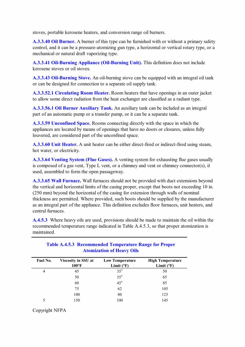
4.5.3* Where heavy oils are used, the following shall be required:
(1) The oilburning appliance shall be designed to burn such fuels.
(2) Means shall be provided to maintain the oil at its proper atomizing temperature.
(3) Automatically operated burners that require preheating of oil shall be arranged so that no oil can be delivered for combustion until the oil is at the proper atomizing temperature.
(4)* Use of an oilfired appliance that is listed in accordance with UL 296A, Standard for Waste OilBurning AirHeating Appliances, shall be deemed as meeting the intent of 4.5.3(1) through 4.5.3(3).
4.5.4 A properly sized and rated oil filter or strainer shall be installed in the oil supply line to an oil burner.
4.6 Use of Crankcase Oil and Used Oil.
4.6.1* When storing, handling, or burning crankcase oil and used oils, care shall be taken to not mix gasoline with the crankcase oil or used oil.
4.6.2 When a mixture could have a flash point below 100°F (38°C) or when a mixture could be heated above its flash point, attention shall be given to electrical installations in areas where flammable vapors or gases can be present in the atmosphere.
4.6.3 Where a supply tank is used, provisions shall be made to prevent stratification of fuel in the tank.
Copyright NFPA
4.6.4* Areas where oil leakage can occur, such as at pumps, heaters, strainers, and burners, or where maintenance is performed shall be provided with adequate ventilation. Confined fuelhandling areas and burner sites shall also be provided with adequate ventilation. Mechanical ventilation shall be provided where necessary.
4.6.5 Means shall be provided to safely dispose of spills.
4.7 Temporary Heating.
Where salamanders, space heaters, or other heating appliances are used for temporary heating, all requirements of this standard, including those for maximum operating temperatures, clearances to combustible materials, venting of combustion gases, fuel storage, safety, shutoffs, combustion and ventilation air, and electrical wiring, where applicable, shall be met and all such equipment shall be used in accordance with its listing.
Chapter 5 Air for Combustion and Ventilation
5.1 Scope.
This chapter shall apply to those requirements necessary to ensure that adequate air for safe combustion is provided for oilburning appliances and equipment.
5.2 Basic Requirements.
5.2.1 Oilburning appliances and equipment shall be installed in locations where available ventilation permits satisfactory combustion of oil, proper venting of combustion gases, and maintenance of safe ambient temperatures under normal conditions of use.
5.2.2 Appliances shall be located so that they do not interfere with the supply of air within the space.
5.2.3 Where buildings are so tight that normal infiltration does not provide sufficient air for combustion, outside air shall be introduced.
5.2.3.1 Ducts used to convey air from outdoors shall have the same crosssectional area as the free area of the openings to which they connect.
5.2.3.2 The smaller dimension of rectangular air ducts shall not be less than 3 in. (75 mm).
5.2.4 For residential and similar installations, the requirements of 5.2.1 shall be permitted to be met by application of either one of the methods covered in Section 5.3 or Section 5.4. For commercial and industrial installations, the requirements of Section 5.5 shall apply.
5.3* Appliances Located in Unconfined Spaces.
5.3.1 In unconfined spaces in buildings of conventional frame, brick, or stone construction, air for combustion and ventilation shall be permitted to be supplied by normal infiltration.
5.3.2 If normal infiltration is not sufficient because of tight construction, air for combustion and ventilation shall be obtained directly from outdoors or from spaces that freely
Copyright NFPA
communicate with outdoors by means of a permanent opening or openings having a total free area of not less than 1 in. 2 per 5000 Btu/hr (28 in. 2 per gal/hr) (4.4 cm 2 /kW), based on the total input rating of all appliances in the space.
5.4 Appliances Located in Confined Spaces.
For appliances installed in confined spaces, air for combustion and ventilation shall be provided using one of the methods set forth in this section.
5.4.1 All Air Taken from Inside the Building.
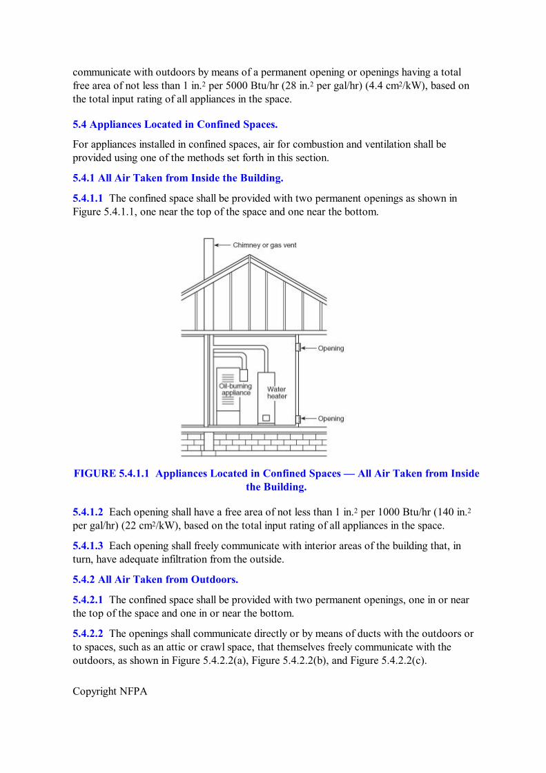
5.4.1.1 The confined space shall be provided with two permanent openings as shown in Figure 5.4.1.1, one near the top of the space and one near the bottom.
FIGURE 5.4.1.1 Appliances Located in Confined Spaces — All Air Taken from Inside the Building.
5.4.1.2 Each opening shall have a free area of not less than 1 in. 2 per 1000 Btu/hr (140 in. 2 per gal/hr) (22 cm 2 /kW), based on the total input rating of all appliances in the space.
5.4.1.3 Each opening shall freely communicate with interior areas of the building that, in turn, have adequate infiltration from the outside.
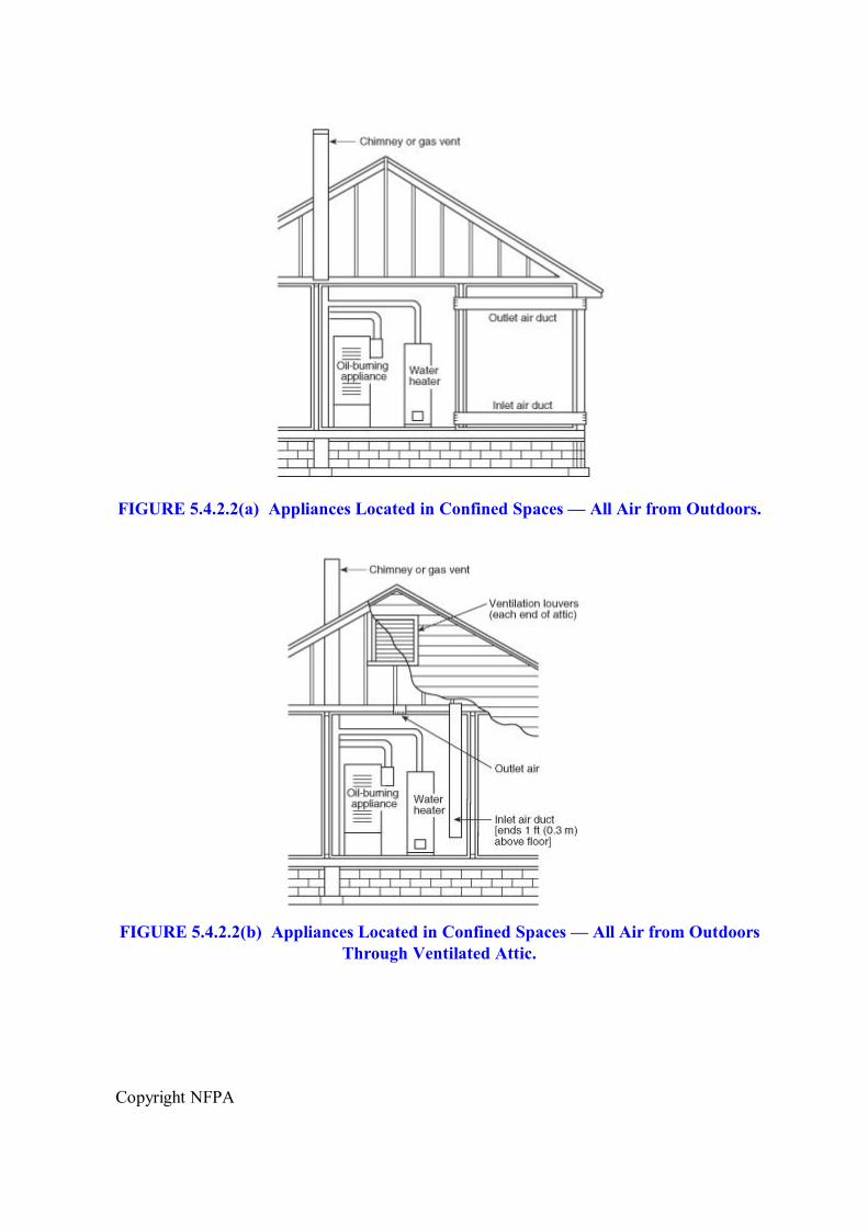
5.4.2 All Air Taken from Outdoors.
5.4.2.1 The confined space shall be provided with two permanent openings, one in or near the top of the space and one in or near the bottom.
5.4.2.2 The openings shall communicate directly or by means of ducts with the outdoors or to spaces, such as an attic or crawl space, that themselves freely communicate with the outdoors, as shown in Figure 5.4.2.2(a), Figure 5.4.2.2(b), and Figure 5.4.2.2(c).
Copyright NFPA
FIGURE 5.4.2.2(a) Appliances Located in Confined Spaces — All Air from Outdoors.
FIGURE 5.4.2.2(b) Appliances Located in Confined Spaces — All Air from Outdoors Through Ventilated Attic.
Copyright NFPA
FIGURE 5.4.2.2(c) Appliances Located in Confined Spaces — All Air from Outdoors, with Inlet Air from Ventilated Crawl Space and Outlet Air to Ventilated Attic.
5.4.2.3 Where communicating with outdoors directly or by means of vertical ducts, each opening shall have a free area of not less than 1 in. 2 per 4000 Btu/hr (35 in. 2 per gal/hr) (5.5 cm 2 /kW), based on the total input rating of all appliances in the space.
5.4.2.4 Where communicating with outdoors by means of horizontal ducts, each opening shall have a free area of not less than 1 in. 2 per 2000 Btu/hr (70 in. 2 per gal/hr) (11 cm 2 /kW), based on the total input rating of all appliances in the space.
5.4.3 Ventilation Air Taken from Inside the Building — Combustion Air Taken from Outdoors.
5.4.3.1 The confined space shall be provided with two openings for ventilation, located and sized as specified in 5.4.1 and as shown in Figure 5.4.3.1.
Copyright NFPA
FIGURE 5.4.3.1 Appliances Located in Confined Spaces, with Ventilation Air from Inside Building and Combustion Air from Outside, Ventilated Attic, or Ventilated
Crawl Space.
5.4.3.2 In addition, there shall be one opening communicating directly with the outdoors or to spaces, such as an attic or crawl space, that freely communicate with the outdoors and has a free area of not less than 1 in. 2 per 5000 Btu/hr (28 in. 2 per gal/hr) (4.4 cm 2 /kW), based on the total input of all appliances in the space.
5.5 Combustion Air for Commercial and Industrial Installations.
For commercial and industrial oilburning equipment, permanent means for supplying an ample amount of outside air shall be provided in accordance with this section.
5.5.1 For furnace or boiler rooms adjacent to outside walls and where combustion air is provided by natural ventilation from the outside, there shall be a permanent air supply inlet having a total free area of not less than 1 in. 2 per 4000 Btu/hr (35 in. 2 per gal/hr) (5.5 cm 2 / kW), based on the total input rating of the burner or burners, but in no case less than 35 in. 2 (0.425 m 2 ).
5.5.2 For furnace or boiler rooms that are not adjacent to outside walls, the combustion air shall be supplied in a manner acceptable to the authority having jurisdiction.
Copyright NFPA
5.6 Louvers and Grilles.
5.6.1 In calculating the free area required by Sections 5.2, 5.3, 5.4, and 5.5, the blocking effect of louvers, grilles, or screens protecting openings shall be taken into consideration.
5.6.2 Screens used in louvers or grilles shall not be smaller than ¼ in. (6.3 mm) mesh and shall be accessible for cleaning.
5.6.3 If the free area through a particular design of louver or grille is known, it shall be used in calculating the size of the opening needed to provide the free area required. If the free area of the design is not known, it shall be assumed that wood louvers will have 20 percent to 25 percent free area and metal louvers and grilles will have 60 percent to 75 percent free area.
5.7 Special Conditions.
Where an appliance is installed in a location where the operation of exhaust fans, kitchen ventilation systems, clothes dryers, or fireplaces can create conditions of unsatisfactory combustion or venting, special provisions shall be made subject to the approval of the authority having jurisdiction.
5.8* Specially Engineered Installations.
The size of combustion air openings required by Sections 5.3, 5.4, and 5.5 shall not govern when special engineering methods approved by the authority having jurisdiction ensure an adequate supply of air for combustion and ventilation.
Chapter 6 Venting of Combustion (Flue) Gases
6.1 Scope.
This chapter shall apply to those requirements necessary to ensure the safe venting of combustion and flue gases from oilburning appliances and equipment.
6.2 Basic Requirements.
6.2.1 Oilburning appliances and equipment other than directfired heaters, listed kerosene stoves, and listed portable kerosene heaters shall be connected to venting systems and chimneys to remove combustion (flue) gases from the combustion chamber of the appliance or equipment and to direct them to a point outside the building, as required by this chapter.
Exception: As provided for in Section 6.7.
6.2.2 The installation of oilburning appliances and equipment shall require careful consideration of positive and negative pressures in the venting system and chimney and the formation of corrosive condensate throughout the system.
6.2.3 The venting system and chimney shall be designed, constructed, and maintained to ensure that a positive flow is developed and that this flow is sufficient to remove products of combustion to the outside atmosphere.
Copyright NFPA
6.3 Draft.
6.3.1* A chimney shall be capable of producing the minimum draft recommended by the manufacturer of the appliance.
6.3.2 A draft fan, installed so that the fuel supply to the main burner is immediately shut off if the draft fan fails, shall be permitted to be used to increase low draft.
6.3.3 Two or more oilburning appliances shall be permitted to be connected to a single chimney, provided that sufficient draft is available for safe combustion in each appliance and that all products of combustion are safely removed to the outdoors.
6.3.4* Where chimney downdraft conditions cause faulty operation that creates a hazard, corrective steps shall be taken.
6.4 Draft Regulators.
6.4.1 A draft regulator shall be provided for each oilburning appliance that is connected to a chimney or power venting system unless the appliance design, conditions of installation, or combinations thereof preclude excessive chimney draft, or the appliance is listed for use without one.
6.4.2 A manually operated damper shall not be placed in the chimney connector from an oilburning appliance.
Exception: Where two or more oilburning appliances are connected to a common chimney, manual isolating dampers shall be permitted and shall be interlocked to prevent burner operation unless the damper is in the fullopen position.
6.4.3 Automatically operated dampers shall be of an approved type, shall be designed to maintain a safe damper opening at all times, and shall be arranged to prevent starting of the burner unless the damper is fully opened.
6.4.4 Fixed baffles shall be permitted to be installed in the appliance flue collar where they are specified by the appliance manufacturer.
6.4.4.1 Baffles shall be securely fastened into position. When in a closed position baffles shall not block off more than 80 percent of the chimney connector area.
6.5 Chimney Connectors.
6.5.1 An oilburning appliance shall be placed so that the chimney connector is as short as practicable.
6.5.1.1 For naturaldraft appliances, the horizontal length of a chimney connector shall not exceed 10 ft (3 m) unless a draft fan is used.
6.5.1.2 For appliances requiring a negative chimney draft, the chimney connector shall be not longer than 75 percent of the portion of the chimney above the chimneyconnector inlet.
6.5.2 A chimney connector shall not pass through a floor or ceiling.
6.5.3 A chimney connector of a low, medium, or highheat industrial appliance shall not
Copyright NFPA
pass through a combustible wall or partition.
6.5.4 Chimney connectors of appliances other than industrial appliances shall not pass through combustible walls or partitions unless the installation complies with 6.5.4.1, 6.5.4.2, or 6.5.4.3.
6.5.4.1 Chimney connectors shall be permitted to pass through a combustible wall or partition if guarded at the point of passage by one of the following:
(1) Metal ventilated thimbles not less than 12 in. (300 mm) larger in diameter than the diameter of the connector
(2) Metal or burned fireclay thimbles built in brickwork or other approved fireproofing materials and extending not less than 8 in. (200 mm) beyond all sides of the thimble
6.5.4.2 Chimney connectors shall be permitted to pass through a combustible wall or partition if all combustible material in the wall or partition is cut away from the chimney connector a sufficient distance to provide the clearance required from the connector and noncombustible insulating material is used to close up the opening.
6.5.4.3 Chimney connectors shall be permitted to pass through a combustible wall or partition if a listed, commercially available or factorybuilt vent assembly, such as a Type L vent, that is approved for use with oilfired appliances is used.
6.5.5 In masonry chimneys, the chimney connector shall extend through the chimney wall to the inner face or liner, but not beyond, and shall be firmly cemented in place.
6.5.5.1 A thimble shall be permitted to be used to facilitate removal of the chimney connector for cleaning, in which case the thimble shall be permanently cemented in place with hightemperature cement.
6.5.6 The chimney connector shall be sized in accordance with one of the following methods:
(1) The connector shall be sized using approved engineering methods, and the connected appliance shall be marked to indicate the maximum firing rate that can be used with the venting system.
(2) The connector shall be sized in accordance with the manufacturer's instructions.
6.5.7 The connector, for its entire length, shall not be smaller in effective crosssectional area than the flue collar of the appliance, as delivered or as modified in accordance with the manufacturer's instructions.
6.5.8 The chimney connector shall be of steel, refractory masonry, or corrosionresistant material and shall be maintained in good condition.
6.5.9 Where insulation of the chimney connector is required to maintain the temperature of the combustion products, an insulated Type L chimney connector shall be used.
6.5.10 The chimney connector shall maintain a pitch or rise of at least ¼ in./ft (20 mm/m) of horizontal length of pipe from the appliance to the chimney.
Copyright NFPA
6.5.11 The chimney connector shall be installed to minimize the number of elbows and to avoid sharp turns or other construction features that might create excessive resistance to the flow of flue gases.
6.5.12 Any device that will obstruct the free flow of gases shall not be installed in a chimney connector or chimney.
Exception: This shall not be construed as prohibiting the use of devices specifically listed for installation in a chimney connector, such as heat reclaimers, automatic dampers, or safety controls.
6.5.13 The chimney connector shall be securely supported.
6.5.14 Each joint of the chimney connector shall be fastened together with at least three screws.
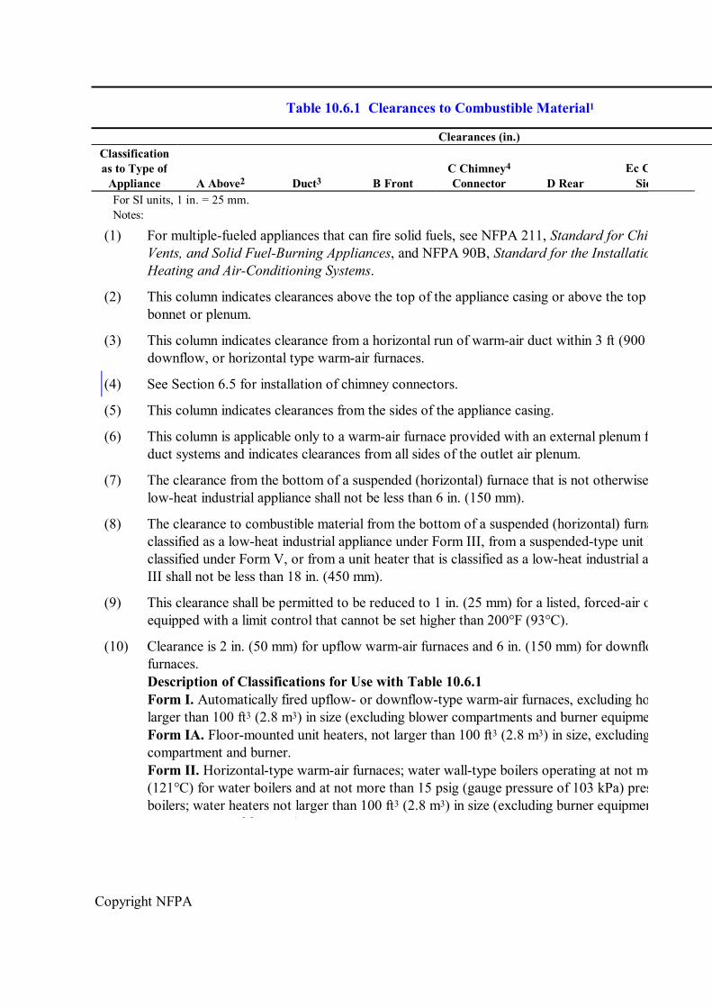
6.5.15 Clearance from combustible construction or materials shall be as specified in Table 10.6.1, except as permitted by 6.5.4 and Table 10.6.2.
6.5.16 The entire length of the chimney connector shall be accessible for inspection, cleaning, and replacement.
6.5.17 Placement of the chimney connector shall maintain minimum fire protection clearances.
6.5.18 A connector shall not be connected to a chimney flue serving a fireplace unless the fireplace opening is sealed or the chimney flue that vents the fireplace is permanently sealed below the connection.
6.5.19 Connectors serving appliances operating under natural draft shall not be connected into any portion of a mechanical draft system operating under a positive pressure.
6.5.20 Connectors for appliances installed in attics or crawl spaces shall be of Type L vent material, or the appliance shall be attached directly to the chimney.
6.5.21 If two or more openings are provided into a chimney flue, they shall be at different levels and the smaller connector shall enter at the higher level consistent with available head room or clearance to combustible material. [211:9.8.4]
6.5.22 Regardless of the fuel(s) used, two or more connectors shall not be joined unless the common connector, the manifold, and the chimney are sized to serve the appliances connected thereto.
6.5.22.1 Adequate draft shall be available to remove all products of combustion to the outdoors without leakage, spillage, or backflow from the connectors, manifold, chimney, or appliances.
6.5.23 Two or more oilburning appliances shall be permitted to be connected to a common venting system, provided the following conditions are met:
(1) Each appliance is equipped with a primary safety control.
(2) The venting system is designed to meet the requirements of the applicable code.
Copyright NFPA
6.5.24 Oilburning appliances that are connected to a common venting system shall be located within the same story of the building unless the vent systems is specifically designed for the purpose and has been approved by the authority having jurisdiction.
6.5.25 Solid fuelburning appliances shall not be connected to a chimney flue serving another appliance burning other fuels, unless specifically listed for such connection. [211:9.8.2]
6.5.26 Gas utilization appliances and appliances burning liquid fuel shall be permitted to be connected to the same chimney flue through separate openings.
6.5.27 Gas utilization appliances and appliances burning liquid fuel shall be permitted to be connected to the same chimney flue through a single opening, provided the appliances are joined by a suitable fitting located as close as practicable to the chimney and provided the following conditions are met:
(1) Sufficient draft is available for the safe combustion of each appliance and for the removal of all products of combustion.
(2) The appliances so connected are equipped with primary safety controls. [211:9.8.3]
6.6 Chimneys.
6.6.1 Masonry and metal chimneys shall be erected in accordance with applicable building code requirements.
6.6.2 Masonry chimneys shall meet the requirements of Chapter 7 of NFPA 211, Standard for Chimneys, Fireplaces, Vents, and Solid Fuel–Burning Appliances.
6.6.3 Metal chimneys shall meet the requirements of Chapter 8 of NFPA 211, Standard for Chimneys, Fireplaces, Vents, and Solid Fuel–Burning Appliances.
6.6.4 Factorybuilt chimneys shall be listed and shall be installed and used in accordance with their listings and with manufacturers' instructions.
6.6.5 Factorybuilt chimneys shall meet the requirements of Chapter 6 of NFPA 211, Standard for Chimneys, Fireplaces, Vents, and Solid Fuel–Burning Appliances.
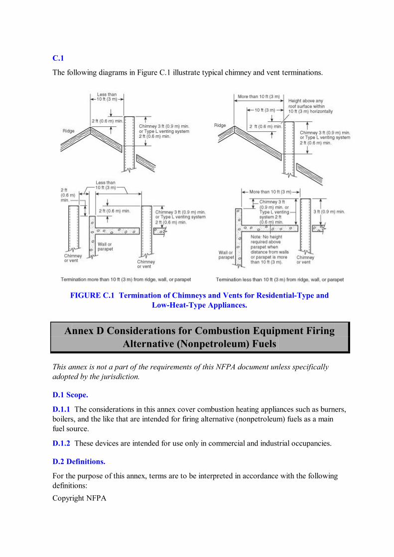
6.6.6* The flue gas exit of a chimney shall be at least 3 ft (0.9 m) above the highest point where it passes through the roof of a building and shall be at least 2 ft (0.6 m) higher than any portion of a building within 10 ft (3 m) of the chimney.
6.6.7* Prior to the installation of a new or replacement oil burner or oilburning appliance, the installer shall perform a visual inspection of the chimney or flue gas venting system.
6.6.7.1 The inspection shall be limited to the cleanout and to the area where the flue gas connector enters the chimney or flue gas venting system and to the extent possible with artificial lighting and conventional tools such as a mirror.
6.6.7.2 If deterioration exists or if the chimney or flue gas venting system is found to inhibit the performance of the oil burner or oilburning appliance, as specified by the manufacturer, the owner shall be notified in writing, stating that the chimney or flue gas venting system to
Copyright NFPA
which the appliance is connected shall be examined by a qualified person in accordance with the requirements of Chapter 14 of NFPA 211, Standard for Chimneys, Fireplaces, Vents, and Solid Fuel–Burning Appliances.
6.6.8* Masonry chimneys shall be lined with an approved clay tile liner or a listed chimney lining system installed in accordance with manufacturers' instructions.
6.6.9* When chimneys are relined, the liner shall be listed or shall be of an approved material that will resist corrosion, softening, or cracking from the flue gases, at a temperature appropriate to the class of service.
6.6.10 All portions of a mechanical draft system under positive pressure during operation shall be designed and installed so as to prevent leakage of flue gas into the building.
6.7 Special Venting Systems.
6.7.1 Type L Venting Systems.
6.7.1.1 Listed Type L venting systems shall be permitted to be used with appliances that are listed as suitable for installation with Type L venting systems.
6.7.1.2 Type L venting systems shall be installed and used in accordance with their listings and the manufacturers' instructions.
6.7.1.3 A Type L venting system shall be capable of producing the minimum draft recommended by the manufacturer of the appliance.
6.7.1.4 The flue gas exit of a Type L venting system shall be at least 2 ft (0.6 m) above the highest point where it passes through the roof of a building and at least 2 ft (0.6 m) higher than any portion of a building within 10 ft (3 m) of such Type L venting system.
6.7.2 Direct Vent Appliances.
6.7.2.1 Direct vent appliances (sealed combustion system appliances) shall be listed and shall be installed in accordance with their listing and with manufacturers' instructions.
6.7.2.2 The combustion air inlet and flue gas outlet of a direct vent appliance shall terminate in the same plane and in the same ambient pressure zone when they terminate in the outside wall of the structure.
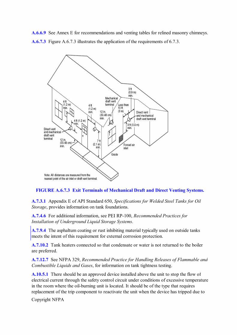
6.7.3* Termination of Special Venting Systems.
6.7.3.1 A venting system that terminates in the sidewall of a structure shall terminate at least 3 ft (0.9 m) above any air inlet to the structure that is within 10 ft (3 m) of the termination point.
Exception No. 1: This requirement shall not apply to the combustion air intake of a direct vent appliance.
Exception No. 2: This requirement shall not apply to the separation distance between the circulating air inlet and the vent discharge of a listed outdoor appliance.
6.7.3.2 The flue gas outlet of an appliance other than a direct vent appliance shall terminate at least 4 ft (1.2 m) below, 4 ft (1.2 m) horizontally from, or 1 ft (0.3 m) above any door,
Copyright NFPA
window, or gravity air inlet of the structure and also shall terminate at least 1 ft (0.3 m) above grade.
6.7.3.3 The combustion air inlet and flue gas outlet of a direct vent appliance or the flue gas outlet of an appliance other than a direct vent appliance shall terminate at least 1 ft (0.3 m) from the soffit of the roof of the structure and at least 3 ft (0.9 m) from an inside corner of an Lshaped structure.
6.7.3.4 The flue gas outlet terminal of a direct vent appliance with an input of 50,000 Btu/hr (0.35 gal/hr) or less shall be located at least 9 in. (225 mm) from any door, window, or air inlet to the structure.
6.7.3.5 The vent terminal of a direct vent appliance with an input over 50,000 Btu/hr (0.35 gal/hr) shall be located at least 1 ft (0.3 m) from any door, window, or air inlet to the structure.
6.7.3.6 Regardless of input, the flue gas outlet terminal shall also terminate at least 1 ft (0.3 m) above grade.
6.7.3.7 The exit terminal of a mechanical draft system shall not be less than 7 ft (2.1 m) above grade when located adjacent to public walkways.
6.7.3.8 Any air inlet and any flue gas outlet of any appliance shall terminate at least 5 ft (1.5 m) from the vent outlet of a liquid fuel supply tank.
6.8 Replacement and Upgrading of Chimneys. (Reserved)
Chapter 7 Fuel Oil Tanks
7.1 Scope.
This chapter shall apply to tanks used to store fuel oil for or to supply fuel oil to oilburning appliances and equipment.
7.2 Basic Design and Construction of Tanks.
7.2.1 Tanks shall be designed, constructed, installed, and used in accordance with sound engineering practice for the construction material used or in accordance with recognized standards of design or approved equivalents.
7.2.2 Tanks shall be approved for the use intended.
7.2.3 Tanks meeting the requirements of Chapter 4 of NFPA 30, Flammable and Combustible Liquids Code, shall be deemed as meeting the requirements of this section.
7.2.4 Tanks shall be constructed of steel or shall be constructed in accordance with 7.2.9. Tanks for underground installation shall be permitted to be constructed of materials other than steel.
7.2.5 Tanks shall be of any shape or type consistent with sound engineering practice.
Copyright NFPA
7.2.6 Tanks shall be permitted to have combustible or noncombustible linings.
7.2.7 Fabrication.
7.2.7.1 Metal tanks shall be welded or brazed or constructed using a combination of these methods.
7.2.7.2 Filler metal used for brazing shall be nonferrous or shall have a melting point above 1000°F (538°C) and below that of the metal being joined.
7.2.7.3 Tanks constructed of other materials shall be fabricated using methods appropriate for the material used.
7.2.8 Operating Pressures.
7.2.8.1 Tanks shall be permitted to be operated at pressures that do not exceed 1 psig (gauge pressure of 7 kPa), measured at the top of the tank, and shall be limited to 2.5 psig (gauge pressure of 17 kPa) under emergency venting conditions.
7.2.8.2 Tanks shall be designed for the maximum static head that will be imposed when the vent or fill pipe is filled with oil, but in no case shall the maximum static head exceed 10 psig (gauge pressure of 70 kPa) at the bottom of the tank.
Exception: Pressure tanks, built in accordance with the principles of the ASME Boiler and Pressure Vessel Code, Section VIII, Division 1 or 2 shall be permitted to exceed 10 psig (gauge pressure of 70 kPa) maximum.
7.2.9 Design Standards.
7.2.9.1 Tanks shall be constructed in accordance with approved standards of design.
7.2.9.2 Atmospheric tanks shall be constructed in accordance with one of the following or its equivalent:
(1) API Standard 650, Specifications for Welded Steel Tanks for Oil Storage
(2) UL 58, Standard for Steel Underground Tanks for Flammable and Combustible Liquids
(3) UL 80, Standard for Steel Inside Tanks for OilBurner Fuel
(4) UL 142, Standard for Steel Aboveground Tanks for Flammable and Combustible Liquids
(5) UL 443, Standard for Steel Auxiliary Tanks for Oil Burner Fuel
(6) UL 1316, Standard for Glass FiberReinforced Plastic Underground Storage Tanks for Petroleum Products
(7) UL 1746, Standard for External Corrosion Protection Systems for Steel Underground Storage Tanks
(8) UL 2080, Standard for Fire Resistant Tanks for Flammable and Combustible Liquids
Copyright NFPA
(9) UL 2085, Standard for Protected Aboveground Tanks for Flammable and Combustible Liquids
(10) UL 2244, Standard for Aboveground Flammable Liquid Tank Systems
(11) UL 2245, Standard for BelowGrade Vaults for Flammable Liquid Storage Tanks
(12) SU 2258, Outline of Investigation for Tanks for Oil Burner Fuel — NonMetallic
7.2.9.3 Tanks larger than 10 gal (38 L) capacity, but not larger than 1320 gal (5000 L), and intended for use inside buildings shall be constructed in accordance with 7.2.9.2(3), 7.2.9.2(4), 7.2.9.2(8), 7.2.9.2(9), or 7.2.9.2(12) or in accordance with the exception to 7.2.8.2.
7.2.9.4 Tanks larger than 1320 gal (5000 L) capacity and intended for use inside buildings shall be constructed in accordance with 7.2.8(4), 7.2.9.2(8), 7.2.9.2(9) or in accordance with the exception to 7.2.8.2.
7.2.9.5 Tanks not larger than 1320 gal (5000 L) and intended for use outside aboveground shall be constructed in accordance with 7.2.9.2(4), 7.2.9.2(8), or 7.2.9.2(9) or in accordance with the exception to 7.2.8.2.
7.2.10 Where a tank is located in an area subject to flooding, the appropriate requirements of NFPA 30, Flammable and Combustible Liquids Code, shall be met.
7.3 Supports and Foundations.
7.3.1* Tanks shall rest on the ground or on foundations made of concrete, masonry, piling, or steel.
7.3.2 Tank foundations shall be designed to minimize the possibility of uneven settling and to minimize corrosion in any part of the tank resting on the foundation.
7.3.3 Where tanks are supported above the foundations, the supports shall be firmly anchored to the foundation and shall be of concrete, masonry, or steel.
7.3.3.1 Single wood timber supports (not cribbing), laid horizontally, shall be permitted to be used for outside aboveground tanks if the supports are less than 12 in. (0.3 m) high at their lowest point.
7.3.4 Steel supports or exposed piling for any outside aboveground tank whose capacity exceeds 660 gal (2500 L) shall be considered protected if they meet one of the following methods and are approved by the authority having jurisdiction:
(1) They are protected by materials having a fire resistance rating of not less than 2 hours.
(2) They are not otherwise protected, but are less than 12 in. (0.3 m) high at their lowest point.
(3) They are protected by a water spray system that meets the requirements of NFPA 15, Standard for Water Spray Fixed Systems for Fire Protection, or NFPA 13, Standard for the Installation of Sprinkler Systems.
Copyright NFPA
7.3.5 Every tank shall be so supported so that excessive concentrations of loads on the supporting portion of the shell are prevented.
7.3.6 In areas subject to earthquake, tank supports and connections shall be designed to resist damage as a result of such shocks.
7.4 Installation of Underground Tanks (including Buried Tanks Under Buildings).
7.4.1 Section 7.4 shall apply to tanks installed underground with backfill and to tanks buried beneath buildings.
7.4.2 Tanks installed underground, including tanks installed under buildings, shall meet the requirements of one of the following:
(1) UL 58, Standard for Steel Underground Tanks for Flammable and Combustible Liquids
(2) UL 1316, Standard for GlassFiber Reinforced Plastic Underground Storage Tanks for Petroleum Products
(3) The exception to 7.2.8.2 of this standard
7.4.3 Excavations for underground tanks shall be made with due care to avoid undermining the foundations of existing structures.
7.4.4 Underground tanks or tanks under buildings shall be located with respect to existing building foundations and supports so that the loads carried by the latter cannot be transmitted to the tank.
7.4.5 The distance from any part of the tank to the nearest wall of any basement, pit, or property line shall not be less than 1 ft (0.3 m).
7.4.6* Underground tanks shall be installed in accordance with manufacturers' instructions and in accordance with all applicable requirements of NFPA 30, Flammable and Combustible Liquids Code, including those for burial depth and cover and for corrosion control.
7.4.7 Underground tanks shall be equipped with an open vent or an automatically operated vent arranged to discharge to the open air.
7.4.8 Vent openings and vent pipes shall be large enough to prevent abnormal pressure in the tank during filling, but not smaller than the pipe size specified in Table 7.4.8.
Table 7.4.8 Diameter of Vent Pipe
Capacity of Tank(s) in U.S. Gallons
Diameter of Vent, Nominal Pipe Size (in.)
660 or less 1¼ 661 to 3,000 1½ 3,001 to 10,000 2 10,001 to 20,000 2½ 20,001 to 35,000 3
Copyright NFPA
Table 7.4.8 Diameter of Vent Pipe
Capacity of Tank(s) in U.S. Gallons
Diameter of Vent, Nominal Pipe Size (in.)
For SI units, 1 gal = 3.785 L, 1 in. = 25 mm.
7.4.9 Where tanks are filled by a pump through tight connections, a vent pipe not smaller in size than the discharge of the pump shall be used.
7.4.10 All connections to an underground tank shall be made through the top of the tank, except as provided for in 9.2.10.
7.4.11 An underground tank shall be provided with means for gauging. (See Section 8.8.)
7.4.12 Underground tanks that are taken out of service shall be removed or permanently closed in accordance with the applicable requirements of NFPA 30, Flammable and Combustible Liquids Code.
7.5 Installation of Tanks Inside Buildings.
7.5.1 Section 7.5 shall apply to fuel storage and supply tanks installed inside buildings, either enclosed or unenclosed, as herein described.
7.5.2 Tanks installed inside buildings shall comply with one of the following as applicable:
(1) UL 80, Standard for Steel Tanks for OilBurner Fuel
(2) UL 142, Standard for Steel Aboveground Tanks for Flammable and Combustible Liquids
(3) UL 443, Standard for Steel Auxiliary Tanks for Oil Burner Fuel
(4) UL 2080, Standard for Fire Resistant Tanks for Flammable and Combustible Liquids
(5) UL 2085, Standard for Protected Aboveground Tanks for Flammable and Combustible Liquids
(6) SU 2258, Outline of Investigation for Tanks for Oil Burner Fuel — NonMetallic
7.5.3 A supply tank of less than 10 gal (38 L) capacity shall be specifically approved for the purpose.
7.5.4 An approved safety can shall be permitted to be used as a temporary fuel oil storage tank.
7.5.5 A tank that exceeds 60 gal (227 L) capacity shall be installed on the lowest floor (story, cellar, or basement) of a building, except as provided for in 7.5.6.
7.5.6 A maximum of 660 gal (2500 L) of storage tank capacity shall be permitted to be installed on a higher floor provided the following conditions are met:
Copyright NFPA
(1) The higher floor does not have any floor or open space directly below it.
(2) The higher floor is provided with a liquidtight sill, containment device, or equivalent means having the ability to hold a minimum of 15 percent of the aggregate tank capacity to prevent spilled fuel oil from entering an adjacent, lower area.
7.5.7 A tank of less than 10 gal (38 L) capacity shall not be placed within 2 ft (0.6 m) horizontally from any source of heat, either in or external to the appliance being served, nor shall it be placed in a manner such that the temperature of the oil in the tank exceeds the temperature of its surroundings by 25°F (14°C) or more.
7.5.8 Tanks of a capacity between 10 gal and 1320 gal (38 L and 5000 L) shall not be placed within 5 ft (1.5 m) horizontally from any source of heat, either in or external to any liquid fuelburning appliance, unless separated from the source of heat by a barrier having a 1hour fire resistance rating extending horizontally at least 1 ft (0.3 m) past the oil burner or oil tank, whichever is greater, and extending vertically from floor to ceiling.
7.5.9 A tank of a capacity between 10 gal and 330 gal (38 L and 1250 L) that is provided with an opening in the bottom for use as an appliance supply connection or as a drain shall be arranged as follows:
(1) The tank shall be pitched toward the opening with a slope of not less than ¼ in./ft (20 mm/m) or every 5 ft of length.
(2) The supply line shall be provided with a readily accessible, thermally operated springloaded shutoff valve installed as close as practical to the tank. (See also 8.6.4.)
(3) A properly sized and rated oil filter or strainer shall be installed in the oil supply line to an oil burner immediately after the thermally operated springloaded shutoff valve required by 7.5.9(2).
(4) Where three or more tanks are installed as part of a fuel storage system, each burner supply line shall be provided with a readily accessible oil safety valve.
7.5.10 All supply connections to a tank of capacity greater than 330 gal (2500 L) shall be made through the top of the tank, and the transfer of oil shall be by pump through continuous piping to and from the consuming appliance(s).
7.5.11 Each tank or tank system shall be equipped with fill and vent pipes, both of which shall terminate outside the building.
7.5.11.1 The size and type of the vent pipe shall be as specified in Table 7.5.11.1.
Table 7.5.11.1 Type and Size of Vents
Tank Capacity in U.S. Gal Type of Vent
Size of Vent (nominal inside diameter)
10 to 660 Open vent pipe Minimum 1¼ in. Greater than 660 Open vent or automatically
operated vent Sized to prevent abnormal pressure in the tank during filling, but not smaller than the pipe size specified in Table 7.4.8
Copyright NFPA
Table 7.5.11.1 Type and Size of Vents
Tank Capacity in U.S. Gal Type of Vent
Size of Vent (nominal inside diameter)
For SI units, 1 gal = 3.785 L, 1 in. = 25 mm.
7.5.11.2 The vent pipe shall be at least as large as the largest fill or withdrawal connection to the tank, but in no case shall it be less than 1¼ in. (32 mm) nominal inside diameter.
7.5.12 Each tank shall be equipped with a gauging device. (See Section 8.8.)
7.5.13 Any unused opening in a tank shall be closed vaportight by a threaded plug or cap.
7.5.14 Each tank shall be securely supported by rigid noncombustible supports to prevent settling, sliding, or lifting.
7.5.15 A tank or tank system shall be permitted to supply more than one oilburning appliance.
7.5.16 Where a tank or tank system is not located in a dedicated room or enclosure, the maximum capacity in the building shall not exceed 1320 gal (5000 L) for a nonengineered system and shall not exceed 1375 gal (5200 L) for an engineered system, unless the installation meets the criteria in 7.5.16.1 or 7.5.16.2.
7.5.16.1 Fuel tanks of any size shall be permitted within engine rooms or mechanical spaces, provided the engine or mechanical room is designed using recognized engineering practices with suitable fire detection, fire suppression, and containment means to prevent the spread of fire beyond the room of origin.
7.5.16.2 Where a tank or tank system is not located in a dedicated room or enclosure, but is separated from other tank(s) by construction having a fire resistance rating of at least 2 hours, the maximum capacity in each separate area shall not exceed 1320 gal (5000 L) for a nonengineered system and shall not exceed 1375 gal (5200 L) for an engineered system. The maximum total capacity in the building shall not be limited.
7.5.17 Where a tank or tank system is located in a dedicated room or enclosure that is separated from the rest of the building by construction having a fire resistance rating of at least 1 hour, the maximum total capacity in the room shall not exceed 1320 gal (5000 L).
7.5.18 Where a tank or tank system is located in a dedicated room or enclosure that is separated from the rest of the building by construction having a fire resistance rating of at least 3 hours, the maximum total capacity in the room shall be permitted to exceed 1320 gal (5000 L) for a nonengineered system and 1375 gal (5200 L) for an engineered system.
7.5.19 Dedicated rooms or enclosures shall meet all applicable requirements of Section 7.6.
7.5.20 Tanks shall not obstruct quick and safe access to any utility service meters, electrical panelboards, or shutoff valves.
7.6 Requirements for Dedicated Tank Rooms and Tank Enclosures.
Copyright NFPA
7.6.1 Each tank room or tank enclosure shall have a doorway with a noncombustible liquidtight sill or ramp at least 6 in. (150 mm) high and a selfclosing, listed fire door that meets the requirements of NFPA 80, Standard for Fire Doors and Fire Windows.
7.6.2 Fire doors for rooms or enclosures of 2hour fireresistant construction shall have a fire protection rating of 1½ hours.
7.6.3 Fire doors for rooms or enclosures of 3hour fireresistant construction shall have a fire protection rating of 3 hours.
7.6.4 If the sill or ramp is more than 6 in. (150 mm) high, walls shall be built to a height corresponding to the level of oil that will be retained in order to withstand the lateral pressure due to the liquid head.
7.6.5 Each tank room or tank enclosure shall be provided with means to ventilate the enclosure prior to entering for inspection or repair.
7.6.6 A tank installed in a room or area having a fire resistance rating of 2 hours or less shall be of such size and shape that it can be installed in and removed from the room or area and from the building as a unit (i.e., in one piece).
7.7 Piping Arrangements and CrossConnections.
7.7.1 Crossconnection of two tanks of not more than 660 gal (2500 L) aggregate capacity to the same oilburning appliance(s) shall be permitted when the fill and vent piping and the oil supply line to the appliance(s) is installed in accordance with Figure 7.7.1.
Copyright NFPA
FIGURE 7.7.1 CrossConnection of Two Fuel Oil Tanks of Not More than 660 gal (2500 L) Aggregate Capacity.
7.7.2 Crossconnection of three tanks of not more than 990 gal (3750 L) aggregate capacity to the same oilburning appliance(s) shall be permitted when the fill and vent piping and the oil supply line to the appliance(s) is installed in accordance with Figure 7.7.2.
Copyright NFPA
FIGURE 7.7.2 CrossConnection of Three Fuel Oil Tanks of Not More Than 990 gal (3750 L) Aggregate Capacity.
7.7.3 Crossconnection of four tanks of not more than 1320 gal (5000 L) aggregate capacity to the same oilburning appliance(s) shall be permitted when the fill and vent piping and the oil supply line to the appliance(s) is installed in accordance with Figure 7.7.3.
Copyright NFPA
FIGURE 7.7.3 Cross Connection of Four Fuel Tanks of Not More Than 1320 gal (5000 L) Aggregate Capacity.
7.7.4 Where two or more tanks are manifolded as part of a listed fuel storage system or an engineered fuel storage system, installation shall be by a qualified person and shall be installed in accordance with the manufacturer's instructions. (See also 8.6.1 and 8.6.2.)
7.8 Auxiliary Tanks.
7.8.1 An auxiliary tank shall be filled by pump transfer through continuous piping from the supply tank.
7.8.2 An auxiliary tank shall be located at a level above the top of the supply tank from which it is filled.
7.8.3 An auxiliary tank shall be provided with an overflow pipe draining to the supply tank and extending into the top of the supply tank not more than 1 in. (25 mm), unless the auxiliary tank is specifically listed for use without an overflow pipe.
7.9 Installation of Outside Aboveground Tanks.
7.9.1 Section 7.9 shall apply to tanks that are installed aboveground outside of buildings. This section shall not apply to a centralized oil distribution system.
7.9.2 A tank or tanks whose capacity does not exceed 660 gal (2500 L) shall be permitted to be installed outside of and adjacent to a building, provided they are separated from the
Copyright NFPA
nearest line of adjoining property by the following minimum distance:
(1) 5 ft (1.5 m) for tanks not exceeding 275 gal (1040 L) capacity
(2) 10 ft (3 m) for tanks greater than 275 gal (1040 L) capacity, but not exceeding 660 gal (2500 L) capacity
7.9.3 A tank or tanks whose capacity exceeds 660 gal (2500 L) shall be installed in accordance with all applicable requirements of NFPA 30, Flammable and Combustible Liquids Code.
7.9.4* Outside aboveground tanks and their appurtenances and supports shall be protected from external corrosion.
7.9.5 Crossconnection of two tanks to the same burner or the same group of burners shall be permitted. The tanks shall be permitted to have a single fill pipe and a single vent and shall be rigidly secured to a common slab or foundation.
7.9.6 Tanks shall be securely supported by rigid noncombustible supports to prevent settling, sliding, or lifting.
7.9.7 Each oil burner supply line connected to the gravity feed connection of the supply tank shall be provided with a shutoff valve at the tank.
7.9.7.1 Where this supply line passes through a foundation immediately inside the building, a readily accessible thermally operated springloaded valve shall be installed before the oil filter.
7.9.8 Each tank shall be equipped with an open vent not smaller than the pipe size specified in Table 7.4.8.
7.9.9 Each tank shall be provided with a means to determine the liquid level. (See Section 8.8.)
7.9.10 Each tank shall have a fill opening that is of such size and so located as to permit ready filling in a manner that avoids spills.
7.9.11 Filling a portable container from a tank greater than 60 gal (227 L) shall be done by hand pump only.
7.10 Tank Heating Systems.
7.10.1 Where tanks are provided with heating systems to maintain oil at the required temperature for proper atomization, the heating systems shall meet the requirements in 7.10.2 through 7.10.5, as applicable.
7.10.2* Where tanks are heated by steam coils, the maximum operating pressure of the steam coils shall not exceed 15 psig (gauge pressure of 105 kPa).
7.10.2.1 Where a pressurereducing valve is used to limit the steam pressure to 15 psig (gauge pressure of 105 kPa) or less, the following shall apply:
(1) A relief valve set at not more than 5 psig (gauge pressure of 35 kPa) above the
Copyright NFPA
normal pressure in the coil shall be provided.
(2) Provision shall be made to limit the steam temperature to 250°F (121°C).
7.10.3 Where tanks are heated by hot water coils, the hot water shall be provided by indirect heaters and the maximum temperature of the water shall be limited to 250°F (121°C).
7.10.4 Where tanks are heated by electric heaters, the heaters shall be equipped with approved thermostats designed to prevent the oil from exceeding its minimum flash point.
7.10.5 Where heaters are installed in an oil tank, provisions shall be made to prevent the oil level in the tank from dropping to a point that exposes the surface of the heater.
7.11 Special Storage Arrangements.
In particular installations, the provisions of Chapter 7 shall be permitted to be altered by the authority having jurisdiction after consideration of special features such as topographical conditions, barricades, walls, nature of occupancies, and proximity to buildings or adjoining property; height and character of construction of such buildings; capacity and construction of proposed tanks; character of liquids to be stored; degree of private fire protection to be provided; and the adequacy of facilities of the fire department to cope with fuel oil fires.
7.12 Testing and Maintenance.
7.12.1 All tanks, whether shopbuilt or fielderected, shall be tested before they are placed in service in accordance with the applicable standard under which they were built.
7.12.1.1 The ASME code stamp or a listing mark acceptable to the authority having jurisdiction shall be evidence of compliance with this test.
7.12.1.2 Tanks not marked in accordance with 7.12.1.1 shall be tested before they are placed in service in accordance with good engineering principles.
7.12.2 Where the vertical length of the fill and vent pipes is such that the static head imposed on the bottom of the tank when the tank is filled exceeds 10 psig (gauge pressure of 70 kPa), the tank and related piping shall be tested hydrostatically to a pressure equal to the static head thus imposed (i.e., on bottom of tank).
7.12.3 In cases where the height of the vent above the top of the tank is excessive, the hydrostatic test pressure shall be determined by using recognized engineering practice.
7.12.4 In addition to the tests called for in 7.12.2 and 7.12.3, all tanks and connections shall be tested for tightness.
Exception: Listed tanks that do not exceed 1320 gal (5000 L) shall not be required to meet this requirement.
7.12.4.1 Except for underground tanks, this tightness test shall be made at operating pressure with air, inert gas, or water prior to placing the tank in service.
7.12.4.2 In the case of fielderected tanks, the test called for in 7.12.2 and 7.12.3 shall be considered to be the tightness test.
Copyright NFPA
7.12.4.3 Singlewall underground tanks and piping, before being covered, enclosed, or placed in service, shall be tested for tightness hydrostatically or with air pressure at not less than 3 psig (gauge pressure of 21 kPa) and not more than 5 psig (gauge pressure of 35 kPa). (See Section 8.9 for testing of piping systems.)
7.12.4.4 Secondary containment tanks shall have the primary (inner) tank tested according to 7.12.4.3 and the interstitial space (annulus) tested using air at 3 psig to 5 psig (gauge pressure of 21 kPa to 35 kPa) or vacuum at 5.3 in. Hg (gauge pressure of 18 kPa).
7.12.4.4.1 The pressure or vacuum shall be held for 1 hour.
7.12.4.4.2 Care shall be taken to ensure that the interstitial space is not overpressured or subjected to excessive vacuum.
7.12.4.5 Tanks to be operated at pressures below their design pressure shall be permitted to be tested by the applicable provisions of 7.12.2 and 7.12.3 based on the pressure developed under full emergency venting of the tank.
7.12.5 Each tank shall be maintained liquidtight.
7.12.6 Each tank that is leaking shall be emptied of liquid or repaired in an approved manner.
7.12.7* Each underground tank that has been repaired or altered or is suspected of leaking shall be tested in an approved manner.
7.13 Fuel Oil Storage Systems That Are Permanently or Temporarily Taken Out of Service.
7.13.1 If an oil storage tank is permanently removed from service, for whatever reason, for the tank and all piping connected to it, including the outside fill and vent piping and any piping connected to the appliance, the following criteria shall be met:
(1) They shall be emptied of all contents.
(2) They shall be cleaned and rendered free of combustible vapors.
(3) They shall be removed from the premises or property.
(4) They shall be properly disposed of in accordance with all applicable local, state, and federal rules and regulations.
7.13.2 If an oil storage tank is temporarily removed from service, for whatever reason, for the tank and all piping connected to it, including the outside fill and vent piping and any piping connected to the appliance, the following criteria shall be met:
(1) They shall be emptied of all contents.
(2) They shall be cleaned and rendered free of combustible vapors.
7.13.2.1 In addition to the requirements of 7.13.2, all manways shall be locked or bolted securely.
7.13.2.2 In addition to the requirements of 7.13.2, all fill lines shall be plugged to prevent
Copyright NFPA
use by one of the following methods:
(1) The fill lines shall be filled with concrete.
(2) The caps of the fill lines shall be welded shut.
(3) The fill pipes shall be completely removed.
7.13.2.3 In addition to the requirements of 7.13.2, the supply line to the appliance shall be disconnected and capped or plugged.
7.13.2.4 In addition to the requirements of 7.13.2, all vent lines shall remain open.
7.13.2.5 In addition to the requirements of 7.13.2, aboveground tanks shall be protected from flotation in accordance with sound engineering practice.
7.13.3 The remover/installer of a tank permanently or temporarily taken out of service shall submit an affidavit of compliance to the authority having jurisdiction or to the tank owner that such oil storage system was removed, or closed and sealed in compliance with this requirement.
7.14 Permanent Abandonment of Underground Tanks.
If an underground oil storage tank is permanently removed from service, the requirements of 4.6.5 of NFPA 30, Flammable and Combustible Liquids Code, shall apply.
Chapter 8 Fuel Piping Systems and Components
8.1 Scope.
This chapter shall apply to piping systems and their components used to transfer fuel oil from storage and supply tanks to oilburning appliances and equipment.
8.2 Acceptable Piping Materials and Piping System Design.
8.2.1 Tank fill and vent piping shall be wroughtiron, steel, or Schedule 40 brass pipe.
8.2.2 Oil supply lines shall be steel pipe or brass or copper tubing.
8.2.3 Wall thickness of wroughtiron and steel pipe shall comply with the specifications in ANSI/ASME B36.10M, Standard on Welded and Seamless Wrought Steel Pipe.
8.2.4 Piping shall be permitted to be of materials other than those specified in 8.2.1, 8.2.2, and 8.2.3 if used underground and backfilled or if used as part of an engineered fuel storage system.
8.2.4.1 Such piping shall be designed in accordance with good engineering practice for the material used and shall be approved by the authority having jurisdiction.
8.2.4.2 Such piping shall be installed in accordance with manufacturers' instructions.
8.2.5 Listed flexible metal hose shall be permitted to be used where rigid connections are
Copyright NFPA
impractical, provided it is installed in full compliance with its listing.
8.2.6 Piping used to connect oil burners and oilburning appliances to their fuel supply shall not be smaller than in. (9.5 mm) iron pipe size or in. (9.5 mm) O.D. tubing.
8.2.7 Copper tubing shall have 0.035 in. (0.9 mm) nominal and 0.032 in. (0.81 mm) minimum wall thickness.
8.2.8 Pipe shall be connected with standard malleable iron fittings, and tubing shall be connected with fittings of listed types.
8.2.8.1 Pipe connectors made of combustible materials or dependent on the frictional characteristics of combustible materials shall not be used inside of buildings or aboveground outside of buildings.
8.2.8.2 Connectors described in 8.2.8.1 shall be permitted to be used underground if of listed type and installed in accordance with their listing.
8.2.8.3 All threaded joints and connections shall be made tight with suitable lubricant or pipe compound.
8.2.8.4 Unions requiring gaskets or packings, right or left couplings, and sweat fittings employing brazing material having a melting point of less than 1000°F (538°C) shall not be used in oil lines.
8.2.8.5 Castiron fittings shall not be used.
8.2.9 Piping shall meet the following criteria:
(1) Piping shall be substantially supported and protected against physical damage.
(2) Piping shall be protected against corrosion.
8.2.10 Proper allowance shall be made for expansion, contraction, jarring, and vibration.
8.2.11 Pipe lines connected to underground tanks shall be provided with double swing joints or flexible connectors or shall be otherwise arranged to permit the tanks to settle without impairing the tightness of the pipe connections.
8.2.11.1 Tubing shall not be required to meet the requirements of 8.2.11.
8.2.11.2 Straight fill lines and test wells that have no changes in direction shall not be required to meet the requirements of 8.2.11.
8.2.12 Piping systems shall be maintained liquidtight.
8.2.12.1 A piping system that leaks shall be emptied of liquid or repaired in an approved manner.
8.2.13 Fuel oil shall not be transferred to an oilburning appliance by pressurizing the tank with air or other gas.
8.3 Tank Fill Piping.
Copyright NFPA
8.3.1 The fill pipe shall be large enough and so located as to permit ready filling in a manner that minimizes spills.
8.3.2 The fill pipe shall terminate as follows:
(1) Outside the building at a point at least 2 ft (0.6 m) from any building opening at the same or lower level
(2) In a manner that minimizes spills when the filling hose is disconnected
8.3.3 A crankcase oil or used oil fill pipe for a tank directly serving a used oil fired burner and appliance shall be permitted to terminate indoors in accordance with NFPA 30A, Code for Motor Fuel Dispensing Facilities and Repair Garages.
8.3.3.1 If the fill pipe specified in 8.3.3 has a funneltype opening, then it shall be provided with a readily accessible manual shutoff valve of the quarterturntoclose type, between the funneltype opening and the tank.
8.3.4 The end of the fill pipe shall be equipped with a tight metal cover designed to discourage tampering and shall be identified as a fuel oil fill.
8.3.5 The following shall apply to crossconnections:
(1) Crossconnections that allow gravity flow from one tank to another shall be prohibited.
(2) Two supply tanks whose aggregate capacity does not exceed 660 gal (2500 L) shall be permitted to be crossconnected as specified in Section 7.7.
8.4 Piping for Auxiliary Tanks.
An overflow pipe from an auxiliary tank shall have no valves or obstructions.
8.5 Fuel Return Piping.
A return line from a burner or pump to a supply tank shall have no valves or obstructions and shall enter the top of the same tank.
8.6 Supply Piping to OilBurning Appliances.
8.6.1 The supply piping from a tank that exceeds 330 gal (1250 L) capacity shall be connected to the top of the tank.
8.6.2 The crossconnection between two tanks having an aggregate capacity that does not exceed 660 gal (2500 L) shall not be required to meet the requirement of 8.6.1.
8.6.3 The pressure at the oil supply inlet to an oilburning appliance shall not exceed 3 psig (gauge pressure of 21 kPa), unless the appliance is approved for a higher inlet pressure.
8.6.4 A readily accessible, thermally operated, springloaded shutoff valve shall be installed as close as practical to the burner(s) supply connection. [See also 7.5.9(2).]
8.6.5 Where supply tanks are set below the level of the burner, the oil piping shall pitch
Copyright NFPA
toward the supply tank.
8.6.6 For commercial and industrial installations, the oil supply from tanks of any capacity permitted by this standard shall meet the following requirements:
(1) The burner supply line shall be permitted to be connected to an outside aboveground supply tank at a point below the liquid level, but each such connection shall be provided with an internal or external shutoff valve located as close as practicable to the shell of the tank.
(2) External valves and their connections to the tank shall be of steel.
(3) A transfer pump shall be permitted to be used.
8.7 Vent Piping.
8.7.1 Vent pipes shall drain toward the tank or toward one tank where two tanks are crossconnected.
8.7.2 The vent pipes shall have no sags or traps where liquid can collect.
8.7.3 Vent pipes shall be located so that they are not subjected to physical damage.
8.7.4 The lower end of the vent pipe shall enter the tank through the top and shall extend into the tank not more than 1 in. (25 mm).
8.7.5 All vent pipes shall terminate outside of buildings at a point not less than 2 ft (0.6 m) measured vertically or horizontally from any building opening.
8.7.5.1 Vent pipes shall terminate high enough above the ground to avoid being obstructed with snow and ice.
8.7.5.2 Vent pipes shall terminate not more than 12 ft (3.6 m) from the fill pipe on the same side of building.
8.7.6 The outer end of the vent pipe shall terminate in a weatherproof vent cap or fitting or shall be provided with a weatherproof hood.
8.7.7 Vent caps shall have a minimum free open area equal to the crosssectional area of the vent pipe and shall not employ screens finer than No. 4 mesh.
8.7.8 Vent pipes from tanks containing heaters shall extend to a location where oil vapors discharging from the vent will be readily diffused.
8.7.9 If the static head with a vent pipe filled with oil exceeds 10 psig (gauge pressure of 70 kPa), the tank shall be designed to withstand the maximum static head that will be imposed.
8.7.10 Vent pipes from more than one tank shall be permitted to be manifolded and connected into one outlet pipe.
8.7.10.1 The outlet pipe shall be at least one pipe size larger than the largest individual vent pipe connected thereto.
8.7.10.2 In no case shall the point of connection between two or more vent pipes be lower
Copyright NFPA
than the top of any fill pipe opening.
8.7.11 The vent outlet of a supply tank shall terminate at least 5 ft (1.5 m) from any air inlet or any flue gas outlet of any appliance.
8.7.12 Vent pipes shall not be crossconnected with pipes other than vent pipes.
8.8 Pumps, Valves, Gauges, and Appurtenances.
8.8.1 Tanks in which a constant oil level is not maintained by an automatic pump shall be equipped with a method of determining the oil level.
8.8.2 Gauging devices, such as liquid level indicators or signals, shall be designed and installed so that oil or vapor will not be discharged into a building.
8.8.3 Inside tanks provided with fill and vent pipes shall be provided with a device to indicate at the fill point, either visually or audibly, when the oil in the tank has reached a predetermined safe level.
8.8.4 Supply tanks shall not be equipped with a glass gauge or any type of gauge that, when broken, will permit the escape of oil from the tank.
8.8.5 An oil pump that is not a part of a listed burner shall be a positive displacement type that automatically shuts off the oil supply when stopped.
8.8.6 An automatic pump that is not an integral part of a burner shall be a listed type installed in full compliance with its listing.
8.8.7 A readily accessible, thermally operated, springloaded shutoff valve shall be installed at each point where required and shall be installed so that it closes against the supply pressure.
8.8.8 Where a shutoff is installed in the discharge line of an auxiliary oil supply pump that is not an integral part of a burner, a pressure relief valve shall be connected into the discharge line between the pump and the shutoff valve and shall be arranged to return surplus oil to the supply tank or to bypass it around the pump.
8.8.8.1 Pumps having an internal bypass valve shall not be required to meet the requirement of 8.8.8.
8.8.9 A fuel oil line incorporating a heater shall be provided with a pressure relief valve arranged to discharge to the return line when any valve, pump, or other device could prevent the release of excessive pressure because of the expansion of the heated oil.
8.8.10 Where oil is supplied by gravity feed to a burner requiring uniform flow and a constant level valve is not incorporated in the burner assembly or the oil is not supplied by an automatic pump, the following requirements shall be met:
(1) A constant level valve shall be installed in the supply line at the gravity tank or as close thereto as practicable to ensure uniform delivery of oil to the burner.
(2) If the constant level valve is not provided with an antiflooding device, the vent opening of the constant level valve shall be connected by piping or tubing to the
Copyright NFPA
outside of the building.
(3) Vent piping or tubing from a constant level valve shall not be connected to a tank or to a tank vent.
8.8.11 Provision shall be made for adequate ventilation of enclosures, such as tank rooms, tank enclosures, or pits where pumps and accessories are installed, prior to entering for inspection or repair.
8.8.12 Test wells shall not be installed inside buildings.
8.8.13 Test wells installed outside shall be equipped with a tight metal cover designed to discourage tampering.
8.9 Testing.
8.9.1 Unless piping and all fittings are visible for inspection, piping shall be tested before being covered, enclosed, or placed in use.
8.9.1.1 Testing shall be done hydrostatically to 150 percent of the maximum anticipated pressure of the system or pneumatically to 110 percent of the maximum anticipated pressure of the system.
8.9.1.2 The test pressure shall be maintained for a sufficient time to conduct a complete visual inspection of all joints and connections.
8.9.1.3 In no case shall the test pressure be less than a gauge pressure of 5 psig (35 kPa), measured at the highest point of the system, and in no case shall the test pressure be maintained for less than 10 minutes.
8.9.1.4 The test shall be made so as not to impose a pressure of more than 5 psig (gauge pressure of 35 kPa) on any tank connected to the piping.
8.9.1.5 Pressure shall be maintained for at least 30 minutes or for sufficient time to complete visual inspection of all joints and connections.
8.9.1.6 Suction lines shall be permitted to be tested under a vacuum of not less than 20 in. Hg (68 kPa) maintained for at least 30 minutes.
8.9.2 Where the vertical length of the fill and vent pipes is such that, when filled with liquid, the static head imposed exceeds 10 psig (gauge pressure of 70 kPa), the piping shall be tested hydrostatically to a pressure equal to the static head thus imposed. (See 7.2.8.2.)
Chapter 9 Oil Distribution Systems
9.1 Scope.
This chapter shall apply to centralized oil distribution systems, as defined in 3.3.8, and to oil distribution systems for roofmounted and ceilingsuspended oilburning appliances.
9.2 Centralized Oil Distribution Systems.
Copyright NFPA
9.2.1 A centralized oil distribution system shall meet the requirements of this section and all other applicable provisions of this standard.
9.2.2 The installation and maintenance of a centralized oil distribution system shall be supervised by a qualified person.
9.2.3 Plans showing the relative location of tanks, pumps, valves, piping, and structures to be supplied by the system shall be approved by and filed with the authority having jurisdiction.
9.2.4 Oil shall be permitted to be fed from the supply tank or tanks by gravity or by transfer pump.
9.2.5 All distribution piping outside of diked areas shall be underground.
9.2.6 The capacity of a single aboveground tank or the aggregate capacity of two or more aboveground tanks supplying a centralized oil distribution system shall not exceed 20,000 gal (75,700 L) nominal capacity.
9.2.7 Underground tanks installed in accordance with Section 7.4 shall be permitted to be of any capacity.
9.2.8 Tanks that supply a centralized oil distribution system shall meet all applicable requirements of Chapter 7.
9.2.9 Aboveground tanks shall be provided with spill control by means of diking meeting the requirements of NFPA 30, Flammable and Combustible Liquids Code.
9.2.10 The main distribution pipeline shall be permitted to be connected to a tank or tanks having an aggregate capacity not exceeding 20,000 gal (75,700 L) at a point below the liquid level.
9.2.10.1 Where this piping is so connected, a readily accessible internal or external shutoff valve shall be installed in the piping as close as practicable to the tank.
9.2.10.2 If external and aboveground, the shutoff valve and its tank connections shall be made of steel.
9.2.10.3 Connections between the tank(s) and the main pipeline shall be made with double swing joints or flexible connectors, or shall otherwise be arranged to permit the tank(s) to settle without damaging the system.
9.2.10.4 If located aboveground, the connections specified in 9.2.10.3 shall be located within the diked area.
9.2.11 A readily accessible and identified manual shutoff valve shall be installed either inside or outside of the structure in each branch supply pipeline that enters a building, mobile home, travel trailer, or other structure.
9.2.11.1 If inside, the valve shall be located directly adjacent to the point at which the supply line enters the structure.
9.2.11.2 If outside, the valve shall be protected from weather and damage.
Copyright NFPA
9.2.12 A device shall be provided in the supply line at or ahead of the point where it enters the interior of the structure that will automatically shut off the oil supply, if the supply line between this device and the appliance is broken.
9.2.12.1 This device shall be located on the appliance side of the manual shutoff valve required in 9.2.11 and shall be solidly supported and protected from damage.
9.2.13 Means shall be provided to limit the oil pressure at the appliance inlet to a maximum of 3 psig (gauge pressure of 21 kPa).
9.2.13.1 If a pressurereducing valve is used, it shall be a type approved for the service.
9.2.14 A device shall be provided that will automatically shut off the oil supply to the appliance if the oil pressure at the appliance inlet exceeds 8 psig (gauge pressure of 55 kPa). The device shall not be required under either of the following conditions:
(1) Where the distribution system is supplied from a gravity tank and the maximum hydrostatic head of oil in the tank is such that the oil pressure at the appliance inlet will not exceed 8 psig (gauge pressure of 55 kPa)
(2) Where a means is provided to automatically shut off the oil supply if the pressureregulating device provided in accordance with 9.2.13 fails to regulate the pressure as required
9.2.15 Only appliances equipped with primary safety controls specifically listed for the appliance shall be connected to a centralized oil distribution system.
9.2.16 Accurate inventory records shall be maintained and reconciled on all storage tanks for indication of leakage from tanks or piping.
9.3 Oil Distribution Systems for RoofMounted or CeilingSuspended OilFired Units.
9.3.1 An oil distribution system for roofmounted or ceilingsuspended oilburning appliances shall meet the requirements of this section and all other applicable provisions of this standard.
9.3.2 The installation and maintenance of the oil distribution system shall be supervised by a qualified person.
9.3.3 Plans showing the relative location of tanks, pumps, valves, piping, and their relationship to structures supplied by the systems shall be approved by and filed with the authority having jurisdiction.
9.3.4 Oil shall be permitted to be fed to the burner(s) directly from a storage tank or by means of a fuel distribution system that includes a transfer pump.
9.3.4.1 Where fed directly from a storage tank, the fuel supply system shall be designed so that the burner fuel unit operates with less than 10 in. Hg (34 kPa) vacuum at the inlet under normal operating conditions.
9.3.4.2 If the requirements of 9.3.4.1 cannot be met, a fuel supply system incorporating a transfer pump(s) shall be provided.
Copyright NFPA
9.3.5 The fuel supply system shall meet the following requirements:
(1) All components (pumps, reservoirs, valves, regulators, relief valves, controls, and so forth) shall be listed for use with fuel oil.
(2) Control and relief provisions shall be provided to prevent pressurizing the main distribution pipelines to any point more than 50 percent above the normal working pressure.
(3) Deadended main distribution pipelines shall not be permitted unless provisions are made for air purging, and the purge points shall be closed by plugs or caps when not actually in use.
(4) Means shall be provided to limit the oil pressure at the burner inlet to a maximum of 3 psig (gauge pressure of 21 kPa).
(5) If a pressurereducing valve is to be used, it shall be a type approved for the service.
9.3.6 The capacity of a single aboveground tank or the aggregate capacity of two or more aboveground tanks shall not exceed 20,000 gal (75,700 L) nominal capacity.
9.3.7 Underground tanks installed in accordance with Section 7.4 shall be permitted to be of any capacity.
9.3.8 Tanks, piping, pumps, and valves shall meet all applicable requirements of Chapters 7 and 8.
9.3.9 If required by design, individual supply tanks, including auxiliary tanks, connected to burners shall meet the requirements of 7.5.5, 7.8.2, 7.8.3, and Section 8.4.
9.3.10 Valves and drip trays (roofmounted units only) shall be provided to prevent oil spills during servicing.
9.3.11 A readily accessible and identified manual shutoff valve shall be installed in each branch supply pipeline that serves an individual burner and in the oil distribution line.
9.3.11.1 This valve shall be permitted to be either inside or outside of a protective enclosure.
9.3.11.2 If inside, the valve shall be located directly adjacent to the point at which the supply line enters the protective enclosure.
9.3.11.3 If outside, the valve shall be protected from weather and damage.
9.3.12 Only roofmounted or ceilingsuspended appliances equipped with primary safety controls specifically listed for the appliance shall be connected to the distribution system.
9.3.13 A switch shall be provided in the electrical supply to the transfer pump.
9.3.13.1 The switch shall be permitted to be locked in the open position and shall be located at a convenient location so the fuel supply system can be shut down for maintenance.
9.3.13.2 Provisions shall be made so that shutdown of the fuel supply system interrupts the electrical supply to the appliances to which the fuel supply is connected. (See also 10.5.9.)
Copyright NFPA
Chapter 10 Installation of Oil Burners and OilBurning Appliances
10.1 Scope.
This chapter shall apply to installation of oil burners and oilburning appliances and equipment.
10.2 Basic Requirements.
10.2.1 Installation of oilburning boilers with inputs of 12,500,000 Btu/hr (3663 kW) and above shall meet the applicable requirements of NFPA 85, Boiler and Combustion Systems Hazards Code.
10.2.2 Installation of oilburning ovens and furnaces within the scope of NFPA 86, Standard for Ovens and Furnaces, and shall meet the applicable requirements of that standard.
10.2.3 Oil burners shall be permitted to be installed in boilers and furnaces.
10.2.4 Oil burners shall be permitted by the authority having jurisdiction for use in firing ovens, water heaters, ranges, special furnaces, and the like.
10.2.5 Where oil burners are installed in appliances originally designed for solid fuel, the ash door of the appliance shall be removed or bottom ventilation shall be provided to prevent the accumulation of vapors in the ash pit.
Exception: Where the ash pit is used as part of the combustion chamber.
10.2.6 Oilburning appliances shall be installed in rooms that are large compared with the size of the appliance.
Exception: An appliance specifically listed for installation in a confined space, such as an alcove or closet, shall be permitted to be so installed when the installation complies with its listing.
10.2.7 In installations in confined spaces, the clearances from the appliance to the walls and ceilings shall not be less than those specified in the listing, regardless of the type of construction.
10.2.8 The oilburning appliance shall have a suitable combustion chamber of firebrick, stainless steel, or other material, either furnished by the manufacturer or specified in the manufacturers' installation instructions.
10.2.9 Prior to installation of an oil burner, the furnace, boiler, or appliance into which it is installed shall be examined and shown to be in good condition. The combustion chamber and flue gas passages shall be examined and shown to be tight against leaks.
10.3 Posting of Instructions.
Complete instructions for the care and operation of the appliance, as furnished by the
Copyright NFPA
manufacturer, shall be conspicuously posted near the appliance.
10.4 Replacement of Appliances and Chimneys. (Reserved)
10.5 Operating Controls.
10.5.1* Oil burners, other than oil stoves with integral tanks, shall be provided with some means for manually stopping the flow of oil to the burner.
10.5.1.1 Such device or devices shall be placed in a readily accessible location at a safe distance from the burner.
10.5.1.2 For electrically powered appliances, the requirement of 10.5.1 shall be accomplished by an identified switch in the burner supply circuit, placed outside of and adjacent to the entrance to the room where the appliance is located.
10.5.1.3 For appliances that are not electrically powered, an identifiable valve in the oil supply line, operable from a location that can be reached without passing near the burner, shall be used.
10.5.2 An electrical service disconnect switch, arranged to stop and start the oil burner, shall be installed at the appliance and shall be located so that it is within easy reach of the service technician for control of the oil burner while observing the flame.
10.5.3* Oil burners shall be equipped with a listed primary safety control of a type appropriate for the burner.
10.5.4* Each oilburning appliance shall be provided with automatic limit controls that will prevent unsafe pressure or low water in a steam boiler, low water or overtemperature in a water boiler, or overtemperature in a furnace or heater.
10.5.5* Limiting controls and lowwater shutoffs intended to prevent unsafe operation of heating equipment by opening an electrical circuit to the burner or oil shutoff device shall be so arranged as to effect the direct opening of that circuit, whether the switching mechanism is integral with the sensing element or remote from same.
Exception: A limit control that interrupts the pilot circuit of a magnetictype motor controller, which, in turn, directly opens the safety circuit when it is necessary to interrupt a singlephase circuit carrying a load greater than the capacity of available limit controls or to interrupt a multiphase circuit, is acceptable.
10.5.6 A water heater shall be provided with water pressure, temperature, and vacuumrelief devices.
10.5.7 Means shall be provided to prevent siphoning in any boiler or tank with a circulating water heater attached.
10.5.8 Electric motordriven oil burners with integral oil pumps and electric motordriven pump sets for use with burners not equipped with integral pumps shall be provided with a motor controller that incorporates novoltage protection and is wired into the power supply to the motor.
Copyright NFPA
10.5.9 In systems where either steam or air is used for atomizing the fuel oil or where air for combustion is supplied by a source that can be interrupted without shutting off the oil supply, the fuel oil supply and the steam or air supply shall be interlocked so that the fuel oil supply is shut off immediately upon failure of the steam or air supply.
10.5.10 Where automatically operated oil burners are used in installations equipped with forced or induceddraft fans, or both, means shall be provided to shut off the oil supply immediately upon fan failure.
10.5.11 Oil burners not equipped to provide safe automatic restarting after shutdown shall require manual restarting after any control functions to extinguish the burner flame.
10.5.12 An acceptance test of the primary safety control shall be conducted on any appliance where more than one burner is fired in a single combustion chamber or where one burner is adapted to fire in two or more combustion chambers.
10.5.12.1 The test shall ensure that the primary safety control will function properly in the event of ignition failure or unsafe flame extinguishment at any of the burners.
10.6 Specific Requirements for Installation of Boilers, Furnaces, FloorMounted Unit Heaters, and Water Heaters.
10.6.1 Appliances shall be installed with clearances from combustible material not less than those indicated in Figure 10.6.1 and Table 10.6.1.
FIGURE 10.6.1 Clearances to Combustible Materials.
Table 10.6.1 Clearances to Combustible Material 1
Clearances (in.) Classification as to Type of Appliance A Above 2 Duct 3 B Front
C Chimney 4 Connector D Rear
Ec Casing Sides
Form I 2 9 2 24 18 6 Form IA 6 — 24 18 6 Form II 7 6 2 24 18 6 Form III 8 18 18 48 18 18 18 Form IV 48 — 96 36 36 36 Form V 6 — 24 18 18 18
Copyright NFPA
Table 10.6.1 Clearances to Combustible Material 1
Clearances (in.) Classification as to Type of Appliance A Above 2 Duct 3 B Front
C Chimney 4 Connector D Rear
Ec Casing Sides
For SI units, 1 in. = 25 mm. Notes:
(1) For multiplefueled appliances that can fire solid fuels, see NFPA 211, Standard for Chimneys, Fireplaces, Vents, and Solid FuelBurning Appliances, and NFPA 90B, Standard for the Installation of Warm Air Heating and AirConditioning Systems.
(2) This column indicates clearances above the top of the appliance casing or above the top of the furnace bonnet or plenum.
(3) This column indicates clearance from a horizontal run of warmair duct within 3 ft (900 mm) of upflow, downflow, or horizontal type warmair furnaces.
(4) See Section 6.5 for installation of chimney connectors.
(5) This column indicates clearances from the sides of the appliance casing.
(6) This column is applicable only to a warmair furnace provided with an external plenum for connection to duct systems and indicates clearances from all sides of the outlet air plenum.
(7) The clearance from the bottom of a suspended (horizontal) furnace that is not otherwise classified as a lowheat industrial appliance shall not be less than 6 in. (150 mm).
(8) The clearance to combustible material from the bottom of a suspended (horizontal) furnace that classified as a lowheat industrial appliance under Form III, from a suspendedtype unit heater that is classified under Form V, or from a unit heater that is classified as a lowheat industrial appliance under Form III shall not be less than 18 in. (450 mm).
(9) This clearance shall be permitted to be reduced to 1 in. (25 mm) for a listed, forcedair or gravity system equipped with a limit control that cannot be set higher than 200°F (93°C).
(10) Clearance is 2 in. (50 mm) for upflow warmair furnaces and 6 in. (150 mm) for downflow warmair furnaces. Description of Classifications for Use with Table 10.6.1 Form I. Automatically fired upflow or downflowtype warmair furnaces, excluding horizontal types not larger than 100 ft 3 (2.8 m 3 ) in size (excluding blower compartments and burner equipment). Form IA. Floormounted unit heaters, not larger than 100 ft 3 (2.8 m 3 ) in size, excluding blower or fan compartment and burner. Form II. Horizontaltype warmair furnaces; water walltype boilers operating at not more than 250°F (121°C) for water boilers and at not more than 15 psig (gauge pressure of 103 kPa) pressure for steam boilers; water heaters not larger than 100 ft 3 (2.8 m 3 ) in size (excluding burner equipment and blower compartments of furnaces).
Copyright NFPA
Table 10.6.1 Clearances to Combustible Material 1
Clearances (in.) Classification as to Type of Appliance A Above 2 Duct 3 B Front
C Chimney 4 Connector D Rear
Ec Casing Sides
compartments of furnaces). Form III. Lowheat industrial appliances; floormountedtype and suspendedtype warmair furnaces not classified under Forms I and II; steam boilers operating at not more than 50 psig (gauge pressure of 345 kPa) pressure and not classified under Form II; water boilers operating at a water temperature not more than the temperature of saturated steam at not more than 50 psig pressure and not classified under Form II; unit heaters not classified under Forms IA or V. Form IV. Mediumheat industrial appliances; steam boilers operating at over 50 psig pressure. Form V. Suspendedtype unit heaters not more than 100 ft 3 (2.8 m 3 ) in size (excluding fan compartment and burner equipment).
Exception: Appliances specifically listed for installation with lesser clearances shall be permitted to be installed in accordance with their listing.
10.6.1.1 In no case shall the clearances used interfere with providing combustion air or providing access to the appliance. (See Chapters 4 and 5.)
10.6.1.2 Chimney connectors shall be installed in accordance with Section 6.5.
10.6.1.3 When multiplefueled appliances using solid fuels are installed, the clearances and mounting requirements of NFPA 211, Standard for Chimneys, Fireplaces, Vents, and Solid Fuel–Burning Appliances, shall apply.
10.6.2 Appliances shall be permitted to be installed in rooms, but not in alcoves or closets, with lesser clearances to combustible material, provided the combustible material or appliance is protected as described in Table 10.6.2 and Figure 10.6.2(a), Figure 10.6.2(b), and Figure 10.6.2(c).
FIGURE 10.6.2(c) Extent of Protection Necessary to Reduce Clearances from
Copyright NFPA
FIGURE 10.6.2(c) Extent of Protection Necessary to Reduce Clearances from Appliances or Chimney Connectors.
Table 10.6.2 Reduction of Clearances with Specified Forms of Protection
Allowable Clearance with Specified Protection (in.) Where the required clearance with no protection from the appliance or chimney connector is:
36 in. 18 in. 12 in.
Type of Protection 1 Above Sides and Rear Above
Sides and Rear Above
Sides and Rear
(a) 3½ in. thick masonry wall without ventilated air space
— 24 — 12 — 9
(b) ½ in. insulation board over 1 in. glass fiber or mineral wool batts
24 18 12 9 9 6
(c) 0.024 in. (24gauge) sheet metal over 1 in. glass fiber or mineral wool batts reinforced with wire on rear face with ventilated air space
18 12 9 6 6 4
(d) 3½ in. thick masonry wall with ventilated air space
— 12 — 6 — 6
(e) 0.024 in. (24gage) sheet metal with ventilated air space
18 12 9 6 6 4
(f) ½ in. thick insulation board with ventilated air space
18 12 9 6 6 4
(g) 0.024 in. (24gauge) sheet metal with ventilated air space over 0.024 in. (24gauge) sheet metal with ventilated air space
18 12 9 6 6 4
(h) 1 in. glass fiber or mineral wool batts sandwiched between 2 sheets 0.024 in. (24gauge) sheet metal with ventilated air space
18 12 9 6 6 4
Copyright NFPA
Table 10.6.2 Reduction of Clearances with Specified Forms of Protection
Allowable Clearance with Specified Protection (in.) Where the required clearance with no protection from the appliance or chimney connector is:
36 in. 18 in. 12 in.
Type of Protection 1 Above Sides and Rear Above
Sides and Rear Above
Sides and Rear
connector, disregarding any intervening protection applied to the combustible material.
(4) Spacers and ties shall be of noncombustible material. No spacer or tie shall be used directly opposite an appliance or connector.
(5) With all clearance reduction systems using ventilated air space, adequate provision for air circulation shall be provided as described. See Figure 10.6.2(a) and Figure 10.6.2(b).
(6) There shall be at least 1 in. (25 mm) clearance between the reduction system and combustible walls and ceilings for reduction systems using ventilated air space.
(7) If a wall protector is mounted on a single flat wall away from corners, adequate air circulation can be provided by leaving only the bottom and top edges, or only the side and top edges open, with at least a 1 in. (25 mm) air gap.
(8) Mineral wool batts (blanket or board) shall have a minimum density of 8 lb/ft 3 (128 kg/m (816°C).
(9) Insulation material used as part of a clearance reduction system shall have a thermal conductivity of 1 (Btu/in.)/(ft
(10) There shall be at least 1 in. (25 mm) between the appliance or connector and the protector. In no case shall the clearance between the appliance or connector and the combustible material be reduced below that allowed in the table.
(11) All clearances and thicknesses are minimum. Larger clearances and thicknesses are acceptable.
10.6.3 Floormounted appliances shall be placed in either of the following ways:
(1) On floors of fireresistive construction with noncombustible flooring or surface finish and with no combustible material against the underside thereof
(2) On fireresistive slabs or arches having no combustible material against the underside thereof
(3) In accordance with their listing, if listed specifically for installation on a floor constructed of combustible material
10.6.3.1* Such construction shall extend not less than 12 in. (0.3 m) beyond the appliance on all sides.
Copyright NFPA
FIGURE 10.6.3.1 Installation of Downflow Furnace on Combustible Floor.
Exception No. 1: Appliances shall be permitted to be placed on combustible floors although not listed for such installation, provided the floor under the appliance is protected in accordance with the requirements of accepted building code practice.
Exception No. 2: An appliance listed for installation under Form I or II in Table 10.6.1 shall be permitted to be placed on a combustible floor that is protected with hollow masonry not less than 4 in. (100 mm) thick covered with sheet metal not less than 24 gauge, as shown in Figure 10.6.3.1. Such masonry shall be laid with ends unsealed and joints matched in such a way as to permit free circulation of air from side to side through the masonry. For such installations, the furnace shall be securely anchored to maintain the clearances required in Table 10.6.1.
10.6.4 The supply and return duct system of a central heating appliance shall be installed in accordance with NFPA 90A, Standard for the Installation of AirConditioning and Ventilating Systems, or NFPA 90B, Standard for the Installation of Warm Air Heating and AirConditioning Systems, whichever is applicable.
10.6.5 A return system shall be arranged so that negative pressure from the circulating fan cannot affect the air supply for combustion or act to draw products of combustion from joints or openings in the appliance, chimney connectors, or chimney.
10.6.6 A downflow furnace shall be installed so that there are no open passages in the floor
Copyright NFPA
through which flame or hot gases from a fire originating in the room below the floor can travel to the room above.
10.6.7 A downflow furnace shall be automatically operated and equipped with an approved temperature limit control that will limit outlet air temperature to 200°F (93°C). The furnace shall be designed to prevent unsafe temperatures in the event of reverse flow.
10.7 Specific Requirements for Attic Furnaces.
A furnace installed in an attic shall be listed for such installation and installed in accordance with its listing.
10.8 Specific Requirements for Duct Furnaces.
10.8.1 A duct furnace shall be installed with clearances of at least 6 in. (150 mm) to adjacent walls, ceilings, and floors of combustible material, unless listed for installation at lesser clearance and installed in accordance with its listing.
10.8.2 A duct furnace and its chimney connector shall be permitted to be installed in a room, but not in a confined space such as an alcove or closet, with reduced clearances to combustible material, provided the combustible material is protected as described in Table 10.6.2 and Figure 10.6.2(a), Figure 10.6.2(b), and Figure 10.6.2(c) and the requirements for combustion air and accessibility comply with Chapters 4 and 5.
10.8.3 A duct furnace flue pipe shall be installed to provide a clearance to combustible material of not less than 18 in. (450 mm).
10.8.4 A duct furnace shall be firmly supported.
10.8.5 Access panels shall be provided in the ducts on both the upstream and downstream sides of the furnace.
10.8.6 Controls shall be located outside the duct except for the sensing element of a control.
10.9 Specific Requirements for Floor Furnaces.
10.9.1 Floor furnaces shall not be installed in floors of combustible construction unless specifically listed for such installation and installed in accordance with their listing. (See Figure 10.6.3.1.)
10.9.2 The floor around the furnace shall be braced and headed with a framework of material not lighter than the floor joists.
10.9.3 Floor furnaces shall be supported independently of the floor grilles.
10.9.4 A floor furnace shall be placed not closer than 6 in. (150 mm) to the nearest wall and shall be so placed that a door, drapery, or similar object cannot be nearer than 12 in. (300 mm) to any portion of the register of the furnace.
10.9.5 Wallregister models shall be placed not closer than 6 in. (150 mm) to a corner.
10.9.6 The bottom of a floor furnace shall have at least 6 in. (150 mm) clearance from the ground.
Copyright NFPA
10.9.6.1 Where the ground must be excavated to provide this clearance, the excavation shall extend at least 12 in. (300 mm) beyond the furnace on all sides and at least 18 in. (450 mm) on the control side.
10.9.6.2 Where the excavation exceeds 12 in. (300 mm) or where the ground contour or moisture condition is such that water seepage is likely, a watertight pan constructed of copper, galvanized iron, or other suitable corrosionresistant material, properly anchored in place, or a waterproof concrete pit, shall be provided under the furnace. The sides of the pan or pit shall extend 4 in. (100 mm) above ground level.
10.9.7 Floor furnaces shall be made accessible.
10.9.7.1 Openings in foundation walls and trap doors in floors shall not be smaller than 18 in. × 24 in. (450 mm × 600 mm) in dimension.
10.9.7.2 Underfloor passageways to the furnace shall not be smaller than 24 in. × 24 in. (600 mm × 600 mm).
10.9.8 Provision shall be made for proper air supply for combustion.
10.9.9 Listed floor furnaces shall be permitted to be installed in an upper floor of a building provided the furnace assembly projects below into a utility room, closet, garage, or similar nonhabitable space.
10.9.9.1 In such installations, the floor furnace shall be completely enclosed (entirely separated from the nonhabitable space), with means for air intake and with access facilities for servicing on the control side.
10.9.9.2 The minimum furnace clearances shall be 6 in. (150 mm) to all sides and bottom.
10.9.9.3 The enclosure shall be constructed of Portland cement plaster on metal lath or material of equal fire resistance.
10.9.10 A floor furnace shall not be installed in the floor of any aisle or passageway of an auditorium, public hall, or public assembly room or in an exit way from any such room or space.
10.9.11 A floor furnace chimney connector shall be installed with not less than 9 in. (225 mm) clearances to combustible material, unless the combustible material is protected as described in Table 10.6.2 and in Figure 10.6.2(a), Figure 10.6.2(b), and Figure 10.6.2(c).
10.10 Specific Requirements for Furnaces Used with Refrigeration Systems.
10.10.1 A furnace shall not be installed in conjunction with a refrigeration coil where circulation of cooled air is provided by the blower unless the blower has sufficient capacity to overcome the external static resistance imposed by the duct system, furnace, and cooling coil at the airflow required for heating or cooling, whichever is greater.
10.10.2 To avoid condensation within heating elements, furnaces used in conjunction with cooling equipment shall be installed in parallel with or on the upstream side of cooling coils unless the furnace has been specifically listed for downstream installation.
Copyright NFPA
10.10.3 With a parallel flow arrangement, the dampers or other means used to control the flow of air shall be sufficiently tight to prevent any circulation of cooled air through the unit.
10.10.4 Where furnaces are to be located upstream from cooling units, the cooling units shall be designed or equipped so that excessive temperatures or pressures are not developed.
10.10.5 Furnaces shall be permitted to be installed downstream from evaporative coolers or air washers if the heating element is made of corrosionresistant material.
10.10.5.1 Stainless steel, ceramiccoated steel, or an aluminumcoated steel in which the bond between the steel and the aluminum is an ironaluminum alloy shall be considered corrosionresistant.
10.10.5.2 Air washers operating with chilled water, which deliver air below the dew point of the ambient air at the appliance, shall be considered refrigeration systems.
10.11 Specific Requirements for Industrial Furnaces and Boilers — Stationary Type.
10.11.1 Stationarytype industrial furnaces and power boilers shall include lowheat, mediumheat, and highheat appliances. (See Chapter 3, Definitions, for examples of each type.)
10.11.2 LowHeat Appliances.
10.11.2.1 Lowheat appliances shall be installed with clearances not less than those specified by Form III in Table 10.6.1.
10.11.2.1.1 Lowheat appliances that are approved for installation with lesser clearances than specified in 10.11.2.1 shall be permitted to be installed in accordance with their listing.
10.11.2.1.2 Lowheat appliances shall be permitted to be installed with lesser clearances to combustible material provided the combustible material is protected as specified in Table 10.6.2 and Figure 10.6.2(a), Figure 10.6.2(b), and Figure 10.6.2(c).
10.11.2.2 Floormounted lowheat appliances shall be installed in one of the following ways:
(1) On the ground
(2) On floors of fireresistive construction with noncombustible flooring or surface finish and with no combustible material against the underside thereof
(3) On fireresistive slabs or arches having no combustible material against the underside thereof
10.11.2.2.1 The construction described in 10.11.2.2(2) and 10.11.2.2(3) shall extend not less than 12 in. (0.3 m) beyond the appliance on all sides.
10.11.2.2.2 Appliances that are listed specifically for installation on a floor constructed of combustible material shall be permitted to be placed in accordance with the conditions of their listing.
10.11.2.2.3 Lowheat appliances shall be permitted to be placed on combustible floors although not listed for such installation, provided the floor under the appliance is protected in
Copyright NFPA
accordance with the requirements of accepted building code practice.
10.11.3 MediumHeat Appliances.
10.11.3.1 Mediumheat appliances shall be installed with clearances not less than those indicated by Form IV in Table 10.6.1.
10.11.3.2 Mediumheat appliances shall be installed in one of the following ways:
(1) On the ground
(2) On floors of fireresistive construction with noncombustible flooring or surface finish and with no combustible material against the underside thereof
(3) On fireresistive slabs or arches having no combustible material against the underside thereof
10.11.3.2.1 The construction described in 10.11.3.2(2) and 10.11.3.2(3) shall extend not less than 3 ft (900 mm) beyond the appliance on all sides.
10.11.3.2.2 Mediumheat appliances shall be permitted to be placed on combustible floors although not listed for such installation, provided the floor under the appliance is protected in accordance with accepted building code practice.
10.11.3.3 Rooms containing mediumheat appliances shall be provided with ventilation to prevent accumulation of hot air over or near the appliance.
10.11.4 HighHeat Appliances.
10.11.4.1 Highheat appliances shall be installed with clearances to combustible material of not less than 10 ft (3 m) at the sides and rear, not less than 15 ft (4.5 m) above, and not less than 30 ft (9 m) at the front or side where hot products are removed.
10.11.4.2 Rooms containing highheat appliances shall be provided with ventilation to prevent accumulation of hot air over or near the appliance.
10.11.4.3 Highheat appliances shall be placed in either of the following ways:
(1) On the ground
(2) On floors of fireresistive construction with noncombustible flooring or surface finish and with no combustible material against the underside thereof, with floors extending at least 10 ft (3 m) on all sides and at least 30 ft (9 m) at the front or side where hot products are removed
10.12 Specific Requirements for Miscellaneous Heaters (Air Heaters, Salamanders, and so forth).
10.12.1 A directfired heater or salamander shall not be used in an enclosed space or in proximity to combustible material.
10.12.2 A directfired heater or salamander shall be permitted to be used where salamanders fired by coal or coke are allowed.
10.12.3 An air heater shall be of a type designed to discharge air at a temperature not
Copyright NFPA
exceeding 250°F (121°C).
10.12.4 An air heater installed inside a building shall be provided with a chimney connector to conduct the flue gases to the outside.
10.12.5 Flexible ducts shall be made of material resistant to heat and flame and that can withstand prolonged exposure to temperatures as high as 250°F (121°C).
10.13 Specific Requirements for Recessed Wall Furnaces.
10.13.1 Listed recessed wall furnaces shall be permitted to be installed in walls of combustible construction.
10.13.2 The authority having jurisdiction shall be consulted for the proper installation methods to be followed.
10.13.3 Recessed wall furnaces shall be installed in accordance with the manufacturers' instructions.
10.13.4 Recessed wall furnaces shall be located so as not to cause a hazard to walls, floors, curtains, furniture, doors, and so forth.
10.13.5 The face of a warmair register shall be at least 3 ft (0.9 m) from any wall or combustible surface that is directly opposite the register.
10.13.6 Panels, grilles, and access doors that must be removed for normal servicing operations shall not be attached to the building construction.
10.13.7 Adequate combustion and circulating air shall be provided.
10.14 Specific Requirements for FloorMounted RestaurantType Cooking Appliances.
10.14.1 Floormounted restauranttype cooking appliances shall be installed with clearances to combustible material of not less than 18 in. (450 mm) at the sides and rear of the appliance and from the chimney connector thereof and not less than 4 ft (1.2 m) above the cooking top and at the front of the appliance.
10.14.2 Floormounted restauranttype cooking appliances that are listed for installation with lesser clearances than specified in 10.14.1 shall be permitted to be installed in accordance with the conditions of their listing.
10.14.3 Floormounted restauranttype cooking appliances shall be permitted to be installed in rooms, but not in confined spaces such as alcoves, with lesser clearance to woodwork or other combustible material, provided the combustible material is protected as specified by Table 10.6.2, Protection Types (c), (e), and (g).
10.14.4 Where a wall or cabinet of combustible material is located adjacent to the cooking top section of the appliance and is not shielded from the cooking top section by a high shelf, warming closet, or other such part of the appliance, the protection specified in 10.14.3 shall extend for a distance of at least 2 ft (0.6 m) above the surface of the cooking top.
10.14.4.1 Such wall or cabinet shall be protected even though the appliance is listed for
Copyright NFPA
“closetothewall” installation.
10.14.5 Floormounted appliances shall be placed in either of the following ways:
(1) On floors of fireresistive construction with noncombustible flooring or surface finish and with no combustible material against the underside thereof
(2) On fireresistive slabs or arches having no combustible material against the underside thereof, with such construction in all cases extending not less than 12 in. (300 mm) beyond the appliance on all sides
10.14.5.1 Floormounted appliances that are specifically listed for installation on a floor constructed of combustible material shall be permitted to be placed in accordance with the conditions of their listing.
10.14.5.2 Floormounted appliances shall be permitted to be placed on combustible floors although not listed for such installation, provided the floor under the appliance is protected in accordance with the requirements of accepted building code practice.
10.15 Specific Requirements for SuspendedType Unit Heaters.
10.15.1 Suspendedtype unit heaters shall be installed with clearances to combustible material not less than those specified by Table 10.6.1.
10.15.1.1 Suspendedtype unit heaters that are listed for installation with lesser clearances shall be permitted to be installed in accordance with their listing.
10.15.1.2 Suspendedtype unit heaters shall be permitted to be installed with lesser clearances to combustible material provided the combustible material is protected as specified by Table 10.6.2 and Figure 10.6.2(a), Figure 10.6.2(b), and Figure 10.6.2(c).
10.15.2 Suspendedtype heaters shall be safely and adequately supported.
10.15.3 Hangers or brackets supporting heaters shall be metal.
10.15.4 The location of any suspended unit heater or its ductwork shall be such that a negative pressure will not be created in the room where the unit heater is located.
10.15.5 A suspended unit heater shall not be attached to a warmair duct system unless listed for such installation.
10.16 Specific Requirements for DirectVent Appliances. (Reserved)
10.17 Specific Requirements for Appliances on Roofs.
10.17.1 Appliances installed on roofs shall be designed or enclosed to withstand expected climate conditions.
10.17.2 If the appliance is enclosed, the enclosure shall permit easy entry and movement, shall be of reasonable height, and shall have at least a 30 in. (750 mm) clearance between the entire service access panel of the equipment and the wall of the enclosure.
10.17.3 The roof where the appliance is to be installed shall be capable of supporting the
Copyright NFPA
additional load or shall be reinforced to support the additional load.
10.17.4 All access locks, screws, and bolts shall be of corrosionresistant material.
10.17.5 Appliances shall be installed in accordance with their listings and with manufacturers' instructions.
10.17.6 Appliances shall be installed on a welldrained surface of the roof.
10.17.7 At least 6 ft (1.8 m) of clearance shall be maintained between any part of the appliance and the edge of the roof or similar hazard.
Exception: Rigidly fixed rails or guards at least 42 in. (1 m) high shall be permitted to be used as an alternate to the 6 ft (1.8 m) clearance. Parapets or other parts of the building structure that are at least 42 in. (1 m) high shall be permitted to be used in lieu of rails or guards.
10.17.8 Appliances requiring an external source of electrical power shall be provided with a readily accessible electrical disconnect that will completely deenergize the equipment.
10.17.8.1 This disconnect shall be installed within sight of the equipment.
10.17.8.2 A 120volt ac groundingtype receptacle outlet shall be provided adjacent to the equipment.
10.17.8.3 This receptacle outlet shall be connected to the supply side of the electrical disconnect.
10.17.9 Where water stands on the roof at the equipment or in the passageways leading to the equipment or where the roof is of a watersealed design, a suitable platform or walkway or both shall be provided above the water line and adjacent to the equipment and the control panels so that equipment can be safely serviced.
10.17.10 Appliances located on roofs or other elevated platforms shall be accessible.
10.18 Installation of Outdoor Appliances.
10.18.1 Appliances listed for outdoor installation shall be permitted to be installed without additional environmental protection in accordance with the terms of their listing and shall be accessible for servicing.
10.18.2 Appliances that are not listed for outdoor installation shall be permitted to be installed outdoors if approved for such installation.
10.18.2.1 In determining suitability for outdoor installation, the following factors shall be considered:
(1) Protection from physical damage
(2) Location of combustion air and other openings into the appliance
(3) Surface temperatures
(4) Weatherproofing
Copyright NFPA
(5) Adequate and safe venting
(6) Clearances to adjacent combustibles
Chapter 11 Installation and Operation of OilBurning Stoves, KeroseneBurning Room Heaters, and KeroseneBurning
Portable Heaters
11.1 Scope.
This chapter shall apply to the installation and operation of oilburning stoves, keroseneburning room heaters, and keroseneburning portable heaters.
11.2* Basic Requirements.
11.2.1 Appliances shall be kept clean and in good repair. The following requirements also shall apply:
(1) When necessary, repairs or replacement of parts shall be done by the manufacturer or the manufacturer's representative.
(2) Where repair or replacement of parts must be done by the user, it shall be strictly confined to procedures that have been fully covered by the manufacturer's printed instructions.
11.2.2 Instructions furnished by the manufacturer shall be preserved.
11.2.3 Special care shall be employed in the installation of oilburning stoves, keroseneburning room heaters, and keroseneburning portable heaters in order to avoid direct contact with combustible material, including draperies and curtains, and to avoid accidental overturning.
11.2.4 Appliances shall be carefully leveled in accordance with manufacturers' installation instructions.
11.2.5 Where manufacturers' instructions specify that oilburning stoves and keroseneburning room heaters are to be fastened to the floor, these instructions shall be carefully followed.
11.2.6 In all cases, oilburning stoves and keroseneburning heaters that are supplied with fuel from separate supply tanks shall be securely attached to the floor or otherwise secured in position to avoid strains on piping.
11.2.7 The filling of removable tanks for oilburning stoves and keroseneburning portable heaters shall be done outside of buildings or at a special location where precautions can be taken to minimize fuel spills.
11.2.8 Flue Connections. Appliances that are intended for connection to a flue shall be connected to a suitable chimney or integral appliance venting system to ensure having
Copyright NFPA
sufficient draft at all times. (See Section 6.6.)
11.2.9 Fuel Supply Tanks.
11.2.9.1 Oilburning stoves and keroseneburning room heaters designed for gravity feed shall not be connected to separate supply tanks or lift pumps.
11.2.9.2 Oilburning stoves and keroseneburning room heaters specifically designed and listed for use with separate supply tanks shall be permitted to be connected for gravity feed from a supply tank or an automatic pump.
11.2.9.3 Tanks supplying oilburning stoves and keroseneburning room heaters by gravity feed shall be installed in such a way that the pressure at the fuel supply tank will not be greater than the pressure at a point 8 ft (2.4 m) above the appliance's fuel inlet connection and shall be installed in accordance with the applicable requirements in Chapter 7.
11.2.10 Automatic lift pumps shall be securely mounted and shall be equipped with an overflow line that returns to the supply tank. The oil piping shall comply with the applicable requirements in Chapter 8.
11.2.11 Clearances and Mounting.
11.2.11.1 Oilburning stoves, keroseneburning room heaters, and keroseneburning portable heaters shall be installed to provide clearances to combustible material not less than those specified by Table 11.2.11.1.
Table 11.2.11.1 Minimum Clearances for Heating and Cooking Appliances
Connector Oilburning stoves 24 9 18 Keroseneburning room heaters 18 18 18 Keroseneburning portable heaters of the radiant or convection type
36 36 Not applicable
For SI units, 1 in. = 25 mm; 1 ft = 0.3 m.
11.2.11.2 Oilburning stoves, keroseneburning room heaters, and keroseneburning portable heaters that are listed for installation with lesser clearances than specified in Table 11.2.11.1 shall be permitted to be installed in accordance with their listing.
11.2.11.3 Oilburning stoves and keroseneburning room heaters shall be permitted to be installed with lesser clearances to combustible material provided the combustible material is protected as described in Table 10.6.2 and Figure 10.6.2(a), Figure 10.6.2(b), and Figure 10.6.2(c).
11.2.11.4 In no case shall the horizontal distance be less than 6 in. (150 mm) from an oilburning stove to that portion of adjacent unprotected combustible walls or cabinets extending above the cooking top of the range portion of the oilburning stove.
Copyright NFPA
11.2.11.5 Oilburning stoves shall have a clearance vertically above the top of not less than 30 in. (750 mm) to combustible material or cabinets.
11.2.11.5.1 Where the underside of combustible material or cabinets is protected by fireresistive board at least 1.4 in. (6 mm) thick covered with sheet metal not lighter than 28 gauge, the distance shall be at least 24 in. (600 mm).
11.2.11.5.2 The protection shall extend 9 in. (225 mm) beyond the sides of the oilburning stove.
11.2.11.6 Listed keroseneburning portable heaters shall be permitted to be placed on combustible floors.
11.2.11.7 Oilburning stoves and keroseneburning room heaters shall be placed on noncombustible floors or on floors protected in accordance with accepted building code practice, unless listed for installation on combustible flooring.
11.3 Additional Requirements for KeroseneBurning Portable Heaters.
11.3.1* Keroseneburning portable heaters shall be listed.
11.3.2 Extreme caution shall be exercised in the placement and use of these devices since surface temperatures can be sufficient to cause contact burns and the device can constitute a source of ignition in the presence of flammable vapors.
Chapter 12 Used OilBurning Appliances
12.1 Scope.
This chapter shall apply to appliances that burn used oil as a fuel.
12.2 Basic Requirements.
Used oilburning appliances shall meet the requirements of this chapter and all applicable requirements of Chapters 4 through 8 and Chapters 10 and 11 of this standard.
12.3 Use of Used OilBurning Appliances.
Used oilburning appliances shall be used only in commercial or industrial occupancies. They shall not be used in a residential occupancy.
12.4 Listing Requirements.
12.4.1 Used oilburning appliances shall be listed in accordance with UL 296A, Standard for Waste OilBurning Air Heating Appliances.
12.4.2* The listing of the used oilburning appliance shall apply to the used oil burner and the enduse appliance together as a single listed product.
12.4.3 A burner shall not be used for firing used oil unless the burner is covered together
Copyright NFPA
with the enduse appliance as a single listed product.
12.5 Installation Instructions.
12.5.1 The user shall preserve the installation and operation instructions provided with the used oilburning appliance at the site where the appliance is operated.
12.5.2 The installation and operation instructions provided with the used oilburning appliance shall include a statement to the effect that the used oilburning appliance shall be installed by a qualified person.
12.6 Installation Clearances.
12.6.1 The installation of a used oilburning appliance shall meet the appropriate clearances to combustible construction that are specified in Chapter 10.
12.6.2 Used oilburning appliances shall be separated from flammable or combustible liquids in accordance with applicable requirements of NFPA 30A, Code for Motor Fuel Dispensing Facilities and Repair Garages.
12.7 Burners for Used OilBurning Appliances.
12.7.1 Fuel Supply.
12.7.1.1 A readily accessible manual shutoff valve shall be provided downstream of the used oil supply tank.
12.7.1.2 A properly sized and rated oil filter or strainer shall be installed in the used oil supply line to the used oil burner.
12.7.1.2.1 The oil filter or strainer shall be downstream of the shutoff valve specified in 12.7.1.1 and upstream of the fuel pump of the used oil burner.
12.7.1.2.2 The oil filter or strainer shall be removable for inspection and cleaning.
12.7.2 Atomization Air Supply for AirAtomized Burners.
12.7.2.1 The atomization air supply for an airatomized burner shall be taken from a source that is reasonably constant in pressure and volume.
12.7.2.1.1 An atomization air supply that is covered as part of a listed used oil burner and used oilfired appliance combination — for example, an air compressor — shall be deemed as meeting this requirement.
12.7.2.2 If shop air is used as the atomization air supply, the installation shall comply with the following:
(1) A manual shutoff valve shall be provided upstream of the atomization air supply connection to the used oil burner that will allow the used oil burner and used oilburning appliance to be serviced without having to interrupt the shop air supply.
(2) When the shop air supply pressure is greater than the rated atomization air pressure for the used oil burner, the manual shutoff valve specified in 12.7.2.2(1) shall be
Copyright NFPA
followed by a suitable air pressure regulator that will allow atomization air to be supplied at the pressure(s) marked on the used oil burner or used oilburning appliance.
(3) A suitably rated filter and condensate trap system shall be provided upstream of the atomization air supply connection to the used oil burner, but downstream of the manual valve specified in 12.7.2.2(1) or downstream of the atomization air pressure regulator, if provided.
(4) The air intake to the shop air source shall be reasonably free of carbon monoxide contamination.
12.8 Venting of Combustion (Flue) Gases.
A used oilburning appliance shall be vented in accordance with the manufacturers' instructions that are provided with the appliance. The requirements of 12.8.1 and 12.8.2 shall also apply and shall supersede the manufacturers' instructions.
12.8.1 The venting system for a used oilburning appliance shall meet all applicable requirements of Chapter 6 of this standard.
12.8.2 A vent connector or vent manifold serving two or more used oilburning appliances shall have an effective crosssectional area that is not less than the combined crosssectional area of the individual flue collars or individual connectors of all appliances served, unless the vent connector or vent manifold complies with 12.8.3.
12.8.3 A vent connector or vent manifold serving two or more used oilburning appliances shall be permitted to have an effective crosssectional area that is less than that specified in 12.8.2 if all of the following conditions are met:
(1) The configuration of the manifolded vent connectors are covered as part of the appliance listing.
(2) The transition piece that joins all of the vent connectors or vent manifolds is provided with the appliance.
(3) The manifolded vent is installed in accordance with the manufacturers' installation and operation instructions provided with the appliance and in accordance with the terms of its listing.
12.9 Used Oil Supply Tanks.
12.9.1 Supply tanks for aboveground indoor supply of used oil to a used oilburning appliance shall be listed in accordance with UL 80, Standard for Steel Inside Tanks for OilBurner Fuel, or UL 142, Standard for Steel Aboveground Tanks for Flammable and Combustible Liquids.
12.9.2 Secondary containmenttype tanks meeting the requirements of 7.2.9.2 and listed for use with used oil shall be permitted to be used for aboveground, indoor supply.
12.9.3 Supply tanks for aboveground indoor supply of used oil to a used oilburning appliance shall be listed in accordance with UL 80, Standard for Steel Inside Tanks for
Copyright NFPA
OilBurner Fuel, or UL 142, Standard for Steel Aboveground Tanks for Flammable and Combustible Liquids.
12.9.4 Supply tanks for underground supply of used oil to a used oilburning appliance shall be listed in accordance with UL 58, Standard for Steel Underground Tanks for Flammable and Combustible Liquids, or UL 1316, Standard for GlassFiber Reinforced Plastic Underground Storage Tanks for Petroleum Products.
12.9.5 Supply tanks for supply of used oil to a used oilburning appliance shall meet all other applicable requirements of Chapter 7 of this standard.
12.10 Piping, Pumps, and Valves.
12.10.1 Pumps, valves, and other ancillary equipment for transferring or storing used oil shall be listed and shall be suitable for use with the types of used oil intended to be fired.
12.10.2 Piping for transferring used oil to the used oilburning appliance shall meet all applicable requirements of Chapter 8 of this standard.
12.11 Operating Requirements.
12.11.1 Only the types of used oil designated on the marking of the used oil burner or used oilburning appliance shall be used.
12.11.2 Other types of used oil that are not designated on the marking of the burner or the appliance shall not be used and shall not be mixed with the types of used oil that are intended for use.
12.12 Vent Connector and Chimney Inspection.
Prior to and after installation of the used oilburning appliance, consideration shall be given to inspecting the vent connector and the chimney serving the appliance. (See Annex E, Relining Masonry Chimneys.)
12.13 U.S. Environmental Protection Agency Regulations.
Regulations of the U.S. Environmental Protection Agency, as specified in 40 CFR 279.23, “OnSite Burning in Space Heaters,” for the locality of the area where the used oilburning appliance is operated shall be met. The following requirements shall also apply:
(1) The used oilburning appliance shall burn only used oils that the owner or operator of the appliance generates on the site where the appliance is operated, or used oils that are received from household doityourself used oil generators.
(2)* The used oilburning appliance shall not have a maximum input rate exceeding 500,000 Btu/hr (approximately 3.6 gal/ hr) (527,500 kW).
(3) The combustion gases from the used oilburning appliance shall be vented to the outdoors.
Copyright NFPA
Chapter 13 OilandGas Burning Appliances
13.1 Scope.
13.1.1 This chapter shall apply to appliances that are capable of burning either fuel oils or fuel gases as a main fuel source in an alternate manner, such as burners, furnaces, boilers, and so forth.
13.1.2 Oilandgas burning appliances shall be used only in commercial 400,000 Btu/hr (117 kW) or industrial applications and installations.
13.2 Listing Requirements.
An oilandgas burning appliance and the burner of an oilandgas burning appliance, either as part of the appliance or separately, shall be listed.
13.3 Installation, Operation, and Servicing Instructions.
13.3.1 Installation, operation, and servicing instructions for an oilandgas burning appliance shall be preserved by the user.
13.3.2 The installation, operation, and servicing instructions furnished with an oilandgas burning appliance shall include a statement to the effect that the oilandgas burning appliance shall be installed and serviced by a qualified person.
13.3.3 A description of the method for changing the fuel supply to the appliance from oil to gas and vice versa shall be included in the installation, operation, and servicing instructions furnished with the appliance.
13.4 Clearances from Oil–GasFired Appliance to Combustible Material.
13.4.1 Clearances from combustible materials shall be as specified in Chapter 10 of this standard and in NFPA 54, National Fuel Gas Code, for the specific type of appliance.
13.4.2 Where there is a difference between the clearances required by Chapter 10 of this standard and those required by NFPA 54, National Fuel Gas Code, for a particular appliance, the greater clearance shall apply.
13.5 Construction.
13.5.1 The burner of an oilandgas burning appliance shall be arranged so that the main burner fuel not being fired will be shut off automatically when the main burner is not in its intended firing position for that fuel.
13.5.2 The burner of an oilandgas burning appliance shall be arranged so that the fuel being fired is shut off before the other fuel is delivered to the ignition zone.
13.5.3 Prior to ignition of the main burner fuel from either a cold start or a fuel changeover, the burner ignition system shall provide a predetermined ignition cycle for the fuel to be
Copyright NFPA
fired.
13.5.3.1 The predetermined ignition cycle shall include the applicable prepurge period, trial for ignition period, pilot flame establishing period, and main burner flame establishing period as specified in UL 296, Standard for Oil Burners, and UL 795, Standard for Commercial Industrial GasHeating Equipment.
13.5.4 The burner of an oilandgas appliance shall be arranged so that the maximum rated Btu/hr capacity of the burner does not exceed the maximum rated operating Btu/hr input of the appliance, regardless of the fuel being fired.
13.5.5 Changeover of the main burner fuel source shall be accomplished without manual adjustment of the appliance unless such adjustment is interlocked to provide safety shutdown of the appliance should misadjustment occur.
13.5.6 Fuelhandling components of an oilandgas burner and an oilandgas burning appliance shall meet all applicable requirements of the standards under which they are manufactured.
13.5.7 Fuelhandling components of an oilandgas burner and an oilandgas burning appliance shall be suitable for the intended application with respect to the type of fuel being handled and the exposed temperatures and pressures that the fuelhandling component will be subjected to in service.
13.6 Flue Connections.
13.6.1 The venting system of an oilandgas burning appliance shall meet all applicable requirements of this standard and of NFPA 54, National Fuel Gas Code.
13.6.2 Where requirements for venting differ between this standard and NFPA 54, National Fuel Gas Code, the more stringent requirements shall apply.
13.7 Piping, Pumps, and Valves.
Piping for fuel oil shall meet all applicable requirements of Chapter 8 of this standard. Piping for fuel gas shall meet all applicable requirements of NFPA 54, National Fuel Gas Code.
13.8 Performance.
An oilandgas burner and its appliance shall be capable of operation when firing each type of fuel for which the equipment is rated as marked on its respective nameplate.
13.9 Testing.
Upon installation, an oilandgas burner and its appliance shall be tested for proper operation and combustion characteristics with each fuel, in accordance with its installation, operating, and servicing instructions and as required by the authority having jurisdiction.
Annex A Explanatory Material
Copyright NFPA
Annex A is not a part of the requirements of this NFPA document but is included for informational purposes only. This annex contains explanatory material, numbered to correspond with the applicable text paragraphs.
A.1.1.5 Examples of portable devices not covered by this standard are blowtorches, melting pots, and weed burners.
A.3.2.1 Approved. The National Fire Protection Association does not approve, inspect, or certify any installations, procedures, equipment, or materials; nor does it approve or evaluate testing laboratories. In determining the acceptability of installations, procedures, equipment, or materials, the authority having jurisdiction may base acceptance on compliance with NFPA or other appropriate standards. In the absence of such standards, said authority may require evidence of proper installation, procedure, or use. The authority having jurisdiction may also refer to the listings or labeling practices of an organization that is concerned with product evaluations and is thus in a position to determine compliance with appropriate standards for the current production of listed items.
A.3.2.2 Authority Having Jurisdiction (AHJ). The phrase “authority having jurisdiction,” or its acronym AHJ, is used in NFPA documents in a broad manner, since jurisdictions and approval agencies vary, as do their responsibilities. Where public safety is primary, the authority having jurisdiction may be a federal, state, local, or other regional department or individual such as a fire chief; fire marshal; chief of a fire prevention bureau, labor department, or health department; building official; electrical inspector; or others having statutory authority. For insurance purposes, an insurance inspection department, rating bureau, or other insurance company representative may be the authority having jurisdiction. In many circumstances, the property owner or his or her designated agent assumes the role of the authority having jurisdiction; at government installations, the commanding officer or departmental official may be the authority having jurisdiction.
A.3.2.4 Listed. The means for identifying listed equipment may vary for each organization concerned with product evaluation; some organizations do not recognize equipment as listed unless it is also labeled. The authority having jurisdiction should utilize the system employed by the listing organization to identify a listed product.
A.3.3.7 Central Heating Appliance. A floormounted unit heater connected to a duct system is also classified as a central heating appliance.
A.3.3.24.1 Mechanical Draft. When the mechanical means is applied to push the flue gases through the chimney or vent system, the draft is forced. When the mechanical means is applied to pull the flue gases through the chimney or vent system, the draft is induced.
A.3.3.28 Fuel Oil. Fuel oil used for the typical liquid fuel burning appliance has a flash point ranging from 100°F to 145°F and would be designated a Class II or Class IIIA combustible liquid, in accordance with NFPA 30, Flammable and Combustible Liquids Code.
A.3.3.29.3 Floor Furnace. A fuelburning floor furnace is designed to take air for combustion from outside the space being heated and is provided with means for observing the flame and lighting the appliance from such space.
A.3.3.31 Heating and Cooking Appliance. These appliances include kerosene stoves, oil
Copyright NFPA
stoves, portable kerosene heaters, and conversion range oil burners.
A.3.3.40 Oil Burner. A burner of this type can be furnished with or without a primary safety control, and it can be a pressureatomizing gun type, a horizontal or vertical rotary type, or a mechanical or natural draft vaporizing type.
A.3.3.41 OilBurning Appliance (OilBurning Unit). This definition does not include kerosene stoves or oil stoves.
A.3.3.43 OilBurning Stove. An oilburning stove can be equipped with an integral oil tank or can be designed for connection to a separate oil supply tank.
A.3.3.52.1 Circulating Room Heater. Room heaters that have openings in an outer jacket to allow some direct radiation from the heat exchanger are classified as a radiant type.
A.3.3.56.1 Oil Burner Auxiliary Tank. An auxiliary tank can be included as an integral part of an automatic pump or a transfer pump, or it can be a separate tank.
A.3.3.59 Unconfined Space. Rooms connecting directly with the space in which the appliances are located by means of openings that have no doors or closures, unless fully louvered, are considered part of the unconfined space.
A.3.3.60 Unit Heater. A unit heater can be either directfired or indirectfired using steam, hot water, or electricity.
A.3.3.64 Venting System (Flue Gases). A venting system for exhausting flue gases usually is composed of a gas vent, Type L vent, or a chimney and vent or chimney connector(s), if used, assembled to form the open passageway.
A.3.3.65 Wall Furnace. Wall furnaces should not be provided with duct extensions beyond the vertical and horizontal limits of the casing proper, except that boots not exceeding 10 in. (250 mm) beyond the horizontal of the casing for extension through walls of nominal thickness are permitted. Where provided, such boots should be supplied by the manufacturer as an integral part of the appliance. This definition excludes floor furnaces, unit heaters, and central furnaces.
A.4.5.3 Where heavy oils are used, provisions should be made to maintain the oil within the recommended temperature range indicated in Table A.4.5.3, so that proper atomization is maintained.
Table A.4.5.3 Recommended Temperature Range for Proper Atomization of Heavy Oils
* At these temperatures, proper operation of the appliance might not be attained because of unsatisfactory atomization of the fuel. For this reason, the fuel oil should be kept at the high end of the recommended temperature range.
A.4.5.3(4) UL 296A, Standard for Waste OilBurning Air Heating Appliances, specifies that a burner provided with preheating means for the fuel oil may be provided with an oil temperature interlock device to prevent delivery of the fuel oil to the firing portion of the burner until the fuel oil has reached a predetermined minimum temperature. On a burner that is not equipped with oilpreheating equipment, an oil temperature interlock device should not be provided on the burner and should be bypassed during any firing tests of the burner.
A.4.6.1 Typical locations are burner areas, fuelhandling areas, fuel storage areas, pits, sumps, and low spots where fuel leakage or vapors can accumulate. Chapter 5 of NFPA 70, National Electrical Code, provides information for classifying such areas and defines requirements for electrical installations in areas so classified.
Crankcase oil and used oil properties can vary considerably, and light volatile materials can be released during storage or handling or upon heating. Because of this characteristic, appropriate and adequate provisions should be made to safely handle, store, and burn crankcase oil and used oil. It is desirable that flexibility be built into the facility to accommodate the expected range of properties. Failure to observe the necessary design, installation, and operating and maintenance procedures can result in fire, explosion, or personal injury.
Extensive treatment of this subject is beyond the scope of this standard. The authority having jurisdiction should be responsible for classifying areas where fuel is stored, handled, or burned, and for revising the classification if conditions are changed. Installation should conform to NFPA 70, National Electrical Code. Additional guidance can be obtained from NFPA 30, Flammable and Combustible Liquids Code, and NFPA 30A, Code for Motor Fuel Dispensing Facilities and Repair Garages.
A.4.6.4 Required ventilation of areas where crankcase oil burning and used oilburning
Copyright NFPA
appliances operate depend on the type of area where the equipment is located. For example, NFPA 30A, Code for Motor Fuel Dispensing Facilities and Repair Garages, requires 1 cfm/ft 2 of floor area be provided based on the dispensing area for fuel dispensing areas inside buildings. Additional guidance can be found in Chapter 5 of NFPA 30, Flammable and Combustible Liquids Code.
A.5.3 In buildings of conventional construction, normal infiltration is generally sufficient to provide the necessary air for proper combustion and ventilation.
A.5.8 Depressurization of houses by operating combustion equipment as well as by operation of exhaust fans, kitchen exhausts, wholehouse fans, clothes dryers, fireplaces, and so forth, can adversely impact the operation and safety of oilburning equipment. Houses vary widely with respect to depressurization, and newer, more tightly constructed houses are particularly susceptible. While Section 5.8 requires various methods for supplying combustion and draft dilution air, mechanical ventilation systems are now being produced that supply makeup air from outside. Where a mechanical combustion air system is used to provide combustion and dilution, provisions should be made to prevent operation of the oil burner(s) where the combustion and dilution air system is not performing, so as to satisfy the safe operating requirements of the equipment.
A.6.3.1 A naturaldraft burner, as defined herein, should be connected to an individual chimney or chimney flue used for no other appliance.
A.6.3.4 Some corrective steps that can be taken to reduce chimney downdraft include, but are not limited to, the following:
(1) Extension of the existing chimney
(2) Installation or replacement of the chimney cap
(3) Installation of a draft fan
(4) Determination that adequate combustion air is being provided
(5) Inspection of the chimney to determine if the passageway is blocked
(6) Relining the flue with a listed chimney lining system (See Annex E.)
(7) Installation of an insulated vent connector
(8) A check for depressurization of the building due to other exhaust fans, ventilation fans, and so forth and correction of any deficiencies
A.6.6.6 See Annex C for diagrams showing typical installations.
A.6.6.7 If the chimney or flu gas venting system shows signs of deterioration or is unlined and the oilburning appliance is maintaining the proper draft as specified by the manufacturer, the appliance may be installed while awaiting the inspection and proper maintenance to be accomplished, as required by Chapter 13 of NFPA 211, Standard for Chimneys, Fireplaces, Vents, and Solid Fuel–Burning Appliances.
A.6.6.8 This might require repair, relining, or resizing of the chimney flue. See Annex E for additional information.
Copyright NFPA
A.6.6.9 See Annex E for recommendations and venting tables for relined masonry chimneys.
A.6.7.3 Figure A.6.7.3 illustrates the application of the requirements of 6.7.3.
FIGURE A.6.7.3 Exit Terminals of Mechanical Draft and Direct Venting Systems.
A.7.3.1 Appendix E of API Standard 650, Specifications for Welded Steel Tanks for Oil Storage, provides information on tank foundations.
A.7.4.6 For additional information, see PEI RP100, Recommended Practices for Installation of Underground Liquid Storage Systems.
A.7.9.4 The asphaltum coating or rust inhibiting material typically used on outside tanks meets the intent of this requirement for external corrosion protection.
A.7.10.2 Tank heaters connected so that condensate or water is not returned to the boiler are preferred.
A.7.12.7 See NFPA 329, Recommended Practice for Handling Releases of Flammable and Combustible Liquids and Gases, for information on tank tightness testing.
A.10.5.1 There should be an approved device installed above the unit to stop the flow of electrical current through the safety control circuit under conditions of excessive temperature in the room where the oilburning unit is located. It should be of the type that requires replacement of the trip component to reactivate the unit when the device has tripped due to
Copyright NFPA
excessive temperature. Units that are installed outdoors and unenclosed are exempt from this recommendation.
A.10.5.3 See ASME CSD1, Controls and Safety Devices for Automatically Fired Boilers, and UL 296, Standard for Oil Burners, for further information. Primary safety controls for burners can consist of a combustiontype electrical control or an antiflooding device. The proper control to be furnished with each burner is indicated in the listing by the testing agency.
A.10.5.4 The quantity and the specific operating characteristics for limit controls will vary, depending on the type of appliance and the requirements of the authority having jurisdiction. For information purposes only, the limit control requirements of applicable standards and from ASME CSD1, Controls and Safety Devices for Automatically Fired Boilers, are presented in Table A.10.5.4. This information is provided only for limit controls that safeguard pressure and low water level in a steam boiler, that safeguard low water level and overtemperature in a water boiler, and that safeguard overtemperature in furnaces and heaters. Additional limit controls and operating controls (e.g., a fan control on a furnace) are usually required to safeguard other operational characteristics of the appliance. The user of this standard is advised to refer to the applicable standards and to the authority having jurisdiction for specific requirements and details.
Table A.10.5.4 Limit Control Requirements from Various Standards
Limit Control Required
Appliance Type
Characteristic of Appliance to Protect
Limit Control Description
General Operational Characteristics of Limit Control
Copyright NFPA
Table A.10.5.4 Limit Control Requirements from Various Standards
Limit Control Required
Appliance Type
Characteristic of Appliance to Protect
Limit Control Description
General Operational Characteristics of Limit Control
Boiler, High Pressure Steam
Low Water Level Two low water level limit controls or two combination water feed controls and low water level limit controls. Both low water level limit controls should be electrically wired so that operation of either control causes fuel cutoff to the burner. One of the low water level limit controls should be set to function at a lower water level than the other low water level limit control. The upper low water level limit control can be of the automatic reset or manual reset type. The lower low water level limit control should be of the manual reset type and should require local manual intervention to reset.
A miniature boiler (see note) should be provided with one manual reset type low water level limit control or one combination water feed control and manual reset type low water level limit control. The low water level limit control should require local manual intervention to reset.
All low water level limit controls should cause fuel cutoff to the burner before the water level in the boiler falls below the lowest visible part of the gauge glass.
Fuel cutoff to the burner and safety shut down can occur simultaneously with the low water level limit control functioning to shut down the burner, or it can incorporate a time delay to prevent short cycling. The time delay should not exceed the boiler manufacturers' recommended time or 90 seconds, whichever is less.
High Steam Pressure One manual reset type limit control, which requires local manual intervention to reset.
When adjusted to its maximum setting allowed by a fixed stop, the limit control should limit the steam pressure to not more than the maximum allowable working pressure of the boiler.
For a boiler installed in a residence as defined by the authority having jurisdiction, the high steam pressure limit control is not required to have local manual intervention to reset and can instead have automatic reset.
Copyright NFPA
Table A.10.5.4 Limit Control Requirements from Various Standards
Limit Control Required
Appliance Type
Characteristic of Appliance to Protect
Limit Control Description
General Operational Characteristics of Limit Control
Boiler, Low Pressure Steam
Low Water Level Two low water level limit controls or two combination water feed controls and low water level limit controls. Both low water level limit controls should be electrically wired so that operation of either control causes fuel cutoff to the burner. One of the low water level limit controls should be set to function at a lower water level than the other low water level limit control. The upper low water level limit control can be of the automatic reset or manual reset type. The lower low water level limit control should be of the manual reset type and should require local manual intervention to reset.
A miniature boiler (see note) should be provided with one manual reset type low water level limit control or one combination water feed control and manual reset type low water level limit control. The low water level limit control should require local manual intervention to reset.
All low water level limit controls should cause fuel cutoff to the burner before the water level in the boiler falls below the lowest visible part of the gauge glass.
Fuel cutoff to the burner and safety shut down can occur simultaneously with the low water level limit control functioning to shut down the burner, or it can incorporate a time delay to prevent short cycling. The time delay should not exceed the boiler manufacturers' recommended time or 90 seconds, whichever is less.
For a gravity return boiler installed in a residence as defined by the authority having jurisdiction, only one low water limit control or one combination water feed control and low water level limit control is required. This low water level limit control should require local manual intervention to reset.
High Steam Pressure One manual reset type limit control, which requires local manual intervention to reset.
When adjusted to its maximum setting allowed by a fixed stop, the limit control should limit the steam pressure to not more than 15 psig (103 kPa).
Copyright NFPA
Table A.10.5.4 Limit Control Requirements from Various Standards
Limit Control Required
Appliance Type
Characteristic of Appliance to Protect
Limit Control Description
General Operational Characteristics of Limit Control
For a boiler installed in a residence as defined by the authority having jurisdiction, the high steam pressure limit control is not required to have local manual intervention to reset and can instead have automatic reset.
Boiler, Water Low Water Level One manual reset type low water level limit control or one combination water feed control and manual reset type low water level limit control. The low water level limit control should require local manual intervention to reset.
A tube or coiltype water boiler that requires forced water circulation can instead employ an automatic resettype water flow sensing device instead of a manual resettype low water limit control.
The low water level limit control should cause fuel cutoff to the burner before the water level in the boiler falls below the lowest permissible water level established by the boiler manufacturer.
A tube or coiltype water boiler requiring forced water circulation that employs an automatic resettype water flow sensing device instead of a manual resettype low water level limit control should prevent burner operation when the water flow rate is inadequate to protect the boiler against overheating. The automatic resettype water flow sensing device should also shut down the burner and prevent restarting until an adequate water flow rate is established.
As permitted by the authority having jurisdiction, a low water level limit control or water flow sensing device is not required to be furnished on a water boiler that has a main flame hourly input of not more than 2.85 gal/hr (10.8 L/hr).
Copyright NFPA
Table A.10.5.4 Limit Control Requirements from Various Standards
Limit Control Required
Appliance Type
Characteristic of Appliance to Protect
Limit Control Description
General Operational Characteristics of Limit Control
A low water level limit control or water flow sensing device is not required to be furnished on a water boiler installed in residences as defined by the authority having jurisdiction.
High Water Temperature
One manual reset type limit control, which requires local manual intervention to reset
When adjusted to its maximum setting allowed by a fixed stop, the limit control should limit the water temperature to not more than the maximum rated operating temperature of the boiler. For a low pressure water boiler, the maximum rated operating temperature should not exceed 250°F (121°C).
For a water boiler installed in a residence as defined by the authority having jurisdiction, the high temperature limit control does not need to have local manual intervention to reset and can instead have automatic reset.
Copyright NFPA
Table A.10.5.4 Limit Control Requirements from Various Standards
Limit Control Required
Appliance Type
Characteristic of Appliance to Protect
Limit Control Description
General Operational Characteristics of Limit Control
Water Heater High Water Temperature
One automatic resettype temperature regulating control, and one automatic resettype or manualreset type limit control
When adjusted to its maximum setting allowed by a fixed stop, the temperature regulating control should limit the outlet water temperature to not more than 194°F (90°C).
The temperature regulating control is permitted to limit the water temperature to not more than 200°F (93°C) if the temperature regulating control and the limit control have cutout temperature tolerances not greater than ±5.0°F (±2.8°C).
When adjusted to its maximum setting allowed by a fixed stop, the limit control should limit the outlet water temperature to not more than 210°F (99°C).
Copyright NFPA
Table A.10.5.4 Limit Control Requirements from Various Standards
Limit Control Required
Appliance Type
Characteristic of Appliance to Protect
Limit Control Description
General Operational Characteristics of Limit Control
Furnace, Central Outlet Air Temperature
One automatic resettype limit control. An additional auxiliary limit control, if provided, can be of the manual reset type.
When adjusted to its maximum setting allowed by a fixed stop, the limit control should prevent a central furnace from delivering air at a temperature in excess of the following:
(1) 200°F (93°C) for a downflow or horizontal furnace intended for installation at the clearances specified in Form I or Form II as applicable in Table 10.6.1
(2) 250°F (121°C) for a downflow or horizontal furnace intended for installation at the clearances specified under Form III in Table 10.6.1
(3) 250°F (121°C) for a forcedair upflow furnace intended for installation at the clearances specified in Table 10.6.1
(4) 200°F (93°C) for any furnace intended for installation at less than the clearances specified in Table 10.6.1
(5) 200°F (93°C) for any furnace intended for closet or alcove installation at less than the clearances specified in Table 10.6.1
Furnace, Floor Outlet Air Temperature
An automatic resettype limit control. An additional auxiliary limit control, if provided, can be of the manual reset type.
When adjusted to its maximum setting allowed by a fixed stop, the limit control should prevent a floor furnace from delivering air at a temperature in excess of 250°F (121°C).
Copyright NFPA
Table A.10.5.4 Limit Control Requirements from Various Standards
Limit Control Required
Appliance Type
Characteristic of Appliance to Protect
Limit Control Description
General Operational Characteristics of Limit Control
Furnace, Wall Outlet Air Temperature
An automatic reset or manual resettype limit control
When adjusted to its maximum setting allowed by a fixed stop, the limit control should prevent a wall furnace from delivering air at a temperature in excess of 250°F (121°C).
Heater, Air Outlet Air Temperature
An automatic reset or manual resettype limit control
When adjusted to its maximum setting allowed by a fixed stop, the limit control should prevent an air heater from delivering air at a temperature in excess of 250°F (121°C).
Heater, DirectFired Outlet Air Temperature
An automatic reset or manual resettype limit control
When adjusted to its maximum setting allowed by a fixed stop, the limit control should prevent a directfired heater from delivering air at a temperature in excess of its designed outlet air temperature when tested as described in UL 733 and as marked on the directfired heater.
Heater, Kerosene Fired Portable or Kerosene Fired Room
By inherent design and as determined by product testing. An automatic reset or manual resettype limit control can be provided.
By inherent design and as determined by product testing
Heater, OilFired Room
By inherent design and as determined by product testing. An automatic reset or manual resettype limit control can be provided.
By inherent design and as determined by product testing
Copyright NFPA
Table A.10.5.4 Limit Control Requirements from Various Standards
Limit Control Required
Appliance Type
Characteristic of Appliance to Protect
Limit Control Description
General Operational Characteristics of Limit Control
Heater, Unit Outlet Air Temperature
One automatic resettype limit control. An additional auxiliary limit control, if provided, can be of the manual reset type.
When adjusted to its maximum setting allowed by a fixed stop, the limit control should prevent a unit heater from delivering air at a temperature in excess of:
(1) 200°F (93°C) for a suspendedtype heater with a horizontal outlet in the bottom
(2) 250°F (121°C) for all other styles of unit heaters
Note: A miniature boiler is a boiler that does not exceed all of the following limits:
(1) Maximum working pressure — 100 psig (689.5 kPa)
(2) Maximum inside diameter of shell — 16 in. (406.4 mm)
(3) Maximum heating surface — 20 ft 2 (1.86 m 2 )
(4) Gross volume, exclusive of casing and insulation, 5 ft 3 (0.142 m 3 ). The gross volume is considered to be the volume of a rectangular or cylindrical enclosure into which all the pressure parts of the boiler in their final assembled positions could be fitted. The gross volume includes gas passages that are integral with the assembled pressure parts. Projecting nozzles or fittings need not be considered in this volume.
A.10.5.5 The purpose of this requirement is to avoid interposing other controls in the limit control circuit, the failure of which can cause an unsafe condition that the limit control is intended to prevent.
A.10.6.3.1 Exception No. 2 allows a permissible variation for placing the hollow masonry to accommodate a downflow furnace, as shown in Figure 10.6.3.1.
A.11.2 The safety of installation and use of appliances of this kind depends largely on the care of the installer and the care of the user in following manufacturers' operating and installation instructions.
A.11.3.1 See UL 647, Standard for Unvented KeroseneFired Room Heaters and Portable Heaters, for specific information.
A.12.4.2 UL 296A, Standard for Waste OilBurning Air Heating Appliances, requires the burner to be factory installed on or provided with each appliance. The evaluation of products listed under UL 296A includes the suitability of the combination of the used oil burner with the used oilburning appliance and their operational characteristics relative to the
Copyright NFPA
construction of the combustion chamber of the appliance.
A.12.13(2) Since used oil can vary considerably in chemical and physical properties, its calorific value cannot be standardized. The conversion of 500,000 Btu/hr to 3.6 gal/hr is an approximation based on typical ASTM D 396, No. 2 fuel oil having a calorific value of approximately 140,000 Btu/gal.
Annex B Acceptable Tank Installations
This annex is not a part of the requirements of this NFPA document unless specifically adopted by the jurisdiction.
B.1
The diagrams in Figure B.1 illustrate acceptable installations using crossconnected tanks as governed by Section 7.5. Note that these diagrams do not apply to listed or engineered fuel storage systems.
FIGURE B.1 Examples of Acceptable Tank Installations in Buildings.
Annex C Typical Chimney and Vent Terminations
This annex is not a part of the requirements of this NFPA document unless specifically adopted by the jurisdiction.
Copyright NFPA
C.1
The following diagrams in Figure C.1 illustrate typical chimney and vent terminations.
FIGURE C.1 Termination of Chimneys and Vents for ResidentialType and LowHeatType Appliances.
Annex D Considerations for Combustion Equipment Firing Alternative (Nonpetroleum) Fuels
This annex is not a part of the requirements of this NFPA document unless specifically adopted by the jurisdiction.
D.1 Scope.
D.1.1 The considerations in this annex cover combustion heating appliances such as burners, boilers, and the like that are intended for firing alternative (nonpetroleum) fuels as a main fuel source.
D.1.2 These devices are intended for use only in commercial and industrial occupancies.
D.2 Definitions.
For the purpose of this annex, terms are to be interpreted in accordance with the following definitions:
Copyright NFPA
D.2.1 Alternative (Nonpetroleum) Fuel. A flammable liquid that is not covered or defined as an ASTM D 396 Fuel Oil, an ASTM Diesel Fuel, or Type K1 Kerosene.
D.2.2 Methanol. An alternative (nonpetroleum) fuel commonly identified as wood alcohol, having vaporair mixtures that can be ignitable.
D.3 Qualifications.
D.3.1 Installation. The heating appliance should be suitable for installation in accordance with NFPA 70, National Electrical Code, and this standard.
D.3.2 Standard Compliance. An appliance and the burner of the appliance intended for firing an alternative (nonpetroleum) fuel should comply with the applicable requirements of UL 296, Standard for Oil Burners; UL 296B, Outline of Investigation for Combustion Equipment Firing Liquid Methanol as a Main Fuel; UL 726, Standard for OilFired Boiler Assemblies; and UL 795, Standard for Commercial Industrial GasHeating Equipment.
D.4 Installation and Operation Instructions.
D.4.1 The installation and operation instructions furnished with the heating equipment should include a statement to the effect that the heating appliance should be installed by a qualified installer; that is, one who is engaged in, responsible for, or thoroughly familiar with the installation and operation of commercialindustrial gas and/or oilfired appliances, who is experienced in such work, who is familiar with the precautions required, and who will comply with all the requirements of the authority having jurisdiction for the installation.
D.4.2 If the heating equipment allows for provisions to change from an alternative (nonpetroleum) fuel source to a nonalternative fuel source, a description of the method for fuel changeover should be included in the installation and operation instructions.
D.5 Construction.
D.5.1 General. Changeover from an alternative fuel source to a nonalternative fuel source should be accomplished without manual adjustment of the heating equipment unless such adjustment is interlocked to provide safety shutdown of the heating equipment should misadjustment occur.
D.5.2 Components.
D.5.2.1 Fuelhandling components should comply with appropriate nationally recognized standards for the fuelhandling component.
D.5.2.2 Fuelhandling components should be suitable for the intended application with respect to the type of alternative fuel being handled and the exposed temperatures and pressures subjected to in service.
D.5.2.3 Internal parts of fuelhandling components (i.e., seal rings, gaskets, and the like) contacted or wetted by the fuel should be suitable for the intended applications with respect to the type of alternative fuel in contact with the part and the exposed temperatures and pressures the part(s) is subjected to in service.
Copyright NFPA
D.5.2.4 Consideration should be given to longterm evaluations on internal parts of fuelhandling components (e.g, seal rings, gaskets) that are contacted or wetted by the fuel with respect to volume change and weight loss.
D.5.3 Corrosion Resistance.
D.5.3.1 Parts of the heat equipment that are in contact with combustion byproducts should be resistant to corrosion from water and water vapor formed by the combustion process of the alternative fuel.
D.5.3.2 Consideration should be given to longterm evaluation of surfaces in contact with combustion byproducts with respect to the effects of water and water vapor formed during the combustion process of the alternative fuel. These surfaces include, but are not limited to, the following:
(1) Combustion chamber
(2) Combustion chamber liner
(3) Heat exchanger
(4) Venting system
D.6 Performance.
D.6.1 Heating equipment should be capable of operation when firing each type of alternative and nonalternative fuel for which the equipment is rated as marked on the nameplate.
D.6.2 When the heating equipment is for operation with blends of alternative and nonalternative fuels, consideration should be given to evaluating burner operation with each blend ratio.
Annex E Relining Masonry Chimneys
This annex is not a part of the requirements of this NFPA document unless specifically adopted by the jurisdiction.
E.1 General.
E.1.1 A tilelined masonry chimney serving an oilfired appliance should comply with applicable building codes such as NFPA 211, Standard for Chimneys, Fireplaces, Vents, and Solid Fuel–Burning Appliances.
E.1.2 An additional listed metal chimney liner could be needed to reduce transient low draft during startup and acid/water condensation during cyclic operation. This is particularly true for highmass masonry chimneys serving oilfired appliances producing relatively low fluegas temperature.
E.1.3 For masonry chimneys, local experience can indicate how well the construction has withstood the lower temperatures produced by a modern oilfired appliance.
Copyright NFPA
E.1.4 Evidence of potential or existing chimney damage should be determined by visual examination of the chimney and liner. Exterior indicators such as missing or loose mortar/bricks, white deposits (efflorescence) on brickwork, a leaning chimney, or water stains on interior building walls should be investigated further. Interior chimney examination with a mirror (or video camera) can reveal damaged or missing liner material.
E.1.5 The detailed characteristics of a properly constructed masonry chimney, on which to base the inspection, are included in NFPA 211, Standard for Chimneys, Fireplaces, Vents, and Solid Fuel–Burning Appliances. The liner must be continuous, be properly aligned and intact, and extend beyond the top of the chimney. The chimney also should have a cleanout at the base. Any debris collected in the chimney base, dropleg, or connector should be removed and examined for content and source of debris.
E.1.6 If any doubt exists regarding the condition of the chimney, examination by an experienced professional is strongly recommended and any problems must be corrected.
E.2 Installation or Upgrade of Appliance.
E.2.1 The physical condition and suitability of an existing chimney must be checked before the installation of a new oilfired appliance or the upgrade (new burner or reduced firing rate) of an existing appliance. The chimney should be inspected and, if needed, cleaned.
E.2.2 The current practice in existing residential oilfired appliances is to reduce the firing rate, often to levels of 1 gal/hr (3.8 L/hr) or less, for energy conservation purposes.
E.2.3 Older oilfired appliances are being replaced with new models having efficiencies significantly higher than 80 percent. The resulting reduction in flue gas temperatures will increase the potential for water and acid condensation in the inventory of masonry chimneys serving these appliances.
E.3 New Oilfired Appliances.
E.3.1 Residentialsized heating appliances sold in the United States are now required to be tested in accordance with the Annual Fuel Utilization Efficiency (AFUE) Test Procedure. This procedure is based on ASHRAE 103, Method of Testing for Annual Fuel Utilization Efficiency of Residential Central Furnaces and Boilers. In 1987, the National Appliance Energy Conservation Act (NAECA) was passed into federal law by Congress. This law required that, starting on January 1, 1992, for inputs less than 300,000 Btu/hr (87.9 kW), all boilers and furnaces must have an AFUE of at least 80 percent and 78 percent, respectively. Many available oilfired boilers and furnaces already exceeded these minimum requirements, with AFUE values of 82 percent to 86 percent.
E.3.2 Modern heating appliances meeting these new requirements are being installed as replacements for older systems as well as in new construction. In the replacement of existing older systems, the venting system, largely masonry chimneys, might be oversized and in poor repair.
E.3.3 The operational flue gas temperatures for modern mid and highefficiency systems range from about 300°F (149°C) up to about 500°F (260°C) at the outlet of the unit. These
Copyright NFPA
low flue gas temperatures may be further reduced before reaching the chimney because of heat loss from the connector or through dilution when a draft regulator is used. In either case, the resulting available flue gas temperatures are frequently either insufficient to sustain adequate draft in an older, oversized masonry chimney or permit condensate to form on cold connector and chimney liner walls.
E.4 PastInstallation Inspection.
After installation of a new oilfired appliance or upgrade, if no chimney modifications were required at the time of installation, the condition of the chimney should be rechecked after three months and after six months of normal heating appliance operation to verify that the chimney is still in good condition and suitable for continued use. If any doubt exists regarding the condition of the chimney, examination by an experienced professional is again highly recommended and any problems must be corrected.
E.5 Modeling of Flue Gas Vent Systems.
E.5.1 Results of a computational analysis by Strasser and Krajewski using the Oil Heat Vent Analysis Program, OHVAP — Version 3.1 [1] to analyze a series of masonry chimney venting systems indicates that current applications of modern oilfired heating appliances might present some difficulties with regard to formation of acid/water condensation in the chimney during winter operation.
E.5.2 OHVAP is a transient simulation program written specifically for oilfired equipment. It uses algorithms that model flue gas composition, system pressure, draft control dilution [2, 3], system gas flow, and heat transfer in the vent system. The base case used is an exterior residential clay tilelined masonry chimney that complies with NFPA 211, Standard for Chimneys, Fireplaces, Vents, and Solid Fuel–Burning Appliances.
E.5.3 For interpretation of the results from OHVAP 3.1, certain rules were applied. The minimum acceptable liner temperature was held at 95°F (35°C) during the fourth cycle and the end of the burner “on” period. The pressure at the appliance exit was held to be always negative, and the minimum acceptable draft was assumed to be 0.03 in. (7.5 Pa) of water.
E.5.4 The results of the analysis have been translated into recommended fuel firing rates, in gallons per hour, for remediating troublesome masonry chimney vent systems. The results are shown in Table E.5.4(a) through Table E.5.4(e). These tables yield recommended sizes for listed metal liners used to retrofit clay tilelined masonry chimneys for various combinations of fuel firing rates in gallons per hour and are recommended for use when field inspection of the chimney indicates relining is necessary. Comparable tables for a listed castinplace liner system are shown in Table E.9.2(a) through Table E.9.2(e).
Table E.5.4(a) Listed Metal Liner SteadyState Efficiency = 88% [12 percent CO 2 , 300°F (149°C) gross]
Height Ft Lateral Ft Liner 6 in. Liner 5 in. Liner 4 in. 10 4 0.5–1.0 0.4–0.65 0.25
10 0.4–0.75 NR NR 15 4 0.65–1.25 0.4–0.75 0.4
Copyright NFPA
Table E.5.4(a) Listed Metal Liner SteadyState Efficiency = 88% [12 percent CO 2 , 300°F (149°C) gross]
Height Ft Lateral Ft Liner 6 in. Liner 5 in. Liner 4 in. 10 0.5–1.0 0.4–0.75 0.4
For SI units, 1 ft = 0.3 m, 1 gal/hr = 3.8 L/hr. NR: Not recommended.
E.5.5 The diameter of the metal liner should be based on the total input rating (nameplate capacity) of the appliances connected to the chimney, not the nozzle size or actual firing rate.
E.5.6 Each existing table covers a specific steadystate efficiency, chimney heights of 10 ft (3 m), 15 ft (4.5 m), 20 ft (6 m), 25 ft (7.5 m), 35 ft (10.5 m), and 45 ft (13.5 m), with lateral distances of 4 ft (1.2 m) and 10 ft (3 m) for each chimney height. After selecting the proper table and the proper row in that table, the appropriate range of firing rates for each liner size is easily found through interpolation. (See Sections E.8 and E.10 for examples of the use and application of these tables.)
E.6 Condensation.
The issue of water condensation in masonry chimneys has been documented, as have been the issues of damage to masonry, mortar, and liners in chimneys often due to improper construction. [4, 5] However, quantitative correlation between condensation rates and changes in chimney life have not been determined.
E.7 Evaluation of Results.
E.7.1 In interpreting the OHVAP simulation results to develop the recommendations, two criteria for successful system performance are applied during the fourth cycle at the end of the appliance burner “on” period. These criteria are as follows:
(1) A minimum available wintertime [42°F (5.6°C) outside ambient temperature] pressure at the appliance of about 0.03 in. of water column and a negative pressure at all times at the appliance during burner “on”
(2) A minimum chimney liner surface temperature at the top of the chimney at the end of the burner “on” period of about 95°F (35°C) (water dew point of diluted flue gas)
E.7.2 The tables are derived (by simulation) on the basis of 12 percent CO 2 , but the recommendations are valid for CO 2 levels between 10 percent and 14 percent. A single righthand elbow is included in the connector between the appliance and the chimney. In addition, a simple air gap is assumed to surround a smooth metal liner within the chimney, as described in Section E.5. Any additional elbows in the connector or dislocations (offsets
Copyright NFPA
from vertical) in the chimney might require limitations of the upper firing rate.
E.7.3 In common practice, a flexible liner might be used, which is rougher than the liner used in the analysis. In this application, to meet chimney capacity requirements, a reduction of about 15 percent in firing rate is in order.
E.8 Examples of Use of the Chimney Venting Tables.
The relined exterior chimney venting tables, Table E.5.4(a) through Table E.5.4(e), are included in this annex. In order to use the tables, the user should first determine the approximate steadystate efficiency of the appliance being vented. This approximation can be made using one of three methods for a specific appliance:
E.8.1 The Flue Loss Method involves the adjustment of the appliance burner for a satisfactory maximum flue gas CO 2 level (minimum excess combustion air) and a trace to No. 1 smoke (Bacharach scale) after a minimum of 10 minutes of operation. The flue gas temperature is then measured at the appliance exit, and the value is used to select the table or tables for use in obtaining the recommended vent size and firing rate. If the measured temperature falls between two tables, the recommendations contained in the tables above and below that of the measured temperature should be interpolated. When all measurements are completed, the appliance burner adjustments should be checked and readjusted if needed to conform with CO 2 and smoke level settings as indicated in the equipment manufacturers' specifications.
E.8.2 The Heating Capacity Method involves dividing the appliance heating capacity (usually given in thousands of Btu per hour) by the input rate (converted to thousands of Btu per hour) multiplied by 100. This result will provide an approximate steadystate efficiency value for selecting the table or tables used in interpolating the recommended vent size and firing rate.
E.8.3 The AFUE Method involves the determination of the AFUE for the appliance at hand. The AFUE for a particular model of the appliance can be obtained from annual listings published by the Gas Appliances Manufacturers' Association or promotional material provided by the appliance manufacturer. An estimate of the steadystate efficiency can be obtained by adding 1 percentage point to the AFUE value of a hydronic boiler and 2 percentage points to the AFUE value of a warm air furnace. This steadystate efficiency value can then be used in selecting the table or tables used in interpolating the recommended vent size and firing rate.
E.8.4 The following three working examples illustrate the required procedures for evaluating the recommendations offered in the tables given in Section E.5.
E.8.4.1 The first example assumes that an appliance firing 1 gal/hr (3.8 L/hr) has an efficiency determined by the AFUE method to be 88 percent (AFUE = 87 percent + 1
Copyright NFPA
percent = 88 percent). The total length of the connector is 7 ft (2.1 m), and the chimney is 20 ft (6 m) high. From Table E.5.4(a), it is determined that the chimney is listed, but the connector length is not; therefore, the user should interpolate between the table entries for connectors of 4 ft (1.2 m) and 10 ft (3 m) long. Looking in the 4 ft (1.2 m) connector row, it can be seen that only a 6 in. (15 cm) liner will suffice, 5 in. (13 cm) being rated only for lower firing rates of 0.5 gal/hr to 0.85 gal/hr and 4 in. (10 cm) being rated only for a lower firing rate of 0.4 gal/hr. In the 10 ft (3 m) connector row, again, the 6 in. (15 cm) liner will do. In this case the size selection can only be a 6 in. (15 cm) liner.
E.8.4.2 The second example assumes that applying the Flue Loss Method resulted in a measured flue gas temperature of 523°F (273°C) after burner adjustment. The firing rate for the appliance is 1 gal/hr (3.8 L/hr). In addition, the total straight connector length is 7 ft (2.1 m) into a 22 ft (6.6 m) chimney. Note that some of the parameters of the system are not precisely located among the tables. The method to be employed here is to bracket the system parameters and interpolate an appropriate recommendation. Using a connector/chimney combination of 4/20 at 505°F (263°C) and 575°F (302°C) at 1 gal/hr (3.8 L/hr), the recommendations allow for a 4 in. (10 cm), 5 in. (13 cm), or 6 in. (15 cm) diameter metal liner. Similarly, for a connector/chimney combination of 10/25 at 505°F (263°C) and 575°F (302°C) at 1 gal/hr (3.8 L/hr), the same three liner sizes are allowed. In this instance, the choice is clear in that any of the three metal liner sizes would be satisfactory. If the firing rate had been 1.5 gal/hr (5.7 L/hr), however, the metal liner size would have been restricted to 6 in. (15 cm) due to the high end limit of 1.25 gal/hr (4.8 L/hr) defined under the connector/chimney size of 10/25 at 505°F (263°C). On the other hand, if the firing rate had been 0.5 gal/hr (1.9 L/hr), the metal liner choices would have no restrictions due to the low end limit of 0.4 gal/hr (1.5 L/hr) defined under the same connector/ chimney combination and flue gas temperature.
E.8.4.3 The third example assumes that applying the Heating Capacity Method resulted in an estimated steadystate efficiency of 87 percent with a firing rate of 0.85 gal/hr (3.2 L/hr). This case also assumes that a 4 ft (1.2 m) connector is used between the appliance and the chimney, which stands 25 ft (7.5 m) above the breech. In the table for a steadystate efficiency of 88 percent, the 5 in. (13 cm) and 6 in. (15 cm) metal liners are shown as satisfactory. In the table for a steadystate efficiency of 86 percent, the 5 in. (13 cm) and 6 in. (15 cm) metal liners are also satisfactory. Based on average values for firing rates between the two tables, the 5 in. (13 cm) and 6 in. (15 cm) liners should be satisfactory for a steadystate efficiency of 87 percent. In any case, an adjustment of firing rate, an increase of draft, or an increase in the excess combustion air would help serve to bring the system out of any marginal performance condition.
E.9 Analysis of Relined Chimneys.
E.9.1 A series of relined masonry chimney venting systems was analyzed using OHVAP 3.1. This case was modeled as an exterior residential chimney using a listed castinplace system, which is used to replace an 8 in. (20 cm) square clay tile lining. The castinplace system meets the requirements of NFPA 211, Standard for Chimneys, Fireplaces, Vents, and Solid Fuel–Burning Appliances. For this analysis, the minimum acceptable liner temperature was held to 75°F (24°C) during the burner “on” period of the fourth cycle. This minimum
Copyright NFPA
temperature exceeds the predicted minimum liner temperature in asfound residential masonry chimneys. The pressure at the appliance exit was held to be always negative, and the minimum acceptable draft was held to be 0.03 in. (7.5 Pa) of water.
E.9.2 These results have been translated into recommended fuel firing rates, in gallons per hour, for remediating troublesome masonry chimney vent systems. The results are shown in Table E.9.2(a) through Table E.9.2(e). These tables yield recommended sizes for listed castinplace lining systems used to retrofit clay tilelined masonry chimneys for various combinations of fuel firing rates and are recommended for use when field inspection of the chimney indicates relining is necessary.
10 1.0–2.25 0.85–1.5 0.75 For SI units, 1 ft = 0.3 m, 1 gal/hr = 3.8 L/hr. NR: Not recommended.
E.9.3 Each table covers a specific steadystate efficiency, chimney heights of 10 ft (3 m), 15 ft (4.5 m), 20 ft (6 m), 25 ft (7.5 m), 35 ft (10.5 m), and 45 ft (13.5 m) and lateral distances of 4 ft (1.2 m) and 10 ft (3 m) for each chimney height. After selecting the proper table and the proper row in that table, the appropriate range of firing rates for each liner size is easily found.
E.10 Example.
E.10.1 This example assumes that applying the Flue Loss Method resulted in a measured flue gas temperature of 485°F (252°C) after burner adjustment. The firing rate for the appliance is 1.1 gal/hr (4.2 L/hr). In addition, the total straight connector length is 5 ft (1.5 m) into an 18 ft (5.5 m) chimney. Note that some of the parameters of the system are not precisely located in these tables. This refers to Table E.9.2(c) and Table E.9.2(d).
E.10.2 The method to be employed here is to bracket the system parameters and interpolate to secure an appropriate option. Using the connector/chimney combinations of 4/15 and 4/20 at 440°F (227°C) and 505°F (263°C) at 1.1 gal/hr (4.2 L/hr), the recommendations allow for a 5 in. (13 cm) or 6 in. (15 cm) diameter liner system. Similarly, for connector/chimney combinations of 10/15 and 10/20 at 440°F (227°C) and 505°F (263°C) at 1.1 gal/hr (4.2 L/hr), the same two liner systems are allowed. In this instance, the choice is clear: any of the two liner systems would be satisfactory.
E.10.3 If the firing rate had been 1.5 gal/hr (5.7 L/hr), however, the liner system might be marginal for the 5 in. (13 cm) size. The choice would have been restricted to the 6 in. (15 cm) size, due to the high end limit of 1.25 gal/hr (4.7 L/hr) defined under connector/chimney size combinations of 4/20 and 10/20 at 440°F (227°C). On the other hand, if the firing rate
Copyright NFPA
had been 0.5 gal/hr (1.9 L/hr), the liner system choices might be marginal for the 6 in. (15 cm) size. Thus, following the above logic, the recommendation would have been restricted to the 4 in. (10 cm) and 5 in. (13 cm) sizes, due to the low end limit of 0.65 gal/hr (2.5 L/hr) specified under the same connector/chimney combinations and flue gas temperatures given above.
E.11 Situations Where Simple Relining Is Not Recommended.
In some cases, the relining system performance does not meet the minimum appliance draft or the minimum liner temperature criteria, regardless of treatment. These are shown as “NR,” meaning they are not recommended for simple relined chimney venting. In these cases, an improvement in system performance can be achieved by using a listed alternative venting system. These alternatives include, but are not limited to, the following: listed power vents, where draft is not sufficient, or listed factorybuilt metal chimneys, where liner wall temperatures are too low.
E.12 Warm Weather Firing Rates.
E.12.1 The maximum warm outdoor weather capacity in terms of firing rate (gallons per hour) for a masonry chimney constructed according to NFPA 211, Standard for Chimneys, Fireplaces, Vents, and Solid Fuel–Burning Appliances, is a function of chimney height and the steadystate efficiency of the attached appliance. The warm outdoor weather ambient temperature [76°F (24°C)] used in this analysis was based on the July average for 10 major U.S. cities, taken from Chapter 30, Table 3, of the ASHRAE Handbook of Fundamentals [6].
E.12.2 The predicted performance of these chimneys was analyzed using OHVAP 3.1. The predicted maximum firing rates were selected assuming the pressure within the chimney system remained below 0.03 in. (7.5 Pa) of water and positive for no more than 10 seconds at burner start. Table E.12.2 shows this maximum capacity for a masonry chimney consisting of one row of outer brick, an air gap, and an 8 in. × 8 in. square flue liner.
Table E.12.2 Warm Weather Firing Rate for Masonry Chimneys in Gallons per Hour
Chimney Height Above Connector Appliance 10 ft 15 ft 20 ft 25 ft 35 ft 45 ft
SS Efficiency (3 m) (4.6 m) (6 m) (7.6 m) (10.7 m) (13.7 m) 80% 2.0 2.25 2.25 2.25 2.25 2.25 82% 2.0 2.25 2.25 2.25 2.25 2.25 84% 1.75 2.0 2.25 2.25 2.25 2.25 86% 1.25 1.5 1.75 2.0 2.25 2.25 88% NR 1.0 1.0 1.25 1.75 2.0
[2] Krajewski, R. F., “Development of Oil Heat Venting Tables,” Oil Heat Technology Conference and Workshop, No. 9415, 1994.
[3] Butcher, T., et al., “Chimney Related Energy Losses in OilFired Heating Systems: Configuration Effects and Venting Alternatives,” BNL46021, 1990.
[4] Gorden, E., et al., “Masonry Chimney Inspection and Relining,” AGAL Unpublished Topical Report, 1990.
[5] Kam, V. P., et al., “Masonry Chimneys and Liners,” AGAL Draft Topical Report, 1991.
[6] ASHRAE Handbook of Fundamentals, American Society of Heating, Refrigeration, and Air Conditioning Engineers, 1997.
Annex F Informational References
F.1 Referenced Publications.
The documents or portions thereof listed in this annex are referenced within the informational sections of this standard and are not part of the requirements of this document unless also listed in Chapter 2 for other reasons.
F.1.1 NFPA Publications. National Fire Protection Association, 1 Batterymarch Park, Quincy, MA 021697471.
NFPA 30, Flammable and Combustible Liquids Code, 2003 edition.
NFPA 30A, Code for Motor Fuel Dispensing Facilities and Repair Garages, 2003 edition.
NFPA 70, National Electrical Code ® , 2005 edition.
NFPA 211, Standard for Chimneys, Fireplaces, Vents, and Solid Fuel–Burning Appliances, 2006 edition.
NFPA 329, Recommended Practice for Handling Releases of Flammable and Combustible Liquids and Gases, 2005 edition.
F.1.2 Other Publications.
F.1.2.1 API Publication. American Petroleum Institute, 1220 L Street, NW, Washington, DC 20005.
API Standard 650, Specifications for Welded Steel Tanks for Oil Storage.
F.1.2.2 ASHRAE Publications. American Society of Heating, Refrigeration, and Air Conditioning Engineers, Inc., 1791 Tullie Circle, NE, Atlanta, GA 303292305.
ASHRAE 103, Method of Testing for Annual Fuel Utilization Efficiency of Residential Central Furnaces and Boilers, 1993.
Copyright NFPA
ASHRAE Handbook of Fundamentals, 1997.
F.1.2.3 ASME Publication. American Society of Mechanical Engineers, Three Park Avenue, New York, NY 100165990.
ASME CSD1, Controls and Safety Devices for Automatically Fired Boilers, 1995.
F.1.2.4 ASTM Publication. American Society for Testing and Materials, 100 Barr Harbor Drive, West Conshohocken, PA 194282959.
ASTM D 396, Standard Specification for Fuel Oils, 1990.
F.1.2.5 PEI Publication. Petroleum Equipment Institute, P.O. Box 2380, Tulsa, OK 741012380.
RP100, Recommended Practices for Installation of Underground Liquid Storage Systems, 1990.
F.1.2.6 UL Publications. Underwriters Laboratories Inc., 333 Pfingsten Road, Northbrook, IL 600622096.
UL 296, Standard for Oil Burners, 2003, with revisions through January 2004.
UL 296A, Standard for Waste OilBurning Air Heating Appliances, 1995, with revisions through May 2004.
UL 296B, Outline of Investigation for Combustion Equipment Firing Liquid Methanol as a Main Fuel, 1997.
UL 647, Standard for Unvented KeroseneFired Room Heaters and Portable Heaters, 1993, with revisions through July 2001.
UL 726, Standard for OilFired Boiler Assemblies, 1995, with revisions through January 2001.
UL 727, Standard for OilFired Central Furnaces, 1994, with revisions through January 1999.
UL 729, Standard for OilFired Floor Furnaces, 2003.
UL 730, Standard for OilFired Wall Furnaces, 2003.
UL 731, Standard for OilFired Unit Heaters, 1995, with revisions through May 2004.
UL 732, Standard for OilFired Storage Tank Water Heaters, 1995, with revisions through January 1999.
UL 733, Standard for OilFired Air Heaters and DirectFired Heaters, 1993, with revisions through January 1999.
UL 795, Standard for Commercial Industrial GasHeating Equipment, 1999.
UL 896, Standard for Oil Burning Stoves, 1993, with revisions through May 2004.
F.2 Informational References.
Copyright NFPA
The following documents or portions thereof are listed here as informational resources only. They are not a part of the requirements of this document.
Butcher, T., et al., “Chimney Related Energy Losses in OilFired Heating Systems: Configuration Effects and Venting Alternatives,” BNL46021, 1990.
Gorden, E., et al., “Masonry Chimney Inspection and Relining,” AGAL Unpublished Topical Report, 1990.
Kam, V. P., et al., “Masonry Chimneys and Liners,” AGAL Draft Topical Report, 1991.
Krajewski, R. F., “Development of Oil Heat Venting Tables,” Oil Heat Technology Conference and Workshop, No. 9415, 1994.