82
Jacob Mortensen 2013 Friction Analysis of Bolts

Jaco
b M
ort
ense
n
20
13
Fri
ctio
n A
na
lysi
s o
f B
olt
s

Title page
Title of Project: Friction Analysis of Bolts
Location: Aalborg Universitet Esbjerg
Project period: 28/10/2013 – 06/01/2014
Author: Jacob Mortensen
Supervisor: Anders Schmidt Kristensen
Number of pages: 33
Synopsis
Jacob Mortensen
This report is the product of a bachelor project, made in cooperation with Arvid Nils-
son, Kolding. The project is about friction analysis of bolts. The report are constructed
over a series of friction test. These tests are performed with a combination of differ-
ent fasteners and lubricants.
The test setup is described in detail, and some of the factors that influence the tight-
ening of a bolted joint.
The friction coefficients for the different combinations are analyzed and the charac-
teristics of the different type of bolts are described in the conclusion.

Preface
This bachelor project is created in cooperation with Arvid Nilsson, Kolding over the time period 28/10/2013
– 6/1-2014. The purpose with the project is to show the skills and knowledge that is acquired through edu-
cation and previous project, and to show the ability to acquire new knowledge.
In addition to the report are there attached a CD, with a digital version of the report and all the test results.
There are in the end of the report and appendix section containing the results of the experiments, larger
tables and calculations.
I would like to thank
Morten Frydendall
Anders Schmidt Kristensen
Janne Rantamäki
for their help with this project.

JACOB MORTENSEN 1
Table of Contents
1 Introduction ............................................................................................................................................... 2
2 Bolts in general .......................................................................................................................................... 3
2.1 Design ................................................................................................................................................ 3
2.2 Material ............................................................................................................................................. 3
2.2.1 Carbon steel ............................................................................................................................... 3
2.2.2 Stainless steel ............................................................................................................................ 4
2.2.3 Corrosion protection ................................................................................................................. 4
2.2.4 Friction control .......................................................................................................................... 5
3 Bolt connection ....................................................................................................................................... 12
3.1 Tightening technique ....................................................................................................................... 12
3.2 Force/displacement description of bolts ......................................................................................... 14
3.3 Calculation of tightening torque ..................................................................................................... 17
4 Experiments ............................................................................................................................................. 19
4.1 Test setup ........................................................................................................................................ 19
4.2 Factors of influence ......................................................................................................................... 23
4.2.1 Fastener ................................................................................................................................... 23
4.2.2 Clamped parts .......................................................................................................................... 24
4.2.3 Environment ............................................................................................................................ 24
4.2.4 Tool .......................................................................................................................................... 24
4.3 Test procedure................................................................................................................................. 25
5 Results ..................................................................................................................................................... 26
5.1 Friction coefficients ......................................................................................................................... 28
5.1.1 Plain Fasteners ......................................................................................................................... 28
5.1.2 Electrically galvanized fasteners (FZB) ..................................................................................... 29
5.1.3 Hot-dip galvanized fasteners (FZV) .......................................................................................... 29
5.1.4 Austenitic stainless steel fasteners .......................................................................................... 30
5.1.5 Zinc flake fasteners .................................................................................................................. 30
5.2 Tensile strength test ........................................................................................................................ 31
6 Conclusion ............................................................................................................................................... 32

Friction Analysis of Bolts
JACOB MORTENSEN 2
1 Introduction This report is produced in cooperation with the Application Technology department at Arvid Nilsson, Kol-
ding. Arvid Nilsson is a sales company that provides fasteners for retail and industry. Their Application
Technology department provides engineering services for the industry costumer, whether it is help with
which material to use for specific environment, design of new solutions, test of fasteners or calculation of
tightening torque. The majority of the questions the industrial customers have concerns the tightening
torque needed to obtain the desired preload. This problem can be quite more comprehensive then it
seems. There are a lot of factors that act on this calculation, and often more factors than there were initial-
ly expected.
The friction coefficient for the bolted joint has a high influence of the tightening torque needed. This is
however not always a factor that can be predicted, if not the right precautions are taken. Furthermore can
the friction coefficient vary from fastener to fastener, even though the same material and surface treat-
ment are used.
This report will through comparison of theory and experiments process the tightening methods and how to
achieve a precise and uniform tightening of a bolted joint. The main area of focus will be the friction of the
fasteners and how to control this friction. With the well-defined and uniform friction coefficient will it be
much easier to calculate the needed tightening torque. Furthermore will it be possible to reduce scatter,
and thereby raise the utilization of the fastener, since the safety margin does not have to be as large. A
better utilization of the fastener can in some cases lead to a lowered demands of the fasteners. This can
result in reduced cost of the bolted joint, since the fasteners can be replaced with a fastener of lower
strength or size.

Friction Analysis of Bolts
JACOB MORTENSEN 3
2 Bolts in general Bolts can generally be described by using standards. To obtain the best result will there in this project be
used bolts, nuts and procedures in accordance with international standards, when possible. This chapter
will describe the bolt design, material properties and the different types of surface treatments.
2.1 Design Design of bolts and nuts are described in a large number of standards. The desired geometry of the nut or
bolt decides what standard to use. The bolts, used to the experiments performed in connection to this re-
port, are designed in accordance with ISO 4014, while the nuts are designed in accordance to ISO 4032. The
basis of this choice is to test a connection that can be described as regular. This involves the use of a stand-
ard metrical thread (in accordance with ISO 68-1) and a contact surface, between the nut and the test set-
up, with a size that represent a widely used number of bolted connections.
2.2 Material Most of the fasteners sold by Arvid Nilsson are made of carbon steel or stainless steel. Based on this fact
will there for the experiments be used fasteners of these materials. The following two chapters will de-
scribe the standards for carbon steel fasteners and stainless steel fasteners respectively. There will be a
short description of the material, including their strengths, weaknesses and properties in general.
2.2.1 Carbon steel
The international standard (ISO) for material to carbon steel fasteners is the ISO 898:2012. This standard
contains all the relevant information about the steel used for carbon steel fasteners, like designation, prop-
erty classes, requirements to physical and mechanical properties and how to verify these properties. Car-
bon steel fasteners can be separated into different group in accordance to their strength. These groups,
called property classes, are for bolts listed in Table 1 with the strength properties in MPa.
Table 1. Shows the property classes and the requirements to the strength (in MPa) of the fastener with the respective property class.
Property class Tensile strength Yield strength Nut property class
4.6 400 240 4
4.8 400 320 4
5.6 500 300 5
5.8 500 400 5
6.8 600 480 6
8.8 800 640 7
9.8 900 720 8
10.9 1000 900 10
12.9/12.9 1200 1080 12
The strength properties cannot be copied directly to the nuts, hence their strength are described with a
proof load value. This proof value is then set to be higher than the tensile strength of a bolt with corre-
sponding property class. Nuts with higher strength than the bolt results normally in the preferable fracture,
where it is the bolt that fractures, and not the thread in the nut or on the bolt. The reason for this fracture
to be considered an advantage in contrast to fracture in the thread, are the ability to discover a fracture. A

Friction Analysis of Bolts
JACOB MORTENSEN 4
thread stripping fracture can be hard to detect since this kind of fracture not always is visible, resulting in
an assembly that on the surface looks okay, but does not have the required clamp force in reality. There
will for the experiments with carbon steel bolts and nuts be used bolts of property class 8.8, and nuts of
property class 8.
Carbon steel will corrode as long as oxygen is present. This process is only possible to stop completely by
placing the carbon steel fastener in an oxygen free environment. Since this is not a possibility in most cases
are carbon steel fasteners normally corrosion protected by a surface treatment. Some of these specific
treatments are described in 2.2.3 Corrosion protection. Surface treatment of a carbon steel fastener will
not stop the corrosion, but only slow it down.
2.2.2 Stainless steel
Materials for stainless steel fasteners are described in ISO 3506:2009. This standard contain, like the ISO
898:2012 for carbon steel, all the relevant information regarding the steel used to produce fasteners of
stainless steel. Designation of property class and steel type is constructed so the first part of the designa-
tion describes the type of steel with a letter (austenitic [A], Martensitic [C] or ferritic [F]) and a subgroup of
chemical composition with a number. This part is used to determine the chemical properties of the steel,
while the last part of the designation is the steel grade described by the strength of the fasteners with a
number corresponding to 1/10 of the tensile strength in MPa. There will for the experiments be used stain-
less steel fasteners of the steel grade A4 and with property class 80 (A4-80). A4-80 stainless steel fasteners
corresponds in strength to a carbon steel bolt with property class 8.8 and carbon steel nuts with property
class 8. Furthermore do the stainless steel fasteners, as the name reveals, have a much better resistance to
corrosion. This corrosion resistance is the result of a chromium content of at least 10,5 %, and normally
over 16% for fastener material. The chromium content in the steel makes an oxide layer of chromium oxide
on the surface of the fastener. This layers protects the fastener by blocking oxygen diffusion to the steel,
and thereby stopping corrosion. The chromium oxide layer is in some way self-repairing. This means that if
the stainless steel is subject to mechanical damage that destroys parts of the passive layer, the layer will
automatically rebuild and make the material corrosion resistant again. The oxide layer can only rebuild if
the content of oxygen in the air is sufficient.
2.2.3 Corrosion protection
Plain carbon steel fastener will instantly react with the oxygen in the air surrounding it, at start corroding.
This process can be slowed down by treating the fasteners with different kinds of surface treatments. In the
following chapters will the surface treatments chosen for the experiments be described. These surface
treatments are also some of the most common surface treatments.
2.2.3.1 Electrically galvanization
Electrically galvanization of fasteners are described in ISO 4042. The standard describes the requirements
to dimension, layer thickness, test of coating etc. Electrically galvanization treatment are performed though
a process called electroplating. The fasteners are coated with a thin layer of zinc with the help of an electric
current. This layer protects the steel fasteners, since the zinc act as a sacrificial anode. Electrically galva-
nized fasteners has a quite thin and smooth layer of zinc. This is not a sufficient treatment for fasteners that
has to be used in corrosive environments. Here are the Hot-dip galvanized fasteners more suitable, since it
has a much thicker layer of zinc.

Friction Analysis of Bolts
JACOB MORTENSEN 5
2.2.3.2 Hot-dip galvanization
Hot-dip galvanization of fasteners are described in ISO 10684. This treatment adds a layer of zinc to the
fastener like the electrically galvanization does. This layer is much thicker on the hot-dip galvanized fasten-
er, as a result of the application process. The zinc layer is on the hot-dip galvanized fastener applied by
lowering the fastener in a bath of melted zinc. This adds a layer of zinc on the fastener that gives protection
against corrosion.
2.2.3.3 Zink flake
Zinc flake fasteners are described in ISO 10683. This treatment adds a layer of generally zinc and aluminum
flakes to the fastener. The zinc flake layer is applied as a paint in a thin layer of approximately 8-12µm. This
gives a high corrosion protection. Zinc flake is often applied in two layers, a base coat and a top coat. The
base coat are for corrosion protection. Friction control can then be added by applying a top coat of wax or
some of the solid lubrication agents as PTFE, MoS2 and graphite.
2.2.4 Friction control
There are several ways of controlling the friction coefficients of fasteners, where some are more efficient
than others. A uniform friction coefficient will make it more likely to obtain a uniform tightening, which is
desired. Friction is the result of the mechanical resistance that occurs when two surfaces slides against each
other. This leads to a loss of mechanical energy, in the way of heating of the affected elements, which are
the surfaces, the lubricant and the surrounding air.
Friction is not necessarily a bad thing. A low friction coefficient will result in an assembly that has a tenden-
cy to lose clamping force, since the friction is too low to keep a locking effect. Furthermore will a low fric-
tion cause a more inaccurate tightening, since the scatter in torque provided by the tightening tools will
have a larger impact on the clamping force. This is showed on Figure 1, where there to the left is a tighten-
ing diagram with a preferable friction and to the right a tightening diagram for an assembly with a low fric-
tion coefficient. The friction can be read on the diagrams as the gradient of the curve.
Figure 1. Friction's impact on the achieved clamp force.
As the diagrams show will the same torque scatter result in a much larger clamping force range when the
friction coefficient are low. This does not mean that a high friction coefficient is preferable. A high friction
coefficient requires a high tightening torque to achieve the desired clamping force, which can lead to tor-

Friction Analysis of Bolts
JACOB MORTENSEN 6
sional fracture. An evaluation is therefore required for every assembly, reassuring an assembly with the
requested properties.
A good lubricant will provide a uniform friction coefficient. The producer of the lubricant will normally pro-
vide the friction coefficient and the normal distribution for a plain M12 assembly. This can be used to give
an idea of how the lubricant will change the behavior of the tightening. The value supplied by the manufac-
turer can only be used to make an evaluation of the friction coefficient. The individual lubricant will not
display the same properties when used with different types of fasteners. Because of this is it recommended
to perform tests with the specific fastener and lubricant to determine the friction coefficients for the specif-
ic setup.
Another benefit of using friction control, is that most product used to control friction also will provide a
protection against seizing. Tightening of a bolt/nut assembly can result in very high temperatures, due to
the rising pressure between the bolt thread surface and the nut thread surface. The pressure itself can re-
sult in adhesion, which is a formation and separation of atomic bonds between surfaces. The result of this
is a fast rising surface temperature that, in combination with the rising pressure, can lead to seizing of the
fastener. This means that the surfaces cold weld and further tightening or loosening of the fastener will
result in fracture. A good lubricant, with a sufficient high load carrying capacity will prevent the direct met-
al-metal contact, by creating a thin film of lubricant between the surfaces. The absence of this metal-metal
contact and heat from the friction that derives from it, will make sizing of the fastener less likely.
There are several types of lubricating agents, the most common are oil, solid lubricating paste or wax.
Many bolts and nuts are already from the manufacturer treated with a thin oil layer, this is both to protect
the fastener from oxidation under transport and to lubricate the fastener. Oil is however not a sufficient
lubricant to use with large size of fasteners or with high tension assemblies. The high temperatures and
pressure that is the result of tightening of these fasteners will simply make the oil vaporize, leaving the
fastener without lubrication.
Wax is normally used to treat whole batches at once, but can also be used on individual fasteners. When
the wax is dried will the fastener feel like it is plain. A common additive in waxes, are a UV additive that will
make the fastener light up under UV light. The feel of the wax treated fastener is one of the main reason to
choose wax rather than oil or solid lubrication paste, hence this gives a more clean assembly that still has a
friction control and protection against sizing.
For larger sizes and high tension assemblies are solid lubrication paste highly recommended. This type of
lubricant consist of an oil mixed with one or more solid lubricant, like MoS2, Teflon (PTFE) or graphite. The
reason this type of lubricant is recommended to high tension and larger size fasteners are the content of
solid lubricant. When the fastener is exposed to the conditions that makes the oil vaporize, will the solid
lubricant remain, keeping the fastener protected against seizing and providing friction control.

Friction Analysis of Bolts
JACOB MORTENSEN 7
Figure 2. Shows a bolt and nut that is lubricated with Molykote 1000.
Solid lubricating paste is normally applied in one of two ways. Either by spray or by brush. In regard of the
application method is it important to cover the contact surfaces completely. This means the bearing surface
on the nut and the bolt thread. To achieve a good and uniform lubrication is it necessary to be thorough
when applying the lubricant, and make sure the paste is at the very bottom of the thread, and there is not
any spots without lubricant (as shown on Figure 2). When using solid lubricating paste to lubricate bolt
assemblies, should there be a rim of excess paste, since this gives protection from the environment and
helps achieving a better covering of the bearing surface.

Friction Analysis of Bolts
JACOB MORTENSEN 8
2.2.4.1 Molykote 1000
Figure 3. Can of Molykote 1000. The brush is used for application.
Molykote 1000 is a solid lubrication paste that is based on a mineral oil. Molykote 1000 gives a uniform
relationship between tightening torque and the achieved clamping force, by controlling the friction of the
fastener. Even after several re-tightenings will the friction coefficients be the same, making Molekyte 1000
a lubricant that can assure a consistent tightening even multiple times with the same fastener. The proper-
ties provided by the manufacturer are shown in Table 2. Application shall be performed in accordance with
the procedure described in last section of 2.2.4 Friction control.
Table 2. Properties for Molykote 1000, provided by the manufacturer.
Color Brown Temperature range -30°C to +650°C Friction coefficient, µ head 0,08 Friction coefficient, µ thread 0,13
2.2.4.2 Molykote G-rapid plus
Figure 4. Can of Molykote G-rapid Plus. The brush is used for application.
Molykote G-rapid Plus is, like Molykote 1000, a solid lubrication paste that is based on a mineral oil. The
biggest differences between Molykote 1000 and Molykote G-rapid Plus are the load carrying capacity and

Friction Analysis of Bolts
JACOB MORTENSEN 9
the friction coefficients. Molykote G-rapid Plus have a higher load carrying capacity, meaning it can be used
with larger and higher loaded fasteners, than Molykote 1000. The friction coefficient of Molykote G-rapid
Plus is furthermore a bit lower than Molykote 1000. The properties provided by the manufacturer are
shown in Table 3. Application shall be performed in accordance with the procedure described in last section
of 2.2.4 Friction control.
Table 3. Properties for Molykote G-rapid Plus, provided by the manufacturer.
Color Black Temperature range -35°C to +450°C Friction coefficient, µ head 0,05 Friction coefficient, µ thread 0,10

Friction Analysis of Bolts
JACOB MORTENSEN 10
2.2.4.3 Gleitmo 605
Figure 5. Gleitmo 605 in a 1:5 water solution.
Gleitmo 605 is a colloidal suspension of Gleitmo White Solid Lubricant in water. The water is used to dis-
tribute the wax evenly over the surface of the fastener. Gleitmo 605 results in a clean and non-greasing
surface with a controlled friction coefficient. Gleitmo is especially suitable for treating a large quantity of
fasteners, since it can be applied by centrifuge coating procedure. Gleitmo 605 contains a UV-illumination
additive for coating control by means of UV-light with a wavelength of 340 – 380 nm. Application of the
product can be conducted with different methods. For larger quantities are the most common method a
centrifugal coating procedure, where a large basket with the degreased fastener is dipped in the Gleitmo
605 solution. After the solution is dried are the fasteners coated and ready to be shipped. It is recommend-
ed to dry the fasteners by hot air to minimize the risk of corrosion. Coating of a small amount of fasteners
can be done by simply dipping them in the Gleitmo 605 solution and letting the solution dry. The dilution
ratio between Gleitmo 605 and water used to coat the fasteners depend on the coating method. As a rule
do the dilution ratio vary from 1:3 for the centrifugal coating procedure to 1:7 for the dipping procedure.
The properties provided by the manufacturer are shown in Table 4.
Table 4. Properties for Gleitmo 605, provided by the manufacturer.
Color Colorless shiny Temperature range -40°C to +110°C Friction coefficient, µ total 0,11
Friction Analysis of Bolts
JACOB MORTENSEN 11
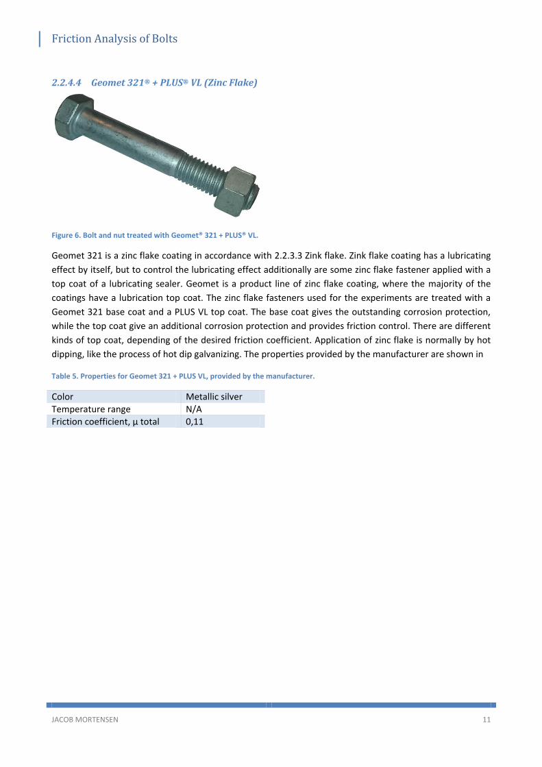
2.2.4.4 Geomet 321® + PLUS® VL (Zinc Flake)
Figure 6. Bolt and nut treated with Geomet® 321 + PLUS® VL.
Geomet 321 is a zinc flake coating in accordance with 2.2.3.3 Zink flake. Zink flake coating has a lubricating
effect by itself, but to control the lubricating effect additionally are some zinc flake fastener applied with a
top coat of a lubricating sealer. Geomet is a product line of zinc flake coating, where the majority of the
coatings have a lubrication top coat. The zinc flake fasteners used for the experiments are treated with a
Geomet 321 base coat and a PLUS VL top coat. The base coat gives the outstanding corrosion protection,
while the top coat give an additional corrosion protection and provides friction control. There are different
kinds of top coat, depending of the desired friction coefficient. Application of zinc flake is normally by hot
dipping, like the process of hot dip galvanizing. The properties provided by the manufacturer are shown in
Table 5. Properties for Geomet 321 + PLUS VL, provided by the manufacturer.
Color Metallic silver Temperature range N/A Friction coefficient, µ total 0,11

Friction Analysis of Bolts
JACOB MORTENSEN 12
3 Bolt connection The bolted joint is a good way to assemble to parts, in a way the can easily be reassembled again. The main
job for at bolted joint is to keep the clamped part together. To achieve this do the preload has to be of a
size that it can withstand different forces working on the bolted joint, preferably without reaching the yield
strength of the fastener. The following sections will describe different tightening technics, give an introduc-
tion to the forces acting on a bolted joint through force/displacement diagrams and show a method of cal-
culation the needed tightening torque.
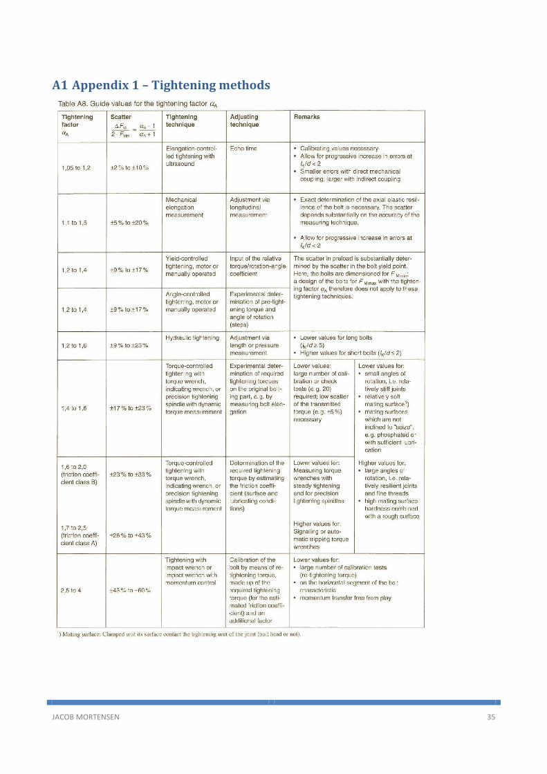
3.1 Tightening technique There are several ways to tighten a bolted joint. Most of the methods are shown in table from VDI 2230
that is to find in Appendix 1. The table do also describe the precision of the methods. The 8 method listed
in the table uses one or a combination of the following general tightening methods:
- Torque-controlled tightening
- Yield-controlled tightening
- Angle-controlled tightening
Furthermore are there three more general tightening methods that are not mentioned in VDI 2230:
- Bolt stretch method
- Heat tightening
- Use of tension indicating methods
These methods are not mentioned in the VDI 2230, since calculation of tightening torque and preload, are
very different for these method.
Torque-controlled tightening are the most widespread method, due to its cost-effective tools and easy
handling. This method uses tools that measures the torque transferred to the fastener, and then either
gives a signal or turns of when the desired torque is reached.
Angle-controlled tightening uses the theoretically relationship between the linear deformation of the bolt
over the pitch of the thread and the angle of rotation the bolt are tightened. This is done be tightening the
bolted joint enough to ensure full contact between the surfaces, and then rotate the bolt a calculated
amount of degrees to obtain the desired preload. The two methods (torque-controlled tightening and an-
gle-controlled tightening) can be combined, so the procedure is to tighten the fastener to eg. 75% of the
preload, and then use angle-controlled tightening to tighten to fastener to the desired preload. The combi-
nation of the methods eliminate some of the cons the individual method has.
Yield-controlled tightening uses a tool, which tightens the fastener until the fastener reaches the yields
point. This point is recognized by measuring the torque and the angle of rotation under the tightening pro-
cess. When the yield point is reached will the relationship between these two factors change drastically,
thereby revealing the yield point. This method eliminates the scatter from the variance in friction, but the
preload is with this method a result of the size and material of the fastener.
The precision of the different tightening methods vary widely, as the table in Appendix 1 shows. This means
that it is of high importance to choose the right tightening method for the job. Figure 7 shows a bolted joint
Friction Analysis of Bolts
JACOB MORTENSEN 13
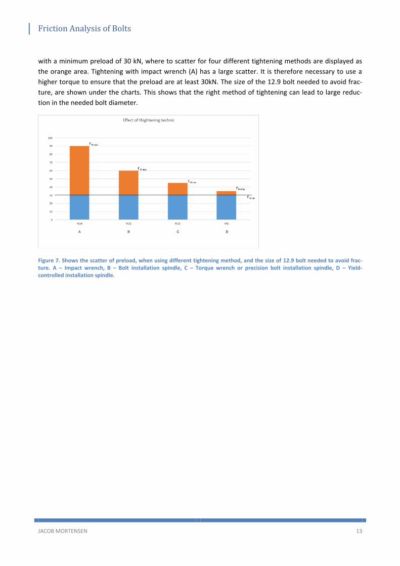
with a minimum preload of 30 kN, where to scatter for four different tightening methods are displayed as
the orange area. Tightening with impact wrench (A) has a large scatter. It is therefore necessary to use a
higher torque to ensure that the preload are at least 30kN. The size of the 12.9 bolt needed to avoid frac-
ture, are shown under the charts. This shows that the right method of tightening can lead to large reduc-
tion in the needed bolt diameter.
Figure 7. Shows the scatter of preload, when using different tightening method, and the size of 12.9 bolt needed to avoid frac-ture. A – Impact wrench, B – Bolt installation spindle, C – Torque wrench or precision bolt installation spindle, D – Yield-controlled installation spindle.

Friction Analysis of Bolts
JACOB MORTENSEN 14
3.2 Force/displacement description of bolts A force/displacement diagram is a good way to visualize the all the forces working on a bolted joint. A bolt-
ed joint are showed in three different states in Figure 8. Figure 8-1 shows the initial state of the preloaded
assembly where the preload Fm is not produced yet. Figure 8.2 shows the assembled state after the pre-
load is introduced. The last state shown in Figure 8.3 are the working state. Here are the bolted joint af-
fected by both the preload and a working load. In between the initial state and the assembled state are the
bolted joint tightened to introduce the preload Fm. The preload force are pushing the clamped parts togeth-
er, resulting in a clamp force FK at the interface. In the working state are the bolted joint introduced to an
axial working load FA that is acting on the clamped parts.
Figure 8. Preloaded bolted joint. 1. Initial state. 2. Assembled state. 3. Working state.
The forces acting on the bolted joint leads to chance in size of the clamped parts and the bolt. The preload
and the therefrom produced clamp force results in a compression ƒPM of the clamped parts, and an elonga-
tion ƒSM of the bolt. In the assembly state are the clamp force identical to the preload, giving:
𝐹𝑀 − 𝐹𝐾 = 0 ( 3-1 )
If the bolted joint is exposed to a working load, will this lead to an increase of the force acting on the bolt
FSA, resulting in an elongation of this ƒSA. This elongation will relieve the clamped parts with a corresponding
force FPA elongating the clamped parts with the same length ƒPA. The clamp force is therefore reduced by
the workload, while the preload is the same as in the assembled state. This gives us:
𝐹𝑀 − 𝐹𝐾 − 𝐹𝐴 = 0 ( 3-2 )

Friction Analysis of Bolts
JACOB MORTENSEN 15
These states can be visualized be using a force/displacement diagram. This is a diagram as shown on Figure
9-2. The figure shows the assembled state of a bolted joint, which is the state displayed on Figure 9-1. The
diagram has gathered the graph for the bolt and the plate in the same diagram to make it possible to com-
pare them. This is done by mirroring and displace the graph for the plate parts, since these parts are sub-
ject to compression instead of the elongation the bolt are subject to. The graphs shows that the elongation
and compression of the bolt and plate parts respectively, are linear in regard to the force the parts are ex-
posed to. It is furthermore possible to see that the bolted joint meets equation ( 3-1 ), since the preload
and the clamp force are of the same size.
Figure 9. Shows the assembled state of a bolted joint (1), and the corresponding force/displacement diagram (2).
The force/displacement diagram for the working state are shown on Figure 10. When the working load is
introduced will the load on the bolt part be increased, which shows in the diagram as the elongation of the
bolt graph. The diagram displays how the working load affects the clamp force and how the forces acting
on the bolt and plate part are changed. The diagram also visualizes how the change in length of the bolt
part and the plate part are identical, even though the load added to the bolt and relieved from the plate
parts can be quite dissimilar.
Figure 10. Shows the working state of a bolted joint (1), and the corresponding force/displacement diagram (2).

Friction Analysis of Bolts
JACOB MORTENSEN 16
Figure 11 shows a state where the work load is greater than the preload, resulting in a reduction of the
clamp force to zero. This means that the plate parts will separate and a gab will occur between them. This
is naturally not a desired, since the gab can result in failure.
Figure 11. Shows the gap state of a bolted joint (1), and the corresponding force/displacement diagram (2).

Friction Analysis of Bolts
JACOB MORTENSEN 17
3.3 Calculation of tightening torque Torque-controlled tightening is the most common way to tighten a bolted joint. To obtain the necessary
preload, do the corresponding tightening torque have to be calculated. The total tightening torque MA, that
is required to obtain the desired preload FM, consists of the thread torque MG and the head or nut torque
Mk.
𝑀𝐴 = 𝑀𝐺 +𝑀𝐾 ( 3-3 )
If there for the bolted joint are used fasteners that prevent loosening (self-locking nuts, serrated bearing
face bolt, etc.), are the overbolting moment Mü and the additional head moment MKZu added to the total
tightening torque.
The equation for the thread torque can be derived by looking at the relations between the clamping force
and the thread torques point of attack and direction. The thread torque are working at the pitch diameter
d2, with the helix angle of the thread ϕ in the perpendicular direction to the axis and the angle of friction ρ’
as a tangent to the axis.
𝑀𝐺 = 𝐹𝑀 ∙𝑑22tan(𝜑 + 𝜌′)
( 3-4 )
For metric thread are the pitch P and the flank angle α used:
tan(𝜑) =𝑃
(𝜋 ∙ 𝑑2)
( 3-5 )
tan(𝜌′) = 𝜇′𝐺 =𝜇𝐺
cos(𝛼2)
( 3-6 )
Both metric and unified fasteners has a flank angle α=60°, giving µ’G=1,155 µG. This can be used to simplifie
the equation.
tan(𝜑 + 𝜌′) ≈ tan(𝜑) + tan(𝜌′)
=𝑃
(𝜋∙𝑑2)+ 1,155𝜇𝐺
( 3-7 )

Friction Analysis of Bolts
JACOB MORTENSEN 18
Thus:
𝑀𝐺 = 𝐹𝑀(0,16 ∙ 𝑃 + 0,58 ∙ 𝑑2 ∙ 𝜇𝐺) ( 3-8 )
To derive the equation for the head/nut friction moment do the radius to the friction diameter need to be
known. This radius can be calculated by:
𝐷𝐾𝑚 =𝑑𝑤 + 𝐷𝐾𝑖
2
( 3-9 )
Where
𝐷𝐾𝑖 = max(𝐷𝑎, 𝑑ℎ𝑎, 𝑑ℎ , 𝑑𝑎) ( 3-10 )
The variable dw are the outside diameter of the bearing surface at the head or at the nut. Furthermore are
inside diameter of the bearing surface at the head or at the nut defined by which diameter is the largest of
the chamfer diameter of the nut Da, the chamfer diameter of the clamped parts dha, the hole diameter dh or
the inside diameter of the plane bearing head area da. The moment required to overcome the friction be-
tween the bearing surface and the head or nut, can then be calculated from the following equation:
𝑀𝐾 = 𝐹𝑀 ∙𝐷𝐾𝑚2
∙ 𝜇𝐾 ( 3-11 )
By combining the thread torque MG ( 3-8 ) and the head or nut friction moment MK ( 3-11 ), so they follows
the principle of equation ( 3-3 ), gives the equation for tightening torque. Here are the variables the desired
clamp force, the friction of the thread and the friction bearing surface between clamped parts and head or
nut.
𝑀𝐴 = 𝐹𝑀(0,16 ∙ 𝑃 + 0,58 ∙ 𝑑2 ∙ 𝜇𝐺+𝐷𝐾𝑚2
∙ 𝜇𝐾) ( 3-12 )
A table of the sizes used the metric threaded fasteners are to find in Appendix 3, while the table for an ap-
proximated friction coefficient are to find in Appendix 2.

Friction Analysis of Bolts
JACOB MORTENSEN 19
4 Experiments This chapter will describe the test setup, how the test where performed, the factors of influence on the test
and how these factors were controlled.
4.1 Test setup The experiments where performed in accordance with ISO 16047, on the test machine shown on Figure 12.
ISO 16047-“Fasteners – Torque/clamp force testing” are the international standard that specifies the condi-
tions for carrying out torque/clamp force testing. The test machine are built, so it meet the requirements
stated in ISO 16047. The test machine can be used to both torque/clamp force testing and a regular tensile
strength testing.
Figure 12. The full test setup. 1. In test state with the safety glass and doors closed. 2. Close-up of the whole setup.
Figure 12-2 is a close-up of the whole setup, where it is possible to see how all the different parts are con-
nected, that later in this section will be described individually. From the top and down does it consist of an
electrical motor with gearing, a torque meter, test bench, another torque meter and three load cells.

Friction Analysis of Bolts
JACOB MORTENSEN 20
Figure 13. Bauer BG50 4kW helical geared motor.1. seen from the front. 2. Seen from the side.
Figure 13 shown the electrical motor that tightens the fastener. There are for this test machine used a 4kW
Bauer BG50 helical geared motor, which with its output and gearing are powerful enough to be used to be
used with M24 and smaller. This motor can provide a stable RPM that is important for the experiments to
meet the requirements of ISO 16047.
Figure 14. The torque meter are marked with a red circle. A tool to turn the nut is mounted on the torque meter, while the green circle marks the tool to hold the head of the bolt.
There are on the electrical motor mounted a torque meter, which are the white box marked with a red
circle. The Torque meter can measure the torque the electrical motor supplies the bolted joint. Further-
more can the torque meter measure the RPM the fastener are tightened with. A tool to turn the nut is
mounted on the torque meter, and the counterpart for the head of the bolt are mounted underneath the
test bench.

Friction Analysis of Bolts
JACOB MORTENSEN 21
Figure 15. Underneath the table. The shaft in the middle has a torque meter mounted, which is the lighter grey part. The orange parts on the side are motors/gears for changing the height of the test bench.
Underneath the table are the second torque meter mounted in the shaft, as seen on Figure 15. This torque
meter is used to measure the thread torque, hence this is the only torque in the shaft. The picture also
shows the electrical motor and worm gear for changing the height of the test bench. The same motor and
worm gear are used to apply force, when the machine is used to tensile strength test.
Figure 16. Bottom of the test machine. In the middel are the shaft from the test bench. The three metal cylinders that is placed on the left, right and behind the shaft are the load cells.
At the very bottom are the shaft mounted on a plate, where three load cells also are mounted, as shown on
Figure 16. The combined load on these three load cells represents the preload of the fastener.

Friction Analysis of Bolts
JACOB MORTENSEN 22
The machine was last calibrated on 26/9-2013, less than two month before the experiments where per-
formed. The calibrating made sure that the machine meet the requirements described in ISO 16047. Re-
quirements like:
- Maximum ±2% deviation on the torque measurement
- Maximum ±2% deviation on the load cell measurement
- Maximum ±2% deviation on the angle measurement
- Tightening shall be carried out with constant speed
Additionally is it important that the stiffness of the testing machine, load cells and test fixture are constant
throughout the test. The test machine used for the experiments meets all these requirements, except the
stiffness of the testing machine that can be under dimensioned when testing fasteners that are larger then
M20 10.9 and M24 8.8.
Friction Analysis of Bolts
JACOB MORTENSEN 23
4.2 Factors of influence The following shows some of the factors that influence the tightening of a bolted joint. This section will
describe these factors and how they have been controlled in the experiments, if possible.
Table 6. Shows some of the factors that have influence on the tightening of a bolted joint.
4.2.1 Fastener
The design of the fastener has naturally a large influence, since this is the determining factor for the place-
ment and size of the contact areas. This factor is however not important in the experiments, since the fas-
teners used, all are with the same design and size.
Material, surface treatment and lubrication are all factors that the experiments covers. These are the fac-
tors that varies in the different experiments, in an effort to determine their influence.
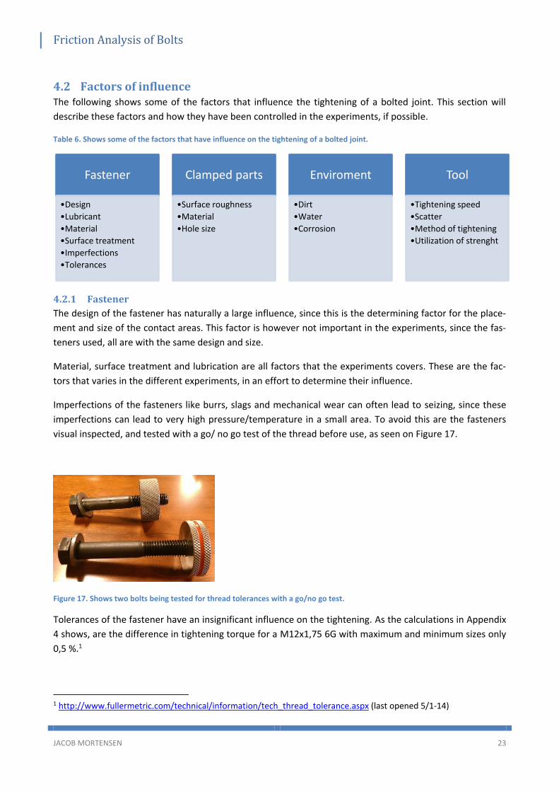
Imperfections of the fasteners like burrs, slags and mechanical wear can often lead to seizing, since these
imperfections can lead to very high pressure/temperature in a small area. To avoid this are the fasteners
visual inspected, and tested with a go/ no go test of the thread before use, as seen on Figure 17.
Figure 17. Shows two bolts being tested for thread tolerances with a go/no go test.
Tolerances of the fastener have an insignificant influence on the tightening. As the calculations in Appendix
4 shows, are the difference in tightening torque for a M12x1,75 6G with maximum and minimum sizes only
0,5 %.1
1 http://www.fullermetric.com/technical/information/tech_thread_tolerance.aspx (last opened 5/1-14)
Fastener
•Design
•Lubricant
•Material
•Surface treatment
•Imperfections
•Tolerances
Clamped parts
•Surface roughness
•Material
•Hole size
Enviroment
•Dirt
•Water
•Corrosion
Tool
•Tightening speed
•Scatter
•Method of tightening
•Utilization of strenght

Friction Analysis of Bolts
JACOB MORTENSEN 24
4.2.2 Clamped parts
The material and surface roughness influence the tightening of the bolted joint by the friction and the ten-
dency to seize. In the experiments are there used a washer of to minimize the influence of these factors.
There are used HV 200 steel washers for all fasteners of steel and HV 200 austenitic steel washer for the
austenitic steel fasteners. Every experiment where performed with at new washer, to secure even condi-
tions.
The hole size of the clamped parts does not affect the tightening in the experiments since the washer has a
smaller hole diameter than the clamped parts.
4.2.3 Environment
Dirt, water and corrosion are all factors that is relatively easy to remove in the test setup, but can be hard
to avoid in practice. These factors has the biggest influence on fasteners of smaller size. This is due to the
surface pressure that is produced in fasteners of larger size. Water will quickly vaporize when the pressure
builds, but can still be harmful since it can remove lubricant in some area, leaving the fastener unprotected.
Dirt like sand can have a large influence on small size fasteners, but not with larger sizes of fasteners and a
proper lubricant. The sand will be crushed by the large pressure, leaving the lubricants bearing surface be-
tween the bolt and nut.
4.2.4 Tool
As described earlier in the report do the method of tightening and the accompanying scatter have a great
influence on the utilization of the fastener. This is however not a concern in the perform experiments, since
the scatter of the tool used, maximum is ± 2%.
The speed of the tightening do however have quite an influence on the tightening. All the experiments will
be performed with a tightening speed of 10RPM, which is the minimum recommend speed in ISO 16047 for
at M12 fastener. Higher tightening speed raises the tendency for the fasteners to seize, especially for the
austenitic steel that already has a high tendency to seize.

Friction Analysis of Bolts
JACOB MORTENSEN 25
4.3 Test procedure All the test where performed with the same procedure, which featured the following steps:
1. Test bench is placed so the length between upper and lower parts fit the length of the bolt used.
The distance should be so the bolt are the nut height + 1-2 thread over the upper part of the test
bench.
2. All relevant data are entered in the computer.
3. Apply lubrication to the bolt and nut (if lubrication are tested). Or degrease the bolt and nut if a
clean surface is desired.
4. The bolt is mounted in the tool and placed in the test bench.
5. Place the nut on the bolt and tighten by hand.
6. Lower the electrical motor.
7. Start test on computer.
8. Tighten nut until the desired preload are reached.
9. Untighten the nut, raise the electrical motor and remove the nut and bolt from the test bench.
10. Clean the test bench if necessary.
11. Repeat 3-10 if more fasteners are tested in same series.
All test without lubricant are performed first to minimize lubricant on the test bench. A change in lubricant
includes are cleaning and degreasing of the test bench.

Friction Analysis of Bolts
JACOB MORTENSEN 26
5 Results This section will gather and compare all the measurements from the experiments. All the data from the
experiments are located in Appendix 5. The test report results are split on two sides. The first side contains
firstly the data entered in the test software on the computer, as shown on Figure 18. This is both to have
the values to make the calculations, but also to note which conditions the test with executed with. Under
misc. test data are the used lubricant and the proof load noted. The proof load are the load the nut shall
withstand, without deformation or fraction. This is used in the tests, in that way that the tightening is
stopped when the preload gets higher than the proof load.
Figure 18. Part of a test report. The value entered in the test software to define the test parameters.
Secondly are the on the first side of the test report a table with all the results from the test series. The
table contains the maximum preload reached, the corresponding tightening torque and the friction coeffi-
cient for the test. The friction coefficients are listed in total friction coefficient, head friction coefficient (µ1)
and thread friction coefficient (µ2). There are underneath the table with the test data a statistics evaluation
of the test series, with the average total friction coefficient and the standard deviation thereof.
Figure 19. To the left are the table with the test results and to the right are statistic evaluation of the test series.

Friction Analysis of Bolts
JACOB MORTENSEN 27
On the second side are three diagrams. The first diagram are a revolution/torque diagram, as shown on
Figure 20. This diagram are not very interesting for the experiments performed in this report.
Figure 20. Revolution/torque diagram from the test report.
The second diagram is a torque/preload diagram as shown on Figure 21. This diagram is interesting because
it visualizes the scatter of the test series. With a perfect test series, would all the line be on top of each
other. This would mean that all the fasteners are performing identical. Scatter is easily observed on this
diagram, hence the individual graphs then are spread apart. The gradient of the graph represents the total
friction of the bolted joint.
Figure 21. Torque/ preload diagram from the test report.
The last diagram are also a torque / preload diagram, but this has two graphs. The blue graph are for head
torque, while the red one are for thread torque.
Figure 22. Torque/ preload diagram where the torque is split in head torque (blue) and thread torque (red).
Friction Analysis of Bolts
JACOB MORTENSEN 28
5.1 Friction coefficients
5.1.1 Plain Fasteners
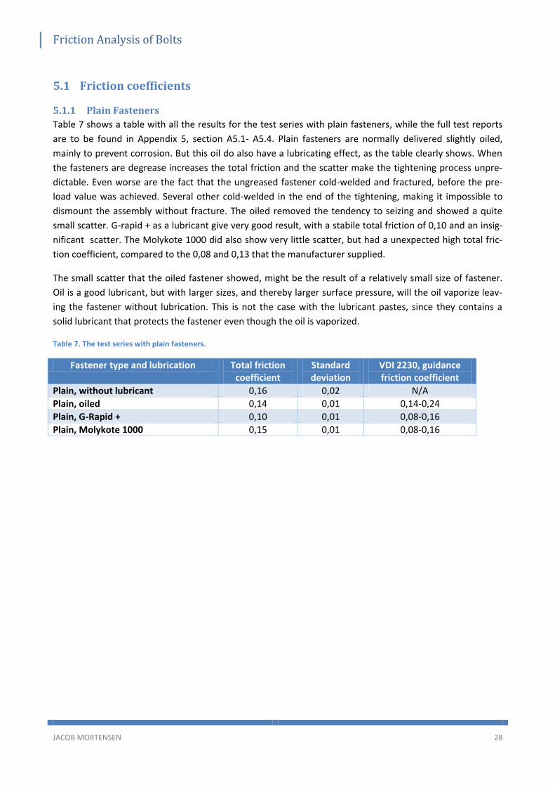
Table 7 shows a table with all the results for the test series with plain fasteners, while the full test reports
are to be found in Appendix 5, section A5.1- A5.4. Plain fasteners are normally delivered slightly oiled,
mainly to prevent corrosion. But this oil do also have a lubricating effect, as the table clearly shows. When
the fasteners are degrease increases the total friction and the scatter make the tightening process unpre-
dictable. Even worse are the fact that the ungreased fastener cold-welded and fractured, before the pre-
load value was achieved. Several other cold-welded in the end of the tightening, making it impossible to
dismount the assembly without fracture. The oiled removed the tendency to seizing and showed a quite
small scatter. G-rapid + as a lubricant give very good result, with a stabile total friction of 0,10 and an insig-
nificant scatter. The Molykote 1000 did also show very little scatter, but had a unexpected high total fric-
tion coefficient, compared to the 0,08 and 0,13 that the manufacturer supplied.
The small scatter that the oiled fastener showed, might be the result of a relatively small size of fastener.
Oil is a good lubricant, but with larger sizes, and thereby larger surface pressure, will the oil vaporize leav-
ing the fastener without lubrication. This is not the case with the lubricant pastes, since they contains a
solid lubricant that protects the fastener even though the oil is vaporized.
Table 7. The test series with plain fasteners.
Fastener type and lubrication Total friction coefficient
Standard deviation
VDI 2230, guidance friction coefficient
Plain, without lubricant 0,16 0,02 N/A
Plain, oiled 0,14 0,01 0,14-0,24
Plain, G-Rapid + 0,10 0,01 0,08-0,16
Plain, Molykote 1000 0,15 0,01 0,08-0,16

Friction Analysis of Bolts
JACOB MORTENSEN 29
5.1.2 Electrically galvanized fasteners (FZB)
The results of the test series with the electrically galvanized fasteners are listed in Table 8 and the full test
results are in Appendix 5, section A5.4 – A5-8. This type of fastener are in delivery state without any oil.
This is mainly due to the common use of this type of fastener. Electrically galvanized fasteners are rarely
used in bolted joints with a high preload. As the test results show are the fasteners also pretty hard to use
in the non-lubricated state. The total friction is high, and the scatter is very high, making it impossible to
control the tightening. The torque/preload diagram shows the large spread of friction coefficient, and that
the majority of the fasteners fracture before they reach the proof load. This is also the reason that it is
common to treat electrically galvanized fastener with a wax, if the preload has some kind of significance.
The Gleitmo 605 treatment shows a good total friction coefficient on 0,12, and a quite small scatter. The
solid lubricants are both very convincing in their use, with a friction coefficient as advertised and an almost
non-existent scatter.
Table 8. The test series with electrically galvanized fasteners.
Fastener type and lubrication Total friction coefficient
Standard deviation
VDI 2230, guidance friction coefficient
FZB, without lubricant 0,25 0,04 0,20-0,35
FZB, G-Rapid + 0,09 0,00 0,08-0,16
FZB, Molykote 1000 0,10 0,01 0,08-0,16
FZB, Gleitmo 605 0,12 0,01 0,08-0,16
5.1.3 Hot-dip galvanized fasteners (FZV)
Table 9 shows a table with all the results for the test series with hot-dip galvanized fasteners, while the full
test reports are to be found in Appendix 5, section A5.9- A5.12. The hop-dip galvanized bolt are in delivery
state without oil, while the nuts are delivered slightly oil. Unlike the plain fasteners are the oil mainly for
lubrication on hot-dip galvanized fasteners. Also in these tests are lubrication needed. The degreased fas-
teners have a hard time reaching the proof load and several fracture. Never the less do the degreased fas-
tener act a lot better, than VDI 2230 had predicted. The oil treatment of the nut are like the plain fasteners
enough to achieve a low friction coefficient and a surprisingly small scatter. The solid lubricant pastes do
also with hot-dip galvanized fasteners show a good and uniform tightening.
Table 9. The test series with hot-dip galvanized fasteners.
Fastener type and lubrication Total friction coefficient
Standard deviation
VDI 2230, guidance friction coefficient
FZV, without lubricant 0,16 0,03 0,20-0,35
FZV, oiled 0,12 0,01 N/A
FZV, G-Rapid + 0,11 0,01 0,08-0,16
FZV, Molykote 1000 0,12 0,01 0,08-0,16

Friction Analysis of Bolts
JACOB MORTENSEN 30
5.1.4 Austenitic stainless steel fasteners
The test series with austenitic stainless steel fasteners are shown in Table 10, and the full test reports are
attached in Appendix 5, section A5.13- A5.16. When performing the experiments with the austenitic steel
fasteners, are it obvious that they act a lot different than the steel fasteners. The friction coefficients are
much higher, and the tendency to seizing are very large. None of the non-lubricated fasteners that were
tested reached the proof load. The test results in Appendix 5, A5.15 clearly shows why. There friction coef-
ficient are so high, that the torque needed to build the desired preload are over 300Nm. This results in a
torsional fracture of the bolts. The Gleitmo 605 treated bolts all made the proof load, but the scatter is high
and the tightening very unpredictable. Some of the Gleitmo 605 treated fasteners did also get a plastically
deformation of the thread, making them hard to disassembly and unusable after removal. Even the solid
lubricant pastes are having a hard time holding the scatter at an acceptable level. Molykote 1000 do also
have a quite high friction coefficient with austenitic stainless steel.
Table 10. The test series with austenitic stainless steel fasteners.
Fastener type and lubrication Total friction coefficient
Standard deviation
VDI 2230, guidance friction coefficient
Austenitic steel, without lubricant 0,42 0,08 >0,30
Austenitic steel, G-Rapid + 0,11 0,02 0,08-0,16
Austenitic steel, Molykote 1000 0,17 0,02 0,08-0,16
Austenitic steel, Gleitmo 605 0,38 0,02 0,14-0,24
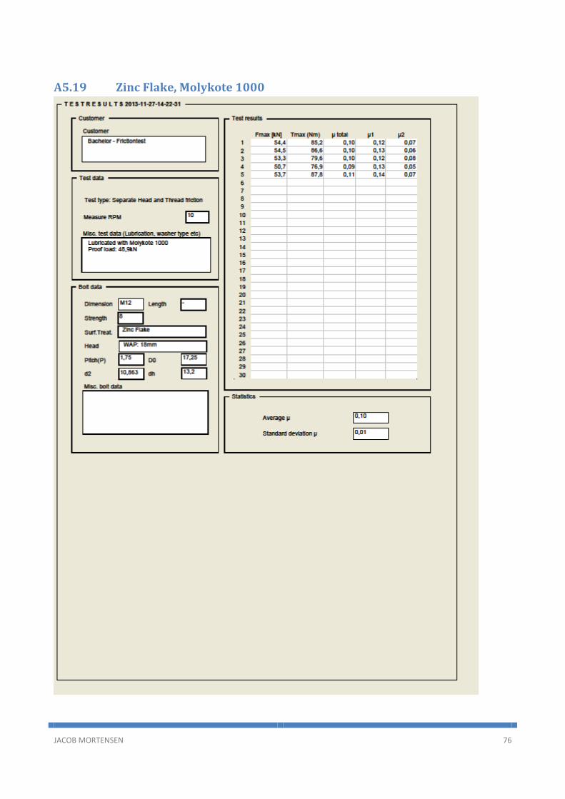
5.1.5 Zinc flake fasteners
The result of the Zinc flake fastener test series are shown in Table 11 and the full test results are to be
found in Appendix 5, section A5.17- A5.19. The Zinc flake fasteners are not oiled, but the fasteners used for
these test have a lubrication top coating. This results in very good and uniform tightening performance. The
friction coefficient are stable does not change even when using the solid lubricant pastes. The scatter are
extremely low with the fasteners that only are treated with the top coat. Applying extra lubricant in the
form of G-Rapid + or Molykote, only increases the scatter. The increase is however very small, and the scat-
ter is in a range, where the tightening is easy to control. For these experiments had it been more interest-
ing to use Zinc flake fasteners without the lubricating top coat.
Table 11. The test series with zinc flake fasteners.
Fastener type and lubrication Total friction coefficient
Standard deviation
VDI 2230, guidance friction coefficient
Zinc Flake, without lubricant 0,10 0,00 N/A
Zinc Flake, G-Rapid + 0,09 0,01 N/A
Zinc Flake, Molykote 1000 0,10 0,01 N/A

Friction Analysis of Bolts
JACOB MORTENSEN 31
5.2 Tensile strength test To ensure that the fasteners used for the experiment met the requirements in strength, were one of each
type of fastener tensile strength tested. The full test report are attached in Appendix 6. The proof load val-
ue for a M12 property class 8 nut are listed to be 74,2kN in ISO 898-2:2012, Table 4. The results of the ten-
sile strength test are listed in Table 12.
Table 12. Tensile strength test of the fasteners used for the experiments.
Fastener type Tensile strength test
Plain 78,8kN
Electrically galvanized 78,6kN
Hot-dip galvanized 74,2kN
Austenitic steel 82,5kN
Zinc flake 75,8kN
The tensile strength test of the fastener shows that all the tested fasteners meet the tensile strength re-
quirements.

Friction Analysis of Bolts
JACOB MORTENSEN 32
6 Conclusion The main conclusion to the test series, are that if bolted joint shall be tightened under controlled condi-
tions, are some kind of lubricant a necessity. For the M12 size fastener, that have been used to the experi-
ments in this report, are oil generally sufficient to achieve a uniform tightening and an acceptable level of
scatter. Oil is however known to be insufficient when the surface pressure get higher, than it did in the
experiments conducted in connection with this report.
Molykote 1000 is a widely used lubricant for fasteners. The tests has shown that Molykote 1000 performs
very well for a many different types of surface treatments and materials. The scatter were significantly re-
duced by introducing Molykote 1000. The friction coefficient do however vary when using Molykote 1000
on different surface treatment and material. This is not a problem since the variation are small, and the
scatter are of the range it is.
If a small variation is desired in the friction coefficient between different materials and surface treatments,
are the G-Rapid + solid lubricant paste an option. This paste has shown very good results with every type of
surface it has been tested on in this test. Even the austenitic stainless steel, where Molykote 1000 had a
slight increase of friction coefficient, were no problem for the G-Rapid +. G-Rapid + had overall a friction
coefficient of 0,10 and a highly controllable scatter.
Gleitmo 605 where tested on austenitic steel- and electrically galvanized steel fastener, which are the
common types of fasteners to combine with this friction controlling treatment. This treatment showed
good result with the electrically galvanized fastener, but were doubtful for use with the austenitic stainless
steel fastener.
Using plain fasteners for a bolted joint, does not set strict requirements for lubricants in the sizes that have
been used in this project. The plain fasteners have a quite predictable tightening, as long as they are lubri-
cated. Even non-lubricated plain fasteners can be tightened without major problems. They do however not
have the same predictability that the lubricated version has.
Electrically galvanized fasteners are a bit trickier to work with. This type of fastener needs some kind of
lubrication, if the tightening shall be just a little uniform. Electrically galvanized fasteners can be treated
with a wax like Gleitmo 605, to achieve an easy and fairly controllable tightening. If a higher controllability
is needed can the solid lubricant pastes be used.
Hot-dip galvanized fasteners are like the plain fasteners quite controllable as long as they have some kind
of lubrication. It is not recommended to use this kind of fastener without any lubrication if the predictabil-
ity of the tightening is important.
The austenitic steel fasteners how been quite interesting in this test. The requirements of a good lubricant
agent is unquestionably present when using this material. The austenitic steel has a high tendency to seize.
The main purpose of the lubricant agent is to keep this from happening. The experiments shows that it is
not possible to tighten a non-lubricated austenitic fastener to the proof load. Gleitmo 605 made it possible
to achieve the proof load, but the friction coefficient was still, way too high. The solid lubricant paste did
however show some decent result. Especially G-rapid + had the ability to keep a low friction coefficient,
minimize seizing and making the tightening predictable.

Friction Analysis of Bolts
JACOB MORTENSEN 33
The zinc flake fasters tested in this report, were delivered with a friction controlling top coat. This lead to a
fastener with a low friction coefficient and scatter no matter the lubricant were used. This experiment had
been more useful if the fasteners had been without the lubricating top coat.

Friction Analysis of Bolts
JACOB MORTENSEN 34
Appendix
Contents
A1 Appendix 1 – Tightening methods ....................................................................................................... 35
A2 Appendix 2 – Friction coefficients ....................................................................................................... 36
A3 Appendix 3 – Design values for metric fasteners ................................................................................ 37
A4 Appendix 4 – Calculation of tolerance influence ................................................................................. 39
A5 Appendix 5 – Test data ........................................................................................................................ 40
A5.1 Plain without oil ............................................................................................................................... 40
A5.2 Plain oiled ........................................................................................................................................ 42
A5.3 Plain, oiled with G-Rapid + .............................................................................................................. 44
A5.4 Plain, oiled with Molykote 1000 ...................................................................................................... 46
A5.5 FZB, no lubrication ........................................................................................................................... 48
A5.6 FZB, with G-Rapid + ......................................................................................................................... 50
A5.7 FZB, with Molykote 1000 ................................................................................................................. 52
A5.8 FZB, with Gleitmo 605 ..................................................................................................................... 54
A5.9 FZV, no lubrication ........................................................................................................................... 56
A5.10 FZV, oiled ..................................................................................................................................... 58
A5.11 FZV, G-rapid + .............................................................................................................................. 60
A5.12 FZV, Molykote 1000 ..................................................................................................................... 62
A5.13 A4-80, no lubrication ................................................................................................................... 64
A5.14 A4-80, G-rapid + ........................................................................................................................... 66
A5.15 A4-80, Molykote 1000 ................................................................................................................. 68
A5.16 A4-80, Gleitmo 605 ...................................................................................................................... 70
A5.17 Zinc Flake, no lubrication ............................................................................................................. 72
A5.18 Zinc Flake, G-Rapid + ................................................................................................................... 74
A5.19 Zinc Flake, Molykote 1000 ........................................................................................................... 76
A6 Appendix 6 – Tensile strength test ...................................................................................................... 78
JACOB MORTENSEN 35
A1 Appendix 1 – Tightening methods

JACOB MORTENSEN 36
A2 Appendix 2 – Friction coefficients

JACOB MORTENSEN 37
A3 Appendix 3 – Design values for metric fasteners

JACOB MORTENSEN 38

JACOB MORTENSEN 39
A4 Appendix 4 – Calculation of tolerance influence
FM 54kN
P 1.75mm
d2minustolerance 10.679mm
d2plustolerance 10.829mm
DKm19 12
2mm
G 0.12
K 0.12
Ma FM 0.16 P 0.58 d2minustolerance GDKm
2K
Ma 54 kN 0.7432584mm 0.93mm 0.28mm( ) 105.476N m
Ma FM 0.16 P 0.58 d2plustolerance GDKm
2K
Ma 54 kN 0.7536984mm 0.93mm 0.28mm( ) 106.04N m
106.04 105.476( )
105.476100 0.535

JACOB MORTENSEN 40
A5 Appendix 5 – Test data
A5.1 Plain without oil

JACOB MORTENSEN 41

JACOB MORTENSEN 42
A5.2 Plain oiled

JACOB MORTENSEN 43

JACOB MORTENSEN 44
A5.3 Plain, oiled with G-Rapid +

JACOB MORTENSEN 45

JACOB MORTENSEN 46
A5.4 Plain, oiled with Molykote 1000

JACOB MORTENSEN 47

JACOB MORTENSEN 48
A5.5 FZB, no lubrication

JACOB MORTENSEN 49

JACOB MORTENSEN 50
A5.6 FZB, with G-Rapid +

JACOB MORTENSEN 51

JACOB MORTENSEN 52
A5.7 FZB, with Molykote 1000

JACOB MORTENSEN 53

JACOB MORTENSEN 54
A5.8 FZB, with Gleitmo 605

JACOB MORTENSEN 55

JACOB MORTENSEN 56
A5.9 FZV, no lubrication

JACOB MORTENSEN 57

JACOB MORTENSEN 58
A5.10 FZV, oiled

JACOB MORTENSEN 59

JACOB MORTENSEN 60
A5.11 FZV, G-rapid +

JACOB MORTENSEN 61

JACOB MORTENSEN 62
A5.12 FZV, Molykote 1000

JACOB MORTENSEN 63

JACOB MORTENSEN 64
A5.13 A4-80, no lubrication

JACOB MORTENSEN 65

JACOB MORTENSEN 66
A5.14 A4-80, G-rapid +

JACOB MORTENSEN 67

JACOB MORTENSEN 68
A5.15 A4-80, Molykote 1000

JACOB MORTENSEN 69

JACOB MORTENSEN 70
A5.16 A4-80, Gleitmo 605

JACOB MORTENSEN 71

JACOB MORTENSEN 72
A5.17 Zinc Flake, no lubrication

JACOB MORTENSEN 73

JACOB MORTENSEN 74
A5.18 Zinc Flake, G-Rapid +

JACOB MORTENSEN 75
JACOB MORTENSEN 76
A5.19 Zinc Flake, Molykote 1000

JACOB MORTENSEN 77

JACOB MORTENSEN 78
A6 Appendix 6 – Tensile strength test
6


