IntroductionOn-line motion control of human power augmentation
exoskeleton systems is still a big challenge specially for the applications in complicated and dynamic terrains. By this we mean indoors mission conditions with frequent changing between flat terrain walking and stairs ascent or vice versa. Human-exoskeleton systems designed for constraining human movements to allow people to operate more easily or more efficiently in a variety of situations, required consideration of efficient control and economical issues. Here we mean these systems to be available for the public must have an efficient and available control strategy so can have further application developments. The efficiency of motion control strategy will be measured in according to the some performance features, such as interaction force and tracking error. In human-powered exoskeleton systems the real-time adaptive motion control is yet complex process. This complexity is proportional to the system’s maneuverability.
The fully autonomous human power augmentation exoskeleton system must be controlled to behave and interact as human being, with the sensory system, communication media, muscles, joints, and main controller. These parts are in loop for standing alone human as well as for human power exoskeleton system (Human-in-the-Loop), with interactive behaviour for different situations and transitions [1]. The main feature needs to pay attention of such system with discrete time events (sensory feedback signals) according to human intentions and continuous time during system’s navigation is response time. The human navigation process is unique without time delay and can’t be achieved 100% on human power augmentation exoskeleton system, still researches are conducted to achieve high performance efficiency [2]. Looking at the human body from an engineering point of view, we notice that it has many types of inputs and outputs. The human Central Nervous System (CNS) is the part of the nervous system consisting of the brain and spinal cord and represented by the main controller in our
system. Because the human body is a very complex structure and and just consider the lower limbs, there are endogenous or internal signals that can be perceived by the senses to control lower limbs motion. The main outputs of the lower limbs from the feedback signals is the movements and maneuvers. Information primary travels from the sensors to the main controller to identify and decide the next coming maneuver, these signals are the reflection of current human intentions.
The aim of this paper is to provide an overview of the most effective motion control strategies for the lower limb human power augmentation exoskeleton systems. Lower limbs Exoskeletons, which have a wide range of possible applications include physical support and facilitating labor-intensiveness by decreasing the load action on the operator. The physical support field of above application form three main groups of powered lower-limb devices: rehabilitative, assistive, and empowering devices. The paper is organized as follows: Section 4 shows the description and integration of the famous human-exoskeleton system, and the our lab exoskeleton HUALEX. We describe motion control strategies in Section 5. Section 6 shows the performance efficiency of the studied strategies on a single DoF exoskeleton platform. Finally, conclusions and some perspective on future uses and further development of these strategies drawn in section 7.
*Corresponding author: Abusabah IA Ahmed, Center for Robotics, School ofAutomation, University of Electronic Science and Technology of China, Chengdu,China. Tel: 8615928716860; E-mail: [email protected]
Received October 03, 2016; Accepted November 09, 2016; Published November 11, 2016
Citation: Ahmed AIA, Cheng H, Lin X, Omer M, Atieno JM (2016) Survey of On-line Control Strategies of Human-Powered Augmentation Exoskeleton Systems. Adv Robot Autom 5: 158. doi: 10.4172/2168-9695.1000158
AbstractOn-line gait control in human-powered exoskeleton systems is still rich research field and represents a step
towards fully autonomous, safe and intelligent indoor and outdoor navigation. It is still a big challenge to develop a control strategy which makes the exoskeleton supply an efficient tracking for pilot intended trajectories on-line. Considering the number of degrees of freedom the lower limb exoskeletons are simpler to design, compared to upper limb. The comparison between lower limb and upper limb is useless when consider the control issues, because of the differences in missions and applications. Based on the literature, we aim to give an overview about control strategies of some famous lower limb human power exoskeleton systems. In the state of the art, different control strategies and approaches for different types of lower limb exoskeletons will be compared consider the efficiency and economic issues. Exact estimation of needed joints torques to execute human intended motions on-line with efficient performance, low cost and reliable way is the main goal of studied system’s control strategies. We have study different control strategies used for wide known human power augmentation exoskeletons and compare between them in graphs and tables.
Survey of On-line Control Strategies of Human-Powered Augmentation Exoskeleton SystemsAhmed AIA1*, Cheng H1, Lin X1, Omer M2 and Atieno JM3
1Center for Robotics, School of Automation, University of Electronic Science and Technology of China, 611731 Chengdu, China2School of Automation, University of Electronic Science and Technology of China3School of Electronic Engineering, University of Electronic Science and Technology of China, 611731 Chengdu, China
Citation: Ahmed AIA, Cheng H, Lin X, Omer M, Atieno JM (2016) Survey of On-line Control Strategies of Human-Powered Augmentation Exoskeleton Systems. Adv Robot Autom 5: 158. doi: 10.4172/2168-9695.1000158
Page 2 of 8
Volume 5 • Issue 3 • 1000158Adv Robot Autom, an open access journalISSN: 2168-9695
Typical Lower-Limb Exoskeleton SystemsLegged locomotion has many advantages comparing to wheels, it’s
efficient performance on rough and unpredictable terrain [3]. Wheels are useful for flat surfaces applications and simple to control but they have worse performance on rough and unpredictable terrain navigation. In the opposite Legs can adapt to a wide variety of environments, such as rough terrains and staircases, which are impassable by wheeled vehicles [4,5]. In other words legs are maneuverable and effective for wide range of applications. Parallel-limb exoskeleton designed for load transfer to the ground in parallel with the human lower limb. It features the DoFs of the human to be compatible with lower leg dynamics. The exoskeleton robots can keep the balance on its own, while shadow the human wearer intended motion during navigation [6].
Many different exoskeleton robots have been developed from the early 1960s [7]. They can be categorized in several ways: by power source, by actuators, by structure, by function, and by application. Lower limb exoskeletons have been built for augmenting human performance, assisting with disabilities, studying human physiology and reactivate motor deficiencies [8-10]. For purpose of discussion, exoskeletons are divided into two categories here. The first type of exoskeleton is one used to help gait disorder persons or aged people to walk. The second type of exoskeleton is used to help people walking who have to travel long distances by feet with heavy loads. For power augmentation exoskeletons, the power of the robot joints must be generated with active joints such as electric motors or hydraulic cylinders. Power Augmentation exoskeletons refers to exoskeletons that can give neurologically intact, healthy human capabilities above and beyond the normal ones. This has usually been focused on increasing strength and enhancing endurance for difficult conditions applications. Direct interaction of power augmentation exoskeleton with the human neuromotor system during locomotion requires adequate design of the components, both the bio-mechanical and functional aspects for safety issues. The on-line motion of such systems control is challenge especially in outdoors applications, with un-known terrain’s condition. The length of the thigh and the shank links of such exoskeletons are adjustable by a mechanism of two telescopic bars that are fixed in different positions by screws to fit different wearer’s height in limited range.
A. Berkeley lower extremity exoskeleton (BLEEX)
Berkeley Lower Extremity Exoskeleton (BLEEX) designed aroundprimarily supporting a large load in the form of a backpack, this limited it’s direct interaction with the human body [11-13]. BLEEX was funded by the Defence Advanced Research Project Agency (DARPA) at the University of California, Berkley, and beginning in the year 2000 [8]. It has been designed for the specific task of allowing the human wearer to bear a large load on their back. The device is composed of three parts, the two powered robotic legs, the power and computing unit, and a backpack frame as shown in Figure 1. BLEEX is the first load carrying autonomous exoskeleton [14]. With an anthropomorphic design, BLEEX has a left and right three-segment leg, being analogous to the human thigh, shank and foot. Each leg has seven DoFs: hip flexion/extension and abduction/adduction, knee flexion/extension and ankle dorsi/plantar flexion are active. BLEEX provides the operator with load-carrying capability and endurance through versatile legged locomotion. Possible applications include helping soldiers, disaster relief workers, wildfire fighters and other emergency personnel to carry major loads without the strain typically associated with demanding labor [3].
B. Human universal load carrier (HULC)
From the public information, we know that Exohiker is very goodat variety of locomotion and robustness, and can almost follow any action of the human body, or even intentionally sudden step, squat, creeping and other movements. The construction of ExoHiker was completed in February 2005. After finishing the Exohiker study, the team packaged all technology to the Lockheed Martin, who carried out technical transformation of military engineering. In 2009, the system was renamed Human Universal Load Carrier (HULC) and released. On the other hand, it had some upper limb function and was expected to form the Army soldiers’ equipment in a few years. Since then, the progress of the research went into secrecy. Exohiker (or HULC) has been the most outstanding one of all lower extremity exoskeleton systems, although there is still a certain gap to the ideal in the weight and working time etc. But the appearance of Exohiker (or HULC) makes the exoskeleton really be out of the laboratory and people see the possibility of its practical application.
Dismounted fighters often carry heavy combat loads that increase the stress on the body leading to potential injuries. With a HULC exoskeleton, these heavy loads are transferred to the ground through powered titanium legs without loss of mobility. The HULC is a completely un-tethered, hydraulic powered anthropomorphic exoskeleton that provides users with the ability to carry loads of up to 200 pounds for extended periods of time and over all terrains. Its flexible design allows for deep squats, crawls and upper-body lifting. An onboard micro-computer ensures the exoskeleton moves in concert with the individual. The HULC’s modularity allows for major components to be swapped out in the field. Additionally, its unique power-saving design allows the user to operate on battery power for extended missions. When battery power is low, the HULC system continues to support the loads and does not restrict mobility. HULC can also support a maximum load, with or without power. Lockheed Martin is also exploring exoskeleton designs for industrial use and a wider variety of military mission specific applications [15,16].
HULC specifications are as follows:
- Total weight without batteries is 53 lb.
- The power is Lithium polymer batteries.
- Electronics are Flexible, expandable electronics architecture forfuture applications, custom single-board microelectronics housed in a sealed enclosure and heat sinks on actuators.
- Hydraulic system is efficient low-flow, high pressure hydraulicsystem uses standard hydraulic fluid.
The HULC exoskeleton operates on lithium polymer batteries.
Figure 1: The most famous lower limbs human power augmentation exoskeletons.
Citation: Ahmed AIA, Cheng H, Lin X, Omer M, Atieno JM (2016) Survey of On-line Control Strategies of Human-Powered Augmentation Exoskeleton Systems. Adv Robot Autom 5: 158. doi: 10.4172/2168-9695.1000158
Page 3 of 8
Volume 5 • Issue 3 • 1000158Adv Robot Autom, an open access journalISSN: 2168-9695
The power-saving feature enables the system to support maximum load even when the battery power is low. When equipped with an extended mission power supply with recharge capability, would enable dismounted Soldiers on these missions to carry fewer batteries.
C. Hybrid assistive limb (HAL)
Sankai et al. began developing the exoskeleton Hybrid Assistive Limb (HAL) in the mid of 1990s [17]. Their first prototype had active joints with single DoF at the hips and the knees, as well as a passive joint at the ankles. This model was followed by other versions of HAL-3 as shown in Figure 1. It is one of the most closely integrated with the human body. However, there are many improvements that need to be addressed in order to help user (for rehabilitation or force augmentation) learn to walk [18,19]. These include specific size, physical connections, powered control, software, and communication needs. The links that make up the lower body of the exoskeleton will need to be redesigned to allow for the inclusion of additional motors, and the electric motors may need to be replaced with hydraulics all together to be able to perform with new and additional software requirements. HAL-3 system is composed of three main parts skeleton and actuator, controller, and sensor [20]. Exoskeletal frame consists of a four-link, three-joint mechanism with the links corresponding to the hip the thigh, the lower thigh and the foot, and the joints corresponding to the hip, the knee and the ankle joints of the human body. The actuators of HAL-3 provide assist torque for knee and hip joints. Each actuator has a DC-motor with harmonic drive to generate the assist torques at each joint. The total weight of the skeleton system with the actuators is about 15 Kg [21]. HAL-3 controlled by Cybernic Control System which consists of Cybernic Voluntary Control (CVC) system and Cybernic Autonomous Control (CAC) System [22]. When a person attempts to move their body, nerve signals are sent from the brain to the muscles through the motor neurons, moving the musculoskeletal system. When this happens, small bio signals can be detected on the surface of the skin. The HAL suit registers these signals through a sensor attached to the skin of the wearer. Based on the signals obtained, the power unit moves the joint to support and amplify the wearer’s motion. The HAL suit possesses a cybernic control system consisting of both a user-activated voluntary control system known as CVC and a "robotic autonomous control system" known as CAC for automatic motion support.
HAL can be used even if no bio-electrical signals are detected, due to problems, say, in the central nervous system or the muscles. The Japanese-built, wearable, HAL exoskeleton, for example, offers improved endurance and strength for users, but is not mind-controlled. Instead of brain waves, HAL picks up EMG signals, the electrical pulses generated by the muscles and uses these to send commands to the exoskeleton. It also partially relies on the users existing mobility and balance to operate.
Meanwhile, Berkeley Bionics in the US has developed an EMG-based "medical exoskeleton" that enables people with reduced mobility and strength to walk upright. However, it requires a supporting device to keep users balanced.
The latest version of HAL has remained brain-controlled but evolved to a full body robot suit that protects against heavy radiation without feeling the weight of the suit. Eventually it could be used by workers dismantling the crippled Fukushima nuclear plant. The new type of HAL is on display today at the Japan Robot Week exhibition in Tokyo. It will be used by workers at nuclear disaster sites and will be field tested at Fukushima, where a tsunami in March 2011 smashed into the power plant, sparking meltdowns that forced the evacuation of a huge area of north-eastern Japan [22].
HAL uses electrical signals sent to the muscles from the brain to anticipate the wearer’s movement. HAL’s ability to anticipate movement allows it to move fractions of a second before the wearer, providing seamless interaction between human and robot [23].
D. Human power augmentation lower exoskeleton (HUALEX)
The Human power Augmentation Lower Exoskeleton (HUALEX) was demonstrated at the Centre for Robotic, School of Automation at University of Electronic Science and Technology of China. HUALEX has an an ergonomic design, robust and lightweight equipment for load carrier [24]. As shown in Figure 1, HUALEX has total four active joints to provide torques, which is activated by DC servo motors. The ankle joints of HUALEX is designed as an energy-storage mechanism which can store energy in stance phase and deliver in swing phase during walking. Besides the joints and rigid links, many compliant connections at waist, thighs, shanks and feet are provided for semi-rigid connecting HUALEX to the wearer. HUALEX system designed as lower limbs human power augmentation exoskeleton, in the hip structure has two DoFs performing functions of flexion/extension actuated by Maxon DC motors, two non-actuated DoFs abduction/adduction. At the knee joint, there is one DoF performing flexion/extension actuated by Maxon DC motors. At the ankle joint, there is one DoF performing dorsiflexion/planter flexion and another one at the metatarsophalangeal joint for flexion/extension, both are non-actuated. Thus, there are only four actuated DoFs in total in our system using Maxon DC motors attached with a harmonic drive gear because the flexion/extension DoFs of hip and knee play an important role during normal walking and its energy [24].
HUALEX control schemes are based on compliance method that relied on the measurement of interaction force resulted from the wearer intention to change gait mode or gait speed [25]. The learning approach of the relationship between physical human-exoskeleton interaction and dynamic factors [26,27] allows efficient application of Admittance Control (AC). Ordinary AC [28,29] can’t be applied for maneuverable human-powered augmentation exoskeleton systems (Figure 1).
Motion Control StrategyThe human provides an intelligent control system for the
exoskeleton, while the exoskeleton actuators provide most of the strength necessary for walking [30]. The control algorithms ensure that the exoskeleton moves in concert with the wearer depending on interaction force between them [31-33]. In this paper we address a distinctive control strategies for above mentioned exoskeleton systems and the implementation with a given system to show their performance efficiency. A model-based Control system [34] is one of the exoskeleton control system categories. According to the model used, the control strategy for the exoskeleton can be divided into two types: the dynamic model and the muscle model based control. The dynamic model can be obtained through the mathematical model, the system identification and the artificial intelligent method. Beside model-based control system other control system suitable for human power augmentation exoskeleton control are Hierarchy based Control System and Physical parameters based control system. The utilized and control system must meet the needed develop on the next step such as the assist as needed, the user’s intention detection, the safety and the stability to give better performance.
E. Sensitivity amplification control (SAC)
Sensitivity Amplification Control (SAC) algorithm was first
Citation: Ahmed AIA, Cheng H, Lin X, Omer M, Atieno JM (2016) Survey of On-line Control Strategies of Human-Powered Augmentation Exoskeleton Systems. Adv Robot Autom 5: 158. doi: 10.4172/2168-9695.1000158
Page 4 of 8
Volume 5 • Issue 3 • 1000158Adv Robot Autom, an open access journalISSN: 2168-9695
proposed in the augmentation applications of Berkeley Lower Extremity Exoskeleton (BLEEX). The SAC algorithm is widely used in human augmentation applications since it just need the information from the exoskeleton robot, so that the complexity of exoskeleton system can be reduced greatly. BLEEX control methodology SAC, efficient control way to shadow human motion but so expensive and resource consumer (hardware and software) [13].
Racine proposed a method named virtual joint torque control, this method also be called SAC [8], and apply it for BLEEX control. SAC needs no direct measurements from the pilot or from the human-machine interface (e.g. no force sensors between the them); instead, the controller estimates, based on measurements from the exoskeleton suits only, how to move so the pilot feels very little force. This control scheme, which has never before been applied to any robotic system, is an effective method of generating locomotion when the contact location between the pilot and the exoskeleton is unknown and unpredictable.
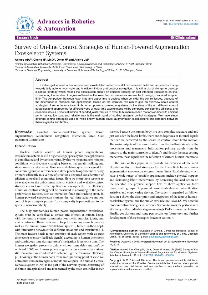
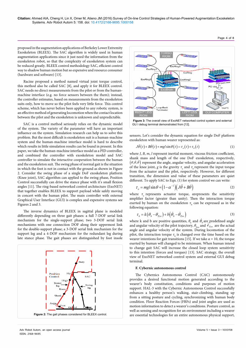
SAC is a control method seriously relies on the dynamic model of the system. The variety of the parameter will have an important influence on the system. Simulation research can help us to solve this problem. But the most difficult is exoskeleton suit is a human-machine system and the human-machine interface model is hard to describe which results in little simulation results can be found in present. In this paper, we take the human-machine interface model as a PID controller, and combined the controller with exoskeleton model and SAC controller to simulate the interactive cooperation between the human and the exoskeleton suit. The swing phase of normal gait is the situation in which the foot is not in contact with the ground as shown in Figure 2. Consider the swing phase of a single DoF exoskeleton platform (Knee joint), SAC algorithm can applied to the swing phase, Position Control successfully can drive the stance phase with it’s small flexion angles [11]. The ring-based networked control architecture (ExoNET) that together enables BLEEX to support payload while safely moving in concert with the human pilot. The main controller with external Graphical User Interface (GUI) is complex and expensive systems see Figures 2 and 3.
The inverse dynamics of BLEEX in sagittal plane is modeled differently depending on three gait phases: a full 7-DOF serial link mechanism for the single-support phase; two 3-DOF serial link mechanisms with one connection DOF along their uppermost link for the double-support phase; a 3-DOF serial link mechanism for the support leg and a 4-DOF mechanism for the redundant leg during late stance phase. The gait phases are distinguished by foot insole
sensors. Let’s consider the dynamic equation for single DoF platform exoskeleton with human wearer represented as:
( ) ( ) ( ) ( ) ( )sin a hJ t B t mgl t t tθ θ θ τ τ+ + = + (1)
where J, B, m, l represent inertial moment, viscous friction coefficient, shank mass and length of the one DoF exoskeleton, respectively, ( ), , θ θ θ represent the angle, angular velocity, and angular acceleration of the knee joint, g is the gravity τa and τh represent the input torque from the actuator and the pilot, respectively. However, for different transition, the dimension and value of these parameters are quiet different. To apply SAC to Eqn. (1) for system control we can write:
( )( )1sin 1a mgl J Bτ θ α θ θ−= + − + (2)
where τa represents actuator torque, αrepresents the sensitivity amplifier factor (greater than unity). Then the interaction torque exerted by human on the exoskeleton τh can be expressed as in the following equation:
( ) ( )h h Exo h Exok bτ θ θ θ θ= − + − (3)
where k and b are positive quantities, θh and hθ are predefined angle and angular velocity of the pilot trajectory, θExo and Exoè are the actual angle and angular velocity of the system. During locomotion of the pilot, the interaction torque τh is changed over the time based on the wearer intentions for gait transitions [15]. If we take α = 10, the torque exerted by human will changed to be minimum. When human intend to change gait SAC will increase the closed loop system sensitivity to this intention (forces and torques) [13]. SAC strategy, the overall view of ExoNET networked control system and external GUI debug terminal.
F. Cybernic autonomous control
The Cybernics Autonomous Control (CAC) autonomously provides a desired functional motion generated according to the wearer’s body constitution, conditions and purposes of motion support. HAL-3 with the Cybernic Autonomous Control successfully enhances a healthy person’s walking, stair-climbing, standing up from a sitting posture and cycling, synchronizing with human body condition. Floor Reaction Forces (FRFs) and joint angles are used as motion information to detect a wearer’s conditions. Posture control, as well as sensing and recognition for an environment including a wearer are essential technologies for an entire autonomous physical support, Figure 2: The gait phases considered for BLEEX control.
Figure 3: The overall view of ExoNET networked control system and external GU I debug terminal demonstrated from [12].
Citation: Ahmed AIA, Cheng H, Lin X, Omer M, Atieno JM (2016) Survey of On-line Control Strategies of Human-Powered Augmentation Exoskeleton Systems. Adv Robot Autom 5: 158. doi: 10.4172/2168-9695.1000158
Page 5 of 8
Volume 5 • Issue 3 • 1000158Adv Robot Autom, an open access journalISSN: 2168-9695
but they remain to be solved as shown in Figure 4. Human Intention Estimator (HIE) is used for wearer’s intentions detection to use for robot motion control. Instead of the bioelectrical signals used for the control of the conventional HAL, the FRF is used for an intention estimation of the wearer who can control his weight balance using two canes with his hands. HAL estimates which leg supports a wearer’s weight, when a wearer begins to swing a right or left leg and when wearer wants to stop walking. This control consists of the PD control using reference walking patterns based on healthy person’s walk, in the swing phase and the constant-value control in the landing and support phase. Figure 4 shows a block diagram for this tracking control and phase synchronization. The HIE located in the upper-left part in the Figure 4 has the FRF as inputs for the estimation algorithms described below. Three blocks under the HIE are a library of the reference patterns in the swing phase and the reference values in the landing and support phase. The HIE allocates these references to two legs during walking. There are six ordinary PD control blocks on the right side of the HIE and the library. The upper three blocks are controllers for the right leg and the lower ones are for the left leg. The reference walking patterns, should be adjusted according to the wearer’s intentions, for example a walking cycle and amplitude of each joint trajectory in swinging leg, while the stance phase is position controlled. The command torque for a single DoF τ is calculated by:
( ) ( )ˆref refK C K Cτ θ θ θ θ= − + − (4)
where θ is the actual wearer’s joint angle, θ is angular velocity, respectively. In addition, θre f and refè are the reference joint angle and the reference angular velocity, respectively. On the other hand, K is the feedback gain of the joint angle error, and K̂ is the feedback gain of the joint angular velocity error. The different feedback gains are used in the swing, landing or support phase independently by adopting this control architecture. In addition, C is the gain to the reference joint angle and angular velocity.
G. Variable admittance control (VAC)
The modified Admittance Control AC performs well on the gait transitions and walking speed changing cases, the overshoot and undershoots resulted on the measured interaction force have been treated for smooth transition [35-37]. The regulated admittance parameters help to find an appropriate input command (trajectory reference change). It is evident that this input depends on wearer desired flexion angle and desired admittance parameters [38-40]. To improve such AC to pretty handle the uncertainties in dynamics model when human intend to change gait dynamic parameters estimation technique called variable admittance controller (VAC) was introduced. The investigated VAC algorithm attempts to minimize the interaction
force during whole navigation process of the coupled human-exoskeleton system, i.e. better tracking performance [41,42].
Force impulse and instantaneous end-effector oscillations are perfect system inputs to estimate VAC parameters [43]. The Cartesian space intended position depends on the stair height in this case can be transformed to the joint space as the mean value of the difference between the desired and the actual trajectories. This difference ∆θ(t) will be used to modify the input trajectory to get to the optimized trajectory:
( ) ( ) ( )*h ht t tθ θ θ= + ∆ (5)
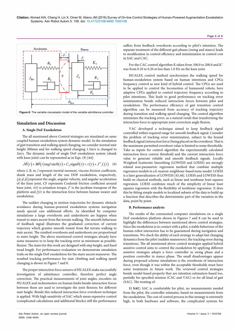
The block diagram of VAC is shown in Figure 5 and the variable viscoelastic model of proposed VAC is drawn in Figure 6.
The dynamic process of input trajectory correction needs dynamic viscoelastic admittance parameters while keeping inertia constant:
0
0
dyn
dyn
K KB B
δ
η
=
= (6)
where K0 and B0 represent the initial stiffness and viscous friction coefficient of OAC, depends on the current gait type as estimated in section III. The main goal of proposed VAC scheme is to achieve smooth trajectory tracking during and after gait transitions in other words is to minimize the tracking error when human intend to change gait type. We investigate a relation between VAC parameters and interaction force for accurate and perfect human trajectory tracking even when sudden change in current trajectory happens. The dynamic stiffness and viscous are obtained on-line for smooth gait transitions. The linearity of the relation Eqn. (7) is experimentally proved for acceptable range of interaction force, this range is variable depends on human-exoskeleton system function.
( ) ( )( ) ( ) ( )( ) ( ) ( )( ) ( ) ( )TC h Exo C h Exo C h Exo iJ t t B t t K t t J t f tθ θ θ θ θ θ− + − + − = (7)
Experimentally we estimate the dynamic viscoelastic model parameters from collected data applying recursive least square estimator (RLSE). The considered model for the estimation of dynamic viscoelastic parameters is:
( ) ( ) ( )0 0 iB t K t tη θ δ θ τ∆ + ∆ = (8)
The initial value of unknown parameters vector [ ]0 0TK Bδ η are
[ ] [ ]1 1T Tδ η = , While 0 0 T
K B are variable through navigation process depend on the current gait (Figures 5and 6).
Figure 4: The main block diagram for HAL-3 tracking control demonstrated from [17]. Figure 5: The proposed block diagram for variable admittance control scheme.
Citation: Ahmed AIA, Cheng H, Lin X, Omer M, Atieno JM (2016) Survey of On-line Control Strategies of Human-Powered Augmentation Exoskeleton Systems. Adv Robot Autom 5: 158. doi: 10.4172/2168-9695.1000158
Page 6 of 8
Volume 5 • Issue 3 • 1000158Adv Robot Autom, an open access journalISSN: 2168-9695
suffers from feedback overshoots according to pilot’s intention. The separate treatment of the different gait phases (swing and stance) leads to modification in control efficiency and minimization in control cost in SAC and CAC.
For the CAC control algorithm K taken from 100.0 to 200.0 and Kˆ was from 0.10 to 0.20 at less than 1.0 Hz on the knee joint.
HUALEX control method synchronizes the walking speed for human-exoskeleton system based on human intentions and CPGs frequency control as new kind of hybrid control. The CPGs are used to be applied to control the locomotion of humanoid robots, here adaptive CPGs applied to control trajectory frequency according to pilot intentions. This leads to good performance on tracking error minimization beside reduced interaction forces between pilot and exoskeleton. The performance efficiency of gait transition control algorithm can be measured from accuracy of tracking trajectory during transition and walking speed changing. The control algorithm minimizes the tracking error, as a natural result that transforming the interaction force to appropriate joint correction angle flexion.
VAC developed a technique aimed to keep feedback signal controlled within required range for smooth feedback signal. Consider the problem of tracking error minimization, subject to the bound feedback signal (interaction force) being placed on the overshoot. That is the maximum permitted overshoot value is limited to some thresholds. Take as inputs for control algorithm the experimentally calculated interaction force convex threshold and the current interaction force value to generate reliable and smooth feedback signals. Locally Weighted Scattersite Smoothing (LOWESS and LOESS) are strongly related non-parametric regression method that combine multiple regression models in a k-nearest-neighbour-based meta-model. LOESS is a later generalization of LOWESS [45,46]. LOESS and LOWESS thus build on classical methods, such as linear and nonlinear least squares regression. LOESS combines much of the simplicity of linear least squares regression with the flexibility of nonlinear regression. It does this by fitting simple models to localized subsets of the data to build up a function that describes the deterministic part of the variation in the data, point by point.
B. Performance analysis
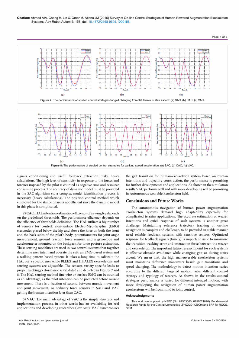
The results of the commented computer simulations on a single DoF exoskeleton platform shown in Figures 7 and 8 can be used to highlight the differences between mentioned above control strategies. Since the exoskeleton is in contact with a pilot, a stable behaviour of the human-robot interaction has to be guaranteed during navigation and transitions. We check the ability of each strategy to adapt fast changing dynamics from the pilot (sudden maneuvers), the tracking error during transitions. The all mentioned above control strategies applied hybrid assistive control aims to control the exoskeleton by applying different assistive strategies adopts a force controller in swing phase and a position controller in stance phase. The small disadvantages appear during proposed scheme simulations is the overshoots of interaction force, even though it was within the acceptable thresholds must have some treatments in future work. The reviewed control strategies beside model-based property they are intention estimation-based too, partially for specified mission (CAC and VAC) or for all kind of gait (SAC). The treating of:
1) SAC: SAC is comfortable for pilot, no measurements needed from the pilot, the controller estimates, based on measurements from the exoskeleton. The cost of control process in this strategy is extremely high, in both hardware and software, the complicated systems for
Simulation and DiscussionA. Single DoF Exoskeleton
The all mentioned above Control strategies are simulated on same coupled human-exoskeleton system dynamic model. In the simulation of gait transition and walking speed changing, we consider normal stair height 200mm and for walking speed changing 1.5m/s is changed to 2m/s. The dynamic model of single DoF exoskeleton system (shank with knee joint) can be represented as in Eqn. (9) [44]:
( ) ( ) ( ) ( ) ( ) ( )isin sign TFJ t B t mgl t C t t J f tθ θ θ τ+ θ + = + (9)
where J, B, m, l represent inertial moment, viscous friction coefficient, shank mass and length of the one DOF exoskeleton, respectively, ( ), , θ θ θ represent the angle, angular velocity, and angular acceleration of the knee joint, CF represents Coulomb friction coefficient around knee joint, τ(t) is actuation torque, JT is the jacobian transpose of the platform and fi(t) is the interaction force between human wearer and exoskeleton.
The sudden changing in motion trajectories for dynamic obstacle avoidance during human-powered exoskeleton systems navigation needs special care additional efforts. As identified by computer simulations a large overshoots and undershoots are happen when transit to stairs ascent from flat terrain walking. The smooth behaviour of feedback signal illustrates the graduated correction of current trajectory which grantee smooth transit from flat terrain walking to stair ascent. The resulted overshoots and undershoots are proportional to stairs height. The above mentioned control strategies already have some measures to to keep the tracking error as minimum as possible. flexion. The stairs for this work are designed with step height, and fixed tread length. For performance evaluation we demonstrate simulation trails on the single DoF exoskeleton for the stairs ascent maneuver. The resulted tracking performance for stair climbing and walking speed changing is shown in Figure 7 and 8.
The proper interaction force sensors of HUALEX make successfully investigation of admittance controller, therefore perfect angle correction. The practical measurements of joint angles, encoders on HUALEX and inclinometers on human limbs beside interaction forces between them are used to investigate the joint flexions for different stair height. Beside this reduced interaction force overshoot technique is applied. With high sensitivity of SAC which mean expensive control (complicated calculations and additional blocks) still the performance
Figure 6: The variable viscoelastic model of the variable admittance controller.
Citation: Ahmed AIA, Cheng H, Lin X, Omer M, Atieno JM (2016) Survey of On-line Control Strategies of Human-Powered Augmentation Exoskeleton Systems. Adv Robot Autom 5: 158. doi: 10.4172/2168-9695.1000158
Page 7 of 8
Volume 5 • Issue 3 • 1000158Adv Robot Autom, an open access journalISSN: 2168-9695
signals conditioning and useful feedback extraction make heavy calculations. The high level of sensitivity in response to the forces and torques imposed by the pilot is counted as negative time and resource consuming process. The accuracy of dynamic model must be provided in the SAC algorithm so, a complex model identification process is necessary (heavy calculations). The position control method which employed for the stance phase is not efficient since the dynamic model in this phase is complicated.
2) CAC: HAL intention estimation efficiency of a swing leg depends on the predefined thresholds, The performance efficiency depends on the efficiency of thresholds definition. The HAL utilizes a big number of sensors for control: skin-surface Electro-Myo-Graphic (EMG) electrodes placed below the hip and above the knee on both the front and the back sides of the pilot’s body, potentiometers for joint angle measurement, ground reaction force sensors, and a gyroscope and accelerometer mounted on the backpack for torso posture estimation. These sensing modalities are used in two control systems that together determine user intent and operate the suit: an EMG-based system and a walking-pattern-based system. It takes a long time to calibrate the HAL for a specific user while BLEEX and HUALEX exoskeletons and sensing systems are adjustable. The sensors variety specific leads to proper tracking performance as validated and depicted in Figures 7 and 8. The HAL sensing method fine wire or surface EMG can be counted as an advantage, as the pilot intention can be predicted before muscle movement. There is a fraction of second between muscle movement and joint movement, so ordinary force sensors in SAC and VAC getting the human intention later than CAC.
3) VAC: The main advantage of VAC is the simple structure and implementation process, in other words has an availability for real applications and developing researches (low cost). VAC synchronizes
the gait transition for human-exoskeleton system based on human intentions and trajectory construction, the performance is promising for further developments and applications. As shown in the simulation results VAC performs well and with more developing will be promising in Autonomous wearable Exoskeleton field.
Conclusions and Future WorksThe autonomous navigation of human power augmentation
exoskeleton systems demand high adaptability especially for complicated terrains applications. The accurate estimation of wearer intentions and quick response of such systems is another great challenge. Maintaining reference trajectory tracking of on-line navigation is complex and challenge, to be provided in stable manner need reliable feedback systems with sensitive sensors. Optimized response for feedback signals (timely) is important issue to minimize the transition tracking error and interaction force between the wearer and exoskeleton. The important future research point for such systems is effective obstacle avoidance while changing gait or during stairs ascent. We mean that, the high maneuverable exoskeleton systems must maintains difference maneuvers beside gait transitions and speed changing. The methodology to detect motion intention varies according to the different targeted motion tasks, different control strategy and typology of wearers. As shown in the results control strategies performance is varied for different intended motion, with more developing the navigation of human power augmentation exoskeletons will be from mind to joint control.
Acknowledgments
This work was support by NSFC (No. 61503060, 6157021026), Fundamental Research Funds for the Central Universities (ZYGX2014Z009) and SRF for ROCS, SEM.
Figure 7: The performance of studied control strategies for gait changing from flat terrain to stair ascent: (a) SAC; (b) CAC; (c) VAC.
Figure 8: The performance of studied control strategies for walking speed acceleration: (a) SAC; (b) CAC; (c) VAC.
Citation: Ahmed AIA, Cheng H, Lin X, Omer M, Atieno JM (2016) Survey of On-line Control Strategies of Human-Powered Augmentation Exoskeleton Systems. Adv Robot Autom 5: 158. doi: 10.4172/2168-9695.1000158
Page 8 of 8
Volume 5 • Issue 3 • 1000158Adv Robot Autom, an open access journalISSN: 2168-9695
References
1. Schirner G, Erdogmous D, Chowdhurt K, Padir T (2013) The future of human-in-the-loop cyber-physical systems. Computer 46: 36-45.
2. Winter DA (2009) Biomechanics and motor control of human movement,(4thedn) New Jersey: John Wiley and Sensor Inc.
3. Zoss A, Kazerooni H (2006) Design of an electrically actuated lower extremityexoskeleton. Advanced Robotics 20: 967-988.
4. Andriacchi TP, Galante JO, Fermier RW (1982) The Influence of Total Knee-replacement Design on Walking and Stair Climbing. The Journal of Bone andJoint Surgery 64: 1328-1335.
5. Amirudin AN, Parasuraman S, AhmedKhan MKA, Elamvazuthi I (2014)Biomechanics of Hip, Knee and Ankle joint loading during ascent and descent walking. International Conference on Medical and Rehabilitation Robotics andInstrumentation 42: 336-344.
6. Tran HT, Cheng H (2014) Learning the Relation of Physical Interaction toDynamic Factors during Human-Exoskeleton Collaboration. IEEE International Conference on Multiple Fusion and Information Integration, Beijing.
7. Mosher RS (1967) Handyman to Hardiman. Society of Automation Engineering (SAE) International.pp: 1-10.
8. Racine JLC (2003) Control of a Lower Extremity Exoskeleton for HumanPerformance Amplification.
9. Kawamoto H, Lee S, Kanbe S, Sankai Y (2003) Power assist method for HAL-3 using EMG-based feedback controller. IEEE International Conference onSystems, Man and Cybernetics, pp: 1648-1653.
10. Huang R, Cheng H, Chen Q, Tran HT, Lin X (2015) Interactive Learning forSensitivity Factors of a Human-powered Augmentation Lower Exoskeleton.IEEE/RSJ International Conference on Intelligent Robots and Systems, pp:6409-6415.
11. Kazerooni H, Steger R, Huang L (2006) Hybrid Control of the Berkeley LowerExtremity Exoskeleton (BLEEX). International Journal of Robotics Research25: 561-573.
12. Kazerooni H, Chu A, Steger R (2007) That which does not stabilize, will onlymake us stronger. The International Journal of Robotics Research 26: 75-89.
13. Kazerooni H, Racine JL, Huang L, Steger R (2005) On the Control of theBerkeley Lower Extremity Exoskeleton (BLEEX). International Conference ofRobotics and Automation, pp: 4353-4360.
14. Zoss A, Kazerooni H, Chu A (2005) On the Mechanical Design of the Berkeley Lower Extremity Exoskeleton (BLEEX). International Conference on IntelligentRobots and Systems, pp: 3132-3139.
15. Ghan J, Steger R, Kazerooni H (2006) Control and system identification for the berkeley lower extremity exoskeleton. Advanced Robotics 20: 989-1014.
17. Kawamoto H, Sankai Y (2005) Power assist method based on phase sequence and muscle force condition for HAL. Advanced Robotics 19: 717-734.
18. Lee S, Sankai Y (2002) Power assist control for walking aid with HAL-basedon EMG and impedance adjustment around knee joint. IEEE/RSJ International Conference on Intelligent Robots and Systems (IROS 2002), pp: 1499-1504.
19. Okamura J, Tanaka H, Sankai Y (1999) EMG-based prototype poweredassistive system for walking aid. Asian Symposium on Industrial Automationand Robotics (ASIAR’99), pp: 229-234.
20. Lee S, Sankai Y (2005) Virtual Impedance Adjustment in Unconstrained Motion for Exoskeletal Robot Assisting Lower Limb. Advanced Robotics 19: 773-795.
21. Suzuki K, Kawamura Y, Hayashi T, Sakurai T, Hasegawa Y et al. (2005)Intention-Based Walking Support for Paraplegia Patients with Robot Suit HAL.IEEE International Conference on Systems, Man and Cybernetics, pp: 2707-2027.
22. Japan Robot Week (2016) International Robot Exhibition (iREX)
23. Kawamoto H, Sankai Y (2005) Power assist method based on phase sequence and muscle force condition for HAL. Advanced Robotics 19: 717-734.
24. Ka M, Cheng H, Toan TH, Jing Q (2015) Minimizing Human- ExoskeletonInteraction Force Using Compensation for Dynamic Un- certainty Error withAdaptive RBF Network. Journal of Intelligent and Robotic Systems, pp: 1-21.
25. Tran HT, Cheng H, Duong MK, Zheng H (2014) Fuuzy-based ImpedanceRegulation for Control of the Coupled Human-Exoskeleton System. IEEEInternational Conference on Robotics and Biomimetics, pp: 986-992.
26. Tran HT, Cheng H, Lin X, Huang R (2014) The Relationship between PhysicalHuman-Exoskeleton Interaction and Dynamic Factors: Using a LearningApproach for Control Applications. Science China Information Science 57: 12.
28. Augugliaro F, DeAndrea R (2013) Admittance Control for Physical Human-Quadrocopter Interaction. European Control Conference, pp: 1805-1810.
29. Oda M, Zhu C, Suzuki M, Luo X, Watanabe H, et al. (2010) Admittance Based Control of Wheelchair Typed Omnidirectional Robot for Walking Support andPower Assistance. 19th IEEE International Symposium on Robot and HumanInteractive Communication, pp: 159-164.
30. Astrom KJ, Wittenmark B (1995) Adaptive control (2ndedn) Addison Wesley,Reading.
31. Hassan M, Kadone H, Suzuki K, Sankai Y (2014) Wearable Gait Measurement System with an Instrumented Cane for Exoskeleton Control. Sensors 11:1705-1722.
32. De Rossi SMM, Lenzi T, Vitiello N, Donati M, Persichetti A, et al. (2011) Development of an in-shoe pressure-sensitive device for gait analysis.Engineering in Medicine and Biology Society, EMBC, Annual InternationalConference of the IEEE, pp: 5637-5640.
33. Liu T, Inoue Y, Shibata K (2010) A Wearable Ground Reaction Force SensorSystem and Its Application to the Measurement of Extrinsic Gait Variability. Sensors 10: 10240-10255.
35. Crea S, Donati M, De Rossi SMM, Oddo CM, Vitiello N (2014) Wireless Flexible Sensorized Insole for Gait Analysis. Sensors 14: 1073-1093.
36. Hoover CD, Fulk GD, Fite KB (2013) Stair Ascent With a Powered Transfemoral Prosthesis Under Direct Myoelectric Control. IEEE/ASME Transactionon Mechatronics 18: 1191-1200.
37. Riener R, Rabuffetti M, Frigo C (2002) Stair Ascent and Descent at DifferentInclinations. Gait and Posture 15: 32-44.
38. Hogan N (1984) Impedance Control: An Approach to Manipulation. AmericanControl Conference, pp: 304-313.
39. Tonietti G, Schiavi R, Bicchi A (2005) Design and Control of a Variable Stiffness Actuator for Safe and Fast Physical Human-Robot Interaction. InternationalConference on Robotics and Automation, pp: 526-531.
40. Miller LM, Rosen J (2010) Comparison of Multi-Sensor Admittance Controlin Joint Space and Task Space for a Seven Degree of Freedom Upper LimbExoskeleton. Proceedings of the 3rd IEEE RAS and EMBS InternationalConference on Biomedical Robotics and Biomechatronics, pp: 70-75.
41. Okunev V, Nierhoff T, Hirche S (2012) Human-preference-based Control Design: Adaptive Robot Admittance Control for Physical Human- RobotInteraction. The 21st IEEE International Symposium on Robot and HumanInteractive Communication, pp: 443-448.
42. Carmichael MG, Liu D (2013) Admittance Control Scheme for ImplementingModel-based Assistance-As-Needed on a Robot. 35th Annual InternationalConference of the IEEE EMBS, pp: 870- 873.
43. Colgate JE, Ollinger GA, Peshkin MA, Goswami A (2007) A 1-DOF AssistiveExoskeleton with Virtual Negative Damping: Effects on the Kinematic Response of the Lower Limbs. IEEE/RSJ International Conference on Intelligent Robotsand Systems, pp: 1938-1944.
44. Lee BK, Lee HD, Lee JY, Shin K, Han JS (2012) Development of DynamicModel-based Controller for Upper Limb Exoskeleton Robot. 2012 IEEEInternational Conference on Robotics and Automation, pp: 3173-3178.
45. Laboratory NB (1988) Anthropometry and mass distribution for humananalogues. Naval Biodynanlics Laboratory.
46. Fox J (2002) Nonparametric Simple Regression: Smoothing Scatterplots.Smoothing Scatterplots. Thousand Oaks, CA.