21
Diaphragm Pump Series N N3 KPE, N3 KP18 N5 KPE, N5 KP18 N9 KPE, N9 KP18 Instruction Manual Version 1.01.01

Diaphragm Pump Series N
N3 KPE, N3 KP18 N5 KPE, N5 KP18 N9 KPE, N9 KP18 Instruction Manual Version 1.01.01
2 N3..,N5..,N9.. | 1.01.01 www.mc-techgroup.com
Dear customer, Thank you for buying our product. In this instruction manual you will find all necessary information about this M&C product. The information in the instruction manual is fast and easy to find, so you can start using your M&C product right after you have read the manual. If you have any question regarding the product or the application, please don’t hesitate to contact M&C or your M&C authorized distributor. You will find all the addresses in the appendix of this manu-al. For additional information about our products and our company, please go to M&C’s website www.mc-techgroup.com. There you will find the data sheets and manuals of all our products in Ger-man and English.
This Operating Manual does not claim completeness and may be subject to technical modifications. © 10/2019 M&C TechGroup Germany GmbH. Reproduction of this document or its content is not allowed without permission from M&C. Version: 1.01.01
www.mc-techgroup.com N3..,N5..,N9.. | 1.01.01 3
List of Contents 1 General information ............................................................................................................. 4 2 Declaration of conformity .................................................................................................... 4 3 Safety instructions ............................................................................................................... 5 4 Warranty ................................................................................................................................ 5 5 Used terms and signal indications ..................................................................................... 6 6 Introduction .......................................................................................................................... 7 7 Application ............................................................................................................................ 7
7.1 Ambient conditions .............................................................................................................. 7 7.2 Safety instructions ............................................................................................................... 8
8 Technical data ...................................................................................................................... 9 9 Receipt of goods and storage ............................................................................................. 9 10 Installation instructions ..................................................................................................... 10
10.1 Mechanical installation ...................................................................................................... 10 10.2 Electrical installation .......................................................................................................... 12 10.3 Pneumatic ......................................................................................................................... 13
11 Supply line connections .................................................................................................... 13 11.1 Hose-/Tube connections.................................................................................................... 13
12 Starting ................................................................................................................................ 14 13 Closing down ...................................................................................................................... 14 14 Maintenance........................................................................................................................ 14
14.1 Removing the pump head type N 3/5/9 KPE/KP18 ............................................................ 15 14.2 Changing the diaphragm type N 3/5/9 KPE/KP18 ............................................................. 16 14.3 Changing the valve plates type N 3/5/9 KPE/KP18 ........................................................... 16 14.4 Refitting the pump heads type N 3/5/9 KPE/KP18 ............................................................. 16 14.5 Cleaning ............................................................................................................................ 16
15 Trouble shooting ................................................................................................................ 18 16 Spare parts list ................................................................................................................... 19 17 Appendix ............................................................................................................................. 20
List of Figures Figure 1 Dimensions (mm) N3/5 KPE ......................................................................................... 10 Figure 2 Dimensions (mm) N9 KPE ............................................................................................ 11 Figure 3 Dimensions (mm) N3/5 KP18 ........................................................................................ 11 Figure 4 Dimensions (mm) N9 KP18 ........................................................................................... 11 Figure 5 Electrical connections .................................................................................................... 12 Figure 6 Sectional drawing N3/5 KPE .......................................................................................... 15 Figure 7 Sectional drawing N9 PE ............................................................................................... 15 Figure 8 Pump capacity N3/5 KPE/KP18 ..................................................................................... 21 Figure 9 Pump capacity N9 KPE/KP18 ........................................................................................ 21

4 N3..,N5..,N9.. | 1.01.01 www.mc-techgroup.com
Head Office M&C TechGroup Germany GmbH Rehhecke 79 40885 Ratingen Germany Telephone: 02102 / 935 - 0 Fax: 02102 / 935 - 111 E - mail: [email protected] www.mc-techgroup.com 1 GENERAL INFORMATION
The product described in this manual has been built and tested in our production facility. All M&C products are packed to be shipped safely. To ensure the safe operation and to maintain the safe condition, all instructions and regulations stated in this manual need to be followed. This manual includes all information regarding proper transportation, storage, installation, operation and mainte-nance of this product by qualified personnel. Follow all instructions and warnings closely. Read this manual carefully before commissioning and operating the device. If you have any questions regarding the product or the application, please don’t hesitate to contact M&C or your M&C authorized distributor. 2 DECLARATION OF CONFORMITY
CE - Certification The product described in this operating manual complies with the following EU directives: EMV-Instruction The requirements of the EU directive 2014/30/EU “Electromagnetic compatibility“ are met. Low Voltage Directive The requirement of the EU directive 2014/35/EU “Low Voltage Directive“ are met. The compliance with this EU directive has been examined according to DIN EN 61010. Declaration of conformity The EU Declaration of conformity can be downloaded from the M&C homepage or directly requested from M&C.

www.mc-techgroup.com N3..,N5..,N9.. | 1.01.01 5
3 SAFETY INSTRUCTIONS
Please take care of the following basic safety procedures when mounting, starting up or oper-ating this equipment: Read this operating manual before starting up and use of the equipment. The information and warn-ings given in this operating manual must be heeded. Any work on electrical equipment is only to be carried out by trained specialists as per the regulations currently in force. Attention must be paid to the requirements of VDE 0100 (IEC 364) when setting high-power electrical units with nominal voltages of up to 1000 V, together with the associated standards and stipulations. Check the details on the type plate to ensure that the equipment is connected to the correct mains voltage. Protection against touching dangerously high electrical voltages: Before opening the equipment, it must be switched off and hold no voltages. This also applies to any external control circuits that are connected. The device is only to be used within the permitted range of temperatures and pressures. Check that the location is weather-protected. It should not be subject to either direct rain or moisture. The pumps type N3/5/9.. must not be used in hazardous areas. Installation, maintenance, monitoring and any repairs may only be done by authorized personnel with respect to the relevant stipulations. 4 WARRANTY
If the equipment fails, please contact M&C directly or else go through your M&C authorised dealer. We offer a one year warranty as of the day of delivery as per our normal terms and conditions of sale, and assuming technically correct operation of the unit. Consumables are hereby excluded. The terms of the warranty cover repair at the factory at no cost or the replacement at no cost of the equipment free ex user location. Reshipments must be send in a sufficient and proper protective packaging.

6 N3..,N5..,N9.. | 1.01.01 www.mc-techgroup.com
5 USED TERMS AND SIGNAL INDICATIONS
DANGER!
This means that death, severe physical injuries and/or important material damages will occur in case the respective safety measures are not fulfilled.
W A R N I N G !
This means that death, severe physical injuries and/or important material damages may occur in case the respective safety measures are not fulfilled.
CARE!
This means that minor physical injuries may occur in case the respective safety measures are not fulfilled.
C A R E ! Without the warning triangle means that a material damage may occur in case the respective safety measures are not met.
A T T E N T I O N ! This means that an unintentional situation or an unintentional status
may occur in case the respective note is not respected.
NOTE!
These are important information about the product or parts of the operating manual which require user’s attention.
SKILLED STAFF These are persons with necessary qualification who are familiar with installation, use and maintenance of the product.
High voltages! Protect yourself and others against damages which might be caused by high voltages.
Corrosive! These substances destroy living tissue and equipment upon con-tact. Do not breathe vapors; avoid contact with skin and eyes.
Wear safety glasses! Protect your eyes while working with chemicals or sharp objects. Wear safety glasses to avoid getting something in your eyes.
Wear protective clothes! Working with chemicals, sharp objects or extremely high tempera-tures requires wearing protective clothes.

www.mc-techgroup.com N3..,N5..,N9.. | 1.01.01 7
6 INTRODUCTION
The compact diaphragm pumps type N3/5/9 are suitable for sampling air, gases and vapours in a temperature range between + 5 °C (41 °F) and + 40 °C (104 °F). The construction and the pump capacity are adapted to the requirements of the gas analysis technique. 7 APPLICATION
The sampling evacuation and compression of the diaphragm sample pump series N3/5/9 is 100 % oil-free. The operation is gas-tight and maintenance-free. The noise level of the pump without housing is less than 55 dB(A).(pneumatically connected).
Partnumber Type Material Pump head Diaphragm Valve Sealing 02 P 3351 N 3 KPE PVDF PTFE-beschichtet Viton Viton 02 P 3006 N 3 KP18 02 P 3355 N 5 KPE 02 P 3007 N 5 KP18 02 P 3360 N 9 KPE 02 P 3008 N 9 KP18
Material abbreviations according to ISO 1629 and 1043.1 Table 1 Pump materials
NOTE!
The diaphragm pumps series N 3/5/9 are not applicable for sam-pling liquids. Before use please check the compatibility of the material (see table 1).
7.1 AMBIENT CONDITIONS
When the pump is operating the following ambient conditions must be maintained: • Ambient temperature during operating: + 5 °C (41 °F) .... + 40 °C (104 °F). • The pump must be protected from the effects of dust and water. • During operating an adequate supply of air for cooling must be provided.
W A R N I N G !
The pumps series N 3/5/9 are not allowed to be used in hazardous areas.

8 N3..,N5..,N9.. | 1.01.01 www.mc-techgroup.com
7.2 SAFETY INSTRUCTIONS
The protection class of the pumps series N3/5/9 KPE is IP00.
W A R N I N G !
Protection against the contact with electrical and moving parts respectively the penetration of particles into the pump has to be provided externally.
The protection class of the pumps series KP18 is IP20. Both pump types have no protection against water. Please provide protection before start-up.
NOTE!
Do not use pumps series N 3/5/9 in hazardous areas. The pumps may only be used for their intended purpose. Components connected to the pump must be designed according to the pneumatic performance of the pump. (see technical data) Take care that safety regulations are observed when connecting the pump to the power supply. Specific safety instructions concerning sample must be observed. The thermo-switch shuts off the pump when the pump temperature exceeds the high temperature level. After cooling down the pump restarts automatically.
W A R N I N G !
Aggressive sample is possible. Wear protective glasses and proper protective clothing during disassambly, repair or cleaning!

www.mc-techgroup.com N3..,N5..,N9.. | 1.01.01 9
8 TECHNICAL DATA
Diaphragm Pump Series N3 KPE / N3 KP18 N5 KPE / N5 KP18 N5 KPE / N5 KP18 Part Number 02 P 3351 / 02 P 3006 02 P 3355 / 02 P 3007 02 P 3360 / 02 P 3008 Max. operating pressure 0.25 – 1.95 bar abs. 0.15 – 2.7 bar abs. 0.15 – 1.5 bar abs. Capacity at atm. pressure 3 Nl/min 5 Nl/min 9 Nl/min Ambient temperature +5 °C...+40 °C (41 °F up to 104 °F) Sample temperature +5 °C...+40 °C (41 °F up to 104 °F) Storage temperature -15 °C bis +60 °C (5 °F up to 140 °F) Mains power supply 230 V / 50 Hz; 115 V / 60 Hz Power consumption 60 W
0.75 A (230 V)/1.5 A (115 V) 60 W
0.65 A (230 V) / 1.2 A (115 V)
Electrical connection KPE: Single wire 4 x 0.5 mm² KP18: wired by luster terminal
Electrical protection N3/5KPE: must be fuse-protected with 1 fuse: 230 V-3.7 AT / 115 V-7.5 AT N9KPE: must be fuse-protected with 1 fuse: 230 V-3.15 AT / 115 V-6 AT KP18: is fuse-protected with 2 fuses: 230 V / 115 V-3.15AT
Preventing device Thermal switch, double (115 V / 230 V) Connections G 1/8“ i DIN ISO 228/1 Protection KPE: IP00 KP18: IP20 Housing material KP18 Al-Mg-Si-0.5 / firmness: F25 Material of sample con-tacting parts
PVDF, Viton, PTFE
Weight KPE: 1.1 kg (2.43 lbs) KP18: 1.9 kg (4.19 lbs)
KPE: 1.3 kg (2.87 lbs) KP18: 2.1 kg (4.63 lbs)
9 RECEIPT OF GOODS AND STORAGE
• Please take the sample pump and possible special accessories carefully out of the packaging immediately after receipt, and compare the goods with the items listed on the delivery note!
• Check the goods for any damage caused during delivery and, if necessary, inform your transport
insurance company without delay of any damage discovered
NOTE!
The equipment should be stored in a protected, frost-free room!
10 N3..,N5..,N9.. | 1.01.01 www.mc-techgroup.com
10 INSTALLATION INSTRUCTIONS
All accident prevention regulations and safety instructions must be observed during installation and operation. Please follow the instructions in chapter 3.
NOTE!
Pumps have mechanical moving parts that can induce vibrations. To prevent damages at the pump or at peripheral components / facilities as well as minimizing noise development an appropriate vibration decoupling is necessary. For this M&C can deliver e.g. anti-vibration pads. This explicit is also valid for the connection of the sample lines at the pump head.
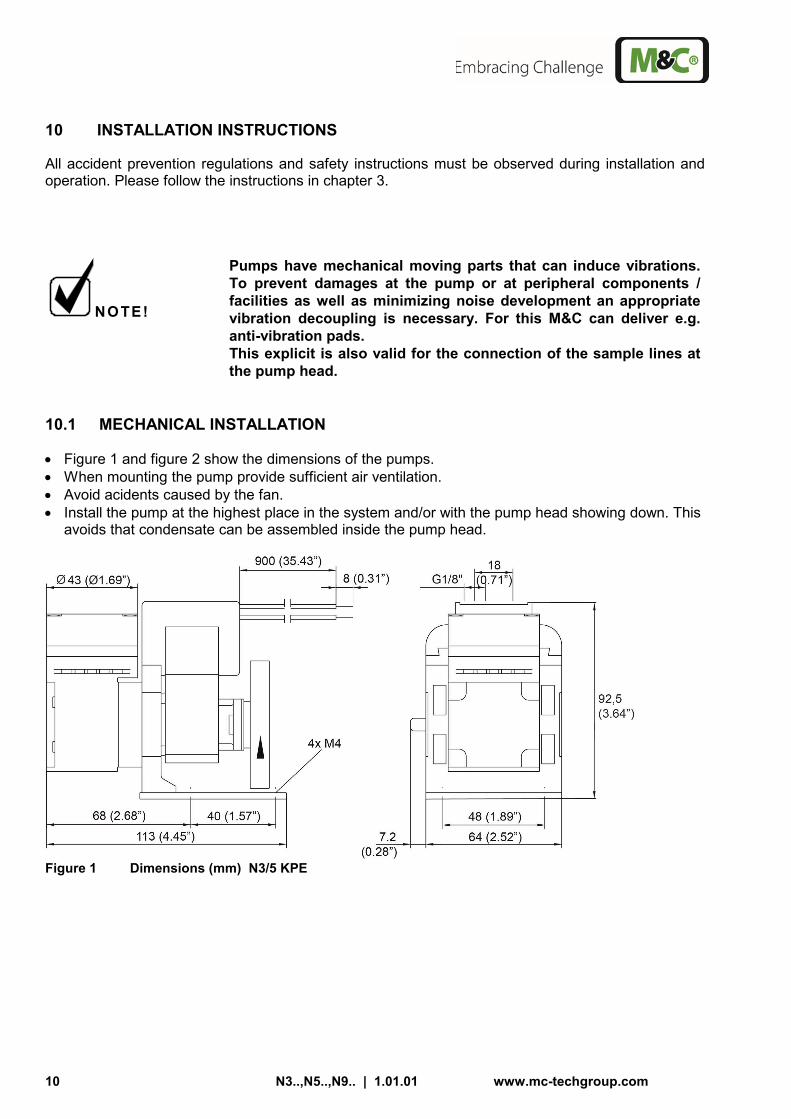
10.1 MECHANICAL INSTALLATION
• Figure 1 and figure 2 show the dimensions of the pumps. • When mounting the pump provide sufficient air ventilation. • Avoid acidents caused by the fan. • Install the pump at the highest place in the system and/or with the pump head showing down. This
avoids that condensate can be assembled inside the pump head.
Figure 1 Dimensions (mm) N3/5 KPE
www.mc-techgroup.com N3..,N5..,N9.. | 1.01.01 11
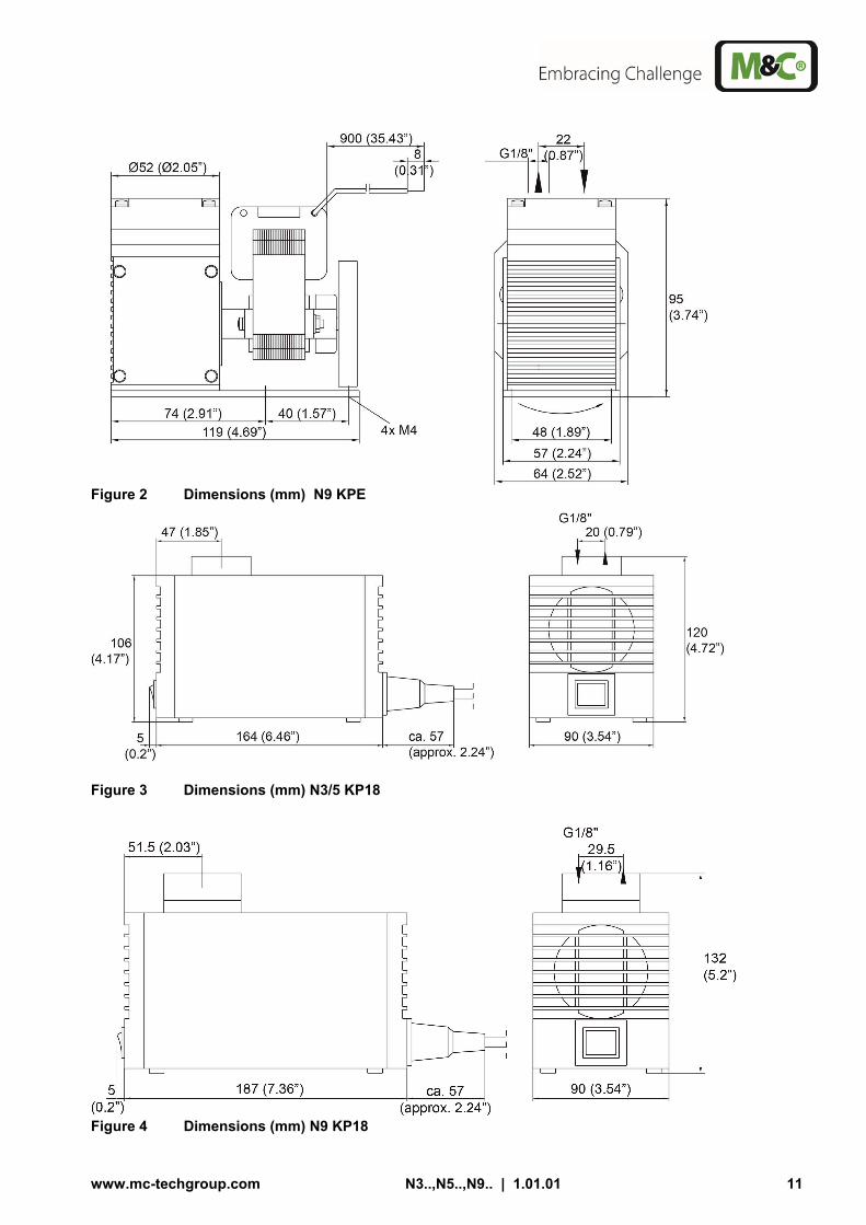
Figure 2 Dimensions (mm) N9 KPE
Figure 3 Dimensions (mm) N3/5 KP18
Figure 4 Dimensions (mm) N9 KP18

12 N3..,N5..,N9.. | 1.01.01 www.mc-techgroup.com
10.2 ELECTRICAL INSTALLATION
When making the electrical installation the safety regulations must be observed. In particular make sure that the electricity supply is isolated before trying to connect the pump..
W A R N I N G !
When connecting the equipment, please ensure that the supply voltage is identical with the information provided on the model type plate. The supply voltage is only allowed to deviate max. +6 % -10 % from the indication on the model type plate.
NOTE!
Attention must be paid to the requirements of IEC 364 (DIN VDE 0100) when setting high-power electrical units with nominal volt-ages of up to 1000 V, together with the associated standards and stipulations. The main circuit of the pump type KPE must be equipped with a fuse corresponding to the nominal current (over current protec-tion); (EN 60335-1) The main circuit of the pump type KP18 is equipped with a fuse corresponding to the nominal current (over current protection); (EN 60335-1) For electrical details see technical data.
• The earth wire (ground) must be connected to the motor. • The pump must be installed so that contact with live parts (connections, possibly windings) is
impossible. • We recommend that a fuse is installed in the motor supply circuit; the operating current is given in
the technical data
Mains 230 V
N
L
WH
BK
RD
BU
Connection Mains 115 V
N
L
WH
BK
RD
BU
Connection
Bridge
Figure 5 Electrical connections
www.mc-techgroup.com N3..,N5..,N9.. | 1.01.01 13
10.3 PNEUMATIC
• Remove the protection plugs from the port threads (thread size G1/8“). • Accessories like hose connections are screwed into the port threads by sealing tape (using M&C
connectors sealing tape is not necessary). • Connect the suction and pressure lines. • Arrange the suction and pressure lines so that condensate cannot run into the pump.
NOTE!
The pump must only be used in the conditions specified in the technical data. The pump should be installed away from heat sources and freely ventilat-ed to prevent any accumulation of heat. For outdoor installation, the pump must be installed in a housing protect-ed from frost in the winter and sufficiently ventilated in summer. Exposure to direct sunlight must be avoided.
11 SUPPLY LINE CONNECTIONS
11.1 HOSE-/TUBE CONNECTIONS
The gas inlet and outlet hoses/tubes are connected on the top of the pump. Standard G 1/8" thread-ed joints are available for the connection of the gas sample lines. The appropriate tube or hose threaded joint connections are available optionally from M&C.
NOTE!
Do not confuse hose-/tube connections for sample gas inlet and outlet; the connections are labelled accordingly ! Check for tightness of all sample lines after connection (see 11.2) !
When connecting the sample gas supply hoses or tubes to the corresponding threaded connections, pay attention to the following points:
NOTE!
The tightness of the connections can only be guaranteed if the end section of the connection hose/tube is flat (use a hose-cutter) !
• Loosen the sleeve nut of the clamping-ring threaded joint by turning to the left. Take care that the
nut is removed carefully from the body of the threaded joint to avoid losing the clamping ring which is mounted loose in the nut.
• Push the sleeve nut over the connection hose/tube. • Push the clamping ring onto the connection hose/tube with the thicker bulge pointing to nut. • Push the hose/tube onto the supporting nipple in the threaded joint. • Tighten the sleeve nut by hand. The hose/tube is now mounted in such a way that it cannot slip and is resistant to pressure.

14 N3..,N5..,N9.. | 1.01.01 www.mc-techgroup.com
12 STARTING
Specific safety instructions for media being handled must be observed. Before pumping a medium, the compatibility of materials of pump head, diaphragm and valves with the medium must be checked (for pump materials: see table 1). The following steps should be carried out before initial start-up: • The pump must not start against pressure or vacuum. When it is switched on the pressure in the
suction and pressure lines must be atmospheric. This must be so even when the pump restarts af-ter the power has been cut off for a short period.
• The maximum permissible operating pressure (see technical date) must not be exceeded, even when the flow is restricted.
• To prevent the maximum permissible operating pressure being exceeded, restriction or control of the air or gas flow should only be carried out in the suction line.
• If restriction or control of the air or gas flow is made on the pressure side ensure that the maxi-mum permissible operating pressure is not exceeded.
• When the pump is at a standstill the inlet and exhaust must be at normal atmospheric pressure. • Diaphragm and valve plates are the only parts subject to wear. Wear is usually indicated by a
drastic reduction in the pneumatic performance. When replacing parts proceed as described in section 10.
• Ambient conditions: see technical data. 13 CLOSING DOWN
NOTE!
The area in which the pump is situated when not in use must be kept free of frost at all times!
If the pump is putting out of action for a short time no particular measures need to be taken. 14 MAINTENANCE
Before the maintenance work is carried out, it is necessary that the specific safety procedures per-taining to the system and operational process be observed!
W A R N I N G !
It is necessary to take the pump off the mains before any assem-bly, maintenance or repair work is carried out!
Diaphragm and valve plates are the only wearing parts of the pump. They are simple to change. A wear is indicated by a drop of the pump capacity.

www.mc-techgroup.com N3..,N5..,N9.. | 1.01.01 15
Figure 6 Sectional drawing N3/5 KPE
Figure 7 Sectional drawing N9 PE
Parts and tools required: • Valve plates, sealing rings (2 for each pump head) and structured diaphragm(s) • Screwdriver no. 1
NOTE!
Always change valve plates, diaphragm and sealing rings at the same time.
Change the diaphragm, valve plates and sealing rings in the following sequence:
• Remove pump head • Change diaphragm • Change valve plates and sealing rings • Refit pump head
Proceed as follows: 14.1 REMOVING THE PUMP HEAD TYPE N 3/5/9 KPE/KP18
• Make a mark on the head plate 3 (N3/5 with metal frame), intermediate plate 2 and housing 1 with a felt-tip pen. This helps avoid incorrect assembly later
• Undo the screws 4 in the head plate with the intermediate plate off the pump housing.
3
4
2
9
1
13
16
14
11
7 8

16 N3..,N5..,N9.. | 1.01.01 www.mc-techgroup.com
14.2 CHANGING THE DIAPHRAGM TYPE N 3/5/9 KPE/KP18
• Turn the fan to bring the structured diaphragm 9 to top dead centre. • Lift the edge of the diaphragm and gripping it on opposite sides unscrew it by turning anti-
clock-wise. Please take care that the diaphragm spacers 11 on the threaded portion of the diaphragm do not fall into the housing.
• Take the diaphragm spacer 11 off the threaded portion of the diaphragm and retain them. • Check that all parts are free from dirt and clean them if necessary. • Put the diaphragm spacer on the thread of the new diaphragm. • Turn the fan until the connecting rod 13 is at top dead centre. • Screw the diaphragm complete with diaphragm spacer into the connecting rod (clockwise)
and tighten it by hand. 14.3 CHANGING THE VALVE PLATES TYPE N 3/5/9 KPE/KP18
• Separate the head plate 3 (N3/5 with metal frame) from intermediate plate 2. • Remove the valve plates 7 and sealing rings 8 from the intermediate plate. • Check that the valve seats in the head plate and intermediate plate are clean. If scratches,
distortion or corrosion are evident on these parts they should be replaced. • Lay the new valve discs in the recesses in the intermediate plate. The valve plates for suc-
tion and pressure sides are identical as are upper and lower sides of the plates. • Check that the valve plates are not deformed by moving them gently. • Lay the sealing rings on the intermediate plate.
NOTE!
Valve plate and sealing ring for pump type N9 are connected to one spare part since 02/2007.
14.4 REFITTING THE PUMP HEADS TYPE N 3/5/9 KPE/KP18
• Turn the fan to bring the diaphragm to top dead centre. • Place the intermediate plate 2, with valve plates 7 and sealing rings 8, and head plate 3 on
the housing, in the position indicated by the markings. • Check that the head plate is centred by moving it gently sideways. • Place the metal frame for N3/5 • Gently tighten the screws 4 evenly and diagonally. • Turn the fan to check that the pump rotates freely. • Turn the fan again to bring the diaphragm to top dead centre. • Now tighten screws 4 firmly.
14.5 CLEANING
• When changing valve plates and diaphragm, inspect all parts for dirt before assembling the pump head and clean them if necessary.
• As far as possible clean the parts with a dry cloth. Solvents should not be used as they can attack the plastics and synthetic rubber parts. If a compressed air line is available, blow the parts out with it.
www.mc-techgroup.com N3..,N5..,N9.. | 1.01.01 17
W A R N I N G !
Aggressive medium possible. Wear protective glasses and proper protective clothing!
For recommended spare parts please see Section 16.

18 N3..,N5..,N9.. | 1.01.01 www.mc-techgroup.com
15 TROUBLE SHOOTING
Before working on the pump isolate the power supply securely, then check that the lines are not live. The following tips for fault-finding are best employed in the sequence shown.
Problem /indication
Possible cause Action/Check
Pump produces no flow
No main supply. Check power supply. Check plug for correct fit.
Thermal switch has opened due to over-heating.
Disconnect pump from mains and allow to cool. Race cause of over-heating and eliminate it.
Connections or lines are blocked.
Remove blockade.
An external valve is closed or a filter is blocked.
Open valve or clean blocked/dirty filter.
Liquid (condensate) has collected in the pump head.
Let the pump for a few minutes pumping air.
Flow, pressure or vacuum too low
Diaphragm or valves are worn out.
Change diaphragm or/and valves.
Compare the actual perfor-mance with the figures in the technical data.
The pump is not designed for this condition.
There is pressure on the pressure side and at the same time vacuum or a pressure above atmospheric on the suction side.
The pump is not designed for this condition.
The cross-section of pneu-matic lines or connected components is too small, or they are restricted.
To measure the performance, disconnect the pump from the system (smaller diameter tubing or a valve can significantly affect performance).
A leak at a connector, in a line or in the pump head.
Insulate the leak, tighten the screws, clean or exchange dirty parts.
NOTE!
If the pump does not operate properly and you cannot find any of the above mentioned faults, send it back to M&C. If you send the pump for repair please include information about the medium it was handling. In particular, if it was handling aggressive substances our engineers must be informed. If you have been handling dangerous or highly aggressive gases please clean the pump before despatch.

www.mc-techgroup.com N3..,N5..,N9.. | 1.01.01 19
16 SPARE PARTS LIST
Wear, tear and replacement part requirements depend on specific operating conditions. The recommended quantities are based on experience and are not binding. Diaphragm sample pump N3/5/9 KPE/KP18 (C) consumable parts, (R) recommended spare parts, (S) spare parts recommended quantity
being in operation [years] C/R/S 1 2 3 Diaphragm pump type N3 KPE/KP18; N5 KPE/KP18 90 P 2100 Square cap type D3, 1/8“i for N3/N5 KPE/KP18
Material: PVDF S - - 1
90 P 2120 Diaphragm type S3, for N3/N5 KPE/KP18, Material: Viton, PTFE coated
C 1 2 3
90 P 2111 Valve plate type V3, for N3/N5 KPE/KP18, 1 piece, Material: Viton (2 pc. required)
C 2 4 6
90P 2105 Intermediate plate type Z3, for N3/N5 PE/KP18 Material: PVDF
S - - 1
Diaphragm pump type N9 KPE/KP18 90 P 2200 Square cap type D9, 1/8“i for N9 KPE/KP18,
Material: PVDF S - - 1
90 P 2220 Diaphragm type S9, for N9 KPE/KP18, Material: Viton, PTFE coated
C 1 2 3
90 P 2211 Valve plate with sealing ring, for N9 KPE/KP18, 1 piece, Material: Viton (2 pc. required)
C 2 4 6
90 P 2205 Intermediate plate type Z9, for N9 KPE/KP18, Material: PVDF
S - - 1
PVDF Male connectors with G-thread (ISO 1010031) 05 V 1045 Male connector
DN 4/6-G1/8“ Material:PVDF S - - 2
05 V 1050 Male connector DN 6/8-G1/8“ Material:PVDF
S - - 2
05 V 6600 Ferrule DN 4/6 PVDF S 2 2 4 05 V 6602 Ferrule DN 6/8 PVDF S 2 2 4 05 V 6605 Union nut DN 4/6 PVDF S 2 2 4 05 V 6607 Union nut DN 6/8 PVDF S 2 2 4

20 N3..,N5..,N9.. | 1.01.01 www.mc-techgroup.com
17 APPENDIX
• Pump capacity of the diaphragm pump type N3...9 KPE/KP18
For further product documentation, please see our internet catalogue: www.mc-techgroup.com

www.mc-techgroup.com N3..,N5..,N9.. | 1.01.01 21
Figure 8 Pump capacity N3/5 KPE/KP18
Figure 9 Pump capacity N9 KPE/KP18


