N8 9 - 1259 3 I
PYRO SHOCK SIMULATION:
EXPERIENCE WITH THE MIPS SIMULATOR
Thomas J. Dwyer and David S. Moul
GE Astro Space Division, Valley Forge, PA
ABSTRACT
The MIPS (Mechanical Impulse Pyro Shock) Simulator at GE Astro Space Division
is one version of a design which is in limited use throughout the Aerospace indus-
try, and is typically used for component shock testing at levels up to i0,000 re-
sponse g's. Modifications to the force input, table and component boundary condi-
tions have allowed a range of test conditions to be achieved. Twelve different
designs of components with weights up to 23 Kg (50 Lb) are in the process or have
completed qualification level shock testing in the Dynamic Simulation Lab at GE
Astro in Valley Forge, PA. This paper presents a summary of the experience gained
through the use of this simulator, and presents examples of shock environments that
can be readily simulated at the GE Astro MIPS facility.
INTRODUCTION
The MIPS has been used successfully on numerous programs in the past three
years at GE Astro. In general, all testing done to date has been successfully com-
pleted with all pre-test objectives satisfied. Achieving the desired Shock Response
Spectrum (SRS) for 12 different component designs requires a dedicated and innova-
tive test staff, as well as a thorough understanding of the MIPS facility.
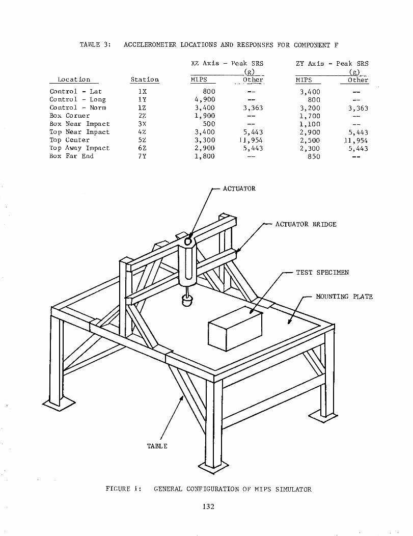
The GE Astro MIPS test setup is illustrated by Figure 1. Components are
mounted to a 122 cm x 183 cm x 1.3 cm (4' x 6' x 1/2") thick 7075-T6 aluminum
plate, which rests on a 7.6 cm (3") thick foam pad. The shock is generated via the
impact of a pneumatic actuator which is rigidly attached to a moveable bridge. The
bridge is secured to the table frame at the desired position, which typically
places the impact point within 15 cm (6") of the component. Instrumentation loca-
tion varies depending on the test objectives, but the usual control point is less
than 5.1 cm (2") from the component on a line between the impact point and the
test Specimen. A typical triaxial accelerometer response for the control point is
shown in Figure 2, along with the time history of the shock pulse.
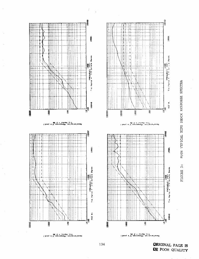
The data to date indicates that the MIPS test environment is relatively con-
sistent from test to test. Because pyrotechnic shock results from an explosion
and is a high frequency phenomena, the actual pyrotechnic shock environment tends
to vary considerably from firing to firing. However, comparison of the SRS for all
axes indicates that the MIPS results are relatively repeatable. Although there are
some exceptions, the MIPS shock environment tends to have less than i0 percent
variation from test to test, which is a considerable achievement for these types of
env iro nment s.
The MIPS at GE Astro has been used to perform shock qualification testing on a
wide variety of components. The majority have been flange mounted black boxes with
weights up to 23 Kg (50 Lb) but the fabrication styles have ranged from laser
welded housings to cast aluminum boxes. The housing fabrication method determines
125
pRI!_3Ii_DING PAGE BLANK NOT FILMED
https://ntrs.nasa.gov/search.jsp?R=19890003222 2018-09-22T12:42:43+00:00Z
the stiffness of the structure and affects the response of the MIPS table. One de-
sign was constructed of several stacked modules and another included a free-standing
antenna. Specific devices instrumented and monitored during test have included
printed wire boards (PWB's), gyroscopes, relays and passive dampers. Modifying the
boundary conditions of the table determines the response of the table to the shock
input, thus allowing a wide range of components to be successfully tested. Several
environments that have been simulated are illustrated by Figure 3, with Shock
Response Spectrum (SRS) levels of over 40,000 response g's obtained for specific
setups.
DYNAMIC MODELS
The use of dynamic models is necessary to prevent damage to flight hardware
during setup of the MIPS table. Fine tuning the table to achieve the proper shock
response spectrum can often require up to 80 shocks. With different shock profiles
and various size boxes, each configuration becomes a unique technical challenge.
Since the control point is on the table, the dynamic models must be designed to
simulate the effect the box has upon the table. Box weight and mounting style are
the most important factors affecting the response of the table to the shock input,
but the effect of cables must also be evaluated for each case. The response of a
good dynamic model can be within 2 dB of the flight unit as shown in Figure 4.
The box weight can be simulated with separate masses distributed in such a
manner as to correspond to lumped masses within the component. Such lumped masses
include power supplies and circuit boards. Figure 4 shows the generic dynamic model
design developed at GE Astro for dual flange mounted components. Aluminum blocks
are currently used for these masses, and the design has been standardized to allow
these blocks to be used in several different dynamic models.
The mounting style is the most critical factor that must be simulated. For
flange mounted components, the effect can be duplicated via use of thin rails. The
weights, which are sized to provide the proper mass distribution, are attached to
the rails at locations between the bolts holding the rails to the shock table. The
rail should be of a similar material and thickness to the flange. The effect of
structural gussets on the component flange may be neglected for shock response
simulation, since only the immediate flange will effectively respond to the .0005
second shock pulse.
The effect of cables depends on the quantity and type of the cables. Properly
suspended, flexible cables need not be simulated. Rigid and semi-rigid coaxial
cables have been found to have a low frequency effect and should always be simulated
with the dynamic model. The cable attachment to the model should duplicate the
stiffness of the prime mounting configuration.
CASE HISTORIES
For the successful use of the MIPS Simulator, the operator needs to develop an
understanding of the nature of the shock response, as well as an appreciation of the
effect that various boundary conditions have upon the table. In general, these
modifications to the boundary conditions affect either the impact area or the table
supports. The following guidelines have been developed at GE Astro and each
particular setup employs a combination of these variations to achieve the desired
SRS:
126
Variation Resul tant
Paper (cardboard) under striker ...... Damps high frequencies
Steel plate under striker
Clamp table edges to frame
Support table on wood blocks
Jackstand under impact point
Component on transition plate
Bags of lead shot on table
Lower striker height
Reduce ram pressure
Increases high frequencies
Shifts resonance lower
Damps high frequencies
Reduces low frequencies
Attenuates all frequencies
Damps high frequencies
Evenly attenuates entire spectrum
Unevenly attenuates entire spectrum
The striker has a rounded aluminum head, which can be replaced with various
profiles to acquire the proper impact. Buffering the impact point with paper or
cardboard limits the high frequency 'ringing' of the table, but, as seen in
Figure 5, equivalent thicknesses of paper and cardboard affect the low frequency end
of the SRS differently. Combinations of paper and cardboard are often used to
achieve the desired damping. Steel, on the other hand, will increase the high
frequency content of the spectrum.
The use of a jackstand beneath the impact point reduces the deflection of the
MIPS plate. This deflection results in an increased low frequency component to the
SRS. Varying amounts of back pressure upon the jackstand will preload the table
and can be used to eliminate undesirable low frequency responses. The air pressure
driving the ram also has an effect upon the low frequency response of the table as
shown in Figure 5. Increased ram pressure deflects the table to a further extent,
and will add a 'DC' effect. Ram pressure is adjusted in accordance with jackstand
preloading to achieve the desired response.
Clamping the plate edges to the table will effectively shorten the table length
and will shift the table resonance accordingly. Supporting the plate on wood
(aluminum) blocks above the foam changes the boundary condition from free-free to
simply supported. Variations to these and other boundary conditions have allowed
the operators of the MIPS at GE Astro to meet every program specification.
Specific case studies typify some of the common problems and solutions for the
operator of the MIPS table:
Components A & B are typical aerospace black boxes consisting of multiple
mechanical and electrical components coupled with numerous printed wire boards
(PWB's) supported within the rigid containers. Integration of passive viscoelastic
damping treatments into the design of spacecraft component mounting structures
(including PWB's) significantly improves spacecraft reliability. An additional
benefit is increased damping in orbit which reduces response to onboard disturb-
ances. Constrained Layer Damping Assemblies (CLDA's) are typically applied in
strips running lengthwise across the board with a Viscoelastic Material (VEM)
sandwiched between a stiff constraining layer and the board surface. The CLDA is
placed to maximize the strain energy in the VEM, although this is not always pos-
sible due to PWB component mounting. All PWB's within Components A & B have CLDA's,
as well as several other critical box surfaces. A typical PWB with CLDA is shown
in Figure 6. A unique Component B feature is that boundary conditions were applied
127
to several of the PWB's by strips of flexible silicon rubber pads forming the
interface between the container bottom and PWB surfaces on some boards.
During the vibration and shock testing, the boxes were internally instrumented
for the purpose of determining the internal dynamic environment resulting from the
shock application and the effectiveness of the passive damping treatment used to
reduce the response of PWB's. The input to the components was characterized by
triaxial locations less than 7.6 cm (3") from the component mounting flanges, and
the internal and external component responses were measured with microminiature
accelerometers. The PWB accelerometers were positioned near the center of the
PWB's to measure the vibration normal to the board. The remaining accelerometers
were located on the covers and structural bulkhead. A triaxial location was in-
cluded at the upper corner of the component near the application of the shock to
evaluate the amplification of the overall box structure. Additional detailed in-
formation is listed in Reference [i].
The general test geometry is illustrated in Figure 7. Two shock applications
were applied for each condition illustrated in Figure 7, with functional tests
both before and after the shock applications, and no anomalies were detected in
any test.
The data summarized in Table 1 and Table 2 provides a definition of the en-
vironment within the components resulting from the MIPS simulation of the pyro-
technic environment. They indicate relatively high SRS levels for electronic parts
mounted on the PWB's on the order of 1-2000 g's. The PWB's do provide a signifi-
cant attenuation of the MIPS plate environment which ranged from 6000-13,000 g's,
and the component structural environment (3000-7000 g's). This attenuation is
expected in view of the relatively low resonant frequency of the PWB's. The
PWB's having the lowest resonant frequency typically have the lowest SRS, while
PWB's with the higher resonant frequencies had the higher SRS. Responses in these
boxes are thought to be typical for similar application throughout the industry
and can be scaled for other shock environments by analysts wanting to determine
PWB response characteristics for their application.
Component C utilized a box design which consisted of a heavy, cast aluminum
container. This design required the mounting bolts to have an excessive grip to
pass through the thick flange. To compound the problem, the customer required the
use of titanium mounting bolts during test. Since the modulus of titanium is
lower than steel i.i x i0" PA versus 2.0 x i0" PA (16.5 x 10 6 psi versus
29 x 106 psi), the extra grip length and the bolt size (#8) were a concern. As
feared, after a number of setup runs with a dynamic model, several bolts deformed
and one bolt snapped at the mounting plane. The use of titanium bolts required
a higher ram pressure to achieve a similar shock response as high strength steel
bolts. It is believed that the titanium, with a lower elasticity, stiffened the
table much more effectively with the component than the steel. The steel bolts
would elongate slightly under the shock impulse and would tend to be more for-
giving than titanium. The test was successfully completed when the mounting holeswere enlarged to accommodate #i0 bolts, which were also titanium.
Component D testing was the first attempt to use a transition plate for the
MIPS table. Currently, each component is mounted directly to the MIPS plate,
which requires an ever increasing amount of holes. Concentrated hole patterns in
the plate affect the boundary conditions of the plate, which in turn add a new un-
known to the setup. A transition plate for each component would have mounted to a
common bolt pattern in the table, thus maintaining the integrity of the setup. The
transition plate for Component D was designed to fit an existing hole pattern which
128
surrounded the component mounting pattern. A 1.3 cm (0.5") thick aluminum plate
was used for the adapter. This method was successful, but the setup was difficult
due to the effect of this secondary plate. While the MIPS table design was driven
by the need to have the plate 'ring' near the crossover point, this secondary
plate had its own resonance which made shaping the shock response difficult. For
this reason, it was decided to continue with the original method of mounting
directly to the large MIPS plate.
Component E was a small passively damped device which required testing in
three orthogonal axes. Normally, the MIPS requirement is for the shock to be
solely in the plane of the component mounting surface. This test was accomplished
by mounting the device in a metal cube, which could be rotated to achieve the
three planes. The cube was fabricated from solid steel to provide maximum trans-
missibility of the shock impulse. The device was not only instrumented with
teardrop accelerometers, but also contained mirror cube mounts for collimator
readings. Although this method would not be feasible for large components, it has
proven to be an alternative for small components requiring three axis shock.
Component F was unique in that it sustained catastrophic internal damage and
mounting feet deformation during prior pyro shock testing at another facility.
That facility (Figure 8) is quite different than the MIPS facility, thus affecting
the path taken by the shock wave from the impact point to the unit. In addition,
in the previous test, the flight unit itself was used during system setup with some
67 hits made during the calibration resulting in probable unit over testing. To
resolve the question of whether the component failures resulted from being over
tested/over exposed or whether the design was susceptible to normal axis shock,
another unit was tested at the GE Astro MIPS facility.
The shock spectrum illustration in Figure 9 was applied to the component.
The axis definition and instrumentation details for this test are given in Table 3.
The control accelerometer was located within 5.1 cm (2") of the mounting foot, and
a second reference triaxial accelerometer location was approximately 17.8 cm (7")
laterally from the central control as indicated in the figure. All response
accelerometers on the component were bonded to tape which was secured to the
(flight) unit.
The test sequence consisted of applying three consistent shocks with a dummy
in place of the flight unit for calibration, and then a single shock to the flight
unit. The procedure was repeated when the unit was rotated 90 degrees. The
normal axis input, as measured by station i norm, is shown in Table 3 for the XZ
test and the YZ test. The three lines in the vicinity of the solid response curve
represent the desired levels with +3/-6 dB limits indicated. It is clear that in
no band did the response exceed either the +3 or -6 dB limit.
Results of the pyro shock test are summarized in Table 3 with peak time
history values tabulated. The unit was exposed to an approximate SRS peak input
of 5000 g's in both tests and, upon examination of the test data presented in
Table 3, it is clear that the component responses were grossly different between
the two test methods. For an approximate normal axis input of 3300 g's, responses
at the top of the component for the MIPS test were on the order of 2500 g's,
whereas responses with the other Impact Facility illustrated by Figure 8 were
some 12,000 g's. It is obvious that the unit as tested on the MIPS assembly
experienced grossly lower response levels than experienced on the other test
apparatus. The primary difference is due to the path the energy takes before
reaching the component and a 200 Hz component response that was magnified by a
system resonance with the Impact Facility in the same frequency band. It was
129
concluded that the MIPS setup is a better representation of the actual environment
that the unit will experience in flight and imposes far less structural risk due
to the test assembly than the Impact Facility.
CONCLUS ION
The MIPS facility provides a unique capability for repeatable shock testing of
large components. The manipulation of the boundary conditions allows a Wide range
of test specifications to be met. Peak levels of 40,000 response g's have been
reached with the bare table. The MIPS pyro shock simulator at GE Astro has been
used to successfully qualify a variety of components for flight use. Achieving
the desired Shock Response Spectrum for different size boxes is a matter of skill
and experience, but will always remain an art. This paper presents a few of the
'tricks of the trade' necessary to succeed in using the MIPS. The information
presented herein was gathered through the testing of twelve different components.
Each component required, on the average, approximately 80 setup shocks on a
dynamic model to achieve the proper shock spectrum. As the database grows with
each new component, and as communication between MIPS users increases, the setup
time and cost can be dramatically reduced.
REFERENCE S
[1] T. J. Dwyer: Design and Dynamic Testing of an Instrumented Spacecraft
Component, 58th Shock & Vib Symposium, NASA Conference Publication 2488Volume II.
130
TABLE i: ACCELEROMETER LOCATIONS AND RESPONSES FOR COMPONENT A
XY Axis - Peak SRS
(g)
ZY Axis - Peak SRS
(g)Location Station Hit 1 Hit 2 Hit 1 Hit 2
Input - Norm IX 12,930 12,623 1,706
Input - Long IY 6,083 6,131 6,314
Input - Lat IZ 1,694 1,902 10,629
Box Corner 2X 3,406 3,362 4,728
Box Corner 2Y 5,921 5,761 5,522
Box Corner 2Z 4,341 4,179 3,147
PWB - 5 3 873 928 393
PWB - 6 4 3,771 ....
PWB - 7 5 .... 763
PWB - 8 6 1,086 1,280 1,207
PWB - 9 7 1,514 1,654 938
PWB - i0 8 980 1,248 1,771
PWB - ii 9 ......
PWB - 12 i0 1,174 856 1,918
PWB - 13 ii 427 650 532
1,808
6,280
10,560
4,623
5,524
3,289458
557
650
1,371
1,043
1,867
2,007
1,096
TABLE 2:
Location
ACCELEROMETER LOCATIONS AND RESPONSES FOR COMPONENT B
XY Axis - Peak SRS
(g)
ZY Axis - Peak SRS
(g)Station Hit i Hit 2 Hit i Hit 2
Input - Norm IX 4,000 4,000 4,000 4,000
Input - Long IY 4,000 4,000 3,600 3,600
Input - Lat IZ 850 900 650 750
Box Corner 2X 2,100 2,250 2,250 2,250
Box Corner 2Y i,000 900 900 900
Box Corner 2Z -- 1,950 1,700 1,650
PWB - 4 4X 550 550 500 550
PWB - 4 4Y i,i00 1,200 550 800
PWB - 4 4Z 350 300 1,000 1,050
PWB - 5 5X 275 300 125 130
PWB - 6 6X 450 375 170 180
PWB - 7 7X 450 450 150 135
PWB - 8 8X 375 360 95 165
PWB - 9 9X 260 270 150 ii0
PWB - i0 10X 450 500 14 18
PWB - ii IIY 250 260 500 650
131
TABLE 3: ACCELEROMETER LOCATIONS AND RESPONSES FOR COMPONENT F
Location
Control - Lat
Control - Long
Control - Norm
Box Corner
Box Near Impact
Top Near Impact
Top Center
Top Away ImpactBox Far End
XZ Axis - Peak SRS ZY Axis - Peak SRS
(g) (g)Station MIPS Other MIPS Other
IX 800 -- 3,400 --
IY 4,900 -- 800 --
IZ 3,400 3,363 3,200 3,363
2Z 1,900 -- 1,700 --
3X 500 -- i,i00 --
4Z 3,400 5,443 2,900 5,443
5Z 3,300 11,954 2,500 11,954
6Z 2,900 5,443 2,300 5,443
7Y 1,800 -- 850 --
ACTUATOR
<
ACTUATOR BRIDGE
TEST SPECIMEN
MOUNTING PLATE
TABL E
FIGURE i: GENERAL CONFIGURATION OF MIPS SIMULATOR
132
liXIlO{1%OZllqOD _IO .qSNO£S2_I IVIXVIff£i qVDlcIil :Z _l_Iflgl_I
asuodsaH six V I_a_q
001
0001
00001
asuodsaH six V IwmXoN
001
0001
",5_0
-z
%.
T_O
@
asnodsa_I sTxv l_Ipn]T_UOq
00001 BOOT
)i)i))i I_:: i)i)_)!i _'_'_ :TTTTTT ) ;_;)_ _ii_iii2i211i22Zi2Zi_2..........ii..............................................iiii211211iZiiii_21Zi..........i;1211221121122121;211211121121122112111112111
iiii i i ) _! i !................_'""'_"-'"'_ : ")'"'"")'""i'"'-"'"'"'"'""" _ ............i:! ! ! ! i i i' !i i i i i i ,__i,1..,f ,./I]]IZ21Z21]Z]]]IITIIIIIZ...........i21.............................................IIIZI]]I]T]I21Z21121Z]]I)ITII!;....iZZ:.Z]]I[]I]]]]I_..I2:.L.2]:.-._..._...._,...._.....:.........-:...........i.................)................................._.............._......_....._..-...,_................-....._::................
::1 _:1: _:::: _::1:: _:::::: !::::1:::: T::::::::::: !:22:1:2::::::::: ::::::::::::::::::::::::::::::: 12:: _:::: _::2:'i ======================================================================
• i i i l _ i_i ! !/_ i :..L..L...L...i-....L....-.i...........i.................i.........................._...L._..i.....L.....L.-..,,_:L-..-._................._.............................
....TTT"T"i .......!...........)...........I ........ I...............T.............................
001OT
001
0001
0000I
asIncI _1ooqs 7o K£[O]STH OmT£L
E0-300" L E0-]00"5 E0-300"_ _0-300"I _0-300"_-: • £0_300'£-
)
'i ................... i
................ i .................
)
......................................i........................................................i...................i.......................................i................................
_5%.
_o
£@+3;_' 2-
?t_
m
o
0
am]o_'z
15B+305' 1
¢_35_ '_
eSI_300 '
c_
"i:i"L4i.. ............................ i i............IiH4..L.L..i.......J............i.i.i.H..L.L4....._ ............
:::::::::::::::::::::.........jii iii i i-i ............_!iii!N i............iiili i.tttti:-i_ .........t}}f}H+ i ............i iif!H+f ..........xiT?N!I............,'"'"r-"-rl.............:"!r.'..r"rr-T............-.......iiii!ii -i ............iiiui<i ............
Jli!iiii i !iiiiiii i•fMfi__ ..........rT-q-Tiiiiiiii iiii!!i! i iil l ii idii ................iiiiiNdd -iHf i_
i ii iiiiiiii i iiiiliiiiii iiiiii!i i iiiili
£, k]iill i iiiiii!i i ,_ix!:!:Nx::!::i:_:-:i:i;_i:ixL:i............i:i:i:i:ixi::xi:::il..........°_"iiH!d !...... _:M ............_i-ifl _--..........._
•4...-4.......'......'_i I..:--%:,, <..'..:-_:...............-.H$$..£..i...--- .--...........
i THNFT............iTTTH!i _ -iiiKN _................._,•_i!!ii i+ " +' -":"_i ............._+++_...i;.,_-.:.i:-..ii! i i i .-_ _-_ .+..:_,.-++i+++.+ f-ti]i]i]] ! _...........".L'..'..L..'....L...4............i._i4.L..4...i ..::{........::_.i.i._.i. _...i.._....4...........
i:
(_d _,0 oeuad_e_) uol_eleoo _
H':_li/_hiif_'f............;ffHHf!-i::_::':::';:f!ffHiff_:_::'::: '...........::H;:r_IH::::i:::;:I::::::::::::ii_:i:i::i_:i::::i_:::::I::::::::::::H:_i_:N::_::i_::_:_::
.i.iit;.i..ii..i....i...i.i............iii..i.H...i....i.......i............i.i.i.K.i...i....i......i..........:.].iJ_..]H....i...i.i............iii.i.H...i....H............i.i.i.i..]..i...i....i.-i...........
.i.iJlH.£i...i.i............ii.i.i.i..i...i....M............i].i.!ii._i..iM............i_Niiii ii iiiiiii! ! iiiiiii i i
•i-ii-._-ii-.i--..i..+i............iii.i-i..i...i....i..-i............i.i.i.i.-i..i..$..-i-...--_..........::iiiiiiiiii iiiiii}ii ii iiiii!ii i .-ii.i..S....N.i............iii.i.H..i...i_.i............i.i.iH.N..i....i............i i iiiiiiii iii i iililiiiiii iiiiiiii i iiiiiiii i
•f!ifixf 'f'_fffff!f!i ............fiifHiff ............•iHiii_i ..........:_fifiii-i ............ifi{iiiii .........•_.i..H...i....i...::.L.:...ii_._,H...i....i.......i............i.i.i.H..i...i....i......i.........iiiiii i",'iiiNii i iiiiiiii ii-i..i..H....f....-f......:..ei.f.H:.-i....---i............iiiiiTiit .........i iiiiiiii ifHfi.:.'f ............ff f-.._-i .!<i---_] ............Hif ! f i}--{ ..........
i i iiiii"ki"-.ki"_ iiiiiiii i_i i iiiiiiki i\\iiiiiiii iiii ii i iiiiiii<ii_ _iiiiiii i
g
=1-4
_.:_ij
0
i :i:i::::::::::::::::::::::::::::::::::::::::::::::::::::::::::::::::::::::::::x::::::::::::::::::::::::::::::::x::i::x::::-
._..._....(......_..........u.]._._u...._..i._........_.u._.._.._._...._...._........._.u._..u.._...._..._.......!i.i.i.i....!....i...-.ii.i.i..ii..N...i........._ii._.i.i..!....',.....i.........i.',.i.i.ii..N...i.......:•i.i.i.!.i....i...._,..........i.ii._i..ii.i..i..:.i.........i.i..ii..i.i..!...H.........ii..i..H..i.i-i....i........._]i!iiili i ili_iiii !:i ii;iill i ! iii[i;! i i I
:iii",ii'<i........._,_!}9ii<,I'_........iiii!iiH-i_!_!! ................Iii{iii'}_ ii',!iiiiill iiii!iiii ':_ii_',::_ I
'i i<iU!iiii..........iHiii...............iii!!i i\iii.!ii!! ! !iii::i_,i i _:_i:,',::i_ i 0_ili!!i i "dii]iiii ili iiiiill i- i i ._,0iii:::: _ :: _ii_i!ii !:! ::::iiii :, i _t-i
.i.::._.i.._..M.4_ii i i i i ......... iiiii :'ii_ __ _'..._.:..k....k.'_....._._4.!i.. i:: - ._..-....-i_----: ................. _z [q
.........._..............i_"i{-'ki%-:_"-.--.'_...i.}-}::..i-..}-.i....i....+...-..+H.{-.i.-_.}.+.-!-'::,_
iiii_ i _ ::_ii!! !",.i'.!", i_'._iiii _ _ !!iii_ _ _ _':
::iiii:: _i i \"-ii!i"_! i iii i : _ i ._i ". i;.iii i.i L,
KTTTTT .........[iiiiNiYf%i_.ii!_. f _ _ i
: iiii]!]}! i iiiiiil i_i ii::_Pi-:: }, iii!i_ _::ii::ii i i ii!::]ii i k ". { "..Hi]i! i ! ii]ii]] i i", i '_-.. '... *
-_rr- _f............ttfttttti ............t!itHit-t:
:_._.H..._.._:....._............_._.;.u..._...._......._............_.i._._..i..;...i....i.......;..........::::::::::::::::::::::::::::::::::::::x:::::x:::::::i:::i::::i:::::x...
ii "<ii iiiiiii i i iiiiiiii i "
:i.i iI_4............iii.i-i..Nd-..i..i-i.i.i..i.-i..-N--!
•il i ii iiiiiiii i iiiiiiil i
ii ...._i i,, iiiiiiii i iiiiiiii i.i ',,iiiiiiii i ii{iiiii i _
•ii i'\%, ii,_iiiii i iiii{ii__ _:....... _ ..... i ...... ]]]]il ] ] ] _N_
" "}"" "" l } I'" }""" +""" }" I + _'_: I + } +" } {J"" l "+ ....................... +'_ "_" + I I _" ' _" I "_ I'' I + I I'" I "+ ......... _ I
I-i-f!--i--fHi::i_.i:ffli--i----i............fi-ii-iff-f----f----:--::_
"T ......... _T: :T'rT" _ ""_'"""_ ............ T'i'_'T"_"T'"i'"'_'""" _ .......... I__
_ _X_-.,_ .......-_u_..........................._.<,:!TTTTTff ............fif:Ti'iiTi::i ...... iiiiiii i i . S_.
+fJJ+++} ........:........ fx rliN}i+ f..........._'
iiiiiii i iiiiii_i i .:,s._ii._i_ _ "•_._.-_.._.-f.-b_--_............÷÷ffi..i...i-...i.--d...........:_i._-.-i.-i--:id-.-.-.i............iiiiiii i iiiiiiii i i_Kii',i ]
IJiiiiil i iiiiiiiJ i iji!_i',ii,,. I ..l_iiii!! ! ii_ilil i _ iiii_bN.".i kl s)
E_
o9
o9
<D
b9
H
H
E_
_4
OF_
c_
_4
c,DH
qff Z -- _J_W o!1
(_d _ _od_) UOl$_d_[_oo_
qff _ - _H_W o!1
134 ORIGINAL PAGE I$
O__ POOR QUALITY
_IZ(ION DI_VNX(I 7VDI£XI GNV NDIS2(I _HDI_I_ _0 NOSINVd]_OD :_ ._NNDI.g
CN
]/
/
I
I0
o
i " . • ,0I
_1
gggBl
I
_a
SNOI,T,VINVA £fl£NI ._O_I0_ _0 SNOSINV£HOD SNS :[ ZNflgI_
men q]eaua[ Iode_ 70 saoaT£ x!s
l_OOlB 1 CZH) ,LON:3rli03_IAi_81 8BI
iiiiiiii i i iiii i i:y_:_xxN::;Zxx:y_XXxyZ2xX:x2i::::2x::xi2::2::XX2::x:xX_:_x2;ixx;i::2_""-._"-""._ ........... ± ............ ::::?::::::::::::::::::::::::::: 001
'i i i i i i i i _ _ .... i i .'_ ! i _ i i i i _ ! i i ! i i i i ..
"T-T"-'"'-'--r'"'-'T' "! ................. _.............................. i'"t'-i'-"i'""t"-"f.....,.t ........... _ ................ "....: ......................
....ii---_ -i.................i..............................i...4..i..4..4......4...4..........._.........._._........................::
:_ _ - ÷ - ÷ .i.................i.................................-..............._.........-...._........4:...............-.......:..................:,.+...+.....L...L.....L......_ .......... :::::::::::::::::::::::::::::::::::::::::::::::::::::_:::: ::::: :::::_::::::_::::::: ::::::::::::::::::::::::::::::::::::::::::::::::::::::::
,1 : : _ ::_::::::: _ ..................................................:::::::::::::::::::::::::::::::::::::::::::::::::::::::::::::::::::::::: °:_: : _::::_: _ " _ .......! i _ ! ":'*'"'"'_ I'"?'"T'"T'"'t"_"'""'t ........... _-'-'"-"'"'I 00_I1
• i i i i i ! i i! i i.4 i _ .-_J---'-T ..I:FiL_:i:L i................i..............................i<k:4 _ _ ..........._................i...........................::__iii";i___:%::-i:-:"-:7 .......... i_ i i i _"_ i _iii li ..
:.:_:_.:_17i7:_: :::::::::::::::::::::::::::::::::::::::::::
I
o_
%,
_m
me_l q_eauo_ p_eoqpae D
_@OBIEZH) AON:TIO3_3
......................................................................................................................iiii i i i i..................................................................,..............................N.4,.4....._......_........_........................................................::i i i i i i
.,._..._,..._....._......_........_................::::::::::::::::::::::::::::::::::::::::::::::::::::::::::::::::::::::::::::::::::::..........._.........::::::::::::::::::::::::::::::::::i i i ! i i i iii i i i i i i ...........>.......
...........i _ ......__--__-+- ...........-................-.:-:,....................--T--- _.................i..............................!-i....P..-......-........- i :.:-,C....................._.:;_........f_t_ ...........!.................i..............................N-.............._......_........_..........._-_::........._.............._.:.........
-'f"-".'f....-......f.......÷ ........... i ................. i ................................. #.............. z.....i.......i........,_.=.. _ _ "
::H:: :: _: :_ _ .... i i::: :::::::::::::::::::::::::!++"!+"+"-_';"_ ............... _-: ................
: i i:.,b.{.:-£- i................._.................................i.._.:.4..........):....'.....i................i...........................:....: ..............: ':"i:---:--:"-: ::"::":::-: '_-.....-....i ...........................::
i i :::::::::::::::::::::::::::::
aBl
01
001
gggt
ggBB[
o
bmm
er)
e_nssaa d m_ ISE 0[Z
tpueg e_e%:O E/l - =MJtN =!1
.............. _.............................. :::::::::::::::::::::::::::::::::::::::::::::::::::::::::::::::::::: ...........................'"?'"?'"'?'""?"""?'""-"? .......................................................... i-'.+....i....-i.....+......+........@ ........... :::::::::::::::::::::::::::::::::::::::::::::
il ! i ! i i! i i i r i / •
• i i i i i .................i'"T"'T'"T'"'T'""T"'""'T...........?...............:_.................::::"::'".....T'"T'"T""T"'"_'"'""t...........i.................i..............................i_""i!-----._ ..........._......._.:..._.............::::...,_:.::
:.-:..i::::_:::::i::::::::::::::::::::::::::::::::::::::::::::::::::::::::::::::::::::::::::::::::::::::::::::::::::::::::::::::::::::::::::::::::::::::::::::::::iTi'"Pt'""i ...........i.................i................................._..............:::::::::::::::::::::::::::::::::::::::::::::::::::::::::::::::::::::::_::!;!!ii;iE;!ii!!i;Eiiii;ii!!i!!EE{EE!!!!E!iiiEE!!!EE_Ii!!!_!!ii!iEH!i_iii_,'i!!!ii{iEiiiii._i::!:::;!!.::!:::_iii• i i i i _! i ! R _....... .
i ! i i i i _i i._ ..f i! i .,:.'t/:f=Xnt: t"2 .............................i..._:....i.....*..-,i.....:4:........._................_.........................:...:4 _ _ _ _ _ ; ............. _i ! i i _ ..:.i. i i ! i i i ...............i..............................;?""_;F__"?T ...........T................?...........................::
IR_g_g
001
gggl
gggB[
IO
7m
o:msso:_£ mL_I ISd 00Z
0001
I
IO
0
t
X
<
o8
ORtCtNAE P_G_ I_
DF_ POOR QUALI.T_
FIGURE 6: TYPICAL PLACEMENT OF CLDA UPON A PWB
CONTROL
ACCEL.
(STA i)
MIPSPLATE
ZY
AXIS
BOX
CORNER
__ / (STA 2)
r¢ IMPACT
PO INT
XY AXIS
FIGURE 7: TYPICAL TEST GEOMETRY OF BLACK BOX
137
ORIGINAl; PAQE IS
OF. POOR QUALITY
UPPER CONTROL
ACC EL EROMET ER
IMPACT BLOCK LENGTH - 243.8 CM (96")
IDTH LOWER CONTROL COMPONENT F
25.4 CM (i0") BEAM (ALUMINUM)
THICKNESS - 2.5 CM (i")
TAPE BUFFERS ACCEL EROMETER
FIGURE 8: NON-EQUIVALENT IMPACT SHOCK FACILITY
i
UQ.
i
b=
oOP4
.'.1
II,,"n.'L
i=ll_
oa
;0000
L000
L00
10L00
,.'.._...-:.........;........-........;..-...÷.:..........-........÷--.'..÷;..'i...'.!-...÷.'.!.........:.........;........".........:.......i-:........."........÷-.....÷."...÷...-_.-.-.'
............................. _................ _ .................... $ _ i :i-_ i .............................. i ...................... " : :........ i" i .......::........i......:'...._.:..L._:::i..............................h:::::'""................:.....................:.':;:::.'::.
.i i i _ !,. ! !."' .-'_'----'_\ : i _ i i _ _............................."................+...........t........_-:¢:_i ............................._..........._..+._._--.._;,_:.÷=.._..:.......•............;._.........:._........_..-..:.,+....:._.:;e......_...-4:.:i i 2" ._'" •
........ i..............................i.................i..........._,........L LLLL::::::::::::::::::::::::::::::::::__::::::::::::::::::::::::::::::::::::::::::::::::::::::::::::::::::_.t_._;............................. ;,, ............_+ ........... ,$..-:-.,i,.,.,.,_..,..i..,.,i....:;-.,.i--+ .............................. i ................. i ........... ,,i,........ ,i,,,,.,,,i,,....$...._,.,_..,
, • ,.__......i.....L...-. : : : : : .. : ... :....: ...-:........................ :;_ ""!.: ........... "'"7"""'.' ........ ."'""'."'""_"'"_"".'"'! .............................. !................. !........... " ........ .""'" .."" "" ".................... 4...._: ............ _ .......... ;, ........ ;........¢.....i.....i....._...i .............................. i ................. i ........... .':'........ i"'"'t ""'t '"'-::'"t "-'....... /L_ J;1- ..... ....::" ...........1........i i Li -i ..............................i.................i..........."........:......" _ _ _
7'<<,s T:_ i _ i i i ! _ _ _ _ i iTTT......._::_ ...............-...........-........f - ! !-i ..............................i................._...........:=........:- - f f-
" f" i i i i i i ! _ i i ! i i i i............................. <'................ ">........... '_........ ?"""?""T'"'!'"'?'"! .............................. ' ................. ' ........... _"........ ? ...... ?"'"?"" .':'"'?"
............................. _ ................ _............ ¢ ........ +...... ._"'"!'""i'"'i'"i .............................. i............................ _ ........ _'"'"._"'";.""_'"._'":: ........................... ";..................................... ÷'"'"÷'"'.b"..i..-.-..-i ..................................................................... ÷"'"'÷'"'-÷'"'÷-"÷'-............................. ._................ _............ _......... ?......?.....!.....!....?...! .............................. , ................. ,........... _,........ ?......?.....?....?...?..................................................................... +.'"'".÷'""i'""i'"'f'"i ..................................................................... ""'"'f'""f"'" :'""'":: ........................... ,_ ................ <. ........... ,, ........ ,-'....... $.....i.....i...._...-i ............................................... i........... + ........ _--....._......$...._....$.:
i i ! i I I I ! i ! I ! ! i i i............................ _................. ;, ........... _. ........ .i.......4......i.....i...._....i .............................. I ................. i........... ;, ........ _......._.......;...._.-..':'..
• : :. i : : : : :: : : i i i i i i ii : : :: : : :
1000 [0000FI_.EQIJENCY (HZ:_
FIGURE 9: COMPONENT F SHOCK SPECTRUM
138