N82' 3 2 5 3 6 1. I.S.Reed.C.S.Yeh.andH.M.Sh80 Univarrity of Southern Carifomii In thir pqur a pmalkl mrhirorrurr is ddped to compzrte the haw convoh- of fwro sequencts of dim kngths using the Farpprrt munbu mpnsfann (FNTL In pwticu- Im a pipeline sc~cture is designad to compcte a 128-point M. In this FNT. only ad& tiom and bit rotatiom arr requhi. A stondad b#tl *fie? Cinztil b md@ed so tha. it petforms tkr bit mtatkm optmtion obk for VISI imphentation Introduction Fermat number transforms (FNTs) were developed to com- pute cyclic convclutions (Refs 1-3). A cyclic convolution of two sequences can be obtained by taking the inverse FNT of the product of the F M s of these two sequences. FNTs over ccrtain transform lengths have the advantage over most number-theoretic transforms in that no multiplica- tions are required. Mcflelland (Ref. 4) designed a hardware systr.,,i to realia a @-point 17-bit FNT that used commer- ciall) available ECL IC chips. For this purpose he developed a 'Tha uork was supptvtcd in put hy thc JPl. Ihrcctor'r Dwrctwnary I ud. I Y!42 new bin3y number representation and the binary arithmetic operations modulo a Fermat number (Refs. 4.5). The Fermat number transform can be apphed to digital filtering(2efs. 2.3). image processing (Refs. 6. 7). X-ray reconstruction (Ref. 8). and to the encoding and decoding of certain ReedSolomon codes (Refs. 9.10). In this paper. a parallel architecture io designed to realize a digital filter of arbitrary length using the FNT. In Section 11. a pipeline structure is used to conipute a 128-point FNT. Only additions and bit rotations are required in this stm,ture. The bit rotation operations are implemented by a modification of a standard barrel shifter circuit (Ref. 11). In Section 111, the owriawave method is generalized to compute the linear con- VOIUI,.~ of a digital filtering system. Then a parallel archi- tecture is desipred to realize the generaliLed overlap-save https://ntrs.nasa.gov/search.jsp?R=19820024660 2019-02-04T00:57:59+00:00Z
Transcript
N82' 3 2 5 3 6
1.
I.S.Reed.C.S.Yeh.andH.M.Sh80 Univarrity of Southern Carifomii
In thir pqur a pmalkl mrhirorrurr is d d p e d to compzrte the h a w convoh- of fwro sequencts of dim kngths using the Farpprrt munbu mpnsfann (FNTL In pwticu- Im a pipeline sc~cture is designad to compcte a 128-point M. In this FNT. only ad& tiom and bit rotatiom arr requhi. A stondad b#tl *fie? Cinztil b md@ed so tha. it petforms tkr bit mtatkm optmtion
obk for VISI imphentation
Introduction Fermat number transforms (FNTs) were developed to com-
pute cyclic convclutions (Refs 1-3). A cyclic convolution of two sequences can be obtained by taking the inverse FNT of the product of the F M s of these two sequences.
FNTs over ccrtain transform lengths have the advantage over most number-theoretic transforms in that no multiplica- tions are required. Mcflelland (Ref. 4) designed a hardware systr.,,i t o realia a @-point 17-bit FNT that used commer- ciall) available ECL IC chips. For this purpose he developed a
'Tha uork was supptvtcd in p u t hy thc JPl. Ihrcctor'r Dwrctwnary I u d . I Y!42
new bin3y number representation and the binary arithmetic operations modulo a Fermat number (Refs. 4.5). The Fermat number transform can be apphed to digital filtering(2efs. 2.3). image processing (Refs. 6. 7). X-ray reconstruction (Ref. 8). and to the encoding and decoding of certain ReedSolomon codes (Refs. 9.10).
In this paper. a parallel architecture io designed to realize a digital filter of arbitrary length using the FNT. In Section 11. a pipeline structure is used to conipute a 128-point FNT. Only additions and bit rotations are required in this stm,ture. The bit rotation operations are implemented by a modification of a standard barrel shifter circuit (Ref. 11). In Section 111, the owriawave method is generalized to compute the linear con- V O I U I , . ~ of a digital filtering system. Then a parallel archi- tecture is desipred to realize the generaliLed overlap-save
xn =(,')E X,aRik (modF, ) , n = O , l . .. , N - l
In order that a cyclic convolution can be computed by the FNT pair m Eqs- (1) and (2). N depends on the F, and Q
chosen (Refs. 2. 3). More details of an FNT can be found in (Refs. 2 and 3).
In this paper F , a, and N are selected specifically to be F, = 232 + I , \/zf and 128 respectively. That is. the data of this FNT are integers between 0 and Z32. Hence 33 bits are required to represent a number. The transform length of this FNT is 128. In an FNT over F,, the quantity &represents the integer 22"2 (22"'-1) (Refs 2. 3). For t = 5. since Z32 E -1 (mod Fs). a= 224 - 28 = 2z4 + 240. A conservative value of the dynamic range (Ref. 12) is d m ) r ?I2. This value is sufficiently large for a number of applications.
Since the FNT has 3 mathematical algorithm similar to the FFT. an FM-type structure can be applied to perform a fast FNT. Figure 1 shows a pipeline structure (Ref. 13) for com- puting a 128-point FNT over F s . The radix-2 decimtion-in- time (DIT) technique is used in this structum. The structure for performing ar iverse FNT i s the mirror image of the cir- cuit shown in FI, I if the radix.$ decimation-in-frequency (DIF) technique i s uud.
In Fig. 1 z-I denotes a i-step delay elemnt. which can be realized by a set of j first-in-first-out (FIFO) registers. The
In the previous section F,, a, and N are chosen to be F,, a, and I28 respectively. N = 128 is the maximum treosfonn length over F, (Refs. 2.3). and 212 is the dynamic range. One could increase the transform length by choosing F, for r 6. In so doing, however, at least 26 + 1 = 65 bits are required to represent a number. Alternatively, one could use a specific a, where a is not a power of fi over F3 or F4 to muease the transform length. In such a case a cumpleto multiplication is required. In addition, the dynamic range is used up readily. To remedy this diGculty, the overlapsave method is generalized to compute the linear conwiution of a digital filter of arbi- trary input data and fiiter lengths. A parallel architecture is developed to realize this generalized overlapsa*e method using the 128-point FNT structure designed in the previous section.
Let {x,,} and {h,,,} be t!!e input and filter sequences of a digital filter, respectively, where 0 G n Q N - 1 and 0 < m G M - 1 . The output sequence (v,} of the filter is the linear con- vohtion of {xm} and (h,,,}, where 0 < k < N t M - 1 (Ref. 13). It is shown (Ref. 13) that such a h e a r convolution can be ob- tained by coniputing a cyclic convolution. For purposes of expositim it is assumed that .Y = 1024 and M = 256 in the following argument.
In order to use 128-point F N T s to Lompute (yk }, four l28-point subfiters {h!,,}, @$I, { h i } and { ~ } are formed by partitioning {h,,, j as follows:
61
for 1 <i64.Nexttheoverlapsrrsnrethod(R4f.13)isussd to annpute the hear caaodution M} of {x,} and {h!,,} by us@ the cyclic conpohrtioa tedmique, where 1 < i < 4 and 0 < t < 1087. To sccomptish this bm} is sectioned into 128-
tween two coru#cutive subseque~xa m a t is @,,} is Jectioared
where U < n < 1023 and O < m < 1 2 7 . M for 1 < i < 4. is computed by overlappiag the cy& amvdution of {#m} and {Am} for 1 < j 6 15 using 12&poiat FNIS. Fiarlly the output sequence b,}. for 0 < t 6 1024 + 256 -1 = 1279, results evidently from cv',} for 1 6 i < 4 by the following equation:
point subsquences with 64 points of {x,} overlapped be-
into {XLI = kAIh b & I = h-1,. . -. b:,= @W,h
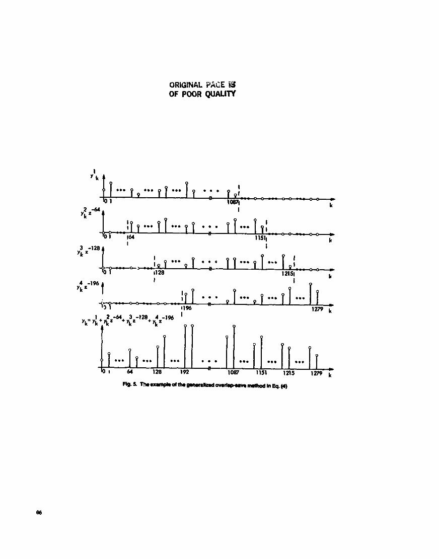
y, = y; + y: 2-64 + y; 2-128 + y; 2-192
= ( y; + y; 2-64) + (y; + y; 2-64) 2-128 (4)
The dationship between b,} and vk} for 1 b; i < 4 IS illus- trated in Fa. 5 Other cases of the generalired overlapsave method are constructed in a similar manner.
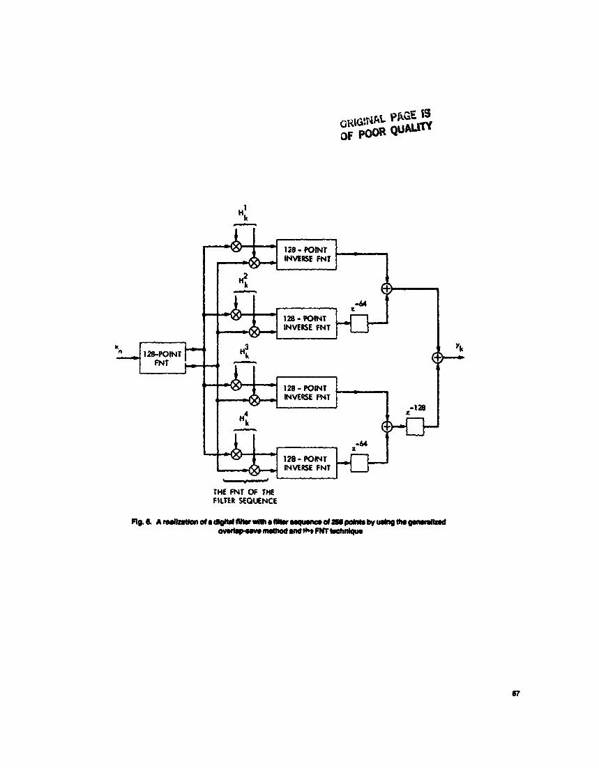
In Fa. 6 is shown the block diagram of an architecture for the generalized overlapsave method of a digital filter using one FNT and four inverse F N T s of 128 points. In this system the DIT and DIF techniques are used for the FNT and inverse MTs. resp?ccively. In the generalized overlap-save method, one of the two outputs of the inverse FNT butterfly in the last stage is not needed. Hence, the inverse FNT butte@ in the
IV. Conclusion A pipehe structun is dtotlopdd to compdllca 1-t
Fennat number W o r m . In this 1-t FNT, only addi- tiom and bit rotations are required. A barrel shiner Circuit fs modified to perform the multiplicatian of an integer by a power of 2 modulo a F e m t number. The overlap+ave method is generalized to compute tl.e lineat ionvolution of a @tal fdter with arbitrary input data and filter leaethg An
save method by a simple combination of one 12-t FNT and several inverse FNT structuns. lAig nalitrtim alleviates the dynamic ran@ limitations of tht FNTwith a lang trans- form length. The architecture is simple and r e p k , and hence suitable for Vzsl implementation.
architecture is developed to realize this genenlipd OQdap
2. AgamaL R C.. and Iturmg. C. S., "Fast coa*dution Udq Femut Number Tmw I H X lhns Aumstk. Sp& d
3. Agarwal, R C., rad Bums. C. S., "Number Ih##eolcal Trstwforms to Implecmt Fast Lbgital Convolution," ADc= EEE, Vd. 63. No. 4, pp. 550.560, Apd 1975.
4. NcQellan, J. H.. "Hardware Realization of A F e m t Number T d o n n , " tEEE
prras.Val.C-21,No. 12,pp. 1269-1273,Dsc. 1972.
fonns with Applkatioas to Mgital --,Val. ASS'-22, No. 2, p ~ . 87-97. A@ 1974.
b A&. d S@td -, Vd. ASP-24, No. 3, p ~ . 216-225, June 1976.
5. Luibowitz, L M., "A simplifkd Binuy Arithmetic For The knnat Number Trms- fom," lEEE A c o W ~ . spcad. eprd m, Val. ASP-24. No. 5. pp. 356359, Oct. 1976.
by Trms- forms Over A Finite Ficld," I D lhm Corpqptrcr~, Vol. C-26, No. 9, pp. 874-881, Sep. 1977.
7. M e r . C. M.. "On the Application of the Number Theoratic bkthods of High Speed Convolution to Two-Dimensionrl Filtering," I n 7hzn.s CYmiits and System, Vol.
6. Reed. 1. S.. Tmaq. T. K., Kwoh, Y. S.,and tkn, E. L, "ImpIp
CAS-22. Ncl 6. pp. 575. Junt 1975.
Finite Field Transfonns." IEEE 7hm on Nuclsar Scimx, Vol. NS24, No. I , Feb. 1977.
of Reedsolomon Codes Using F e m t Number Transf~nns," IEEE l h m I?$omafkm ?7nmy, Vol.
IO. Roots, H. F. A., and Best, M. R. "Concatearted Codiq on a Spacecraft-to-Cround
I I . Mead. C. A.. and Conway. L A., ktmdkction to VLSI System, Addison-Welsty,
12. Reed, 1. S.. and T ~ o n g . T. K.. The Use of Finite Field to Compute Convolutions,"
13. Rabiner. L. R.. and Gold. B.. Theory and Apphcation of Wtal Signal Proassing.
8. Reed. I. S.. K-h, Y. S.. T m , T. K., and lid. E. L, "X-Ray W t W t i O n by
9. Reed. 1. S.. Tn~mg, T. K.. and Welch. L R, "he Fast
IEEE lhma I ~ $ o w ~ ~ u Throry, VOI. IT-21. NO. 2. pp. 208-213, Motch 1975.
ht ice-Hal i . Inc.. E h g l e w d Cliffs, New Jersey, 1975.
ORMlMaL PAQE fs OF POOR QUALITY
64
ORIGINAL PAGE 1s OF POOR QUUW.
- *2 +2 +2 +2 +2 +2 CLOCK - c ; r : -; -
COUNTER COUNTER COUNTER COUNTER COUNTER COUNTER
-1
I '6
I ss
1 54
I s3
I s2
I Fig.4. A6rb0 .upcount r rd to~t ) l rcon801s lgnabS;r InRg. 1
ORlGMAL PALE OF POOR QUALIW
1 y k 4
I 0 .. ... 00 . 0 . .
.. k 0 1
I
128 - POMT INMRSSL FNT
128 - POINT
-1 28
4- THE FNT OF THE FILTER SEQUENCE
Appendix
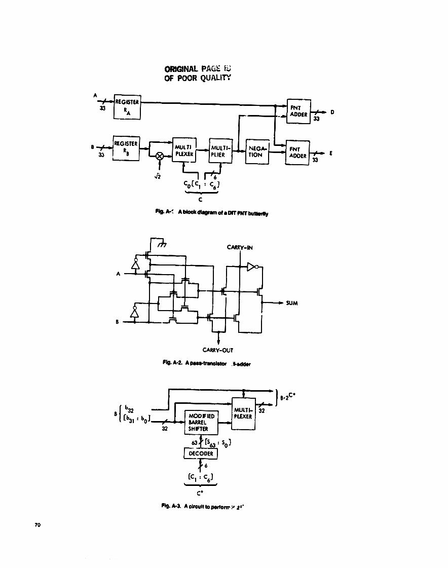
In this appendix a circuit Is d-ed to implement a DIT FNT butterfly shown in FQ. 2. A similar DIF FNT butterfly was designed in Ref. 4. To efficiently perform the FNT, num- ber representations have been proposed (Refs. 4.5) for binary arithmetic operations modulo F,. The diminished-1 represen- tation proposed by Liebowitz (Ref. 5 ) is wed in the following design. Let A be represented by [ ~ 3 2 uJ1 . . . u, u o ] , where 0 < A G 2,2 and a, is the ith bit of A. Table A-1 shows the correspondence between decimal numbers in a normal binary representation and their values in the diminished-1 representa- tion. The most significant hit (MSB) u , ~ can be viewed as the zero-detection bit in the diminished-1 representation.
Two basic binary arithmetic operations modulo f-, with (II = f l a r e addition and multiplication by a power of 2. Other operations can be expressed in terms of these two operations. In the following, some dz;& of these operations are described briefly. More specifics can be found in Ref. 5.
Addition: Let S = A t 8. IfA = 0, thenS= B. If B i O , then S = A. If neither A nor B equals 0, add [ujl ujO . . . u1 uo] and [b3, b30 . . . b , b o ] . Then com- plement the carry and add it to the previous sum. This yields S. Multiplication by a power of 2: Let B = A 2=. If A = 0, then B = 0. If A Z 0, left rotate [uol uJt . . . u1 uo] C bit positions, but complement the value of bit 31 when it is rotated to bit position 0, and set b,, = 0.
(3) Negation: Since 5 -1 (mod Fs), -A = A 2j2. Hence if A + 0, -A = [032 g31 r,,, . . . Zl 4 1 where 4 denotes the complement of u,. If A = 0, then -A = 0.
(4) Multiplication by fi Since a= Zz4 t 240, A 40 A 224 + A 0 240.
( 5 ) Multiplication by a power of fi Let B = A 0
If C is even, then B = A (2)cP. If C is odd, then B = ( A fi) 2(c-*)p,
In Fig. A-1 is shown a block diagram of an FNT butterfly shown in Fig. 2. In this design, A, B, D, and E are 33-bit data, and C is the 7-bit exponent nk in Eq. (1). Two realizations of an FNT adder can be found in Ref. 4. Figure A-2 shows a pass- transistor full-adder, which requires less silicon area. The mul- tiplier in Fig. A-l is used to multiply a number by a power of 2 modulo F, . Figure A-3 shows a block diagram of this multi- plier. The shifter in Fig. A-3 is a modification of a barrel shifter (Ref. 11) for performing bit rotation operations.
For purposes of illustration, consider the simple FNT over Fo = 2 + 1. In such an FNT butterfly the functional tabb and circuit of a modified barrel shifter are shown in Fig. A4, where the inputs are [b, bo) and [s, s2 s1 so], and the out- puts are [b; b i ] .