/V,5A N90. 18466 2O go TECHNIQUE FOR EVALUATING THE EROSIVE PROPERTIES OF ABLATIVE INTERNAL INSULATION MATERIALS J.C. McComb and J.M. Hitner California Institute of Technology, Jet Propulsion Laboratory Pasadena, CA 91109 ABSTRACT A technique for determining the average erosion rate versus Mach number of candidate internal insulation materials was developed for flight motor applications in 12 inch I.D. test firing hardware. The method involved the precision mounting of a mechanical measuring tool within a conical test cartridge fabricated from either a single insulation material or two non- identical materials each of which constituted one half of the test cartridge cone. Comparison of the internal radii , measured at nine longitudinal locations and between eight to thirty two azimuths, depending on the regularity of the ' erosion pattern before and after test firing, permitted calculation of the average erosion rate and Mach number. Systematic criteria were established for identifying erosion anomalies such as the formation of localized ridges and for excluding such anomalies from the calculations. The method is discussed and results presented for several asbestos-free materials developed in-house for the internal motor case insulation in solid propellant rocket motors. INTRODUCTION Beginning in July of 1986, the Solid Propulsion Technology Group at the California Institute of Technology's Jet Propulsion Laboratory began the in-house development of asbestos-free internal insulation materials as possible replacements for the asbestos-silica-nitrile/butadiene rubber formulation now used to insulate the internal casing of the Shuttle SRM. Initial efforts were directed toward the design and fabrication of scaled-down motor hardware for conducting the test firing of candidate asbestos-free insulation materials under conditions of temperature and pressure close to those currently experienced in the Shuttle SRM. Subsequent to the construction and testing of the motor hardware, a mechanical measuring tool was developed for the purpose of quantitating the erosion rate of insulation materials at Mach number levels similar to those found in the full-scale SRM. Because of the desire to test candidate materials under conditions that simulate the environment of the current SRM system as closely as possible, the studies initially utilized the same propellant formulation currently used in the Shuttle SRM's (PBAN/86% solids). In November of 1987, however, JPL switched to a nominal HTPB type propellant formulation now planned for use on the Advanced Solid Rocket Motor (ASRM), which is expected to replace the ' SRM sometime in the mid 1990's. In addition, JPL expanded its efforts to fabricate insulation test cones from two materials rather than just one candidate material in order to increase the number of materials which could be evaluated within the specified cost and time constraints allotted to the program. This paper presents the details of this straightforward and cost-effective technique for quantitating the erosion rate of internal insulation materials in small scale rocket motors. Although the technique has wide applications in the development of other rocket propulsion systems and propellant formulations, the work included here is focused on characterizing the erosive properties of asbestos-free insulation materials in solid propellant systems similar to the Shuttle SRM. EQUWMENT AND PROCEDURES TEST MOTOR DESCRIPTION - A cross-sectional diagram illustrating the ballistic test evaluation system (BATES) motor hardware used in this study is presented in figure 1. The primary test chamber has a 12 inch inside diameter and a length of 60.6 inches. Two cartridge loaded radial burning propellant grains are inserted into the forward end of the chamber. The grain web is * The research described in this paper was carried out by the Jet Propulsion Laboratory. California Institute of Technology, under a contract with the National Aeronautics and Space Administration. Approved for public release, distribution is unlimited. 83 https://ntrs.nasa.gov/search.jsp?R=19900009150 2019-02-03T23:35:58+00:00Z
Transcript
/V,5A
N90. 18466 2O
go TECHNIQUE FOR EVALUATING THE EROSIVE PROPERTIES OF ABLATIVE INTERNAL INSULATION
MATERIALS
J.C. McComb and J.M. Hitner California Institute of Technology, Jet Propulsion Laboratory
Pasadena, CA 91109
ABSTRACT A technique for determining the average erosion rate versus Mach number of candidate
internal insulation materials was developed for flight motor applications in 12 inch I.D. test firing hardware. The method involved the precision mounting of a mechanical measuring tool within a conical test cartridge fabricated from either a single insulation material or two non-identical materials each of which constituted one half of the test cartridge cone. Comparison of the internal radii , measured at nine longitudinal locations and between eight to thirty two azimuths, depending on the regularity of the ' erosion pattern before and after test firing, permitted calculation of the average erosion rate and Mach number. Systematic criteria were established for identifying erosion anomalies such as the formation of localized ridges and for excluding such anomalies from the calculations. The method is discussed and results presented for several asbestos-free materials developed in-house for the internal motor case insulation in solid propellant rocket motors.
INTRODUCTION Beginning in July of 1986, the Solid Propulsion Technology Group at the California Institute
of Technology's Jet Propulsion Laboratory began the in-house development of asbestos-free internal insulation materials as possible replacements for the asbestos-silica-nitrile/butadiene rubber formulation now used to insulate the internal casing of the Shuttle SRM. Initial efforts were directed toward the design and fabrication of scaled-down motor hardware for conducting the test firing of candidate asbestos-free insulation materials under conditions of temperature and pressure close to those currently experienced in the Shuttle SRM. Subsequent to the construction and testing of the motor hardware, a mechanical measuring tool was developed for the purpose of quantitating the erosion rate of insulation materials at Mach number levels similar to those found in the full-scale SRM.
Because of the desire to test candidate materials under conditions that simulate the environment of the current SRM system as closely as possible, the studies initially utilized the same propellant formulation currently used in the Shuttle SRM's (PBAN/86% solids). In November of 1987, however, JPL switched to a nominal HTPB type propellant formulation now planned for use on the Advanced Solid Rocket Motor (ASRM), which is expected to replace the
' SRM sometime in the mid 1990's. In addition, JPL expanded its efforts to fabricate insulation test cones from two materials rather than just one candidate material in order to increase the number of materials which could be evaluated within the specified cost and time constraints allotted to the program.
This paper presents the details of this straightforward and cost-effective technique for quantitating the erosion rate of internal insulation materials in small scale rocket motors. Although the technique has wide applications in the development of other rocket propulsion systems and propellant formulations, the work included here is focused on characterizing the erosive properties of asbestos-free insulation materials in solid propellant systems similar to the Shuttle SRM.
EQUWMENT AND PROCEDURES TEST MOTOR DESCRIPTION - A cross-sectional diagram illustrating the ballistic test evaluation system (BATES) motor hardware used in this study is presented in figure 1. The primary test chamber has a 12 inch inside diameter and a length of 60.6 inches. Two cartridge loaded radial burning propellant grains are inserted into the forward end of the chamber. The grain web is
* The research described in this paper was carried out by the Jet Propulsion Laboratory. California Institute of Technology, under a contract with the National Aeronautics and Space Administration.
Approved for public release, distribution is unlimited.
nominally 4.00 inches; total propellant weight is approximately 229 lbs. per motor. The head end of the forward grain is inhibited; all other grain surfaces burned completely upon ignition. The grain design provides for an average chamber pressure (Pc) of 625 psia, and the web burn time varied from 12.6 to 13.0 seconds, contingent on the specific propellant formulation used. The target motor chamber pressure was achieved by appropriate sizing of the nozzle throat di ameter
The key element of the insulation test motor consists of the insulation test cartridge located immediately downstream of the two propellant grains. The insulation test cartridge incorporates a truncated cone which constitutes the insulation test specimen. The entrance and exit diameters of the cone were sized relative to the nozzle throat to provide an initial Mach number range of approximately 0.035 to 0.40 at ignition. This cartridge configuration allows erosion data to be obtained over a wide range of Mach numbers during each test firing.. The aft end of the aft grain was flared to insure even flow into the entrance of the test cartridge throughout its burn time.
The nozzle assembly was mounted immediately aft of the insulation test carthdge. The throat insert entrance butts up against, and is faired smoothly with, the exit diameter of the insulation test cone to ensure smooth gas flow. The main body of the nozzle assembly was made of a compression molded half-inch long chopped glass fiber/phenolic material. The throat insert was fabricated from HLM-85 graphite. Precision throat sizing was required to achieve consistent chamber pressure control from test to test.
A hot wire ignition system was used to ignite the motor. A short length of nichrome wire was spliced into the firing circuit and inserted into a small propellant bar which was attached to the center bore surface at the head end of the forward grain. The ignition wiring was routed internally through the chamber and out the nozzle throat. The nature of the ignition system design resulted in a motor ignition delay of approximately 3 seconds.
Motor test intrumentation was limited to pressure transducers and an accurate timing system. Three independent pressure measurements were made at the head end of the chamber using Taber transducers. The average of the three measurements , was used to document
HEAD END INHIBITOR - PUTTY
SHIMS I AS NEEDED)
HEAD PLATE AFT CLOSURE AFT GRAIN AFT CHAMBER MOTOR CHAMBER (4(30 SIL-NORM)
INSULATiON CARTRIDGE
L\ \\ FORVARD GRAIN PUTTY
/PORT 11) 1INSULATION MATERXAL
GRAIN SLEEVE PRESSURE TRANSDUCER
'-PROPELLANT/HOT WIRE IGNITION SYSTEM c_PUTTY INERT PROPELLANT -/ (Jpj \ BACK SIDE VENTING SLOT 14)
—0-RING SEAL 0-RING SEALS-i) — HEAD PLATE INSULATION THROAT INSERT-PRESSURE TRANSDUCER PORT (3) NOZZLE ASSY.
Fig. 1 Cross-sectional diagram illustrating the ballistics test evaluation' system (BATES) motor hardware configuration.
pressure vs. time information. A fourth Taber pressure transducer measured chamber pressure at the entrance of the test cartridge. This measurement was primarily utilized , as a back-up pressure reading and was not used in establishing the pressure history of each test. PROPELLANT FORMULATIONS USED - Two different types of ammonium perchiorate/aluminum composite propellant formulations were used to test fire candidate 'materials: one using polybutadienecoacry1onitrile-coacrylic acid (PBAN) and one, using hydroxy-terminated
84
Fig. 2 Erosion rate measuring tool and accessories.
polybutadiene (HTPB) as the binder system. The composition by weight percent of the ingredients used to make each propellant type is given in Table I. The propellant grains were formed by directly casting uncured propellant slurry (including curing agent) into cartridges fabricated from phenolic resin. The propellant grains were then cured and inserted into steel firing cases before use. The propellant was typically cured at 1400 F for approximately 10-14 days depending on which propellant formulation was used. FABRICATION AND CURING OF INSULATION TEST CONES - A long, hollow, male cone mandrel was developed to lay-up and cure candidate insulation material into the desired shape. All of the test cones used for the work described here were fabricated using uncured B stage polymeric type flat stock material with a nominal sheet thickness of 0.1 inches. Orange peel-shaped segments were cut from the uncured insulation sheet stock with a prescribed material orientation (calendering aligned either parallel or perpendicular to the direction of hot gas flow). During the cone lay-up process, the orange peel segments forming the first ply were placed on the mandrel with overlapping longitudinal seams in order to maintain material mechanical support on the mandrel. All subsequent longitudinal ply seams were solid butt points. After laying up ten plies (midway through the cone wall thickness), two thermocouples were placed onto the insulation surface 180° apart. The remaining ten plies were then applied one layer at a time to complete the basic lay-up. The buried thermocouples were used to monitor cure temperature and time of exposure to elevated temperature. Some materials required a warm-up or debulk phase prior to exposure to high temperature. Curing was typically conducted at temperatures between 300° and 340° F for a period of time that ranged from 1 to 3 hours. After the cone was cured, sample cubes were cut from the base end and surface Shore "A" hardness measurements were taken at the mid cone wall position to verify that the insulation cure was complete. The cones were then machined to the appropriate specifications and bonded into test cartridges containing inert propellant prior to use.
TABLE I COMPOSITION BY WEIGHT OF PROPELLANTS USED IN STUDY
PBAN (86% solids)
Ingredient name AP granular 200 tm AP ground 10 tm Al, S-392 Ferric Oxide PBAN DOA DER-331
Percentage by weight 48. 995 21. 000 16. 000 0.005
11.490 0.700 1.810
HTPB (88% solids)
Ingredient name AP granular 400 xm AP granular 200 tm AP ground Al, S-392 R-45M Alrosperse AO-2246 CuO2O2 HX-878 IPDI
DESCRIPTION OF THE MEASURING TOOL AND MEASURING PROCEDURES The mechanical tool developed in this study to measure the erosive properties of candidate
insulation materials consists of two main components: an insertable tool probe equipped with measuring pins and a pair of ring plates which attach to the forward and aft ends of the insulation cartridge and suspend the tool within the cartridge interior. A photograph of the tool probe and the ring plates is shown in figure 2. A diagram illustrating a cut-away view as well as top view, front view, and rear view perspectives of the measuring tool is presented in figure 3. The tool probe was all-aluminum in construction, except for the measuring pins which were manufactured from steel drill rod material. The tool has an overall length of 20.200 inches, with the triangular-shaped rear unit (which houses 5 of the probe's nine pins) having a width of 0.765 inches and length of 14.700 inches. The steel pins are the active elements used to measure the internal surface of the test cartridge. The front unit of the tool is a solid aluminum truncated cone 5.500 inches long which houses four measuring pins. Because of difficulties in accessing retaining screws for the pins located in the front unit, it was necessary to design this segment of the tool so that retaining screws for the front four pins could be accessed from the front of the tool. Thus, the angular positions of 3 of these four pins had to be offset 45° from the position of the remaining pin. All nine of the pins were placed at an angle of 100° from the center axis of the cartridge (10° from axis normal) in order that the extended pins measure the surface at an angle normal to the internal insulation surface.
Pin travel was measured using a Starrett dial depth gauge (#644 JZ) having a zero to three inch range and a precision of 0.001 inches. Measurements were made to determine the distance between the tooling micrometer measuring seats and the flattened base of each pin. Care was taken to ensure that the micrometer seats were perpendicular to the axis of pin travel and parallel to the internal insulation surface.
The tool retention bar positions the Tool inside the Test Cartridge at the desired angle. The bar has a notch at one end to indicate the angle being measured. The retention bar attaches to the tool snugly to the aft ring plate, and, at the opposite end, an attachment set screw secures the tool to' the forward ring plate centering/retention bar.
The aluminum ring plates, which secure the measuring tool within the test cartridge, have an outside diameter of 15.000 inches and an inside diameter of 11.995 inches - an I.D. which is identical to the I.D. of the steel motor hardware casing. Eight set screws placed at 45° increments around the ring circumference secure each ring plate to the test cartridge external surface. Centering is achieved by adjusting the set screws until the desired target micrometer settings are achieved at four micrometer measuring seats located on each of the two ring plates. The aft ring plate is equipped with eight 3/8" diameter pins extending from the plate at 45° circumferential increments. These pins ensure proper alignment of the tool at the desired azimuths.
The measuring procedure involved six sequential operations: 1. installation and centering of the aft and forward ring plates, 2. installation and fastening of the tool to the ring plates, 3. release and subsequent locking of the measuring pins, 4. removal of the tool, 5. micrometer measurements, 6. repetition of steps 1-5.
In the case of pre-fire measurements, a data set consisting of 144 measurements made at 72 individual locations (9 longitudinal locations x 8 azimuths; 2 measurements per location) was obtained as results. Some cones fabricated from baseline material (ASB-SI-NBR) were measured at only 56 locations within the cone, as they were test fired before two additional pins were introduced onto the measuring tool in November, 1987. Depending on the regularity of the erosion pattern encountered after test firing, post-fire data sets in addition to measurements taken at the initial 72 locations were obtained for some insulation cones (see below for the, criteria by which erosion regularity was assessed).
RESULTS DATA REDUCTION AND ANALYSIS - A cut-away drawing illustrating the measuring tools positioned inside an insulation cone and defining the parameters which were used to calculated the degree of material erosion is given in figure 4. Figure 4 specifies these parameters for pin•
86
ORIGINAL PAGE Is OF POOR QUALITY
20.EOO•
Fig. 3 Top view, front view, back view, and cut-away view of the measuring tool.
CENTERING RAR J CRIETER SEAT
MOTOR RINO PS.AIE
PHEN, IC CARTS loGE
SPRING LOAO PIN ISTATIal II TOOl. COlT
UEASIJ1INO TOOl. INS&LATIGI MATER IAI
GD - PIN LENOTH
CE MICROMETER SEAT TO TOOL CENTERLINE DIMENSION
ED - MICROMETER SEAT TO PIN BASE EROSION MEASLIREMENT
XC - TOOL MOTOR END TO PIN STAION CENTERLINE DIMENSION
Fig. 4 Cut-away detail of a single measuring pin station defining the parameters used in the calculation of erosion rate.
station one, but these definitions can be extended to all nine stations on the measuring tool. A spring-loaded pin of known length (BD) is released and allowed to extend to the material surface. The distance between the micrometer seat and the pin base (ED) is measured with a depth gauge.. Once data has been collected at all of the eight azimuthal increments, the average distance, EDave(i), as defined by:
U
EDave(i)
j=1
87
is calculated, where EDi is the th measurement at the th station of the measuring tool, and n is the number of measurements being averaged. Data for determining the value of EDave(i) were considered acceptable if two consecutive measurements for each azimuthal position at each axial station yielded results which matched within 0.004 inches. Data which did not match on consecutive measurements were repeated, until agreement within a tolerance of 0.004 inches was obtained.
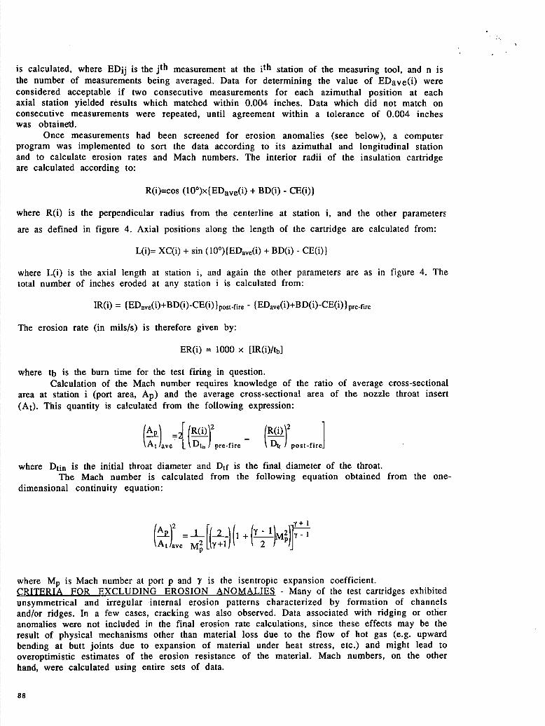
Once measurements had been screened for erosion anomalies (see below), a computer program was implemented to sort the data according to its azimuthal and longitudinal station and to calculate erosion rates and Mach numbers. The interior radii of the insulation cartridge are calculated according to:
R(i)=cos (lO°)x{EDave(i) + BD(i) - CE(i))
where R(i) is the perpendicular radius from the centerline at station i, and the other parameters
are as defined in figure 4. Axial positions along the length of the cartridge are calculated from:
L(i)= XC(i) + Sin (10°){EDave(i) + BD(i) - CE(i))
where L(i) is the axial length at station i, and again the other parameters are as in figure 4. The total number of inches eroded at any station i is calculated from:
The erosion rate (in mils/s) is therefore given by:
ER(i) = 1000 x [IR(i)/tb]
where tb is the burn time for the test firing in question. Calculation of the Mach number requires knowledge of the ratio of average cross-sectional
area at station i (port area, Ap) and the average cross-sectional area of the nozzle throat insert (At). This quantity is calculated from the following expression:
(A 2f(i)2 R(i)2
ave L pre-fire - D1 post-fire
where Dt is the initial throat diameter and D tf is the final diameter of the throat. The Mach number is calculated from the following equation obtained from the one-
dimensional continuity equation:
7+1 (A\2 1(\( At)ave M L+i)t k 2
where M is Mach number at port p and y is the isentropic expansion coefficient. CRITERIA FOR EXCLUDING EROSION ANOMALIES - Many of the test cartridges exhibited unsymmetrical and irregular internal erosion patterns characterized by formation of channels and/or ridges. In a few cases, cracking was also observed. Data associated with ridging or other anomalies were not included in the final erosion rate calculations, since these effects may be the result of physical mechanisms other than material loss due to the flow of hot gas (e.g. upward bending at butt joints due to expansion of material under heat stress, etc.) and might lead to overoptimistic estimates of the erosion resistance of the material. Mach numbers, on the other hand, were calculated using entire sets of data.
88
The degree of irregularity seen in the individual cones ranged from extensive to minimal; however, in all cases anomalous features were visible only in region where the average Mach number had exceeded 0.10 (pin stations 6-9). No statistically significant correlation was found between the degree of erosion irregularity and the amount of eroded material. The irregular features did appear to be reproducible, however, as second and third firings of the same material resulted in the same type of irregularity pattern being observed.
Data points were accepted or rejected on the basis of the relative spread in values obtained at each measurement station (each pin defining' one measurement stations). Ridges and channels were also identified by visual inspection during measurements, and these features were noted on the data sheets to assist in identifying erosion anomalies. The relative standard deviations calculated for post-fire radii taken at pin stations 1-5, where ridging or channeling effects were never visible, were found to range from 0.2 to 2 %. Introducing an anomaly (such as a ridge) having a magnitude of 100 milli-inchs or greater will increase the average relative error of that data point compared to points where no ridges exist from 0.2-2% to 4-6%, depending on which pin station encounters the ridge (the error is more pronounced at the higher number pin station where R(i) is at a minimum). Therefore measurements which differed from the largest measurement (the point at which the erosion was at a maximum) by 100 milli-inches or more (the equivalent of 2 or more standard deviations compared to data where no ridging occured) were systematically eliminated from the calculations.
Under circumstances where ridge 'points were noted by the cognizant engineer, but the difference between the maximum and minimum erosion measurement at a particular station was less than 100 milli-inches - a second procedure was followed. Careful comparisons were made between the magnitudes of each suspected ridge point, other angular measurements made at that particular station, and its axial neighbors. If a statistically significant error (one that is 2 standard deviations or greater) was found to exist between that data point and data points at lying at different angles but at the same longitudinal station, then points lying along the same azimuth but at one or more neighboring stations were examined in a similar fashion. If a statistically significant error (greater than 2 standard deviations) was found to exist between the neighboring stations and other azimuths lying at that longitudinal position, then that ridge point was rejected along with the neighboring axial data points, whether or not those additional points were noted as lying on a ridge by visual inspection of the cone. EROSION RATES FOR IN-HOUSE DEVELOPED AND BASELINE MATERIALS - Plots of erosion rate vs. Mach number for several test firings of baseline material and a few candidate materials are given in figure 5. The baseline material (Asbestos-Silica-NBR) was fired using both PBAN and HTPB propellant. Averages of the erosion rate calcdlated at a Mach numbers of 0.10 and 0.15 were found to be 21.0 ± 1.9 and 32.5 ± 3.1, respectively, for baseline material fired using PBAN propellant and 22.8 ± 1.0 and 36.0 ± 2.3 for baseline material fired using HTPB propellant.
Of the three material types tested other than Asbestos-Si-NBR, only Kevlar pulp-Si-EPDM was found to have erosion characteristics as good or better than the baseline material. Materials derived from cotton linters, oxidized polyacrylonitrile fiber (PAN), and Kevlar pulp suspended in butadiene-nitrile rubber (NBR) all failed to match or exceed the erosion resistance of the Asbestos-Si-NBR insulation.
DISCUSSION AND CONCLUSIONS The generally good agreement of erosion rate measurements made on the same material type
from firing to firing indicates that the measurement technique described above can provide reliable, informative, and accurate test data within reasonable time and cost limitations. The extent to which ridges and other erosion anomalies were formed appeared to depend on the calendering orientation of the insulation material within the cone, with material calendered perpendicular to the gas flow ridging more severely than material calendered in the direction of gas flow. Such anomolies, however, did not appear to have a direct impact on the measured rate of erosion. The erosion rate observed for baseline and other materials was slightly larger for materials fired using HTPB propellant as opposed to PBAN, probably because of the higher flame temperature and the greater output of erosive reaction products by the HTPB propellant.
Fig. 5 Erosion rate vs. Mach# plot for baseline material (Asbestos-Silica-NBR) and for two candidate internal insulation materials (see legend for individual material identities). Chamber pressure ranged from 613 to 626 psia, all firings used PBAN propellant except the third baseline firing; HTPB propellant was used for this firing.
The results included here also indicate that useful data can be obtained for test cones having a dual-material insulation configuration while maintaining a high degree of precision and accuracy within the measurements. The principle difficulty introduced by using a two-material insulation test cone seems to be the fabrication of the cone itself, as difficultly was encountered in some cases in getting mated materials to properly bond together and cure. The dual-material configuration also introduces limitations on the total surface area inside the cone which can be surveyed by this method, since boundary areas must necessarily be excluded from the data sample. In every case, however, it was possible to obtain sufficient information to accurately estimate the erosive properties of dual-material insulation cones without including. measurements taken at boundary areas.
Despite the marginal performance of all but one of the experimental insulation materials tested in comparison to the baseline material, the results demonstrate that viable asbestos-free internal insulation materials are feasible. Although the improvement observed for the Kevlar pulp-Si-EPDM insulation material developed in-house is not spectacular, it now seems a very likely possibility that new asbestos-free insulation materials can and will be developed for solid propellant systems in the near future.