Page 1
\N91-10305
AN ANALYTICAL SOLUTION FOR THE ELASTOPLASTIC RESPONSE OF
A CONTINUOUS FIBER COMPOSITE UNDER UNIAXIAL LOADING
Jong-Won Lee, Research Assistant
David H. Allen, Professor
Aerospace Engineering Department
Texas A&M University
College Station, Texas 77843
ABSTRACT
A continuous fiber composite is modelled by a two-element composite
cylinder in order to predict the elastoplastic response of the compos-
ite under a monotonically increasing tensile loading parallel to fib-
ers. The fibers and matrix are assumed to be elastic-perfectly plastic
materials obeying Hill's and Tresca's yield criteria, respectively. The
present paper investigates the composite behavior when the fibers yield
prior to the matrix.
INTRODUCTION
The elas_oplastic response of fibrous composites has been the subject of a
number of theoretical studies[l-4]. When a composite is subjected to uniaxial
tension loading parallel to the fibers, a two-element composite cylinder(Figure
l-a) has been frequently utilized to model the composite response. The loading
direction together with the axisymmetric geometry of the representative volume
element simplify the mathematical difficulties associated with the equilibrium
equations. By implementing a traction-free boundary condition to the outermost
surface of the representative volume element, it becomes possible to construct a
well-posed boundary value problem when the fibers and the matrix are assumed to
obey Hill's and Tresca's yield criteria, respectively. A closed form analytical
solution requires further simplifications such as elastic-perfectly plastic con-
stituents, perfect interfacial bonding, etc. When the composite constituents are
assumed to obey the modified yield criterion proposed by Hill[l], the hardening
effect of the matrix can be taken into account without mathematical difficul-
ties. However, the present study focuses on a composite with non-hardening con-
stituents.
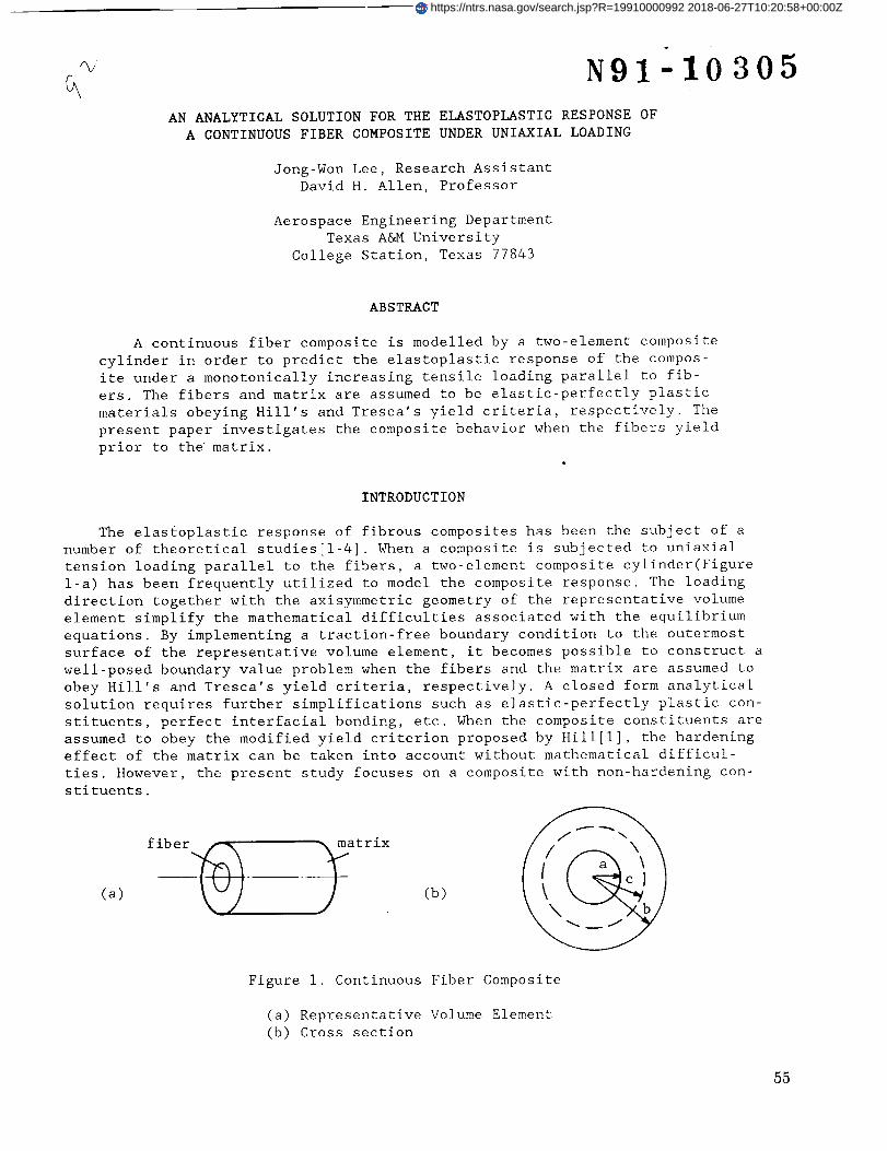
fiber _. _at rix(a) (b)
Figure I. Continuous Fiber Composite
(a) Representative Volume Element
(b) Cross section
55
https://ntrs.nasa.gov/search.jsp?R=19910000992 2018-06-27T10:20:58+00:00Z
Page 2
Hill proposed a relatively simple yield criterion which assumes the differ-
ence between the axial stress and the arithmetic mean value of the radial and
circumferential stresses to be equal to the yield stress[l]. When this yield
condition is implemented to a composite with elastic fibers surrounded by an
elastic-perfectly plastic matrix, the entire matrix yields simultaneously,
resulting in a discontinuity in the slope of the effective stress-strain curve.
Mulhern, Roger, and Spencer[2] proposed a rigorous analytical solution for a
two-element composite cylinder under cyclic loading. Their study models an elas-
tic core fiber surrounded by an elastic-perfectly plastic matrix tube obeying
Tresca's yield criterion. The resulting composite behavior is almost as bilinear
as Hill's solution. However, the slope of the effective stress-strain curve is
continuous because the plastically deformed matrix zone propagates from the
fiber -matrix interface to the outer surface of the matrix.
Ebert and Gadd[3] studied a similar problem for an elastic-perfectly plastic
core fiber surrounded by elastic matrix. Ebert, et al.[4] extended this to an
elastic-perfectly plastic matrix. However, the application of their numerical
solution is restricted to a composite in which the Poisson's ratios of the fiber
and the matrix are equivalent.
The present paper extends the study of Ebert and other authors[3,4] to a
two-element composite cylinder representing a transversely isotropic fiber sur-
rounded by an isotropic matrix in which the Poisson's ratios of the core fiber
and the matrix need not be identical.
MODEL FORMULATION
Consider a metal matrix composite reinforced by continuous fibers under uni-
axial tension loading parallel to the fibers. The globally averaged stress state
of the representative volume element is assumed to be one dimensional. The elas-
tic-plastic response of the bar can be analytically predicted by solving an
equivalent boundary value problem of a single core fiber which is perfectly
bonded to the surrounding matrix tube. The volume element representing the
equivalent boundary value problem is illustrated in Figure i. The uniaxial ten-
sion loading in the fiber direction produces a three dimensional stress state in
both the core fiber and the surrounding matrix. When the tension loading
increases monotonically, either the fiber or matrix yields at a certain magni-
tude of the applied tension loading. Further increment of the tension loading
induces the yielding everywhere in the composite. The possible yield sequences
for the composite constituents of the representative volume element can be cate-
gorized into three cases as shown in Figure 2. The present study provides ana-
lytical solutions to the first case under monotonically increasing tension load-
ing.
l
I CASE1 [
Ifiber yield
partial matrix yield
entire matrix yield
elastic fiber - elastic matrix I
! ,I I
partial matrix yield I I partial matrix yield
entire matrix yield I I fiber yieldfiber yield entire matrix yield
Figure 2. Possible Composite Yield Sequences
56
Page 3
The entire mathematical formulation of the present study is based on the
following key assumptions:
i. The core is assumed to be a transversely isotropic fiber surrounded by an
isotropic matrix.
2. Both constituents are assumed to be elastic-perfectly plastic.
3. The interfacial bonding between the core fiber and the matrix is assumed to
be perfect throughout deformation.
4. The core fiber is assumed to obey Hill's yield criterion.
5. The matrix tube is assumed to obey Tresca's yield criterion.
6. The axial strain is assumed to be spatially homogeneous.
Since the geometry of the representative volume element is axisymmetric and
the loading direction is parallel to the core fiber, the only non-trivial
equilibrium equation is
__ + - 0 (I)
r
The constitutive equations for the transversely isotropic core fiber and the
isotropic matrix are
• f p%
6 r -e r
If P I
eS-e 8 , =
_ffZ - £Z
I/E T -WTT/E T -WLT/E L-
-UTT/ET I/E T -VLT/E L
-WLT/E L -WLT/EL I/E L
• f.
(rr
f
f
_(rZ.
(2-a)
and
• m. .m p,arl i-_ m vm v m Cr-erl
ml
ml
_0 z )
m m
(l+wm)(l-2u m)
_m l-wm Wm
Wm Wm l-wm
m Pl• e_-esf (2-b)
respectively.
Since the plastic strain is incompressible,
P P Pe r + e_ + e z = 0 (3)
It can be shown that Hill's yield criterion becomes the following yield condi-
tion for the transversely isotropic core fiber under a transversely isotropic
loading:
f f f f
I az Or I = l°z °el = YL (4-a)
This mathematical expression is identical to Tresca's yield criterion.
57
Page 4
The surrounding matrix will yield according to one of the following conditions.
in m
[ °z - Or ] = Ym (A-b)
m m
] °'z - °_) ] = Ym (4-c)
m m m m
[ az er ] = ] az aO ] = Ym (4-d)
The external boundary conditions and interior compatibility are
a r = 0 at r = b
o r = unique at r = a or r = a, c
u r = 0 at r = 0
u r = unique at r = a or r = a, c
(5-a)
(5-b)
(5-c)
(5-d)
When both fiber and matrix responses are elastic, the stress state and the
displacement field in the representative volume element are determined by match-
ing the radial stress and displacement at the fiber-matrix interface. The prob-
lem solving procedure for this elastic deformation is simple and straightforward
as discussed below.
Since the stress state in the fiber is always transversely isotropic,
f f
o r = a_ = -P (6-a)
f
Oz = -2WLTP + ELCz (6-b)
where P is an unknown constant to be determined. The radial displacement in
the fiber is given by
u r = Clr (7-a)
The strain components become
f f
Cr = c_ = C 1 (7-b)
From (2-a),(6), and (7-b),
C I : -[(I-_TT-2VLTVTL)P/E T + WLT¢z]r (8-c)
Within the matrix,
m pa2 [ b2]o r = -- 1 --
b2_a 2 r 2
(9-a)
58
Page 5
m pa2 [ b2 ]o# 1 +--
b 2 _a 2 r 2
m 2Pum a2
a z + Emc zb2_a 2
m
u r = C2r + C3/r
The strain components become
(9 -b)
(9-c)
(10-a)
m
c r = Ur, r = C 2 C3/r 2 (lO-b)
m
c 8 = Ur/r = C 2 + C3/r 2 (lO-e)
From (5-a) and (5-b), C 2 and C 3 are determined as functions of P.
pa2(l+um)(l-2wm )
C 2 = _ VmC z
Em(b2-a 2 )
pa2b2(l+Ym)
C 3 =
Em(b2-a2)
ll-a)
ll-b)
Then the radial displacement in the matrix becomes
pa2(l+wm)
u r - [(l-2wm)r+b2/r] Wm_z <12)
Em(b2-a 2 )
The interracial stress in the radial direction, -P, is determined from
the displacement compatibility given by (5-d).
(Um- ULT ) _z-p =
A 1where
1-
WTT- _'LTWTL
A 1 =
E T
+ [l+ inl[a2 l-2 m+b2Ja2 --_--mJ b2 -a2
(13-a)
(13-b)
It can be shown that the effective axial Young's modulus of the volume element
is given by
E c = EL(a/b)2 + Em(b2-a2)/b 2 + 2<a/b)2(Wm-_LT)2/Al (14)
Under monotonically increasing axial strain, _z , either the core fiber or the
surrounding matrix yields first. The yield strains, strengths, and the Poisson's
ratios of the constituents govern the composite yield sequence. When the applied
axial strain reaches a certain value, Czy , the core fiber yields first if the
59
Page 6
longitudinal yield strength of the fiber is much smaller than the yield strength
of the matrix. The initial yield strain, ezy , at which the entire fiber yields
is given by
Y LL[ (_m-_LT) (i- 2VLT) ]ezy = 1 -
ELA 1 +(_m-_LT)(I-2_LT)
(15)
After the core fiber yields, the surrounding matrix behaves elastically
until matrix yield at the interface occurs. Since the plastic strain is incom-
pressible and the stress state is transversely isotropic in the core fiber,
stresses, total strains and plastic strains in the fiber become
f f f
ar = a8 = -P, az = -P + YL (16-a)
P P PCr = E0 = -(z/2 (16-b)
f f f f
_r = (# = Ur,r = Ur/r (16-c)
where -P is the unknown interfacial stress to be determined.
f f f
The first strain invariant, Er+_0+Cz, together with the uniqueness of the
radial displacement at the material interface determine the magnitudes of the
fiber stress components as functions of the applied axial strain. During this
strain increment where the matrix still deforms elastically, the stress compo-
nents and the radial displacement in the matrix given by equations (9-a), (9-b),
and (9-c) are still valid if the interfacial stress in the radial direction is
redefined as
P
where
71 =
-_I_2 [ YE_LJ(l-2wm)Cz-(l-2WLT)
NI+2_2
E m (b2-a2)/a 2 ]
1+_ m _1 ---_m_(b/--_ 2J
(17-a)
(17-b)
E T
_2 = (17-c)
2-2VTT-4VTL+VTL/ULT
The radial displacement in the fiber becomes
F [ 1f Um_l+_2 (I-2ULT)_2 YL
u r = - Ez r + -- -- r
L_I+2_2 _i+2_2 J EL
(18)
Further increase of the applied axial strain causes yielding of the matrix
material. The plastically deformed region then propagates toward the outer sur-
face of the matrix. During this strain increment, the elastically deformed mat-
60
Page 7
rix and the plastically deformed matrix exist together as shown in Figure l-b.
Outside the interface between the plastic matrix and elastic matrix, the stress
state and deformation are given by the elasticity solution with an unknown
internal pressure, P*, acting on the interfacial surface between the plastic
matrix and elastic matrix. Therefore, within the elastically deformed matrix,
m 2P*vm c2
O Z
b2_c 2+ EmE z
(19-a)
(19-b)
(19-c)
m
u r =
p*c2(l+vm )
Em(b2-c2 )
[(l-2vm)r+b2/r] Vm(zr
where P* is determined from Tresca's yield criterion given below.
(20)
At r = c,
Then,
p* =
I m m
]°z-ar] = Ym , for Vm>VLT (21-a)
m m
]°z-°#] = Ym , for Vm<VLr (21-b)
(Ym°Em(z)(b2-c2)/c 2
2v m (b2+c2)/c 2
(22)
where c is an unknown function of the applied axial strain, _z"
Within the plastically deformed matrix, Tresca's yield criterion given by
eqs. (21-a) and (21-b) determines the stress state and displacement field. If
the Poisson's ratio of the matrix is smaller than that of the fiber, the fiber-
matrix interfacial stress in the radial direction is always tensile. On the
other hand, when the Poisson's ratio of the matrix is greater than that of the
fiber, the fiber-matrix interfacial stress may be either compressive or tensile.
After the core fiber deforms plastically, the apparent Poisson's ratio of the
fiber approaches 0.5 as the applied axial strain increases. The interfacial
stress in the radial direction may be changed from compressive to tensile before
the initiation of matrix yield. If the matrix yield strain is far greater than
that of the core fiber, the interfacial stress in the radial direction at the
onset of matrix yield becomes tensile. Then, from eq. (3) and (4-c),
P P PE r = O, _# = -_z (23)
m m m Em m m m
a# + o z = 200 + Ym = (2VmCr + _0 + Ez) (24)
(l+vm)(l-2v m)
61
Page 8
From eq. (24) and the strain-displacement relationships, the radial and circum-
ferential stresses are expressed in terms of the radial displacement and its
gradient with respect to r.
m Em m m m
o r = [(l-_m)Ur, r + _mUr/r + _m_z] (25-a)
(l+vm)(l-2_ m)
m Em/2 m m m
o_ = (2WmUr, r + Ur/r + Cz) - Ym/2 (25-b)
(l+vm) ( i - 2_m)
The equilibrium equation thus becomes
2 m m m2(l-um)r Ur,rr + 2(l'um)rUr,r Ur = -r(l-2_m)[(l+um)Ym/Em ez] (26)
The solution to the above differential equation is given by
m
u r = -[(l+vm)Ym/E m Ez]r + c2rk + C3 r-k (27)
where
k = [2(l-vm)]-I/2
Since the radial stress and displacement must be single-valued at r=c and
r=a, the unknown constants are determined as
-(l+vm)(Emcz-Ym)b2c-(k+l)
C 2 = (28-a)
kEm(l-2_m+b2/c 2 )
(l+vm)(Em(z-Ym)b2c(k-l)
C 3 = (28-b)
kEm(l-2vm+b2/c2)
The radius of the matrix yield front, c, can also be determined as a function of
the applied axial strain, Ez, and material properties. However, it is more
convenient to express the applied axial strain as a function of the radius of
the matrix yield front by satisfying the uniqueness of the radial displacement
at the fiber-matrix interface. Until the yield front reaches the outermost sur-
face of the matrix tube, the axial strain is given as
E Z
where
Ym
Em
Ym YL
(l-2_m)__ - (I-2WLT)_
Em E L
l-2um+2@2(l+um)-
Em41
_2(I-2_m)
(29-a)
62
Page 9
(b/c)2[(l-vm+_m/k)(a/c)(k-l)+(l-_m-_m/k)(a/c) -(k+l) ]
_i = I (29-b)i - 2_m + (b/c) 2
(b/c)2[(a/c)(k-l)-(a/c)-(k+l)]/k
_2 = i (29-c)
i 2_m + (b/c) 2
After the entire matrix yields, it can be shown that eqns. (28-a) and (28-b)should be corrected for further axial strain increment as
C2 =
i-(l-2_2/_2)(a/b)-(k+l)I-2_ m
3N2](Emcz-ym)
EmJ
_3
_la(k-l)[(l-2_2/_2)(a/b) -2k (i-2_2/_i) ]
30-a)
C3 =
- (Em_z-Ym) - _3
I -2_ m EmJ
_2a-(k+l)[(l-2_2/_l)(a/b) 2k - (I-2_2/_2) ]
30-b)
_I =
Em[um+(l-um)k]
(l+vm)(l-2_ m)
30-c)
Em[_m-(l-vm)k]
=2 = (BO-d)
(l+um)(l-2v m)
Ym_2 [ YLEm]_3 = -- l-2um- (I-2VLT)--
Em ELY m
(30-e)
Then the stress components in the matrix become"
m Em_z-Ym
_r = + _IC2 r(k-l) + _2C3 r-(k+l) (31-a)
1 - 2_ m
m EmEz-Ym Em[(_mk+i/2)C2r(k-l)-(_mk-I/2)C3r-(k+l)]
a8 = + (31-b)
I-2_ m (l+_m)(l-2_m)
m m
a z = a# + Ym (31-c)
Further increase of the axial strain, as mentioned in ref. [2], may cause
another type of plastically deformed matrix region in which the radial and cir-
cumferential stresses are identical. The present paper, however, does not con-
sider this case because the infinitesimal strain assumption may not be valid for
further increase of the applied axial strain.
63
Page 10
RESULTS AND DISCUSSION
The effective stress-strain curve for a composite cylinder can be predicted
by calculating the average value of the axial stress, _z, as a function of the
applied axial strain, _z, and the mechanical properties of the composite
constituents. As an example, the effective stress-strain curve of the composite
studied by Ebert, et al.[4] is demonstrated in Figure 3. The mechanical proper-
ties of the composite constituents appear in Table I. In Figure 3, the solid
lines represent the present analysis. Within the straight line segment(OA), both
the core fiber and the surrounding matrix tube are within their elastic limits.
When the applied axial strain reaches _zY, the entire core fiber yields. The
next line segment(AB) represents the hardening behavior of the composite with
plastically deformed core surrounded by an elastic tube. When the applied axial
strain reaches Ezl in the same figure, the surrounding matrix starts yielding
from the fiber-matrix interface. This strain can be calculated from eq. (29-a)
by setting c=a. Then the plastically deformed matrix region propagates outward
until the entire matrix tube yields. This smooth transient region is represented
by the line segment BC. The applied axial strain, _z2, where this transient
phenomenon terminates can be calculated from the same equation by setting c=b.
The composite response to further axial strain increase then follows the remain-
ing line segment. Within the transient region and for the higher value of the
applied axial strain, the matrix tube material is assumed to be nonhardening
even though the material hardens significantly(Figure 3 in ref. 4). The exper-
imental results of Ebert, et al.[4] are also plotted in the same figure.
Table i. Constituent Properties the Composite[4]
Ultimate 0.05_ Elastic Poisson's
Materlal Strength Offset Yield Modulus ratio
(Ksi) (Ksi) (Msi)
SAE 4140 93 54.9 28.7 0.29
(Core)
Maraging Steel 318 288 25.5 0.29
(Matrix Tube)
In Figure 4, the radial variations of the radial, circumferential and axial
stresses in the composite cylinder of which the core volume fraction is 0.5 are
plotted for two distinctive axial strain values, _zl and Cz2. The stresses in
the core material decrease slightly as the axial strain increases from Czl. At
the onset of the initiation of the matrix yield, the axial stress in the matrix
tube is cDnstant. As the applied axial strain increases beyond _zl, the axial
stress in the matrix has its maximum value at the free surface.
64
Page 11
200000 -
m 150000
,--qlO0000
50000-
0 ,0.0170
fiber volume frecUon = 0,5
/i/"s
PRESENT SOLUTION_CbJ=, REF. 4EXPERI_3_D_, REF. 4
i j , i , , i i I i0.005 0.010 '0.015
Applied Axial Strain
200000
150000"
[/]
,--_ 100000
I_O 50000
0o.0(1o
fiber volume fraction = 0.455
/ _ PRESENT SOLUTION/ --- NUMERICAL, REF. 4
..... EXPERIMENTAL, REF. 4i i i 1 I ' i i i I i , i i
0.005 0.010 0.015
Applied Axial Strain
Figure 3. Composite stress-strain curve
3oo00o
200000
"_ 100000
03
-1000000.0
E ---- ,E'zl 0"=
0.'2 o._ o.'6(r/b)
,......_.___a_I
I
G,$
300000
200OOO
m
"_" 100000
r_
-1OOO0O!
0.8 1.0 0.0
---- £z2 0"1;
II
I..........
ff.o
0.'2 ' o._ o.'8 ' o.'8 1.o(r/b)
Figure 4. Stresses in the composite
65
Page 12
CONCLUSIONS
The present study provides an analytical prediction of the elastoplastic
response of continuous fiber composites with weaker fibers. The incremental form
proposed by Ebert, et al.[4] must be replaced by the second order ordinary dif-
ferential equation given by eq. (26). Furthermore, the present analysis can
handle the mismatch of the PoissonSs ratios as well as transversely isotropic
fibers. The present analysis will be generalized for the same type of compos-
ites under cyclic loading for providing a comparison to the study of Mulhern, et
al.[2]
REFERENCES
i. Hill, R., "Theory of Mechanical Properties of Fibre-Strengthened Materials:
II. Inelastic Behavior," J. Mech. Phys. Solids, Pergamon Press Ltd., Vol.
12, pp. 213-218, 1964.
2. Mulhern, J. F., Rogers, T. G., and Spencer A. J. M., "Cyclic Extension of an
Elastic Fiber with an Elastic-Plastic Coating," J. Inst. Maths Applics,
Vol. 3, pp. 21-40, 1967.
3. Ebert, L. J. and Gadd, J. D°, "A Mathematical Model for Mechanical Behavior
of Interfaces in Composite Materials," Fiber Composite Materials, Papers
Presented at a Seminar of the ASTM, October 17-18, 1964, pp. 89o113.
4. Ebert, L. J., Hecker, S. S., and Hamilton, C. H., "The Stress-Strain Behavior
of Concentric Composite Cylinders," J. Composite Materials, Vol. 2, No. 4,
pp. 458-476, Oct. 1968.
66