N95- 14070 CLEAN ASSEMBLY AND INTEGRATION TECHNIQUES FOR THE HUBBLE SPACE TESLESCOPE HIGH FIDELITY MECHANICAL SIMULATOR David W. Hughes Swales and Associates, Behsville MD Randy J. Hedgeland NASA Goddard Space Flight Center ABSTRACT A mechanical simulator of the Hubble Space Telescope (HST) Aft Shroud was built to perform verification testing of the Servicing Mission Scientific Instruments (Sis) and to provide a facility for astronaut training. All assembly, integration, and test activities occurred under the guidance of a contamination control plan, and all work was reviewed by a contamination engineer prior to implementation. An integrated approach was followed in which materials selection, manufacturing, assembly, subsystem integration, and end product use were considered and controlled to ensure that the use of the High Fidelity Mechanical Siumulator (HFMS) as a verification tool would not contaminate mission critical hardware. Surfaces were cleaned throughout manufacturing, assembly, and integration, and re- verification was performed following major activities. Direct surface sampling was the preferred method of verification, but access and material constraints led to the use of indirect methods as well. Although surface geomctrics and coatings often made contamination verification difficult, final contamination sampling and monitoring demonstrated the ability to maintain a class M5.5 environment with surface levels less than 400B inside the HFMS. INTRODUCTION It has been well established within the contamination control community that clean assembly and integration arc essential elements in the creation of a clean test or manufacturing facility. This principle applies to aerospace Icst equipment (also called ground support equipment, or GSE) because of the large size and complex intcraction of thc GSE with flight hardware; cross contamination of sensitive thermal and optical surfaces can cause delctcrious cffccts. An alignment and envelope vcrification tool, the HFMS, was built for the HST Servicing Missions. Thc HFMS was manufactured, assembled, and tested within the cleanliness constraints imposed by the HST contamination control program for use with contamination scnsitivc Scientific Instruments (Sis). This paper reports on the unique contamination problems associated with creating a mock-up of a largc structurc for use in testing sensitive hardware. Thc HFMS and its cleanliness requirements will be dcscribcd, and the approach to HFMS contamination control will be presented. The practical aspects of implementing this approach and some lessons learned during the construction and certification of the HFMS will be discussed. HIGH FIDELITY MECHANICAL SIMULATOR Pinysical Description The HFMS is a mechanical mock-up of the HST Aft Shroud and contains a support system for 5 Sis, 3 Fine Guidance Sensors, electrical harnesses, thermal blankets, and an equipment shelf for electronics. The HFMS is compriscd of four major parts. The Aft Shroud Mock-up (ASM), a 5 meter high, 5 meter diameter cylinder, supports thc Main Ring Simulator (MRS) (Figure 1). In the HST, the Primary Mirror is supported by the Main Ring (Figure 2). Suspcndcd from the MRS is the Focal Planc Dcck (FPD) and Scientific Instrument Support Structure (SISS) (Figure 3). Light collected by the HST is directed into SI apertures in the Hub area of the FPD. Access to the SISS is through three sets of doors in the ASM; an opening above one of these doors provides access into the FPD for a radial SI. Threc sets of doors allow access to the other radial bays. Within these bays are guiderails and latches for insertion and capturc of Sls. As a "high fidelity" simulator, the interior finish and astronaut interfaces have the samc appcarancc and function as 99 PAGE BLANK NOT FILMED https://ntrs.nasa.gov/search.jsp?R=19950007657 2018-08-29T06:59:21+00:00Z
Transcript
N95- 14070
CLEAN ASSEMBLY AND INTEGRATION TECHNIQUES
FOR THE HUBBLE SPACE TESLESCOPE
HIGH FIDELITY MECHANICAL SIMULATOR
David W. Hughes
Swales and Associates, Behsville MD
Randy J. HedgelandNASA Goddard Space Flight Center
ABSTRACT
A mechanical simulator of the Hubble Space Telescope (HST) Aft Shroud was built to perform verification testing ofthe Servicing Mission Scientific Instruments (Sis) and to provide a facility for astronaut training. All assembly,
integration, and test activities occurred under the guidance of a contamination control plan, and all work was reviewed
by a contamination engineer prior to implementation. An integrated approach was followed in which materials
selection, manufacturing, assembly, subsystem integration, and end product use were considered and controlled toensure that the use of the High Fidelity Mechanical Siumulator (HFMS) as a verification tool would not contaminate
mission critical hardware. Surfaces were cleaned throughout manufacturing, assembly, and integration, and re-
verification was performed following major activities. Direct surface sampling was the preferred method of verification,but access and material constraints led to the use of indirect methods as well. Although surface geomctrics and
coatings often made contamination verification difficult, final contamination sampling and monitoring demonstrated the
ability to maintain a class M5.5 environment with surface levels less than 400B inside the HFMS.
INTRODUCTION
It has been well established within the contamination control community that clean assembly and integration arcessential elements in the creation of a clean test or manufacturing facility. This principle applies to aerospace Icst
equipment (also called ground support equipment, or GSE) because of the large size and complex intcraction of thc
GSE with flight hardware; cross contamination of sensitive thermal and optical surfaces can cause delctcrious cffccts.
An alignment and envelope vcrification tool, the HFMS, was built for the HST Servicing Missions. Thc HFMS was
manufactured, assembled, and tested within the cleanliness constraints imposed by the HST contamination control
program for use with contamination scnsitivc Scientific Instruments (Sis).
This paper reports on the unique contamination problems associated with creating a mock-up of a largc structurc for
use in testing sensitive hardware. Thc HFMS and its cleanliness requirements will be dcscribcd, and the approach to
HFMS contamination control will be presented. The practical aspects of implementing this approach and some lessonslearned during the construction and certification of the HFMS will be discussed.
HIGH FIDELITY MECHANICAL SIMULATOR
Pinysical Description
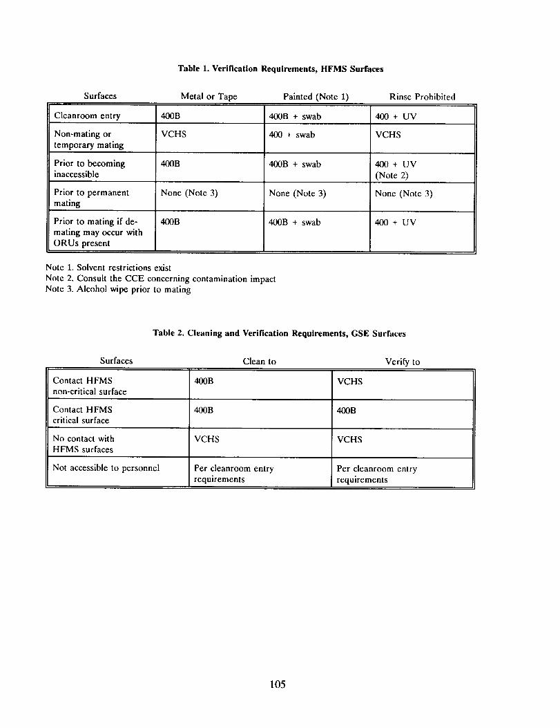
The HFMS is a mechanical mock-up of the HST Aft Shroud and contains a support system for 5 Sis, 3 Fine GuidanceSensors, electrical harnesses, thermal blankets, and an equipment shelf for electronics. The HFMS is compriscd of four
major parts. The Aft Shroud Mock-up (ASM), a 5 meter high, 5 meter diameter cylinder, supports thc Main Ring
Simulator (MRS) (Figure 1). In the HST, the Primary Mirror is supported by the Main Ring (Figure 2). Suspcndcd
from the MRS is the Focal Planc Dcck (FPD) and Scientific Instrument Support Structure (SISS) (Figure 3). Light
collected by the HST is directed into SI apertures in the Hub area of the FPD. Access to the SISS is through three sets
of doors in the ASM; an opening above one of these doors provides access into the FPD for a radial SI. Threc sets ofdoors allow access to the other radial bays. Within these bays are guiderails and latches for insertion and capturc of
Sls. As a "high fidelity" simulator, the interior finish and astronaut interfaces have the samc appcarancc and function as
In order to understand the sequential imposition of contamination constraints, the HFMS developmental stages must
be delineated. The HFMS was assembled and integrated at Goddard Space Flight Center (GSFC). Certain
subassemblies were received from the manufacturer already assembled; these were the FPD, the MRS, and the ASM.
Other parts were fabricated at GSFC and transferred to the Spacecraft Systems Development and Integration Facility(SSDIF) for assembly. The SSDIF is a class M5.5 cleanroom capable of supporting the integration of two Shuttlc
payloads concurrently. Integration of the HFMS began with disassembly and cleaning of the MRS, and mating of thc
MRS with the FPD. After SI latches were installed and aligned on the FPD, the SISS was added to the assembly.Again, latches wcrc installcd, and alignment and metrology verification activities occurred. The cquipmcnt shelf and
blankets were added to the structure, and the structure was integrated with the ASM. Cables were routed and final
blanket closcout was performed. A significant milestone in the contamination control program was the integration of
Ihe HFMS intcrior parts with the ASM. This integration virtually eliminated access to the Hub area, and greatlyrcslrictcd access to the FPD and MRS underside. As access to various surfaces became more restricted, the
contamination requirement became more stringent.
Requirements
The contamination rcquiremcnts are derived from the intended uses of the HFMS: envelope verification of Sis,
astronaut familiarization with HST interfaces and Orbital Replacement Unit (ORU) installation, SI confocality and
alignmcnt verification, and S1 thermal vacuum operational tests. The intimate contact between the Sis and the HFMS
imposes a surface clcanlincss requirement upon the HFMS interior equal to the most stringent of the SI externalsurface requirements: Level 400B per Mil-Std 1246. Contact between the astronauts and the exterior surfaces of the
i tFMS provides the opportunity for cross contamination of the interior during crew familiarization; thcrcfl_rc, all
external hand rails and astronaut interfaces must also be Level 400B. Other exterior surfaces arc Visibly Clean, Highly
Sensitive (VCHS) per JSC-SN-C-0005. During some operations, SI optics are exposed to the Hub area fl_r extendedperiods of time without a direct purge or covering. The most stringent cleanliness requirement imposed to protect the
First Servicing Mission (FSM) SI optics was Level 200A in the Hub area. Although the HFMS was not used in a
vacuum for the FSM, a requirement exists not to preclude outgassing certification at the SI requircmcnl of 1 Hz/hr on
a 15 Mhz Quartz Crystal Microbalance at -20 ° C with the hardware at the maximum on-orbit tcmpcraturc. An unusualrequirement for GSE, internal air cleanliness of class M5.5 or better, is mandated by the enclosed nature of the HFMS
and the class M5.5 environmental requirement of all HST Sis and Aft Shroud ORUs.
These primary rcquircmcnts led to the development of secondary requirements which were riot applicable Io the flight
lIST: materials used inside the ASM must not gcncratc particles when contacted by cleanroom garments, interiorsurfaces must be sufficiently static dissipative to prcvcnt the attraction of particles, and the Hub area mus! bc
purgcable to prevent contamination of the SI optics in the unlikely event the cleanroom goes out of spccilicalion. Tomaintain the class M5.5 air cleanliness, constraints were placed on the orientation of the HFMS in the clcanroom air
flow, HFMS door opening, and the number of persons permitted inside the ASM. Implemcntation of theserequirements is discussed below.
IM PLEMENTATION
An early management commitment to contamination control facilitated implementation of contamination controls.
Concurrence from the contamination control engineer (CCE) was required for all work authorizations, and the CCE
was involved in daily test team meetings. With this guidance, the test team personnel were able to implement the spirit
of the contamination control program during all phases of development. Standard operating procedures andcontamination status memos wcrc issued as necessary to communicate the level of cleanliness to which the hardware
was being maintained. These documents proved to be a valuable addition to the contamination control plan becauseihcy wcrc spcclfic to the work at hand.
I_ccausc of resource limitations and surfiicc morphology constraints, not every surface could be verified to Level 4(X)B
after each operation. HFMS surfaces were catcgorized according to the cross contamination risk they posed to the Sls,
100
andverification requirements consistent with these risks were established. The contamination risks were assessed by
evaluating the pontential for SI contamination due to the following transfer mechanisms: direct contact, airborne
mobility of contaminants, vacuum outgassing, and indirect transfer by personnel contact. Although surface cleanliness
cleanliness requirements differed, the precision cleaning procedure by which all surfaces were cleaned was invariant.
This procedure had been previously proven capable of producing surfaces meeting Level 250A; Quality Assuranceaudits demonstrated the repeatability and consistency of the results. Molecular verification of HFMS surfaces, because
of the geomety and access constraints, required the development of techniques other than the standard solvent rinse.
Materials selection was also considered an important aspect of the integrated approach to contamination control.
Selection of materials which would not generate particles or cause static discharge during testing of Sis required anelaborate test program.
Personnel Management
Personnel constraints formed the basis of success for the HFMS contamination control program. Because theintegration team personnel were all experienced in cleanroom assembly and testing, it was possible to concentrate on
specific work patterns and priorities rather than general cleanroom behavior. Issues that were addressed included
personnel access to the HFMS interior, when to notify contamination engineering of an operation requiring support,
and how to minimize cross contamination between surfaces. The cooperation of the integration personnel in following
the standard operating procedures was essential for the success of the contamination control program.
Standard Operating Procedures
During contamination generating activities, active involvement by contamination control technicians limited the
accumulation of contaminants. All obvious contamination generating operations, such as drilling, cutting, or reaming,required simultaneous vacuuming and a follow-up wipe with isopropyl alcohol (IPA). In addition, any time fastcners
were installed or removed, tape or optical targets were removed, or a subassembly was integrated with thc HFMS, theareas involved were wiped with IPA. To minimize particle fallout accumulation on difficult to clean surfaces, such as
the SI latches, bagging material was used to cover the hardware when access was not required.
In addition to the cleaning already mentioned, maintenance cleaning was performed bi-weekly at the subassembly leveland weekly at the assembly level. Routine cleaning was mandated by the high activity levels in the cleanroom and thclarge surface area of the HFMS.
Verification Requirements
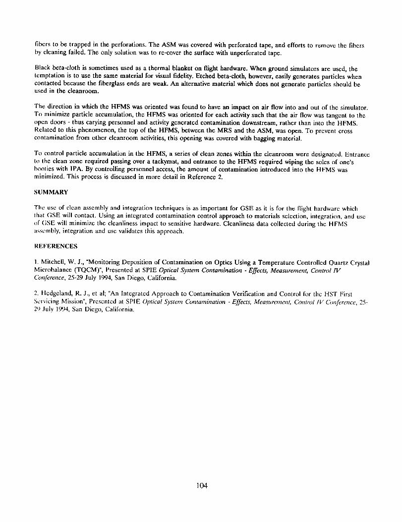
The verification requirements for HFMS parts during assembly and integration are shown in Table 1. Temporarymating surfaces, such as surfaces mated for match drilling, could be cleaned after the part was removed. Reflecting the
cleanable nature of these surfaces, verification to VCHS was considered acceptable. Similarly, non-mating surfaces that
were accessible for cleaning were verified to VCHS. Using a VCHS requirement instead of a 400B requirementallowed operations to continue without waiting for tapelift data. Surfaces which would become inaccessible for
verification due to the HFMS geometry were a concern because of airborne contaminant transport. Both direct and
indirect contamination transfer mechanisms were a concern because these surfaces could be contacted by personnel orhardware. Accordingly, these surfaces were verified to Level 400B. Because mated surfaces are not a source for direct
contact, indirect contact, or particle transport under ambient conditions, particulate cleanliness was not required to be
verified prior to mating. The possibility of volatile condensible contaminants from mated surfaces cross contaminatingother surfaces under ambient conditions was considered negligible due to the lack of a transport mechanism. To
minimize future outgassing due to surface Non Volatile Residue (NVR), each mating surface was wiped with IPA priorto mating. Mating surfaces which could be de-mated during crew familiarization in the HFMS had to meet the same
requirements as surfaces which were inaccessible. The modifications to the verification requiremcnts which wcrc
necessary to accommodate the different surface finishes and geometries are discussed further in the VerificationMethods section.
A similar analysis was performed for the HFMS GSE. Small tools were cleaned to the level of the hardware with
which they interfaced. Larger GSE, such as the Optical Telescope Assembly (OTA) dolly, were cleaned according to
101
thecrosscontamination risk that was posed. Surfaces in contact with the HFMS were verified to 400B or VCHS,
depending on the requirement of the surface with which they interfaced. Surfaces not in direct contact with the HFMS
were cleaned to VCHS (the same requirement as the HFMS exterior), except for those surfaces which were notaccessible to personnel. Because of the difficulty in reaching and verifying inaccessible surfaces, those surfaces were
cleaned for entry into the cleanroom or covered with bagging material and verified to Visibly Clean on a periodic basis.
These requirements are summarized in Table 2.
Verification Methods
The principle surface verification methods were the tapelift and solvent rinse. Unfortunately, not all surfaces were
amenable to these methods. Alternative verification methods were developed for painted surfaces, surfaces with
geometries that prohibited rinsing, and parts with less than the appropriate sampling area.
The solvent rinse technique often is not compatible with painted surfaces because the solvent will extract paint
components from the surface or react with the paint. In some cases, this can be solved by the choice of solvent;
however, for the HFMS only IPA was used to perform rinses. Rather than attempt to verify that no contamination was
present, the approach taken was to monitor incremental changes. This allowed the use of solvent swabs, which do not
contain enough solvent to endanger the paint integrity. The species detected were compared with previous swabsamples to ensure that no new source of contamination had impacted the surface. This approach was dependent upon
confidence in the initial cleanliness level. Maintenance of the painted surfaces in controlled environments following
painting provided this confidence.
Some surfaces and assemblies could not be rinsed because the geometry of the part prohibited collection of a solvent
rinse. These parts were swab sampled to determine qualitatively if any contaminant species were present. Once the
cleanliness of the part was established, routine cleaning was used to maintain the surfaces. Monitoring of nearby partsconfirmed the absence of volatile condensible contamination. Personnel training with respect to cross contamination
mechanisms assisted in maintaining the cleanliness of the surfaces.
Small parts, such as fasteners, shims, and standoffs, presented less surface than the standard sampling area. To rinse
these items, similar parts were grouped together after cleaning and rinsed as a batch. Once the parts were integrated
with a larger structure, the structure became the controlling surface for rinse sampling.
To improve confidence in the cleanliness of the surfaces which were not amenable to standard rinse techniques, the
entire HFMS was regularly inspected using an ultraviolet (UV) light. Many hydrocarbons fluoresce when illuminated
with UV light. To ensure that the critical Hub area, to which the Sis would be exposed, was free from condensible
hydrocarbons, a real-time NVR deposition monitor was installed: a Temperature Controlled Quartz CrystalMicrobalance (TQCM) with a magnesium fluoride (MgF_) coating operating three degrees centigrade below room
temperature was used to record NVR deposition. To eliminate possible unkonwn surface effects, the MgF 2coating was
used to mimic the coating on the SI optics. Although MgF 2coated TQCMs are sensitive to humidity (surface water
mass is indistinguishable from hydrocarbons), the assumption that all accumulation is caused by hydrocarbons was
conservative. Analysis of the TQCM response indicates a 1 Hz increase for a 2% relative humidity increase. Relative
humidity was usually 45% at 68 °F. The use of the TQCM in ambient conditions is discussed in detail in reference 1.
/Vlaterials Selection
Materials used inside the HFMS had to be cleanable to 400B, low outgassing, static dissipative, and abrasion resistant.
Verification of these criteria required an extensive test program. The test procedures were customized for each
material based upon the use and location of the material. The HST structure is a graphite-epoxy composite covered
with aluminum tape on the outside and multi-layer insulation (MLI) on the inside. The test process is depicted in
Figure 7. After screening the material for low outgassing properties (less than 1% TML and 0.1% CVCM per ASTM
E595) and the ability to meet Level 400 by tapelift before and after cleaning, the material entered a concurrent test
period. Static dissipation, NVR rinse, and dry abrasion testing were performed concurrently. Static dissipation was
checked for single layer and overlapped layers of tape. Abrasion testing was performed using a dry wipe; both the wipe
and the sample were microscopically examined. Finally, a vacuum outgassing test was performed in the Molecular
Kinetics (Molekit) facility.
102
Two materials, the aluminum tape used on the exterior of the HFMS and the beta cloth blankets intended for the
interior of the HFMS, illustrate the necessity for a comprehensive test program. The HST flight aluminum tape was
tested for use on the exterior and certain parts of the interior of the HFMS. In general, bare aluminum is a particlegenerating material because the oxide is easily abraded from the surface. Although most failed to meet the criteria for
internal use, certain tape samples met Level 400 when tapelifted; this may be due to mechanical hardening during the
tape fabrication process. Because the samples which passed were from the same roll as samples which failed, the tape
was rejected for use inside the ASM. The samples were inspected to VCHS and approved for use on the exterior ofthe HFMS.
Many of the HFMS internal surfaces are covered by blankets. To simulate the HST, black betacloth blankets were
baselined for use. The betacloth is a teflon coated fiberglass which is etched to produce the black color. This etchingprocess weakens the betacloth such that the material was easily abradable by personnel contact. A test plan similar to
the tape test plan was followed for several candidate blanket materials. In the case of the tape testing, the only cleaning
that was tested was solvent wiping with IPA. For the blanket samples, different cleaning methods were tested, includingnon-contact vacuuming and solvent rinsing. The material which was chosen was manufactured without the use of
silicone oil lubricant and was the only one which was non-porous. The non-porous aspect improved rinsability,cleanability, and abrasion resistance, and permitted verification to Level 400B.
DISCUSSION
Cleanliness Data
During assembly and integration of the HFMS, cleanliness samples were required whenever contamination generating
activities were completed. While the HFMS interior assembly was separate from the ASM, access for cleaning was not
precluded. Following integration with the ASM in April 1993, access for cleaning was restricted. From that pointforward, maintaining cleanliness was paramount. Cleanliness levels found during routine sampling of the HFMS
showed that the interior of the HFMS was better than Class 200. During heavy activity, cleanliness levels increasedslightly, but stayed below Level 400. Rinses taken from the FPD during integration and closeout were in the tenths of
milligrams per square foot. Selected routine sampling data is shown in Table 3; the July data was taken duringoperation of the HFMS.
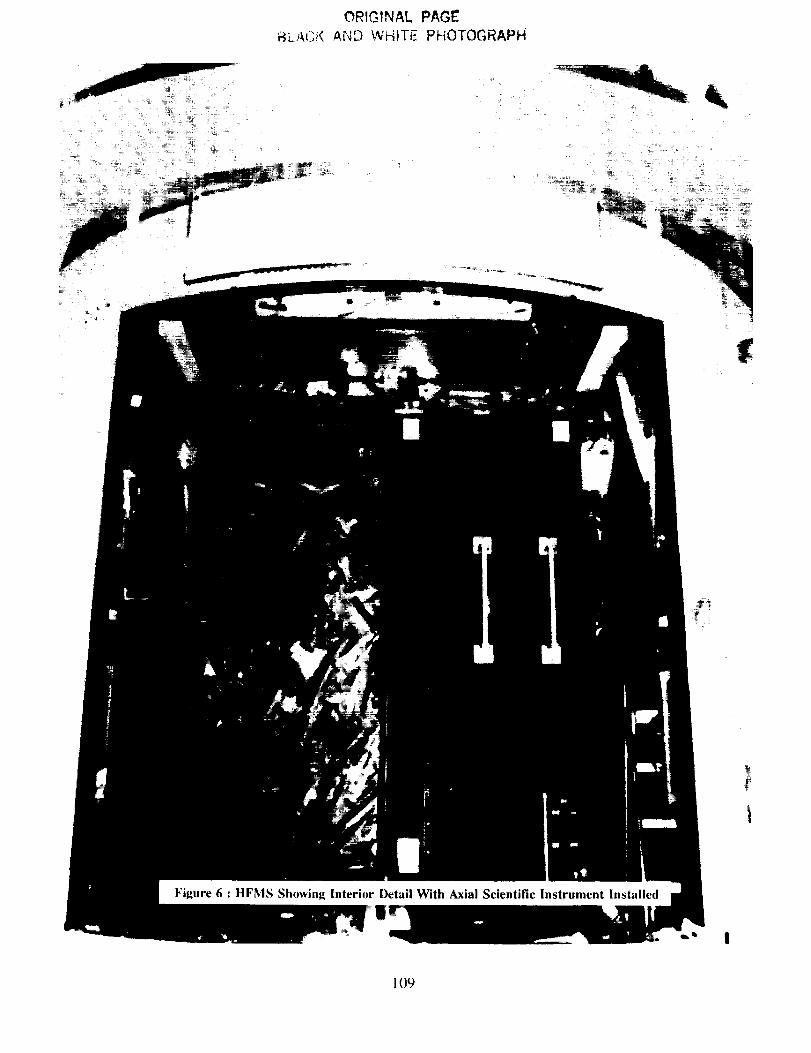
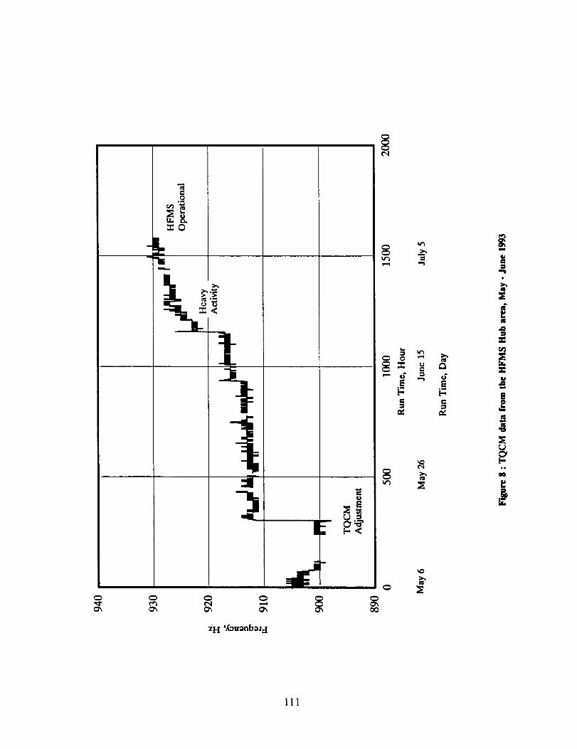
In May 1993, after the HFMS was integrated, a TQCM was installed in the hub area to monitor contamination
generated by cable routing and blanketing operations. The data from May through the end of June is shown in Figure
8. Two interesting items are evident on the graph: a 12 Hz jump in mid-May and a sudden increase in the
contamination rate in June. An investigation of the 12 Hz jump indicated that the jump was not caused bycontamination but was intrinsic to the TQCM._ The sudden increase around June 21 was caused by final closeout
activities. Though not shown, the rate of contamination remained low once the HFMS was operational; the TQCM
frequency at the end of SI testing was 935 Hz, compared with 930 Hz at the beginning. From the time of integration
until commissioning, the total NVR accumulation in the Hub area was 4.3x10 "2mg/ft 2 (30 Hz at 1.56x10 * g/cm 2/Hz).Optical witness mirrors placed near the TQCM showed no degradation at 121.6 nm during this period. Because swab
samples of the Hub taken before integration showed no materials other than the swab background, confidcnce washigh that the Level B requirement was maintained in the Hub area.
lessons Learned
Several significant contamination lessons were learned during the HFMS program. Some of these are related to surface
treatment, and others are relevant to cleanroom management.
It was found during assembly of the MRS that brush irridited aluminum does not possess the same resistance toparticle generation as dip irridited aluminum. Tapelifts from the brush irridited surface ranged from Level 500 to Level
750, whereas dip irridited surfaces were better than Level 300. Bare aluminum surfaces produced particles toonumerous to count.
Tape coverings for surfaces which will be used in vacuum are often perforated to prevent air bubbles. The direction of
perforation of paper backed tape is important; perforating from the backing side through to the tape surface causcs
Black beta-cloth is sometimes used as a thermal blanket on flight hardware. When ground simulators are used, the
temptation is to use the same material for visual fidelity. Etched beta-cloth, however, easily generates particles whencontacted because the fiberglass ends are weak. An alternative material which does not generate particles should beused in the cleanroom.
The direction in which the HFMS was oriented was found to have an impact on air flow into and out of the simulator.
To minimize particle accumulation, the HFMS was oriented for each activity such that the air flow was tangent to the
open doors - thus carying personnel and activity generated contamination downstream, rather than into the HFMS.
Related to this phenomenon, the top of the HFMS, between the MRS and the ASM, was open. To prevent cross
contamination from other cleanroom activities, this opening was covered with bagging material.
To control particle accumulation in the HFMS, a series of clean zones within the cleanroom were designated. Entranceto the clean zone required passing over a tackymat, and entrance to the HFMS required wiping the soles of one'sbooties with IPA. By controlling personnel access, the amount of contamination introduced into the HFMS was
minimized. This process is discussed in more detail in Reference 2.
SUMMARY
The use of clean assembly and integration techniques is as important for GSE as it is for the flight hardware which
that GSE will contact. Using an integrated contamination control approach to materials selection, integration, and useof (;SE will minimize the cleanliness impact to sensitive hardware. Cleanliness data collected during the HFMSassembly, integration and use validates this approach.
REFERENCES
1. Mitchell, W. J., "Monitoring Deposition of Contamination on Optics Using a Temperature Controlled Quartz Crystal
Microbalance (TQCM)", Presented at SPIE Optical System Contamination -Effects, Measurement, Control IVConference, 25-29 July 1994, San Diego, California.
2. Hcdgcland, R. J., et al; "An Integrated Approach to Contamination Verification and Control for the HST First
Servicing Mission", Presented at SPIE Optical System Contamh_ation -Effects, Measttrement, Control IV Conference, 25-2') July 1994, San Diego, California.
104
Table 1. Verification Requirements, HFMS Surfaces
Surfaces Metal or Tape Painted (Note 1) Rinse Prohibited