N95- 23804 MATERIAL INSPECTION OF EURECA FIRST FINDINGS AND RECOMMENDATIONS Marc Van Eesbeek, Michael Froggatt and Georges Gourrnelon ESA/ESTEC Noordwijk The Netherlands C) .... •j / ABSTRACT This paper gives the first results of the Post flight materials investigation on the European Retrievable Carrier (EURECA) after a stay of 11 months in LEO. The paper will concentrate on the first trmdings after the visual inspection performed at KSC and Astrotech and give some general design recommendations for potential future Carrier flights. INTRODUCTION This materials investigation is part of the more general Post-flight technology Investigations Programme on EURECA initiated by the ESA Technical Directorate and fully supported by the ESA/EURECA project team. This programme also includes a comprehensive meteoroid and debris investigation, inquiries into anomalies and failures at carder and experiment level and some basic technology studies (Ref 1). The material investigation is a joint effort between ESA/ESTEC Materials Division and DASA/ERNO materials specialists and consists of the following main activities • - Visual inspection shortly after landing at KSC (in OPF and VPF facilities) and during the disassembly of the carrier at Astrotech. More detailed inspections are in the process of being performed at ESTEC and at different Experimenters sites. - Photographic documentation of carrier and payload during these inspections. At this moment we have in total some 1200 photographs catalogued, 400 taken at KSC, the rest at Astrotech. 71 https://ntrs.nasa.gov/search.jsp?R=19950017384 2020-04-23T04:58:29+00:00Z
Transcript
N95- 23804
MATERIAL INSPECTION OF EURECA
FIRST FINDINGS AND RECOMMENDATIONS
Marc Van Eesbeek, Michael Froggatt and Georges GourrnelonESA/ESTEC
NoordwijkThe Netherlands
C) .... • j
/
ABSTRACT
This paper gives the first results of the Post flight materials investigation on the European RetrievableCarrier (EURECA) after a stay of 11 months in LEO.
The paper will concentrate on the first trmdings after the visual inspection performed at KSC and
Astrotech and give some general design recommendations for potential future Carrier flights.
INTRODUCTION
This materials investigation is part of the more general Post-flight technology Investigations
Programme on EURECA initiated by the ESA Technical Directorate and fully supported by theESA/EURECA project team.
This programme also includes a comprehensive meteoroid and debris investigation, inquiries
into anomalies and failures at carder and experiment level and some basic technology studies (Ref 1).
The material investigation is a joint effort between ESA/ESTEC Materials Division and
DASA/ERNO materials specialists and consists of the following main activities •
- Visual inspection shortly after landing at KSC (in OPF and VPF facilities) and
during the disassembly of the carrier at Astrotech. More detailed inspections are
in the process of being performed at ESTEC and at different Experimenters sites.
- Photographic documentation of carrier and payload during these inspections.
At this moment we have in total some 1200 photographs catalogued, 400 taken atKSC, the rest at Astrotech.
- Organic Contamination is measured using wipes and direct measurements. The
analyses first concentrate on IR-spectroscopy and will be followed by moresensitive ESCA and AUGER methods.
- Degradation of material properties due to exposure to the LEO-environment
(AO-effects, transmission losses in optics...)
- A database on the above has been developed by DASA/ERNO and contains already
results of visual inspection, photographic documentation, a/E measurements.
FIRST INSPECTION RESULTS
An overall EURECA configuration, experiment description and mission profile are given inRef.2. A schematic view of the integrated spacecraft can be seen in Fig 1. The solar arrays, located
on the +X and -X faces, are deployed to expose the radiator panels.
The majority of the experiments, except for the Inter Orbit Communication Antenna (IOC),are located on the top deck (+Z) either exposed or below the MLI tent. The multi-layer insulation
consists of a Beta Cloth top layer and a number of layers of double sided Acrylic coated Aluminised
Kapton (typically 20 layers). In order to avoid the contamination and degradation of the Beta Cloth,
found during solar simulation testing, it was decided to use a silicone-free version of this material.
Only some limited parts of the MLI were still consisting of the original silicone-containing material.
It should be mentioned that even the first thermo-optical measurements were taken only 4
weeks after retrieval and landing of the spacecraft. Some materials are liable to show a significant
recovery effect. After UV and particle irradiation tests performed at CERT/DERTS in Toulouse a
typical recovery of 0.1 within a few weeks after exposure to air has been found on PSG 120 FD paint.(Ref. 3.)
+Z face (sun-lit top face)
The Beta Cloth over the whole upper area is light brown in colour as a result of possible
contamination and UV irradiation, the total solar exposure being + 5000 e.s.h. This has led to an
increase of the Solar Absorptance of 0.07 on most of the blankets and up to 0.26 in very contaminated
areas. No appreciable change was found in the Normal Emittance values (see table 1).
72
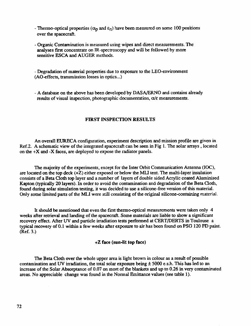
Therearesignsof outgassingfrom within thespacecraft(seephotos1to 5).Thesesignssometimescalled "nicotinestains"or brownstainsemanatefrom different unintentional venting
holes, e.g. around Attitude and Orbit Control System (AOCS sensors), the Atomic Oxygen Sample
Tray (AOST) experiment, Protein Crystallisation Facility (PCF) dome, the Advanced Solar Gallium
Arsenide Array (ASGA), GRAPPLE fixture etc.
The FEP tape (Sheldahl G401905 5 mil Silvered Perforated Teflon type A ) on the AOCS
sensors tower is heavily contaminated and typical shadowing effects can be seen.
On the Solar Constant and Variability Instrument (SOVA) the aluminised FEP-surface shows
non-homogeneous brown stains with a particular pattem, apparently due to temperature gradients on
the surface (see photo 6). It is believed that close to tape perforations and tape joints the temperature
is higher as a result of the much higher a/e-ratio and that therefore less condensation and subsequent
degradation occurs.
On several optical instruments a degradation of the performances was reported during the
flight. Contamination of the front optics was visible and will have contributed to these losses;
however, it also appeared that several of the front ffflters showed failures at interfaces between the
different layers. The pure contamination related degradation was highly wavelength dependent (see
Fig. 2.).
The amber reflector / orientation patch is blackened as a result of UV irradiation.
The MAP SG11FD white paint on the Solar Spectrum Instrument (SOSP) is slightly tan
coloured as a consequence of UV irradiation, resulting in an increase in o_of 0.2 and an increase in eof 0.015.
-Z face (bottom)
There are again signs of outgassing from within the spacecraft. This is very obvious on
blankets, around battery boxes and around struts. An increase in a of up to 0.026 was recorded in thecontaminated areas. The direct solar irradiation was low since the -Z face was earth oriented during
the whole mission, except for a very limited time span, estimated at max 30 hrs, during manoeuvering
in the fast days of the mission. This could mean that the effect of Albedo UV-radiation in the
degradation process cannot be neglected.
The baseplate of the Power Control Unit (PCU), painted in PSG 120 FD, which was recessed
approx. 10 cm from the front face of the PCU was degraded (contamination + Albedo UV). The
maximum resulting increase in a was 0.13. It is believed that this increase was mainly due to a
polymerisation of a contaminant rather than a degradation of the paint itself.
Onthe IOC antenna dish some marks from previous bonding of thermocouples were visible.
Marks caused by possible cleaning prior to flight were accentuated by some environmentalinteractions (UV, Atomic Oxygen ?). Some iridescence on the black thermal blanket was visible as aresult of contamination.
+X and -X faces
In general the Beta Cloth is less degraded than on the +Z face (top face), as can be expected
from the smaller solar input. This has resulted in an increase of the Solar Absorptance of 0.02 on most
of the blankets and up to 0.055 in more contaminated areas (close to ventings).
The EURECA signs (both on -X and +X) show some slight browning of the white paint
(PSG120FD), resulting in a Ao_ of +0.07.
The green orientation patch has darkened.
Very prominent degradation of outgassing products is visible on PCF dome where the blanket
meets the PSG120FD white paint (see photo 7). Some concentration effect of this degradation is dueto multi-reflections in small V-grooves formed between both blanket and dome. The degradation on
the top side (+Z) of the dome resulted in an increase in tx varying between 0.13 and 0.20, while on theside this increase was limited to 0.04.
The PSG120FD white painted Aluminised Kapton foil from the MLI below the hydrazine
thrusters is cracked and peeling due to mechanical and thermal stresses. Also disbonding of folded-
over edges on these foils occurred.
The darkening of the MLI in the area of the PCF can be seen in photo 8 where the contrast is
obvious between the shaded area below the strut of the payload tent and the exposed area.
+Y face
Here also there are signs of outgassing from within the spacecraft. They are particularly
obvious below the Timeband Capture Cell Experiment ('I'ICCE) and behind the Radiofrequency Ion
Thruster Assembly (RITA) where there was an unintentional opening in the MLI cover that acted as a
chimney (see photo 9). This has resulted in an increase of the Solar Absorptance of 0.06 on most of
74
theblanketsandup to 0.13in very contaminatedareas.No appreciable change was found in the
Normal Emittance values (see table 1).
The Aluminised FEP (Sheldahl G400900 perforated) on RITA has degraded, due to UV
irradiation and Atomic Oxygen attack. Some crazing near perforation holes was visible on the sun-
exposed side.The degradation and splitting of the shrink sleeve surrounding the RF power supply cable of the
thruster is mainly resulting from an improper thermal blanket design.
The SCUFF PLATE shows signs of ATOX degradation of the yellow Chemglaze Z853 and
the black Z306 paint. The paint is powdering and faded. The paint shows a bad adhesion and is
peeling from the substrate (see photo 10).
-Y face
There are signs of outgassing from within the spacecraft. They are particularly obvious behind
the Wide Angle Telescope For Cosmic Hard X-rays (WATCH) and on the Freon line MLI, as shown
in photo 11.
This has resulted in an increase of the Solar Absorptance of 0.06 on most of the blankets and
up to 0.13 in very contaminated areas, similar to the +Y face. No appreciable change was found in theNormal Emittance values.
The GRAPPLE fixture shows signs of UV/ATOX degradation of the grey paint, a blend of
Chemglaze black paint "VI'-C-542 type 2 and a Chemglaze white paint TI'-C-542 type 1 (Ref. 4), with
a shadowing effect, possibly from the grab arm. The paint is powdering and faded. NASA is
investigating if outgassing from the RMS arm has discoloured the GRAPPLE plate.
Inside
The general appearance of the interior of the spacecraft was visibly clean and no apparent
problems were noted on painted areas, harness or structure.
The Aluminium tape used to bond cables on the black painted top platform (behind TICCE)has disbonded in some areas.
75
CONCLUSIONS
Although there is an overall contamination and a noticeable degradation on the +Z face as a
result of UV-irradiation, most visual degradation effects axe due to venting through apertures from
inside the spacecraft, such as e.g. overlaps between thermal blankets. This contamination has
polymerised and has darkened under the action of solar Ultraviolet at these vent holes, resulting in the"nicotine stains", very well known from the LDEF after-flight visual inspections.
Also the Earth-facing surfaces showed some brown degradation. These surfaces were sun-lit
only during some short manoeuvering periods (total estimated sun exposure < 20hrs). Although the
UV in the albedo spectrum is very limited, one cannot exclude this effect totally.
The usefulness of shutters for optical experiments is well demonstrated by the SOSP
experiment, where the contamination was conf'med to the upper side of the shutters rather than on the
underlaying optical elements.
RECOMMENDATIONS FOR FUTURE EURECA-FLIGHTS
Since the primary mission objective was microgravity oriented, most of the experiments werebuilt contamination insensitive. There were however some optics on-board that degraded heavily due
to deposition and degradation effects. There are some simple measures that can be taken that will
reduce the contamination potential for these critical surfaces, namely:
- As far as possible all optical apertures should be within a single plane.
- Use shutters for optical payloads when appropriate.
- No venting shall be allowed in the vicinity or in view of optical apertures, optics and coldsurfaces.
- Venting should be directed as much as possible to the wake region.
- Control the thermal blanket design and manufacture to avoid undesired venting due to gaps
between different elements. Overlaps, if used, should not be vent openings. It is preferable to
have the edges butting to each other and tightly joined.
- A bake should be applied to the carder, the harness, and the different experiments in order
to assure a cleanliness level in conformance with the needs dictated by the most sensitiveexperiments or sub-systems and to avoid all cross contamination.
- Cleanliness and contamination control specifications ( e.g. during manufacturing, testing,
handling, packaging, storage) to the appropriate level shall be implemented not only on
76
optical payloads, but on the whole spacecraft, including the non-sensitive payloads. This also
includes a close follow-up by means of Critical Cleanliness Reviews at payload and
spacecraft interface levels.
AKNOWLEDGEMENTS
We wish to thank the EURECA project teams and experimenters for the valuable support received
during the inspection activities at the different sites.
We also wish to thank the DASA/ERNO materials team, U. Rieck, H. Kersting, B. Schwarz, H.J.
Rosik for the cooperative effort in documenting, inspection and photographic data.
We would also like to thank J. Guijt and T. Harper for the various analyses and interesting
discussions towards the contamination work performed.
REFERENCES
ReL 1 ;R. #,ceil, G. Drolshagen, L Gerlach, G. Racca. Meteoroid and Debris Investigation on Eureca;
ESA/ESTEC. First European Conference on Space Debris. ESA SD-01
Ref. 2. A. Dover, R. Aceti and G. Drolshagen ESA/ESTEC EURECA 11 Months in Orbit - Initial
PHOTOGRAPH N ° 1. View of AOCS sensor tower showing brown stain in top left-hand corner
caused by venting of outgassed materials from within the spacecraft.(NASA photo)
Venting pathbetween MLI
PHOTOGRAPH N ° 2. View of venting path between MLI blankets. (NASA photo)
81
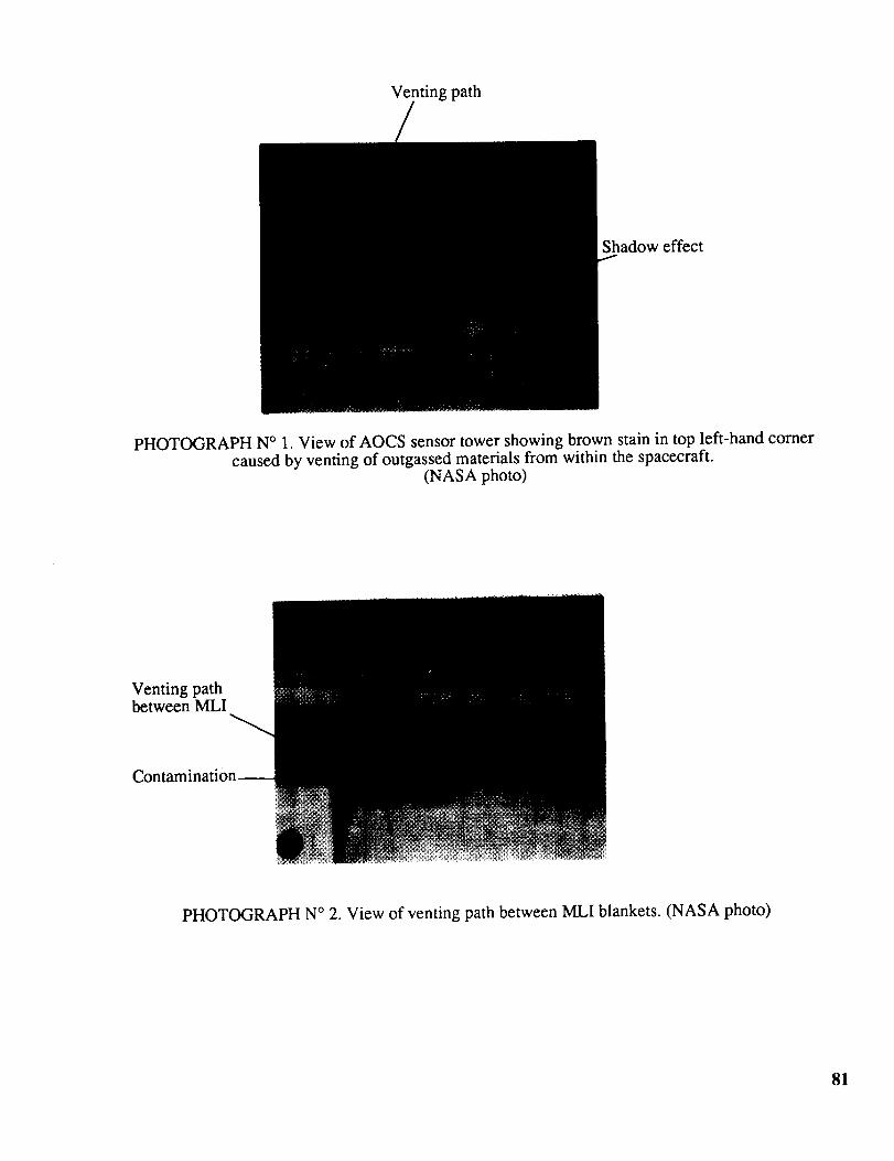
+Z
Ventingpal
Polymerisedcontamination
PHOTOGRAPHN° 3. View of brownstaincausedby outgassedmaterialbeingpolymerisedby UV irradiationaftercondensingonBetacloth. (NASA photo)
GapbetweenMLI
Polymerisedcontamination
PHOTOGRAPHN° 4. View of brownstainemanatingfrom within thespacecraft.This is typicalof themanystainsobservedaroundthespacecraftcausedby outgassedmaterialventingfrom
betweentheMLI. (NASA photo)
82
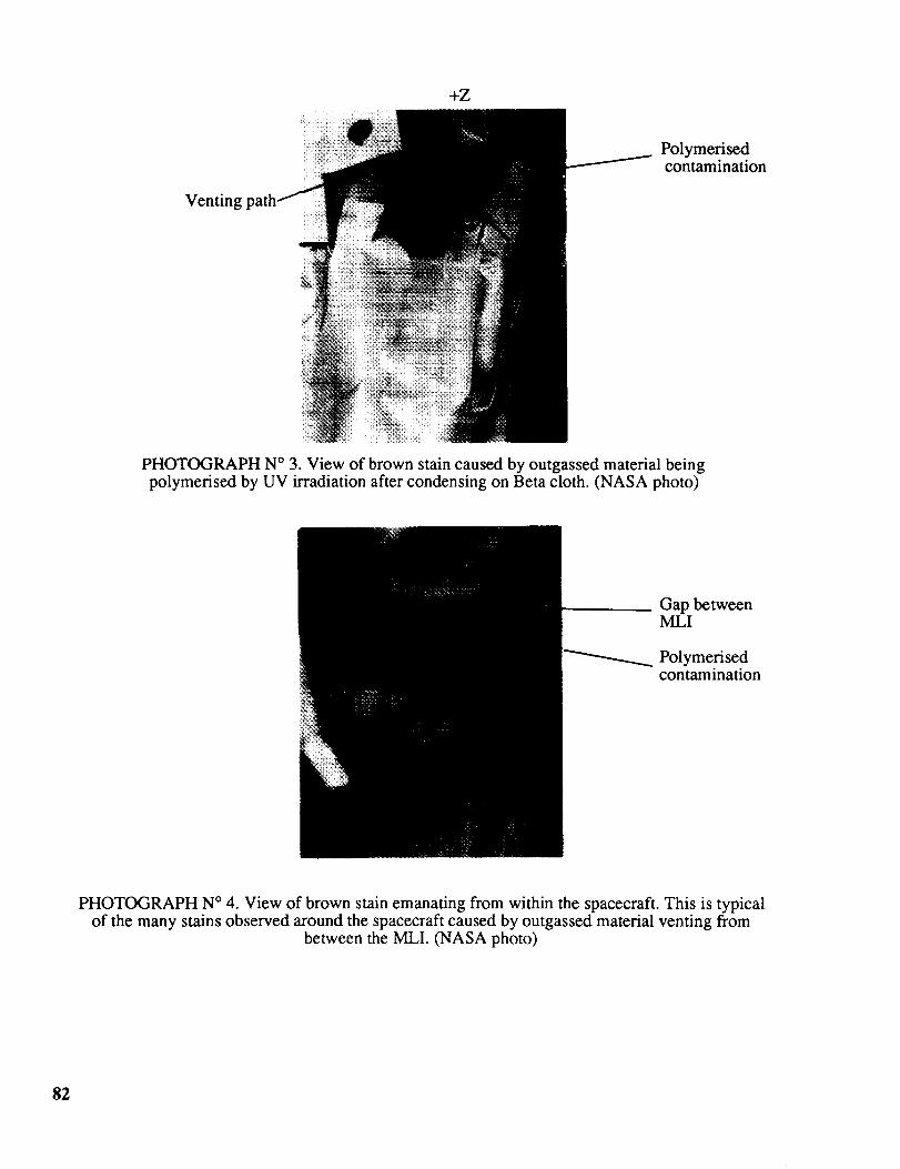
geofgrapplefixture
PHOTOGRAPHN ° 5. View of UV degradation and outgassed material deposited and
polymerised on the MLI surrounding the grapple fixture. Notice the image caused by the shadowof the grapple on the MLI. (DASA ERNO photo)
Non-homogeneousstains
cover
PHOTOGRAPH N ° 6. View of SOVA experiment. Notice the non-homogeneous stains on the
aluminised FEP tape due to temperature gradients on the surface at perforations and tape joints.(NASA photo)
83
Darkerareas
PHOTOGRAPHN° 7. View of UV degradationandoutgassedmaterialdepositedandpolymerised on the interface between the white PSG120FD paint on the PCF dome and the
surrounding MLI. Notice darker areas caused by multi reflections in small V-groovesbetween blanket and dome. (DASA ERNO photo)
Tent strut
of
tent strut
PHOTOGRAPH N ° 8. View of PCF dome and the surrounding MLI. Notice the shaded area
below the payload tent strut where the Beta cloth is not degraded by UV irradiation orpolymerised contaminants. (NASA photo)
84
Gap behind RITA-plate
PHOTOGRAPH N ° 9. View of RITA. Notice gap behind back plate which provides a
chimney for outgassed materials to vent from within the spacecraft. (NASA photo)
PHOTOGRAPH N ° 10. View of Chemglaze Z853 yellow paint peeling from -Y scuff plate.(NASA photo)