N95- 28466 Composite Fuselage Shell Structures Research at NASA Langley Research Center James H. Starnes, Jr. and Mark J. Shuart NASA Langley Research Center Hampton, VA 23665-5225 ///; Introduction Fuselage structures for transport aircraft represent a significant percentage of both the weight and the cost of these aircraft primary structures. Composite materials offer the potential for reducing both the weight and the cost of transport fuselage structures, but only limited studies of the response and failure of composite fuselage structures have been conducted for transport aircraft. Before composite materials can be applied safely and reliably to transport fuselage structures, the behavior of these important primary structures must be understood and the structural mechanics methodology for analyzing and designing these complex stiffened shell structures must be validated in the laboratory. Methods for accurately predicting the nonlinear response and failure of structurally efficient, cost-effective stiffened composite shell structures must be developed and validated. The effects of local gradients and discontinuities on fuselage shell behavior and the effects of local damage on pressure containment must be thoroughly understood before composite fuselage structures can be used for commercial transport aircraft. The present paper describes the research being conducted and planned at NASA Langley Research Center to help understand the critical behavior of composite fuselage structures and to validate the structural mechanics methodology being developed for stiffened composite fuselage shell structure subjected to combined internal pressure and mechanical loads. Stiffened shell and curved stiffened panel designs are currently being developed and analyzed, and these designs will be fabricated and then tested at Langley to study critical fuselage shell behavior and to validate structural analysis and design methodology. The research includes studies of the effects of combined internal pressure and mechanical loads on nonlinear stiffened panel and shell behavior, the effects of cutouts and other gradient-producing discontinuities on composite shell response, and the effects of local damage on pressure containment and residual strength. Scaling laws are being developed that relate full-scale and subscale behavior of composite fuselage shells. Failure mechanisms are being identified and advanced designs will be developed based on what is learned from early results from the Langley research activities. Results from combined load tests will be used to validate analytical models of critical nonlinear response mechanisms as well as shell scaling laws. /z]W, CEDING.PA_,%_• ,_. _,,,..... , . 631 https://ntrs.nasa.gov/search.jsp?R=19950022045 2018-07-09T02:17:00+00:00Z
Transcript
N95- 28466
Composite Fuselage Shell Structures Research atNASA Langley Research Center
James H. Starnes, Jr. and Mark J. ShuartNASA Langley Research Center
Hampton, VA 23665-5225
///;
Introduction
Fuselage structures for transport aircraft represent a significant percentage of both theweight and the cost of these aircraft primary structures. Composite materials offer thepotential for reducing both the weight and the cost of transport fuselage structures, butonly limited studies of the response and failure of composite fuselage structures havebeen conducted for transport aircraft. Before composite materials can be appliedsafely and reliably to transport fuselage structures, the behavior of these importantprimary structures must be understood and the structural mechanics methodology foranalyzing and designing these complex stiffened shell structures must be validated inthe laboratory. Methods for accurately predicting the nonlinear response and failure ofstructurally efficient, cost-effective stiffened composite shell structures must bedeveloped and validated. The effects of local gradients and discontinuities onfuselage shell behavior and the effects of local damage on pressure containment mustbe thoroughly understood before composite fuselage structures can be used forcommercial transport aircraft.
The present paper describes the research being conducted and planned at NASALangley Research Center to help understand the critical behavior of compositefuselage structures and to validate the structural mechanics methodology beingdeveloped for stiffened composite fuselage shell structure subjected to combinedinternal pressure and mechanical loads. Stiffened shell and curved stiffened paneldesigns are currently being developed and analyzed, and these designs will befabricated and then tested at Langley to study critical fuselage shell behavior and tovalidate structural analysis and design methodology. The research includes studies ofthe effects of combined internal pressure and mechanical loads on nonlinear stiffenedpanel and shell behavior, the effects of cutouts and other gradient-producingdiscontinuities on composite shell response, and the effects of local damage onpressure containment and residual strength. Scaling laws are being developed thatrelate full-scale and subscale behavior of composite fuselage shells. Failuremechanisms are being identified and advanced designs will be developed based onwhat is learned from early results from the Langley research activities. Results fromcombined load tests will be used to validate analytical models of critical nonlinearresponse mechanisms as well as shell scaling laws.
The objectives of the Langley composite fuselage shell structures research programare to develop the structural mechanics methodologies needed to predict reliably theresponse and failure of composite fuselage shell structures that are subjected tocombined internal pressure and mechanical loads, and to understand the effects oflocal damage on the damage tolerance and residual strength of these structures.These structural mechanics methodologies include structural analysis methods,structural sizing procedures and structural scaling methods. The structural analysismethods will be used to predict the nonlinear response of internally pressurizedfuselage shells and the local stress and deformation gradients that cause failure incomposite shells with discontinuities. The structural sizing procedures will be used toconduct minimum weight design studies for candidate shell design concepts and todetermine the sensitivity of the response and structural weight of a design to changesin structural parameters. The structural scaling methods will be used to study subscalemodels of candidate design concepts in an attempt to reduce the cost of designdevelopment by minimizing the amount of full-scale development testing needed for anew structural design The structural mechanics methodologies developed by thisresearch effort will be verified in the laboratory by conducting experiments with curvedstiffened composite panels and pathfinder pressurized composite shells. Theseexperiments will also identify critical failure modes and the effects of local damage andstress and deformation gradients on composite shell behavior.
Objectives: Develop verified structural mechanics methodologies forreliably predicting the response and failure of compositefuselage structure subjected to combined internal pressureand mechanical loads and to local damage
Approach:
Develop and apply structural analysis methods that predict thenonlinear response and failure of composite fuselage shellstructures with combined loads
Develop structural sizing procedures and conduct parametricstudies for structurally efficient composite fuselage shellstructures with combined loads
• Develop scaling methodology for composite fuselage shellswith combined loads
• Test benchmark curved panels and pathfinder stiffened shells toidentify critical failure modes, to verify structural analysis methods,and to understand the effects of local damage and gradients oncomposite shell behavior
Figure 1
632
PRESSURIZED COMPOSITE FUSELAGE SHELL
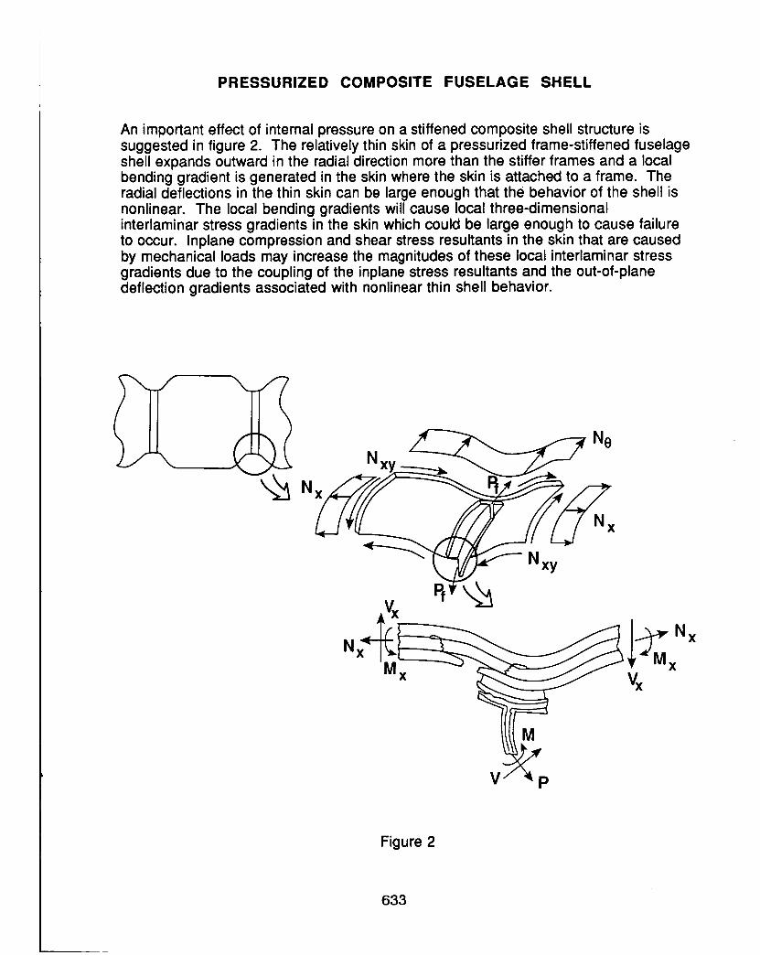
An important effect of internal pressure on a stiffened composite shell structure issuggested in figure 2. The relatively thin skin of a pressurized frame-stiffened fuselageshell expands outward in the radial direction more than the stiffer frames and a localbending gradient is generated in the skin where the skin is attached to a frame. Theradial deflections in the thin skin can be large enough that the behavior of the shell isnonlinear. The local bending gradients will cause local three-dimensionalinterlaminar stress gradients in the skin which could be large enough to cause failureto occur. Inplane compression and shear stress resultants in the skin that are causedby mechanical loads may increase the magnitudes of these local interlaminar stressgradients due to the coupling of the inplane stress resultants and the out-of-planedeflection gradients associated with nonlinear thin shell behavior.
N'____ Ne
Nxy
xy
P
Figure 2
633
COMPOSITE FUSELAGE SHELL STRUCTURES RESEARCHSHELL ANALYSIS AND SIZING STUDIES
Nonlinear shell analysis and structural sizing studies for the Langley compositefuselage shell structures research program are indicated in figure 3. The effects ofcombined internal pressure and mechanical loads on nonlinear structural responsewill be studied analytically. The postbuckling response of the skin and theredistribution of internal loads associated with stiffness changes due to nonlinear skin
buckling response and damage propagation will be included in the nonlinearanalyses. The local stress and deformation gradients associated with local details,discontinuities and eccentricities will be determined for accurate failure analyses andthe effects of shell curvature on nonlinear behavior and local gradients will also bestudied. Structural design studies will be conducted to determine minimum-weightdesigns for candidate design concepts subjected to combined internal pressure andmechanical loads. Studies will also be conducted to determine the sensitivity of theresponse and failure of candidate minimum-weight design concepts to changes instructural parameters.
Nonlinear Shell Analysis
Stiffened shell response to pressure and mechanical loadsPostbuckling responseLocal deformation and stress gradients caused by localdetails, discontinuities and eccentricitiesCurvature effectsLocal stress fields for failure predictionsInternal load redistribution associated with stiffness changesdue to nonlinear response and damage
Structural Sizing Studies
Minimum-weight design studies for pressure and mechanicalloadsParametric studies
Figure 3
634
COMPOSITE FUSELAGE SHELL STRUCTURES
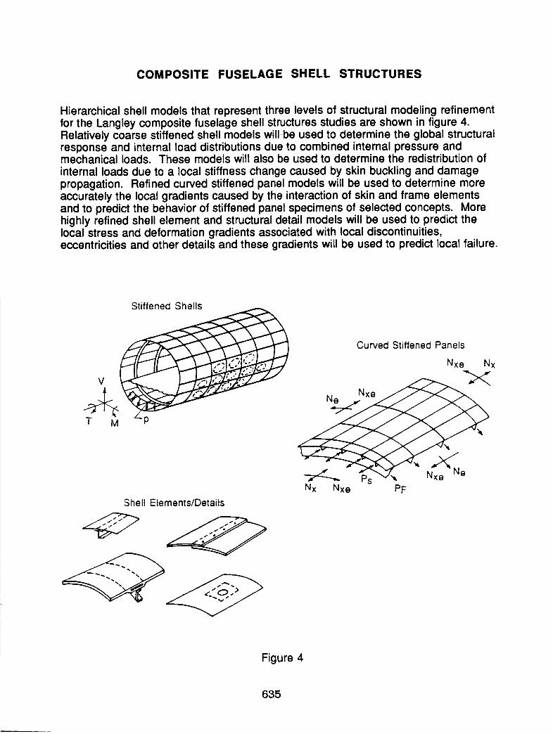
Hierarchical shell models that represent three levels of structural modeling refinementfor the Langley composite fuselage shell structures studies are shown in figure 4.Relatively coarse stiffened shell models willbe used to determine the global structuralresponse and internal load distributions due to combined internal pressure andmechanical loads. These models will also be used to determine the redistribution ofinternal loads due to a local stiffness change caused by skin buckling and damagepropagation. Refined curved stiffened panel models will be used to determine moreaccurately the local gradients caused by the interaction of skin and frame elementsand to predict the behavior of stiffened panel specimens of selected concepts. Morehighly refined shell element and structural detail models will be used to predict thelocal stress and deformation gradients associated with local discontinuities,eccentricities and other details and these gradients will be used to predict local failure.
Stiffened Shells
T M P
Shell Elements/Details
Curved Stiffened Panels
Nxe Nx
Nx Nxe PF
Figure 4
635
EFFECT OF INTERNAL PRESSURE ON COMPOSITESHELL STRUCTURES
An example of results for a stiffened shell analysis model currently being studied isshown in figure 5. The shell model is based on the current Boeing design beingdeveloped under NASA contract NAS1-18889 and is being used to develop theLangley pathfinder half-scale stiffened shell design. The shell radius is 122 inches,the shell length is 264 inches and the shell skin is made from a [+45/90/0/+60/90]sgraphite-epoxy laminate. The shell is loaded by an internal pressure of 10.35 psi. Themodel includes 3 skin bays with discrete stringers, frames and floor beams. The figureshows the effects of the stringers, frames and floor beams on the hoop stress resultantdistribution in the skin. These results indicate that the value of the hoop stressresultant is significantly affected by the interaction of the skin and the frames, stringersand floor beams.
EFFECT OF INTERNAL PRESSURE ON UNSTIFFENED CURVEDGRAPHITE-EPOXY PANEL RESPONSE
An example of the effects of internal pressure on the response of curved unstiffenedgraphite-epoxy panels is taken from ref. 1 and shown in figure 6. The panels are 20inches long, 8 inches wide and have a 60 inch radius. Analytical and experimentalout-of-plane deflections w at the center of the panel are shown in the lower left figureas pressure increases for 5-, 8- and 16-ply-thick panels. These results show that thepanels stiffen as the pressure is increased and that the pressure-deflection responsecurves are nonlinear. The circumferential or hoop strain distribution along the x orcircumferential coordinate from the center of the panel to a panel edge is shown in thelower right figure for an 8-ply-thick panel with 50 psi internal pressure. Inside andoutside surface strain results indicate that a significant bending strain gradient existsnear the panel edge. This bending strain gradient is severe enough to cause thepanel to fail along this edge as shown in the upper right photograph.
Curved panel geometry
8 in. X
Nonlinear effect of pressureon center deflection
200 I- -- Analysis
I'- ?_I_ oc_ Test
120 I'- ,_o_] L 16-ply
Pressure, L _l 8 Ipsi PY,orEi:,
0 0.25 0.50
W center, in.
_-- Failure location
Circumferential strain
-0.01
8-ply
0.02 f p-50 psi-- Analysis
[3 Test
0.01 ,__
_ Outside-/-_
] i I J01 2 34
X, in.
Figure 6
637
FIRST MAJOR FRACTURE EVENT AND ULTIMATE FAILURE LOAD
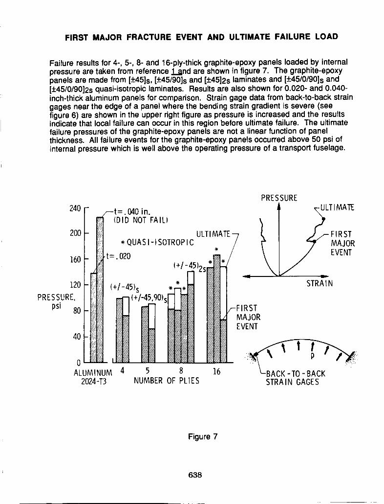
Failure results for 4-, 5-, 8- and 16-ply-thick graphite-epoxy panels loaded by internalpressure are taken from reference land are shown in figure 7. The graphite-epoxypanels are made from [_+45]s, [_45/90]s and [+4512s laminates and [+45/0/90]s and[+_.45/0/9012s quasi-isotropic laminates. Results are also shown for 0.020- and O.040-inch-thick aluminum panels for comparison. Strain gage data from back-to-back straingages near the edge of a panel where the bending strain gradient is severe (seefigure 6) are shown in the upper right figure as pressure is increased and the resultsindicate that local failure can occur in this region before ultimate failure. The ultimatefailure pressures of the graphite-epoxy panels are not a linear function of panelthickness. All failure events for the graphite-epoxy panels occurred above 50 psi ofinternal pressure which is well above the operating pressure of a transport fuselage.
PRESSURE
240 F- _t- 040 i n _,ULTI MATE
_I (DI'DNOT'FAIL) k _'
_oo-_ u_,_T_-_ ( f_-_,_s__I , QUAS I-I SOTROP IC / I" _ MAJOR
_'t "2" / \ _ EVENT16o- !_ =.uo -_ .1_./ \
o _ ,® NI _ ® ._:_' _' _;.ALUMINUM 4 5 8 16 " LBACK.TO_BACK ""
2024-T3 NUMBER OF PLIES STRAIN GAGES
Figure 7
638
EFFECT OF STIFFENER BENDING STIFFNESS ON PRESSURIZEDGRAPHITE-EPOXY PANEL RESPONSE
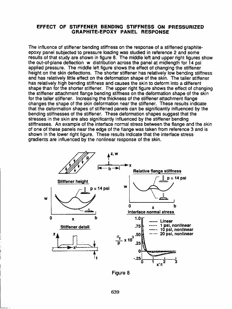
The influence of stiffener bending stiffness on the response of a stiffened graphite-epoxy panel subjected to pressure loading was studied in reference 2 and someresults of that study are shown in figure 8. The middle left and upper right figures showthe out-of-plane deflection w distribution across the panel at midlength for 14 psiapplied pressure. The middle left figure shows the effect of changing the stiffenerheight on the skin deflections. The shorter stiffener has relatively low bending stiffnessand has relatively little effect on the deformation shape of the skin. The taller stiffenerhas relatively high bending stiffness and causes the skin to deform into a differentshape than for the shorter stiffener. The upper right figure shows the effect of changingthe stiffener attachment flange bending stiffness on the deformation shape of the skinfor the taller stiffener. Increasing the thickness of the stiffener attachment flangechanges the shape of the skin deformation near the stiffener. These results indicatethat the deformation shapes of stiffened panels can be significantly influenced by thebending stiffnesses of the stiffener. These deformation shapes suggest that thestresses in the skin are also significantly influenced by the stiffener bendingstiffnesses. An example of the interface normal stress between the flange and the skinof one of these panels near the edge of the flange was taken from reference 3 and isshown in the lower right figure. These results indicate that the interface stressgradients are influenced by the nonlinear response of the skin.
_Z_ WIb_ l
Stiffener height
0 x b
W
Stiffener detail
Relative flange stiffness
14 psi
I
0 x b
Interface normal stress
1"0 f _ Linear
.75 1 psi, nonlinear10 psi, nonlinear
1-30.50 20 psi, nonlinearo, X
p ,25_0 .
-.25
0 1 x,/t 2 3
Figure 8
639
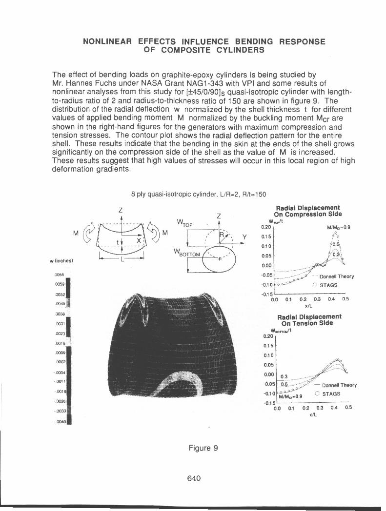
NONLINEAR EFFECTS INFLUENCE BENDING RESPONSE OF COMPOSITE CYLINDERS
0.20 - 0.1 5
0.1 0
0.05
0.00
-0.1 0
-0.15.
The effect of bending loads on graphite-epoxy cylinders is being studied by Mr. Hannes Fuchs under NASA Grant NAG1-343 with VPI and some results of nonlinear analyses from this study for [+45/0/90]~ quasi-isotropic cylinder with length- to-radius ratio of 2 and radius-to-thickness ratio of 150 are shown in figure 9. The distribution of the radial deflection w normalized by the shell thickness t for different values of applied bending moment M normalized by the buckling moment Mcr are shown in the right-hand figures for the generators with maximum compression and tension stresses. The contour plot shows the radial deflection pattern for the entire shell. These results indicate that the bending in the skin at the ends of the shell grows significantly on the compression side of the shell as the value of M is increased. These results suggest that high values of stresses will occur in this local region of high deformation gradients.
Mf&r=O.9 .i"c
. Y0.S.j
8 , : I
?0.6r, : r-\ :
,& --\t /.p ,.a0 - ",/ (> STAGS
. , -. - - ' CXmnelf Theory
'
8 ply quasi-isotropic cylinder, UR=2, R/t=l50
M
w (inches)
iJC66
Z
M
Figure 9
640
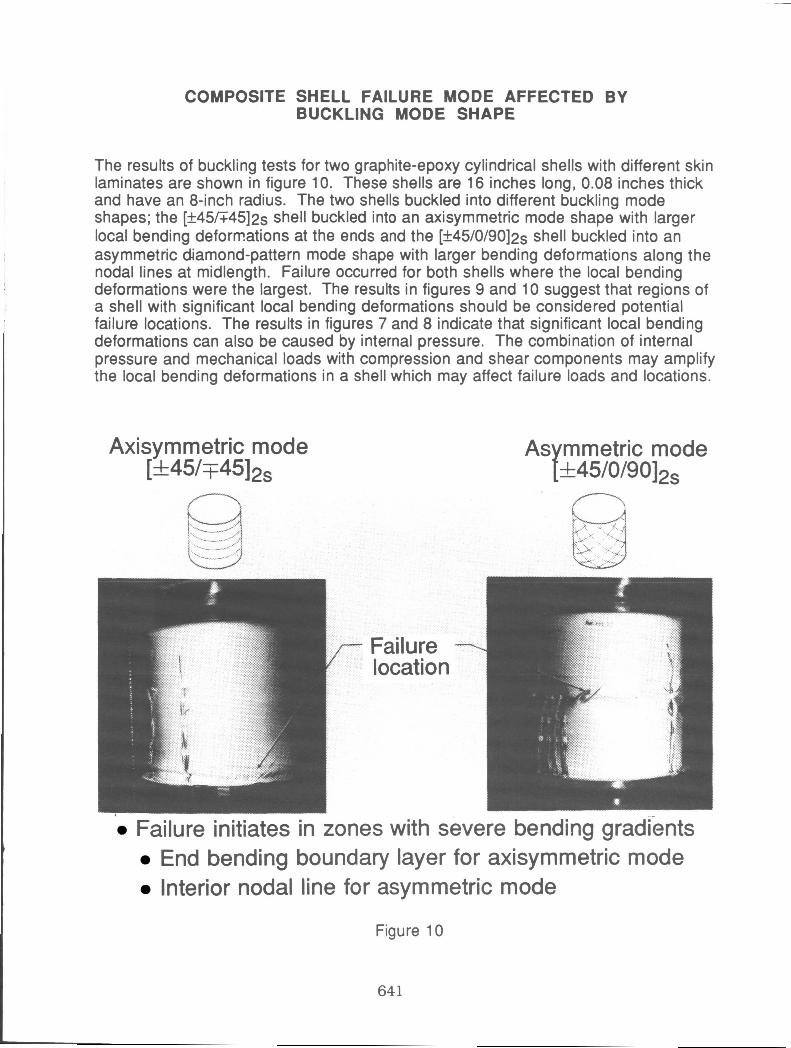
COMPOSITE SHELL FAILURE MODE AFFECTED BY BUCKLING MODE SHAPE
The results of buckling tests for two graphite-epoxy cylindrical shells with different skin laminates are shown in figure 10. These shells are 16 inches long, 0.08 inches thick and have an 8-inch radius. The two shells buckled into different buckling mode shapes; the [+45/T45]2~ shell buckled into an axisymmetric mode shape with larger local bending deformations at the ends and the [+45/0/90]2s shell buckled into an asymmetric diamond-pattern mode shape with larger bending deformations along the nodal lines at midlength. Failure occurred for both shells where the local bending deformations were the largest. The results in figures 9 and 10 suggest that regions of a shell with significant local bending deformations should be considered potential failure locations. The results in figures 7 and 8 indicate that significant local bending deformations can also be caused by internal pressure. The combination of internal pressure and mechanical loads with compression and shear components may amplify the local bending deformations in a shell which may affect failure loads and locations.
Axisymmetric mode [ &45/145]2,
As mmetric mode Y- +45/0/90]2,
Failure location
Failure initiates in zones with severe bending gradients End bending boundary layer for axisymmetric mode Interior nodal line for asymmetric mode
I
Figure 10
64 1
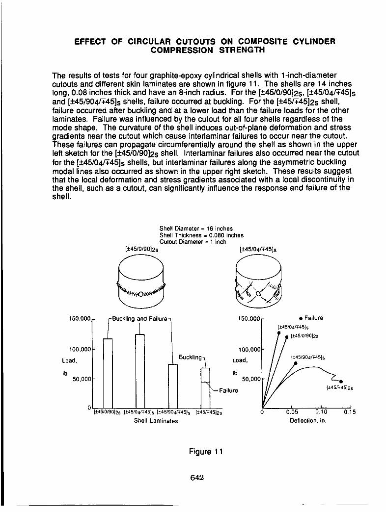
EFFECT OF CIRCULAR CUTOUTS ON COMPOSITE CYLINDERCOMPRESSION STRENGTH
The results of tests for four graphite-epoxy cylindrical shells with 1-inch-diametercutouts and different skin laminates are shown in figure 11. The shells are 14 incheslong, 0.08 inches thick and have an 8-inch radius. For the [+45/0/9012s, [__.45/04/_45]sand [+45/904_45]s shells, failure occurred at buckling. For the [+45_4512s shell,failure occurred after buckling and at a lower load than the failure loads for the otherlaminates. Failure was influenced by the cutout for all four shells regardless of themode shape. The curvature of the shell induces out-of-plane deformation and stressgradients near the cutout which cause interlaminar failures to occur near the cutout.These failures can propagate circumferentially around the shell as shown in the upperleft sketch for the [+45/0/9012s shell. Interlaminar failures also occurred near the cutoutfor the [+45/04/$45]s shells, but interlaminar failures along the asymmetric bucklingmodal lines also occurred as shown in the upper right sketch. These results suggestthat the local deformation and stress gradients associated with a local discontinuity inthe shell, such as a cutout, can significantly influence the response and failure of theshell.
150,000-
100,000 -
Load,
Ib50,000 -
Shell Diameter = 16 inches
Shell Thickness = 0.080 inchesCutout Diameter = 1 inch
[+45/0/9012s [+45/04/_45]s
-Buckling and
_L
o I[+45/0/9012s [+45/04_45]s [:t:45/904_45]s
Shell Laminates
Failure 150,000 r • Failure
i I {:t:45/O4/V45]s
/ /O 7) [±45/0/9012s
i 100,000r / /
Buckling_ _//__'___/
I IIIb 50,000
Failure I/// [+45,%45}2s
V I I I[:!:45_45]2s 0 0.05 O. 10 O.1 5
Deflection, in.
Figure 11
642
SCALING METHODOLOGY FOR COMPOSITE FUSELAGESHELL STRUCTURES
A part of the Langley composite fuselage shell structures research program is thedevelopment of structural scaling methodology for composite shells subjected tocombined loads. One of the benefits of verified structural scaling methodologyincludes a reduction in specimen and testing costs during the research anddevelopment phases of a new structural design concept. Properly designed subscalemodels of an advanced design concept should identify some of the critical issuesassociated with the design before full-scale verification testing is begun. A subscalemodel, say half or quarter scale, could be used to understand the effects of changingstructural parameters on structural behavior. Properly formulated structural scalingmethodology should be based on the governing principles of structural mechanicsand, as such, should help develop the underlying science and technology base forcomposite shell structures. Analysis methods verified by testing will be used toformulate the appropriate structural scaling methodology for composite shell structuresand parametric studies will be conducted to determine the range of applicability of thisstructural scaling methodology.
• Benefits
- Reduced specimen and testing costs during R and D phases- Improved understanding of parameters that govern structural
behavior- Helps provide underlying science and technology
• Scaling methodology based on verified analysis methods andparametric studies
Figure 12
643
SCALING METHODOLOGY FOR COMPOSITE FUSELAGESHELL STRUCTURES
The Langley structural scaling methodology for composite fuselage shell structureswill focus on the relationships between full-scale, half-scale and quarter-scale shellswith a 20-foot-diameter shell taken as the full-scale shell. Both complete stiffened
cylindrical shells and stiffened curved panels will be studied to understand therelationships between complete shells and panels and the effects of changes ingeometric parameters on panel and shell behavior. These studies will help todetermine what can and cannot be scaled effectively. These studies will also help toidentify the interaction between structural parameters, loads and structural responsecharacteristics when geometric parameters are changed. The effect of changingstructural scale on failure mechanisms will also be studied. This analysis-basedscaling methodology will be verified in the laboratory with test results.
Combined internal pressure and mechanical loads
Quarter-scale Half-scale Full-scale
5 ft diameter 10 ft diameter
//
20 ft diameter,.--_/r %
/ I• I
I
//
//
f \ ,,"I I /
| _ss /
V
(Industry)
• Determine what can be scaled
• Determine critical failure mechanisms and how they change with scaling
• Determine interaction between structural parameters, loadsand structural response mechanisms for scaling methodology
• Verify analysis-based scaling methodology with test results
Figure 13
644
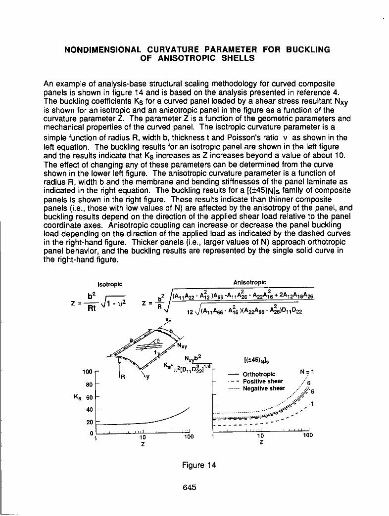
NONDIMENSIONAL CURVATURE PARAMETER FOR BUCKLINGOF ANISOTROPIC SHELLS
An example of analysis-base structural scaling methodology for curved compositepanels is shown in figure 14 and is based on the analysis presented in reference 4.
The buckling coefficients Ks for a curved panel loaded by a shear stress resultant Nxyis shown for an isotropic and an anisotropic panel in the figure as a function of thecurvature parameter Z. The parameter Z is a function of the geometric parameters andmechanical properties of the curved panel. The isotropic curvature parameter is a
simple function of radius R, width b, thickness t and Poisson's ratio v as shown in theleft equation. The buckling results for an isotropic panel are shown in the left figureand the results indicate that Ks increases as Z increases beyond a value of about 10.
The effect of changing any of these parameters can be determined from the curveshown in the lower left figure. The anisotropic curvature parameter is a function ofradius R, width b and the membrane and bending stiffnesses of the panel laminate asindicated in the right equation. The buckling results for a [(+45)N]s family of compositepanels is shown in the right figure. These results indicate than thinner compositepanels (i.e., those with low values of N) are affected by the anisotropy of the panel, andbuckling results depend on the direction of the applied shear load relative to the panelcoordinate axes. Anisotropic coupling can increase or decrease the panel bucklingload depending on the direction of the applied load as indicated by the dashed curvesin the right-hand figure. Thicker panels (i.e., larger values of N) approach orthotropicpanel behavior, and the buckling results are represented by the single solid curve inthe right-hand figure.
Experiments will be conducted as part of the Langley composite fuselage shellstructures program to understand the response and failure characteristics of stiffenedpanels, stiffened shells and structural elements for the panels and shells. Full-scaletechnology benchmark curved stiffened panels from the Langley AdvancedComposites Technology (ACT) program will be tested to verify the behavior ofcandidate shell design concepts and half-scale pathfinder stiffened shells will besubjected to combined internal pressure and mechanical loads to identify and verifyshell behavioral characteristics that cannot be studied at a panel level. These
experiments will also be used to verify structural scaling methodology for compositeshell structures.
Experiments to understand response and failure of stiffenedshells, panels and elements
• Benchmark curved stiffened panels
• Pathfinder stiffened shell structures
• Experiments to verify scaling methodology
Figure 15
646
PRESSURE BOX
Stiffened panels subjected to combined hoop and axial loads will be tested in thepressure-box fixture shown schematically in figure 16. Internal pressure will beapplied to the panel which will generate hoop stress reactions where the panel isattached to the fixture. Hydraulic actuators will be used to generate the axial stresses.
Frame
Stringer
Air pressure(to be connectedto a plenum for
rupture studies) 2
,J
Hydraulic actuators
Figure 16
647
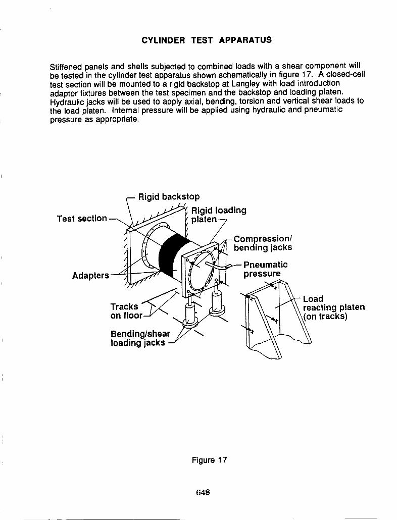
CYLINDER TEST APPARATUS
Stiffened panels and shells subjected to combined loads with a shear component willbe tested in the cylinder test apparatus shown schematically in figure 17. A closed-celltest section will be mounted to a rigid backstop at Langley with load introductionadaptor fixtures between the test specimen and the backstop and loading platen.Hydraulic jacks will be used to apply axial, bending, torsion and vertical shear loads tothe load platen. Internal pressure will be applied using hydraulic and pneumaticpressure as appropriate.
Test section
Adapt
Rigid backstop
Rigid loadingplaten
Compression/bending jacks
Trackson floor
Bending/shearloading jacks
Pneumatic
pressure
Le°:di n g platen
n tracks)
Figure 17
648
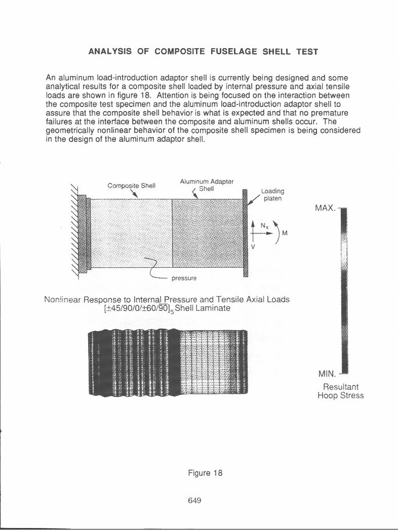
ANALYSIS OF COMPOSITE FUSELAGE SHELL TEST
An aluminum load-introduction adaptor shell is currently being designed and some analytical results for a composite shell loaded by internal pressure and axial tensile loads are shown in figure 18. Attention is being focused on the interaction between the composite test specimen and the aluminum load-introduction adaptor shell to assure that the composite shell behavior is what is expected and that no premature failures at the interface between the composite and aluminum shells occur. The geometrically nonlinear behavior of the composite shell specimen is being considered in the design of the aluminum adaptor shell.
Nonlinear Response to lnternai Pressure and Tensile Axial Loads [~45/90/0/~0/~] She 1 i Lam inate
MAX.
MIN. Resultant
Hoop Stress
Figure 18
649
D-BOX FOR CURVED PANEL TESTS
Large-scale curved stiffened panels subjected to combined loads with a shearcomponent will be tested in the closed-cell D-shaped box fixture shown schematicallyin figure 19. The test panel will be attached to a larger load-introduction or "dummy"panel with the same radius of the test specimen. Analytical studies of the test paneland load-introduction panel configuration will be conducted to quantify the test panelloading including the shear stress resultant Nxy and the normal stress resultants andloads in the skin, axial stiffeners and frames Nskin, Ns, and Nf, respectively.
Test panel
Dummy panel
Edgereinforcement
Circumferential
reinforcementM
Vl D-box
T
t- Backstop
Figure 19
650
DAMAGE TOLERANCE AND PRESSURE CONTAINMENT FORTHIN-WALLED COMPOSITE SHELL STRUCTURES
Damage tolerance studies in the Langley composite fuselage shell structures researchprogram will focus on low-energy impact damage and crack growth issues and alimited assessment of high-energy impact damage issues will also be conducted. Forlow-energy impact damage, a study is being conducted to determine the level ofimpact damage necessary to cause leaks to occur in thin-walled pressurizedcomposite shells. Studies will be conducted to determine the residual strength oflocally damaged shell structures that are subjected to combined internal pressure andmechanical loads. Damage growth characteristics will be identified for curvedstiffened panels and shells to help identify critical damage parameters. Damagecontainment concepts will be developed and evaluated to help provide safer designs.The results of the studies should help define damage tolerance design criteria for thin-walled shells that leak before they burst. A limited high-energy impact damage studywill also be conducted to assess the sensitivity of pressurized composite shellstructures to very severe damage conditions.
• Low-energy impact damage and cracks
Determine damage necessary to cause leaks in pressurizedshells
Determine residual strength of damaged panels and shellssubjected to combined loadsDetermine damage growth characteristics and critical damageparametersEvaluate damage containment conceptsDetermine damage-tolerance and leak-before-burst criteria
• High-energy impact damage
Assess sensitivity of pressurized composite shell structures tohigh-energy impact damage
Figure 20
651
EFFECTS OF SLITS ON FAILURE OF COMPOSITE SHELLS SUBJECTEDTO INTERNAL PRESSURE
Some results of a study of the effects of damage on the burst strength of 12-inch-diameter graphite-epoxy cylindrical shells are shown in figure 21. These results wereobtained by Massachusetts Institute of Technology under NASA grant NAG1-991 andare reported in reference 5. Thirty-inch-long unstiffened cylinders with [90/0/+45]s,
[+45/0]s or [+45/90]s laminates were pressurized to failure with slits of length 2amachined into the shell at midlength. The figure shows that the burst pressure of theshells decreases as the slit length 2a increases and that laminate stacking sequenceaffects the burst strength.
• AS4/3501-6
graphite-epoxy
• Diameter: 12 in.
Burst
pressure,p, psi
• Length: 30 in.
• Thickness
0.034 in. (6-ply laminates)0.042 in. (8-ply laminate)
400
300
200
100
0
m
m
m
m
m
0 [90/0/:_45] s0
[] [,45/0] s[]
Z_ [±45/90] s
A []
I I I I
1 2
Slit length, 2a, in.
I
3
Figure 21
652
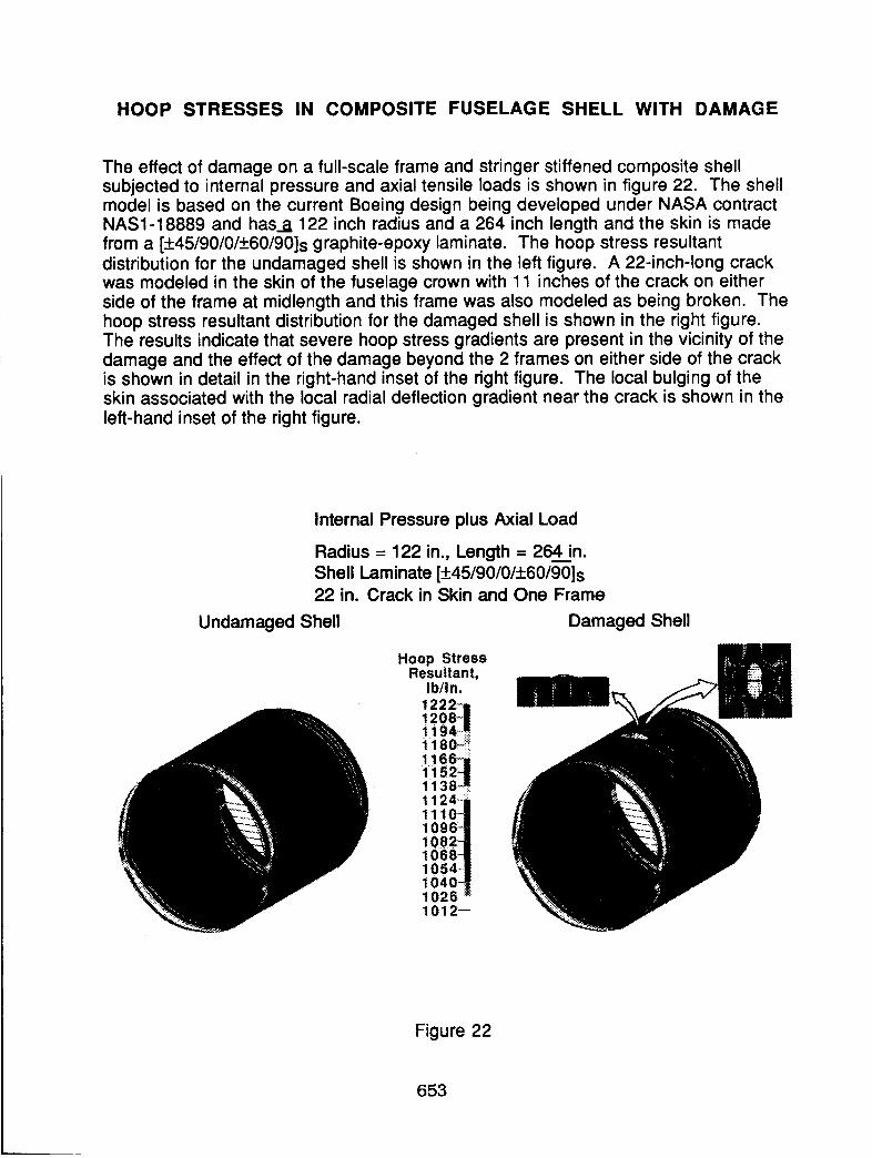
HOOP STRESSES IN COMPOSITE FUSELAGE SHELL WITH DAMAGE
The effect of damage on a full-scale frame and stringer stiffened composite shellsubjected to internal pressure and axial tensile loads is shown in figure 22. The shellmodel is based on the current Boeing design being developed under NASA contractNAS1-18889 and has__ 122 inch radius and a 264 inch length and the skin is made
from a [+45/90/0/+60/90]s graphite-epoxy laminate. The hoop stress resultantdistribution for the undamaged shell is shown in the left figure. A 22-inch-long crackwas modeled in the skin of the fuselage crown with 11 inches of the crack on eitherside of the frame at midlength and this frame was also modeled as being broken. Thehoop stress resultant distribution for the damaged shell is shown in the right figure.The results indicate that severe hoop stress gradients are present in the vicinity of the
damage and the effect of the damage beyond the 2 frames on either side of the crackis shown in detail in the right-hand inset of the right figure. The local bulging of theskin associated with the local radial deflection gradient near the crack is shown in the
left-hand inset of the right figure.
Internal Pressure plus Axial Load
Radius = 122 in., Length = 264.._iin.
Shell Laminate [+45/90/0/+60/90]s
22 in. Crack in Skin and One Frame
Undamaged Shell Damaged Shell
Hoop StressResultant,
Ib/in.
1222-1=1208-111 i 94---_1180 -_1166-11152-11138 J1124--- I1110-11096-11082-11068-1110541104011026_1012--
Figure 22
653
COMPOSITE FUSELAGE SHELL STRUCTURES RESEARCH
The principal activities for the Langley composite fuselage shell structures research
program are shown in figure 23 by fiscal year from FY92 to FY95.
Principal Activities by Fiscal Year
FY92• Develop and evaluate panel and shell
concepts and designs• Analyze response of panels with design
details and conduct design studies• Test panels for effects of discontinuities,
impact damage, and internal pressure
FY93• Conduct nonlinear analyses and design
studies for panels and shells• Test panels subjected to combined loads
for response and failure mechanisms• Analyze response of panels and shells with
design details and combined loads• Test shells for effects of discontinuities,
impact damage
FY94-FY95
• Test shells subjected to combined loadsfor response and failure mechanisms
• Verify damage containment analyses andconcepts for pressurized shells
• Verify scaling methodology for panels andshells and conduct nonlinear analyses
Nx0 J
Figure 23
654
COMPOSITE FUSELAGE SHELL STRUCTURES RESEARCH SCHEDULE
The planned schedule for the Langley composite fuselage shell structures program isshown in figure 24 through fiscal year FY95.
FY 92 FY 93
V V
_Combined Load Test System /
FY 94 FY 95
Pressure D-box/box shell
V V
IShell/Panel Analysis and Design1st Shell
Design
V V
Panel Fabrication and Test
Crown KeelPanels Panels
V
2nd Shell
Design
V
SidePanels
I Subscale barrel section fabrication and test
V
1st Shell 2nd Shell
Figure 24
655
CONCLUDING REMARKS
The composite fuselage shell structures research program at the NASA LangleyResearch Center will develop verified structural mechanics methodologies for reliablypredicting the response and failure of composite frame- and stringer-stiffened shellstructures and curved stiffened panels subjected to combined internal pressure andmechanical loads and to local damage. The mechanical loads will includecompression, tension, bending, vertical shear and torsional loads. Structural analysismethods that predict the nonlinear response and failure of composite fuselage shellstructures subjected to combined loads will be developed and applied to candidateshell designs. Geometrically nonlinear behavior associated with the effects of internalpressure on skin deformation and postbuckling behavior will be included in theanalysis and design of candidate shell structures. Structural details, discontinuitiesand eccentricities that generate local stress and deformation gradients and theinteraction between the subcomponents of stiffened shell structure will be studied inthe program. Structural sizing procedures that provide minimum-weight designs forstiffened composite fuselage shells subjected to combined loads will be developedand used to conduct parametric studies to determine the sensitivity of the shellbehavior to changes in structural parameters. Structural scaling methodology will bedeveloped for composite fuselage shells subjected to combined loads to relate full-scale designs to half-scale and quarter-scale models of these designs. Tests will beconducted on technology benchmark curved stiffened panels and pathfinder stiffenedshells to identify critical failure mechanisms, to verify structural analysis methods, andto understand the effects of local gradients and local damage on composite shellbehavior. Studies will be conducted to determine the damage tolerance andpropagation characteristics and residual strength of damaged composite stiffenedshells subjected to combined internal pressure and mechanical loads and damagecontainment concepts will be explored. The Langley composite fuselage shellstructures research program will contribute to the development of the structurestechnology necessary to develop full-scale pressurized composite stiffened fuselagestructures for future transport aircraft.
REFERENCES
o
.
,
.
.
Boitnott, R. L.; Starnes, J. H., Jr.; and Johnson, E. R.: Nonlinear Response ofInternally Pressurized Graphite-Epoxy Cylindrical Panels.AIAA Paper No. 84-0955, May 1984.
Hyer, M. W.; Loup, D. C.; and Starnes, J. H., Jr.: Stiffener/Skin Interactions inPressure-Loaded Composite Panels. AIAA Journal, Vol. 28, No. 3, March 1990,pp. 532-537.
Hyer, M. W.; and Cohen, D.: Calculation of Stresses and Forces Between Skin andStiffener in Composite Panels. AIAA Journal, Vol. 26, No. 7, July 1988,pp. 852-857.
Nemeth, M. P.: Nondimensional Parameters and Equations for Buckling ofSymmetrically Laminated Thin Elastic Shallow Shells. NASA TM 104060,March 1991.
Ranniger, C. U.: Damage Tolerance and Arrest Characteristics of PressurizedGraphite/Epoxy Tape Cylinders. M. S. Thesis, Massachusetts Institute ofTechnology, June 1991. TELAC Report 91-11.