TRANSPORTATION RESEARCH RECORD 1119 139 Nailed-Soil Retaining Structures: Design and Practice lLAN JURAN Soil nailing is an in situ soil reinforcement technique that has been used during the last two decades, mainly in France and Germany, to retain excavations or stablllze slopes. The funda- mental concept of soil nailing is the reinforcement of the ground by passive inclusions, closely spaced, to increase the overall shear strength of the in situ soil, to restrain its displace- ments, and to limit its decompression during and after excava- tion. The technology, construction process, design methods, and fundamental aspects of behavior and soil-nail interaction in nailed-soil retaining structures are discussed. Soil nailing is an extension of the "new Austrian Tunneling Method" (1), which combines reinforced shotcrete and rock- bolting to provide a flexible support system for the construction of underground excavations. However, its rapid development has been considerably enhanced by the increasing use of the Reinforced Earth® technique in mountainous areas. Soil nailing has been used in a variety of civil engineering projects including stabilization of railroad and highway slopes (2,3), construction of retaining structures for excavations as deep as 30 m (4-8), and tunneling and other civil and industrial projects (9). Typical applications are shown in Figure 1. As demonstrated by Gassler and Gudehus (10), nailed-soil retain- ing structures can withstand both static and dynamic vertical loads at their upper surface without excessive displacements. In this paper are presented the technology, construction pro- cess, design methods, and fundamental aspects of behavior and soil-nail interaction in nailed-soil retaining structures. A shorter version of this paper has been published elsewhere ( 11 ). TECHNOLOGY, STRUCTURAL ELEMENTS, AND CONSTRUCTION PROCESS The main components of a nailed-soil retaining structure are the in situ ground, the resisting inclusions, and the facing. The economy of the system is predominantly dependent on the technology and construction rate. The technology of soil nail- ing is flexible, and both the structural elements (inclusions and facing) and installation techniques can be easily adapted, even during construction, to provide iQe most appropriate engineer- ing solution for specific site conditions and soil profiles. To date, soil nailing has been used primarily in temporary retain- ing structures. Concerns about permanent nailed-soil systems are the durability of metallic inclusions in the ground and the Department of Civil Engineering, Louisiana State University, Baton Rouge, La. 70803. Permanent affiliation: Ecole" Nationale des Ponts et Chaussees, Paris, France. shortcomings of facing technology. Therefore, in recent years, technological developments have been mainly focused on pro- ducing low-cost, corrosion-protected nails and prefabricated concrete or steel panels that provide a more appropriate re- sponse to different aesthetic, environmental, and durability requirements. Inclusions and Installation Techniques The steel reinforcing elements currently used can be mainly classified as (a) driven nails, (b) grouted nails, (c) jet-grouted nails, and (d) encapsulated corrosion-protected nails. Driven Nails Driven nails, commonly used in France and Germany, are generally low-cost, small-diameter (15 to 46 mm) rods or bars, or metallic profiles, made of mild steel with a yield strength of 350 MPa (50 ksi). They are closely spaced (2 to 4 bars per square meter) and create a rather homogenous composite rein- forced soil mass. The nails are driven into the ground at the designed inclina- tion using a vibropercussion pneumatic or hydraulic hammer with no preliminary drilling. Special nails with an axial channel can be used to allow for grout sealing of the nail to the surrounding soil after its complete penetration. This installation technique is rapid and economical (4 to 6 bars per hour). However, it is limited by the length of the bars (maximum length about 20 m) and by the heterogeneity of the ground (e.g., boulders). Grouted Nails Grouted nails are generally high-strength steel bars (15 to 46 mm in diameter) with a yield strength of 1050 MPa (150 ksi). They are placed in boreholes (10 to 15 cm in diameter) with a vertical and horizontal spacing varying typically from 1 to 3 m, depending on the type of soil. The nails are conventionally cement or resin grouted by gravity or under low pressure. Ribbed bars can be used to improve the nail-grout adherence, and special perforated tubes have been developed to allow injection of grout through the inclusion. Jet-Grouted Nails Jet-grouted nails are composite inclusions made of a grouted soil with a central steel rod that can be as thick as 30 to 40 cm.
Transcript
TRANSPORTATION RESEARCH RECORD 1119 139
Nailed-Soil Retaining Structures: Design and Practice
lLAN JURAN
Soil nailing is an in situ soil reinforcement technique that has been used during the last two decades, mainly in France and Germany, to retain excavations or stablllze slopes. The fundamental concept of soil nailing is the reinforcement of the ground by passive inclusions, closely spaced, to increase the overall shear strength of the in situ soil, to restrain its displacements, and to limit its decompression during and after excavation. The technology, construction process, design methods, and fundamental aspects of behavior and soil-nail interaction in nailed-soil retaining structures are discussed.
Soil nailing is an extension of the "new Austrian Tunneling Method" (1), which combines reinforced shotcrete and rockbolting to provide a flexible support system for the construction of underground excavations. However, its rapid development has been considerably enhanced by the increasing use of the Reinforced Earth® technique in mountainous areas.
Soil nailing has been used in a variety of civil engineering projects including stabilization of railroad and highway slopes (2,3), construction of retaining structures for excavations as deep as 30 m (4-8), and tunneling and other civil and industrial projects (9). Typical applications are shown in Figure 1. As demonstrated by Gassler and Gudehus (10), nailed-soil retaining structures can withstand both static and dynamic vertical loads at their upper surface without excessive displacements.
In this paper are presented the technology, construction process, design methods, and fundamental aspects of behavior and soil-nail interaction in nailed-soil retaining structures. A shorter version of this paper has been published elsewhere ( 11 ).
TECHNOLOGY, STRUCTURAL ELEMENTS, AND CONSTRUCTION PROCESS
The main components of a nailed-soil retaining structure are the in situ ground, the resisting inclusions, and the facing. The economy of the system is predominantly dependent on the technology and construction rate. The technology of soil nailing is flexible, and both the structural elements (inclusions and facing) and installation techniques can be easily adapted, even during construction, to provide iQe most appropriate engineering solution for specific site conditions and soil profiles. To date, soil nailing has been used primarily in temporary retaining structures. Concerns about permanent nailed-soil systems are the durability of metallic inclusions in the ground and the
Department of Civil Engineering, Louisiana State University, Baton Rouge, La. 70803. Permanent affiliation: Ecole" Nationale des Ponts et Chaussees, Paris, France.
shortcomings of facing technology. Therefore, in recent years, technological developments have been mainly focused on producing low-cost, corrosion-protected nails and prefabricated concrete or steel panels that provide a more appropriate response to different aesthetic, environmental, and durability requirements.
Inclusions and Installation Techniques
The steel reinforcing elements currently used can be mainly classified as (a) driven nails, (b) grouted nails, (c) jet-grouted nails, and (d) encapsulated corrosion-protected nails.
Driven Nails
Driven nails, commonly used in France and Germany, are generally low-cost, small-diameter (15 to 46 mm) rods or bars, or metallic profiles, made of mild steel with a yield strength of 350 MPa (50 ksi). They are closely spaced (2 to 4 bars per square meter) and create a rather homogenous composite reinforced soil mass.
The nails are driven into the ground at the designed inclination using a vibropercussion pneumatic or hydraulic hammer with no preliminary drilling. Special nails with an axial channel can be used to allow for grout sealing of the nail to the surrounding soil after its complete penetration. This installation technique is rapid and economical (4 to 6 bars per hour). However, it is limited by the length of the bars (maximum length about 20 m) and by the heterogeneity of the ground (e.g., boulders).
Grouted Nails
Grouted nails are generally high-strength steel bars (15 to 46 mm in diameter) with a yield strength of 1050 MPa (150 ksi). They are placed in boreholes (10 to 15 cm in diameter) with a vertical and horizontal spacing varying typically from 1 to 3 m, depending on the type of soil. The nails are conventionally cement or resin grouted by gravity or under low pressure. Ribbed bars can be used to improve the nail-grout adherence, and special perforated tubes have been developed to allow injection of grout through the inclusion.
Jet-Grouted Nails
Jet-grouted nails are composite inclusions made of a grouted soil with a central steel rod that can be as thick as 30 to 40 cm.
140 TRANSPORTATION RESEARCH RECORD 1119
- - - '"'"'(;";..,..
-·s: .·.: ., =t--'ffi""' - - -vT~"<7!7
.. -RETAINING STRUCTURES SLOPE STABILIZATION
TUNNELING
al CONVENTIONAL METHOD
DECREASE OF THE / CONFINING PRESSURE I
tr, : 0 I
REINFORCED CONCRETE
,,. /
/
--~ I
bl AUSTRIAN TUNNELING METHOD
ANCHOR PIN
INCREASE OF THE CONFINING PRESSURE
tr, : Pi
MESH REINFORCEMENT
SHOTCRETE
tr,: CONFINING PRESSURE AT FACING
Pi• INITIAL PRESSURE
FIGURE 1 Main applications of soil nailing.
A technique that combines vibropercussion driving and highpressure (> 20 MPa) jet grouting has recently been developed and patented by Louis (9). The nails are installed (Figure 2) using a high-frequency (up to 70 Hz) vibropercussion hammer, and cement or resin grouting can be performed either during or after installation. The grout is injected through a small-
I. VIBRO-PRECUSSION HAMMER 2 SLIDING SUPPORT 3 . REINFORCEMENT TO BE INSERTED 4. SLIDING GUIDE 5. FIXED GUIDE 6. SOIL TO BE TREATED
FIGURE 2 Jet nailing: Installation of reinforcing elements with or without simultaneous grouting (C. Louis, unpublished results, 1985).
diameter (few millimeters) longitudinal channel in the reinforcing rod under a pressure that is sufficiently high to cause hydraulic fracturing of the surrounding ground. However, for current applications, nailing with a significantly lower grouting pressure ("' 4 MPa) has been successfully used, particularly in granular soils. The jet-grouting installation technique provides recompaction and improvement of the surrounding ground and increases significantly the shear and pullout resistances of the composite inclusion.
Corrosion-Protected Nails
Corrosion-protected nails have been developed recently by French contractors (illtrafor-Cofor; Solrenfor) to be used in permanent structures. ill this type of inclusion, the steel bars are enclosed in grout to protect against water penetration. In the Solrenfor nail (Figure 3a), the steel bar and the surrounding grout are protected by casing made of steel or plastic. ill the illtrafor-Cofor nail (Figure 3b), the prestressing effect maintains the grout under compression and thus keeps it from microcracking. However, other doubly encapsulated nails similar in concept to the technology used in earth anchors could be
used. ill American practice, contractors have proposed and used resin-bonded epoxy nails to achieve double protection.
Juran 141
LONGITUDINAL SECTION
PROTECTIVE TUBE
~ ONJErnoN HOLES WELO<NG
·./~ (a)
STEEL CABLES (b)
STEEL REINFORCING BAR
GROUTING
MANCHETTE
FIGURE 3 TBHA nail developed and patented by Solrenfor for permanent structures (a) and prestressed multireinforced nail, Intrapac, developed by lntrafor-Cofor (b).
Facing
The main functions of the facing are to ensure the stability of the local ground between the reinforcement layers, to limit its decompression immediately after excavation, and to protect the ground from surface erosion and weathering effects. Therefore the facing has to be continuous, fit the irregularities of the cut slope surface, and be flexible enough to withstand ground displacement during excavation. Depending on the application and soil type, four kinds of facing are presently used.
Sfwtcrete Facing
Shotcrete facing (10 to 25 cm thick) is currently used for most temporary retaining structures in soils. This facing technology provides a continuous, flexible surface layer that can fill voids and cracks in the surrounding ground. It is generally reinforced with a welded wire mesh and its required thickness is obtained by successive layers of shotcrete (each 9 to 12 cm thick). This technique is relatively simple and inexpensive, but it does not generally provide the technical quality and the aesthetic aspect required for permanent structures. In particular, the durability of the shotcrete facing can be affected by groundwater, seepage, and environmental factors such as climatic changes and freezing, which may induce cracking. In addition, construction of a shotcrete facing makes provision of efficient drainage at the concrete-soil interface difficult.
Welded Wire Mesh
Welded wire mesh is generally used to provide a facing in fragmented rocks or intermediate soils (chalk, marl, shales).
Concrete and Steel Facings for Permanent Structures
Cast-in-place reinforced-concrete facing is, to date, most frequently used for permanent structures. However, prefabricated concrete or steel panels are now being developed for permanent structures. These panels can be designed to meet a variety of aesthetic, environmental, and durability criteria. They provide appropriate technical solutions for integrating continuous drainage behind the facing. Figure 4 (top) shows Solrenfor metallic panels for inclined facing (C. Louis, unpublished results). The rectangular steel panels are bolted together and the soil nailing is performed through their common corners. Figure 4 (bottom) shows prefabricated concrete panels with continuous geotextile drainage. Composite panels have also been used in association with prefabricated steel panels and cast-inplace concrete.
Grout nails are generally attached to the facing (mesh or shotcrete) by bolting the bars to a square steel plate (30 to 40 cm wide), whereas driven bars are generally attached to the facing by cladding or other suitable methods.
CONSTRUCTION PROCESS AND MONITORING
Construction of a nailed-soil retaining structure involves three main repetitive stages: (a) excavation of a limited height, (b) nailing and drainage, and (c) placing the facing. The technology and the construction process are fundamentally conceived to minimize disturbance of the ground during excavation, to limit its decompression, and to prevent deterioration of the original mechanical properties of the ground. Therefore the nailing system (facing and reinforcement) has to be placed as quickly as possible after excavation.
142
Excavation is done with small conventional earth-working equipment in typical incremental steps 1.5 to 3 m deep. In general, the short-term cohesion of the soil is sufficient to ensure local stability of each excavation step. The cut slope must be properly excavated to prevent local instabilities that could induce movement at the upper part of the nailed-soil wall.
Where there is groundwater, an appropriate drainage system should be provided to (a) protect the facing elements by shallow drainage (plastic pipes, 10 cm in diameter, 30 to 40 cm long) and (b) prevent saturation of the nailed ground, which can significantly affect the structure's displacements and cause instabilities during or after the excavation (slotted plastic tubes that are longer than the nails are generally used). In the case of permanent structures with prefabricated panels, a continuous drain such as a geotextile composite can be placed behind the facing.
Soil-nailing technology relies on passive inclusions, and a certain soil displacement is required to effectively mobilize the resisting forces. Therefore it has been essential to monitor actual structures, to measure the facing displacements in different types of soils, and to verify that they are compatible with design criteria for admissible displacements.
BEHAVIOR AND DESIGN OF NAILED-SOIL RETAINING STRUCTURES
Soil-Reinforcement Interaction
The soil-reinforcement interaction in nailed-soil retaining structures involves two fundamental mechanisms: (a) lateral friction and (b) passive soil thrust on relatively rigid inclusions. The small-diameter inclusions, which are generally used in soil nailing, are relatively flexible. Therefore the soil displacement required to mobilize the normal passive soil thrust on the inclusion is substantially greater than that required to generate lateral friction at the soil-inclusion interface. For a given structurai geometry and soii profiie, the mobiiized interaction mechanism depends mainly on the construction process and installation techniques, the bending stiffness of the inclusion, and its inclination with respect to the potential failure surface.
Lateral Friction
The mobilization of lateral friction along inclusions (piles, reinforcing elements, etc.) has already been extensively studied. Both laboratory studies and pullout tests on actual Reinforced Earth walls have provided experimental data for the evaluation of the effect of various parameters (surface characteristics of the reinforcement, rib effect, density and dilatancy properties of the soil, type and amount of fines, normal stress on the inclusion, etc.) on the apparent soil-to-reinforcement friction coefficient ( 12-15). These experimental results are presently used in design guidelines for Reinforced Earth retaining structures (16). The principles of frictional soil-reinforcement interaction in reinforced embankments and nailed-soil walls are apparently similar. Consequently, an attempt has been made by Cartier and Gigan (7) to correlate the results of fullscale pullout tests on actual nails with design recommendations for Reinforced Earth structures. The results of full-scale pullout
TRANSPORTATION RESEARCH RECORD 1119
FIGURE 4 Prefabricated steel panels (top) and prefabricated concrete panels and nail connections (bottom).
tests performed by Cartier and Gigan (7) have shown (Figure 5) that the apparent friction coefficient(µ*) between a driven nail and a granular soil corresponds to that used in the design guidelines for Reinforced Earth walls. However, as indicated by different authors (17,18), the mobilization of soil-to-reinforcement friction is highly dependent on the technique used to install the inclusions. In a Reinforced Earth wall the soil is
0 10 20 0
r.1 (KN/m )
A~[ •
T.1 AVERAGE 17KN/m./
5 ~ .
10 T A~ •
Z(ml
SOIL : SAND ¢'33° t' IOkPo NAILS: DRIVEN PROFILE
5
10
Z(m)
2 µ•
••
SPECIFICATIONS FOR • REINFORCED EARTH
• TAN cf>
FIGURES Soll reinforcement friction between a driven nail and a granular soil (7).
Juran
compacted around the inclusion and is practically at a K 0 state of stress, whereas in nailed ground the drilling of the borehole for the grouted nail produces an unloading of the disturbed surrounding soil that can significantly affect its mechanical properties. In the latter case, the soil-inclusion friction is governed by soil recompaction due to grouting and the characteristics of the soil-grout interfaces are quite different from those of metallic surfaces in Reinforced Earth walls. In addition, the granular backfill material generally used in Reinforced Earth walls is rather uniform and can be significantly different from the ground to be nailed. Therefore, design guidelines for Reinforced Earth walls should not be extrapolated to nailed-soil structures, and pullout tests are required to obtain a reliable estimate of the limit lateral interface shear stress (or the apparent friction coefficient).
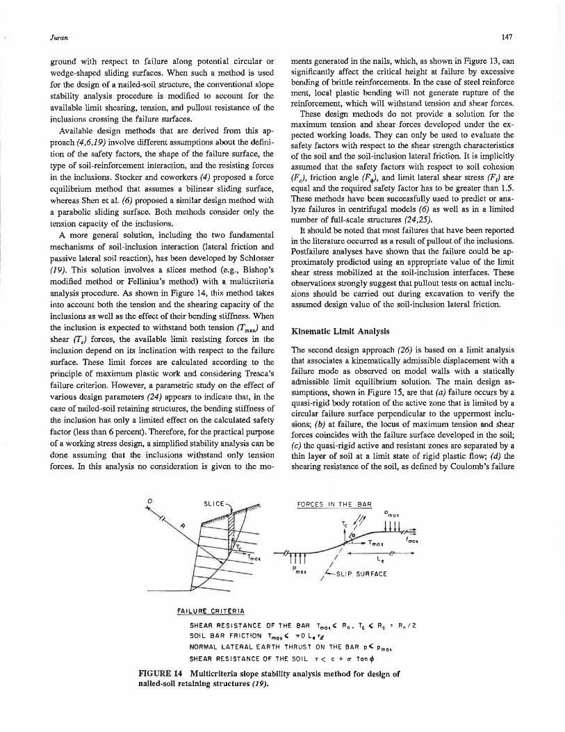
In soil nailing it is practical to use design parameters derived from the results of in situ tests. Guilloux and Schlosser (18) have shown (Figure 6) that empirical design methods for fric-
TJ?(kPol MEASURED
600 0--
DILATANT MORAINE 500
400
()...()
300 MARLY CALCAREOUS
200 •DRIVEN BARS
o GROUTED BARS 100 SAND IN BOREHOLE
SILT C AY
I 00 200 300 400 500 PREDICTED rl (kPol
FIGURE 6 Comparison of measured soil-bar lateral friction and design guidelines for friction piles using pressuremeter test results (18).
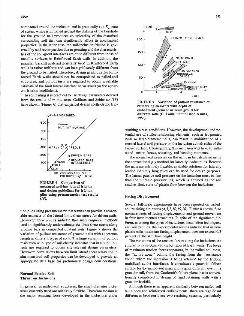
tion piles using pressuremeter test results can provide a reasonable estimate of the lateral limit shear stress for driven nails. However, their results indicate that such empirical methods tend to significantly underestimate the limit shear stress along grouted bars in compacted dilatant soils. Figure 7 shows the variation of pullout resistance of grouted nails with adherence length in different types of soils. The large variation of pullout resistance with type of soil clearly indicates that in situ pullout tests are required to obtain site-relevant design parameters. However, correlations between limit lateral shear stress and in situ measured soil properties can be developed to provide an appropriate data base for preliminary design considerations.
Normal Passive Soll Thrust on Inclusions
In general, in nailed-soil structures, the small-diameter inclusions currently used are relatively flexible. Therefore tension is the major resisting force developed in the inclusions under
T (KN) T ·I m-hw D= 2"
200 . 100 KN/M LITTLE CHALK
150
100
50
0 Lim)
FIGURE 7 Variation of pullout resistance of reinforcing elements with depth of embedment (cement or resin grout) for different soils (C. Louis, unpublished results, 1985).
143
working stress conditions. However, the development and potential use of stiffer reinforcing elements, such as jet-grouted nails or large-diameter nails, can result in mobilization of a normal lateral soil pressure on the inclusion at both sides of the failure surface. Consequently, this inclusion will have to withstand tension forces, shearing, and bending moments.
The normal soil pressure on the nail can be calculated using the conventional p-y method for laterally loaded piles. Because the nails are relatively flexible, available solutions for laterally loaded infinitely long piles can be used for design purposes. The lateral passive soil pressure on the inclusion must be less than the ultimate pressure (p), which is attained as the soil reaches limit state of plastic flow between the inclusions.
Facing Displacement
Several full-scale experiments have been reported on nailedsoil retaining structures (4,5,7,10,19,20). Figure 8 shows field measurements of facing displacements and ground movement in four instrumented structures. In spite of the significant differences among the types of inclusions, installation techniques, and soil profiles, the experimental results indicate that in nonplastic soils maximum facing displacement does not exceed 0.3 percent of the structure height.
The variations of the tension forces along the inclusions are similar to those observed on Reinforced Earth walls. The locus of maximum tension forces separates, in the nailed-soil mass, the "active zone" behind the facing from the "resistance zone" where the inclusion is being retained by the friction mobilized at the interfaces. It constitutes a potential failure surface for the nailed-soil mass and is quite different, even in a granular soil, from the Coulomb's failure plane that is conventionally considered in design of rigid retaining walls with a granular backfill.
Although there is an apparent similarity between nailed-soil cut slopes and reinforced embankments, there are significant differences between these two retaining systems, particularly
144
• .. •
• ~
g; e I- .s z _J w _J
~ Cl
30
~ 3: 20 Cl w _J J: Q. II/) -u. Co _J Q.
Cl 0 10 ~l-ow NJ: a: lo J:
SOIL
Medium sand
Silty sand (SM)
Fine sand (SP) to clayey sand (SC)
Residual clayey silt
TRANSPORTATION RESEARCH RECORD 1119
5 10 15 WALL HEIGHT (m)
NAIL REFERENCE
driven Gassler et al., (1981)
grouted Shen et al.• (1981)
driven Cartier & Gigan (1983)
weathered shale, sandstone grouted Juran & Elias (1986)
Fon~ainbleau Sand (SP) grouted Plumelle (1986)
FIGURE 8 Horizontal displacement of nailed-soil walls.
(a) the construction process, (b) the installation technique used for the inclusion, ( c) the inclination of the inclusion and of the facing, and (d) the bending stiffness of the inclusion.
embankment) result in a significantly different displacement mode of the facing and stress history of the retained soil. Figure 9 shows the maximum tension forces measured in a Reinforced Earth wall (21) and in a nailed-soil wall (7) with driven nails in granular ground. In both structures. the reinforcement tends to maintain the retained soil in a K
0 state of stress; however, the
differences in construction process lead to quite different distributions of the maximum tension forces with depth. Reducedscale laboratory model tests performed by Juran and coworkers
Effect of Construction Process
The substantial differences between the construction process for nailed-soil and Reinforced Earth walls (excavation versus
a FAILURE SURFACE IN THE SOIL • LOCUS OF INCLUSIONS BREAKAGE
Finite element analysis Laboratory model
FIGURE 10 Effect of Inclination of Inclusions on facing displacement and on locus of maximum tension forces (22).
(22) indicated that these distributions are associated with two different displacement modes of the facing .
Inclination of Inclusions
Inclination of the inclusions may be an important design parameter. Laboratory model studies and finite element analyses (23) have indicated (Figure 10) that the locus of maximum tension forces in the inclusions and the failure surface in the soil are practically perpendicular to the inclusions at the upper part of the structure. Consequently, inclining the inclusion downward leads ·to a larger potential failure surface and re-
0
' ' '
Maximum tension force
01 02
'\ ''"" 0,2 \ · ~,
\ '~ \ \'\_
0,4
\ \"Ko 0,6 o.~ , cf \ ·~ "'-
•- ~ . 2cf Ka \ '
0,11
\ '11.
1,0
Z/H t.35° 1 H • 68 cm
03
s •• 5 cm s .• 25cm
Reinforced Earth model wall
duces the pullout resistance of the inclusions. These studies also showed that increasing the inclination of the reinforcement results in a significant increase of the facing displacement (Figure 10). The effect of the inclination of the reinforcement on the tension forces generated in the inclusions depends primarily on the construction process. As shown in Figure 11, in a Reinforced Earth model wall the inclination of the reinforcement results in a decrease of maximum tension forces, which approach the Ka line of the active earth pressure distribution, whereas in a nailed-soil model wall the increase of the facing displacement during excavation is associated with an increase of tension forces in the nails. However, within the range of inclinations encountered in practice (J3 = 10 to 20 degrees) the effect of inclination on tension forces is not significant.
Maximum tension force
0 01 02 3
Tmax
5 . H. ~ • . S,
0 - ~ • o·
0,4 r>. 20·
0,6 "' Ko
" \
0,11 \ 1,0 ¢:~5· H. 72 cm
ZIH s . : 5cm s,: 25 cm
Soll Nailing model wall
FIGURE 11 Effect of inclination of inclusions on maximum tension forces (22); commas should be read as decimals.
146
0 0102 0 OJ 0 .2 03 04 0/H 0/H
• 0 0 02 02
0 • 04 • 04
06 06
0,5
1.0 10 Z/H Z/H
o FAILURE SURFACE IN THE SOIL
1
06 ? '
O.B 6 1.0 Z/H
TRANSPORTATION RESEARCH RECORD 1119
r .....
RIGID 1 INCLUSIONS
/'-...FLEXIBLE d INCLUSIONS
e LOCUS OF INCLUSIONS BREAKAGE
FIGURE 12 Effect of bending stiffness of Inclusions on maximum tension forces and on failure of nailed-soil model walls (22).
Bending Stiffness
Bending stiffness can significantly affect the mobilized resisting forces and the failure mechanism. Its effect on nail forces is highly dependent on the inclination of the inclusion with re-spect to the potential failure surface. The small-di~9!1eter nails presently used are relatively flexible. However, installation techniques such as jet grouting lead to the introduction of highstrength composite grouted inclusions that can be quite stiff. As indicated previously, the soil displacement required to mobilize the shear resistance and bending stiffn,ess is significantly larger than that required to generate tension forces. Therefore, as long as the soil displacements are relatively small, the bending stiffness of the inclusions has practically no effect on the behavior of the structure. Both laboratory model tests and finite element analyses (23) have shown (Figure 12) that, under working stress conditions, the shear forces (Tcj mobilized in the inclusions are relatively small (T/Tmax. < 10 percent) and have practically no influence on the locus and values of maximum tension forces (T max.) .
The laboratory model tests have also demonstrated (Figure 13) that, at failure by breakage of the inclusions, increasing their bending stiffness results in a significant decrease of the
80
70 f--:i:
60 \!>
w 50 :i:
..J 40 ~ l.' f--
30
er 20 u
10
0 I 2 3 b,boq (cml
WIDTH OF INCLUSIONS
FIGURE 13 Effect of bending stiffness on failure height of a nailed-soil model wall (22).
critical failure height of the model wall. In these models, the polystyrene strips (6 mm thick) have the same tension resistance (Rrb: b ==width of the strips) as the aluminum strips (15 µm thick) but a significantly larger bending stiffness, which depends on their vertical or horizontal position. As is shown in Figure 12, in the case of failure hy excessive bending of the inclusions, the locus of breakage points (points of maximum bending) is located behind the failure surface in the soil. The bending stiffness appears to have practically no effect on the failure surface in the soil, which corresponds to the locus of maximum tension and shear forces in the inclusions. However, further research is required to develop a better understanding of the potential effect of reinforcement bending stiffness on the behavior of nailed-soil structures.
DESIGN METHODS
The design criteria for nailed-soil structures include
• Stability with respect to the potential failure of the soil, the inclusion (excessive tension or bending), and their interaction (pullout failure or plastic flow of the soil between the inclusions);
• Admissible displacements with respect to expected performance of the structure;
• Durability requirements for permanent structures, particularly in aggressive environments;
• Environmental and architectural aspects; and • Design of the facing generally done after conventional
structural analysis.
Two fundamentally different design approaches have been developed: (a) modified slope stability analysis and (b) kinematic limit analysis.
Modified Slope Stability Analysis
The first design approach is based on rather conventional slope stability analysis procedures that have been adapted to evaluate the safety factor of the nailed-soil mass and the surrounding
Juran
ground with respect to failure along potential circular or wedge-shaped sliding surfaces. When such a method is used for the design of a nailed-soil structure, the conventional slope stability analysis procedure is modified to account for the available limit shearing, tension, and pullout resistance of the inclusions crossing the failure surfaces.
Available design methods that are derived from this approach (4,6,19) involve different assumptions about the definition of the safety factors, the shape of the failure surface, the type of soil-reinforcement interaction, and the resisting forces in the inclusions. Stocker and coworkers (4) proposed a force equilibrium method that assumes a bilinear sliding surface, whereas Shen et al. (6) proposed a similar design method with a parabolic sliding surface. Both methods consider only the tension capacity of the inclusions.
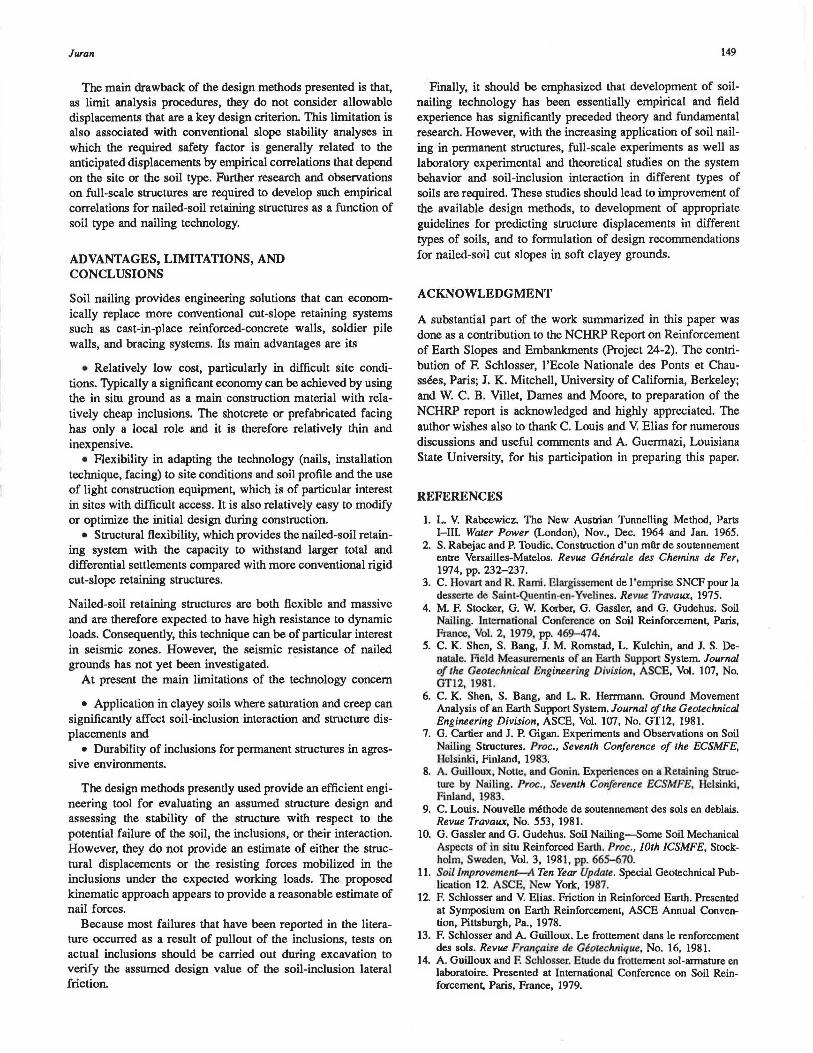
A more general solution, including the two fundamental mechanisms of soil-inclusion interaction (lateral friction and passive lateral soil reaction), has been developed by Schlosser (19). This solution involves a slices method (e.g., Bishop's modified method or Fellinius 's method) with a multicriteria analysis procedure. As shown in Figure 14, this method takes into account both the tension and the shearing capacity of the inclusions as well as the effect of their bending stiffness. When the inclusion is expected to withstand both tension (T maJ and shear (T,) forces, the available limit resisting forces in the inclusion depend on its inclination with respect to the failure surface. These limit forces are calculated according to the principle of maximum plastic work and considering Tresca's failure criterion. However, a parametric study on the effect of various design parameters (24) appears to indicate that, in the case of nailed-soil retaining structures, the bending stiffness of the inclusion has only a limited effect on the calculated safety factor (less than 6 percent). Therefore, for the practical purpose of a working stress design, a simplified stability analysis can be done assuming that the inclusions withstand only tension forces. In this analysis no consideration is given to the mo-
0
~
FAILURE CRITERIA
147
ments generated in the nails, which, as shown in Figure 13, can significantly affect the critical height at failure by excessive bending of brittle reinforcements. In the case of steel reinforce ment, local plastic bending will not generate rupture of the reinforcement, which will withstand tension and shear forces.
These design methods do not provide a solution for the maximum tension and shear forces developed under the expected working loads. They can only be used to evaluate the safety factors with respect to the shear strength characteristics of the soil and the soil-inclusion lateral friction. It is implicitly assumed that the safety factors with respect to soil cohesion (F), friction angle (F ~· and limit lateral shear stress (F1) are equal and the required safety factor has to be greater than l.5. These methods have been successfully used to predict or analyze failures in centrifugal models (6) as well as in a limited number of full-scale structures (24,25).
It should be noted that most failures that have been reported in the literature occurred as a result of pullout of the inclusions. Postfailure analyses have shown that the failure could be approximately predicted using an appropriate value of the limit shear stress mobilized at the soil-inclusion interfaces. These observations strongly suggest that pullout tests on actual inclusions should be carried out during excavation to verify the assumed design value of the soil-inclusion lateral friction.
Kinematic Limit Analysis
The second design approach (26) is based on a limit analysis that associates a kinematically admissible displacement with a failure mode as observed on model walls with a statically admissible limit equilibrium solution. The main design assumptions, shown in Figure 15, are that (a) failure occurs by a quasi-rigid body rotation of the active zone that is limited by a circular failure surface perpendicular to the uppermost inclusions; (b) at failure, the locus of maximum tension and shear forces coincides with the failure surface developed in the soil; (c) the quasi-rigid active and resistant zones are separated by a thin layer of soil at a limit state of rigid plastic flow; ( d) the shearing resistance of the soil, as defined by Coulomb's failure
FORCES IN THE BAR
I I
I
/--SLIP SUR FACE
SHEAR RESISTANCE OF THE BAR Tmai< Rn, Tc ( Re ' Rn /2
SOIL BAR FRICTION Tmaa ( ,,.D L, TL
NORMAL LATERAL EARTH THRUST ON THE BAR p ( Pma•
SHEAR RES I STANCE OF THE SO IL T < c + u Ton¢
FIGURE 14 Multlcriterla slope stability analysis method for design of nailed-soil retaining structures (19).
148
MECHANICS OF FAILURE AND DESIGN ASSUMPTIONS
TRANSPORTATION RESEARCH RECORD 1119
Tmo~= CTN . As; Tc= TN .As
'\,=SECTION AREA OF NAIL
STATE OF STRESS IN THE INCLUSION
FIGURE 15 Kinematic limit analysis approach (26).
criterion, is entirely mobilized all along the failure surface; (e) the horizontal components of the interslice forces acting on the slices shown in Figure 14 are equal; and (j) the effect of a slope (or a horizontal surcharge) at the upper surface of the nailedsoil mass on the forces in the inclusions decreases linearly along the failure surface.
The effect of the bending stiffness is analyzed considering available solutions for laterally loaded infinitely long piles. It is assumed that the maximum shear stress in the inclusion ('tc) is mobilized in the direction (a) of the sliding surface in the soil. Therefore, the ratio of Tc to T max depends only on the inclination of the inclusion with respect to the failure surface (a-~). where the actual inclination of the deformed reinforcement is calculated from the elastic solution for laterally loaded piles. A unique circular failure surface that verifies all of the equilibrium conditions of the active zone can be defined. The normal soil stress along this failure surface is calculated using Kotter's equation, and the tension and shear forces in each
FLEXIBLE INC LUSIONS
\~.~ 02 ' ~\
\ \
0.8
H = 7 2 cm Sv = ~cm
\ ' \ 1.0 '--£-...1'---- ----'---- - -'
ZIH LABORATORY MODEL
inclusion are calculated from the equilibrium of the slice comprising this inclusion. This design approach provides an estimate of the locus and values of maximum tension and shear forces mobilized in the inclusions.
Figure 16 shows a comparison between predicted and measured values of maximum tension forces in a nailed-soil model wall (22) and in a 7-m-deep experimentai waii in granuiar ground [field data obtained on this wall were reported by Plumelle (27)]. The values of maximum tension forces (T max)
are represented as a nondimensional parameter [k = Tm.J(y-H·S8 ·Sv)1 at the relative depth (z/H), where His the total structure height, Sv and S8 are, respectively, the vertical and horizontal spacings, and y is the unit weight. This comparison indicates that the proposed design approach provides a reasonable estimate of tension forces mobilized in the inclusions. However, this design method can only be used to analyze cases involving relatively simple geometry and homogeneous ground with no water flow.
FIGURE 16 Comparison of measured tension forces In a laboratory wall model (22) and a full-scale structure and theoretical predictions using the kinematic method (27).
Juran
The main drawback of the design methods presented is that, as limit analysis procedures, they do not consider allowable displacements that are a key design criterion. This limitation is also associated with conventional slope stability analyses in which the required safety factor is generally related to the anticipated displacements by empirical correlations that depend on the site or the soil type. Further research and observations on full-scale structures are required to develop such empirical correlations for nailed-soil retaining structures as a function of soil type and nailing technology.
ADVANTAGES, LIMITATIONS, AND CONCLUSIONS
Soil nailing provides engineering solutions that can economically replace more conventional cut-slope retaining systems such as cast-in-place reinforced-concrete walls, soldier pile walls, and bracing systems. Its main advantages are its
• Relatively low cost, particularly in difficult site conditions. Typically a significant economy can be achieved by using the in situ ground as a main construction material with relatively cheap inclusions. The shotcrete or prefabricated facing has only a local role and it is therefore relatively thin and inexpensive.
• Flexibility in adapting the technology (nails, installation technique, facing) to site conditions and soil profile and the use of light construction equipment, which is of particular interest in sites with difficult access. It is also relatively easy to modify or optimize the initial design during construction.
• Structural flexibility, which provides the nailed-soil retaining system with the capacity to withstand larger total and differential settlements compared with more conventional rigid cut-slope retaining structures.
Nailed-soil retaining structures are both flexible and massive and are therefore expected to have high resistance to dynamic loads. Consequently, this technique can be of particular interest in seismic zones. However, the seismic resistance of nailed grounds has not yet been investigated.
At present the main limitations of the technology concern
• Application in clayey soils where saturation and creep can significantly affect soil-inclusion interaction and structure displacements and
• Durability of inclusions for permanent structures in agressive environments.
The design methods presently used provide an efficient engineering tool for evaluating an assumed structure design and assessing the stability of the structure with respect to the potential failure of the soil, the inclusions, or their interaction. However, they do not provide an estimate of either the structural displacements or the resisting forces mobilized in the inclusions under the expected working loads. The proposed kinematic approach appears to provide a reasonable estimate of nail forces.
Because most failures that have been reported in the literature occurred as a result of pullout of the inclusions, tests on actual inclusions should be carried out during excavation to verify the assumed design value of the soil-inclusion lateral friction.
149
Finally, it should be emphasized that development of soilnailing technology has been essentially empirical and field experience has significantly preceded theory and fundamental research. However, with the increasing application of soil nailing in pennanent structures, full-scale experiments as well as laboratory experimental and theoretical studies on the system behavior and soil-inclusion interaction in different types of soils are required. These studies should lead to improvement of the available design methods, to development of appropriate guidelines for predicting structure displacements in different types of soils, and to formulation of design recommendations for nailed-soil cut slopes in soft clayey grounds.
ACKNOWLEDGMENT
A substantial part of the work summarized in this paper was done as a contribution to the NCHRP Report on Reinforcement of Earth Slopes and Embankments (Project 24-2). The contribution of F. Schlosser, l'Ecole Nationale des Ponts et Chaussees, Paris; J. K. Mitchell, University of California, Berkeley; and W. C. B. Villet, Dames and Moore, to preparation of the NCHRP report is acknowledged and highly appreciated. The author wishes also to thank C. Louis and V. Elias for numerous discussions and useful comments and A. Guermazi, Louisiana State University, for his participation in preparing this paper.
REFERENCES
1. L. V. Rabcewicz. The New Austrian Tunnelling Method, Parts I-III. Water Power (London), Nov., Dec. 1964 and Jan. 1965.
2. S. Rabejac and P. Toudic. Construction d'un mftr de soutennement entre Versailles-Matelos. RevU£ Generale des Chemins de Fer, 1974, pp. 232-237.
3. C. Hovart and R. Rami. Elargissement de l 'cmprise SNCF pour la desserte de Saint-Quenlin-en-Yvelines. Revue Travaux, 1915.
4. M. F. Stocker, G. W. Korber, G. Gassler, and G. Gudehus. Soil Nailing. Int.emalional Conference on Soil Reinforcement, Paris, France, Vol. 2, 1979, pp. 469- 474.
5. C. K. Shen, S. Bang, J. M. Romstad, L. Kulchin, and J. S. Denatale. Field Measurements of an Earth Support System. Journal of the Geotechnical Engineering Division, ASCE, Vol. 107, No. GT12, 1981 .
6. C. K. Shen, S. Bang, and L. R. Herrmann. Ground Movement Analysis of an Earth Support System. Journal of the Geotechnical Engineering Division, ASCE, Vol. 107, No. GT12, 1981.
7. G. Cartier and J.P. Gigan. Experiments and Observations on Soil Nailing Structures. Proc., Seventh Conference of the ECSMFE, Helsinki, Finland, 1983.
8. A. Guilloux, Notte, and Gonin. Experiences on a Retaining Structure by Nailing. Proc., Seventh Conference ECSMFE, Helsinki, Finland, 1983.
9. C. Loilis. Nouvelle methode de soutennement des sols en deblais. RevU£ Travaux, No. 553, 1981.
10. G. Gassler and G. Gudehus. Soil Nailing-Some Soil Mechanical Aspects of in situ Reinforced Earth. Proc., 10th JCSMFE, Stockholm, Sweden, Vol. 3, 1981, pp. 665-670.
11. Soil Improvement-A Ten Year Update. Special Geotechnical Publication 12. ASCE, New York, 1987.
12. F. Schlosser and V. Elias. Friction in Reinforced Earth. Presented at Symposium on Earth Reinforcement, ASCE Annual Convention, Pittsburgh, Pa., 1978.
13. F. Schlosser and A. Guilloux. Le frottement dans le renforcement des sols. RevU£ Fran<;aise de GeotechniqU£, No. 16, 1981.
14. A. Guilloux and F. Schlosser. Elude du frouement sol-armature en laboratoire. Presented at International Conference on Soil Reinforcement, Paris, France, 1979.
150
15. V. Elias. Friction in Reinforced Earth Utilizing Fine-Grained Backfills. Internalional. Conference on Soil Reinforcement, Paris, France, 1979, pp. 435-438.
16. F. Schlosser and I. Juran. Design Parameters for Artificially Improved Soils. Proc., Seventh ECSMFE, Brighton, England, 1979.
17. I. Juran. General Report on Speciality Techniques. Presented at Seventh Asian Regional Conference on Soil Mechanics and Foundation Engineering, Haifa, Israel, 1983.
18. A. Guilloux and F. Schlosser. Soil Nailing-Practical Applications. Presented at Symposium on Soil and Rock Improvement Techiiiques, A.I.T., Bangkok, Thailand, 198'1.
19. F. Schlosser. Analogies et differences dans le comportement et le calcul des ouvrages de soutennement 1m Terre Amiee et par clouage du sol. Annales de l' InstituJ Technique du Batiment et des Travaux Publics, No. 418, 1983.
20. I. Juran and V. Elias. Soil Nailed Structures: Analysis of Case Histories. Submitted to the ASCE Spring Convention, Atlantic City, April 1987.
21. I. Juran, P. Schlosser, M. F. Long, and G. Legeay. Full-Scale Experiment on a Reinforced Earth Bridge Abutement in Lille. Proc., Symposium on Earth Reinforcement, ASCE, Pittsburgh, Pa., 1978, pp. 556-584.
22. I. Juran, J. Beech, and E. Delaure. Experimental Study of the Behavior of Nailed Soil Retaining Structures on Reduced Scale
TRANSPORTATION RESEARCH RECORD 1119
Models. Presented at International Symposium on In-situ Soil and Rock Reinforcement, Paris, France, 1984.
23. I. Juran, S. Shafiee, and F. Schlosser. Numerical Study of Nailed Retaining Structures. Presented at 11th International Conference on Soil Mechanics and Foundation Engineering, San Francisco, Calif., 1985.
24. M. R. Pelkey. An Evaluation of Design Approaches for Soil Nailing in Excavations. Master's report. Louisiana Stat.e University, Baton Rouge, 1986.
25. F. Blondeau, M. Christiansen, A. Guilloux, and F. Schlosser. TALREN, methode de calcul des ouvrages en terre reforcee. Proc., International. Conference on In-situ Soil and Rock ReinforcemenJ, Paris, France, 1984, pp. 219-224.
26. I. Juran and I. Beech. Theoretical Analysis of Nailed Soil Retaining Structures. Presented at International Symposium on In-situ Soil and Rock Reinforcement, Paris, France, 1984.
27. C. Plumelle. Special Lecture for the French National Committee of Soil Mechanics, 1986.
Publication of this paper sponsored /Jy Committee on Transportalion Earthworks.