47
THE UNIVERSITY OF BRITISH COLUMBIA NAME 591: Computer Aided Ship Design Project Arctic Charter Yacht Concept Design Matthew Sullivan Scott Muscroft Jason Dikaitis Corey Lutes

THE UNIVERSITY OF BRITISH COLUMBIA
NAME 591: Computer Aided Ship Design Project
Arctic Charter Yacht Concept Design
Matthew Sullivan Scott Muscroft Jason Dikaitis Corey Lutes

1
EXECUTIVE SUMMARY
This project produced a concept design satisfying the requirements set forth in the NAME 591 -Computer aided ship design project course. The goal of the project was to develop a design for an icebreaking charter yacht capable of carrying 21 passengers for an extended period of time through the eastern arctic. This project was undertaken by four Masters of Engineering specializing in Naval Architecture and Marine Engineering from the University of British Columbia as part of the NAME 591 – Computer aided ship design project course. Working together with industry mentors and faculty advisors, a design was produced following the guidelines set forth by our advisors, while keeping the analyses’ level of detail consistent with industry standards regarding a concept design stage. Major emphasis was placed on maximizing the number of passengers on the ship while still having the feeling of being on a spacious and luxurious vessel. Also, the vessel was designed with easy convertibility to a traditional Caribbean touring yacht for the winter months. The final concept is a steel monohull with an overall length of 62 m, a maximum beam of 12 m, a lightship draft of 3.5 m, and a full load weight of 1700 tonnes. The vessel has a crew accommodation deck with 12 crew cabins, a B class passenger deck with 6 cabins, as well as an A class passenger deck that has 4 cabins. The vessel is powered by a diesel electric plant with two main generator sets as the yachts mission profile varies significantly. The propulsion system consists of two engines connected by geared shafts to twin screws, providing a maximum service speed of 25 knots. Overall, the project determined that a feasible vessel could be designed to meet the requirements set forth by the design project course instructors while providing a desirable passenger vessel.

2
ACKNOWLEDGEMENTS
The Arctic yacht design team would like to thanks those involved in providing invaluable help and insight
throughout the duration of this project.
Jon Mikkelsen- NAME Program Director (UBC)
Ron Holland- Project Mentor, Ron Holland Design
Dan McGreer- NAME 591 Instructor, STX Canada
Tony Vollmers- Guest Lecturer, STX Marine
Ian Saari- UBC SNAME President
Robert Allan- NAME 591 Mentor, Robert Allan Ltd

3
TABLE OF CONTENTS
Executive Summary ....................................................................................................................................................... 1
Acknowledgements ....................................................................................................................................................... 2
list of tables ................................................................................................................................................................... 6
Table of Figures ............................................................................................................................................................. 7
Vessel Overview............................................................................................................................................................. 8
Client Requirements and Mission Profile .................................................................................................................. 8
Design Requirements ................................................................................................................................................ 8
Areas of Operation (Arctic) ....................................................................................................................................... 9
Applicable Rules and Regulations ............................................................................................................................. 9
Class Rules ............................................................................................................................................................. 9
Flag State ............................................................................................................................................................ 10
Environmental Regulations ................................................................................................................................. 10
Areas Volumes and Weights ........................................................................................................................................ 11
Areas and Volumes .................................................................................................................................................. 11
Crew Accommodations ....................................................................................................................................... 11
Passenger Accommodations ............................................................................................................................... 11
Ship Services ....................................................................................................................................................... 12
Technical Facilities and Miscellaneous Storage .................................................................................................. 13
Weights ................................................................................................................................................................... 15
Hull Description ........................................................................................................................................................... 16
Rudder Sizing ............................................................................................................................................................... 17
Preliminary Rudder Design ...................................................................................................................................... 17
Straight line Stability ............................................................................................................................................... 17
Hull Calculations ................................................................................................................................................. 17
Rudder Calculations ............................................................................................................................................ 18

4
Resistance .................................................................................................................................................................... 20
Bare Hull Resistance ................................................................................................................................................ 20
Appendage Drag ...................................................................................................................................................... 21
Propulsion and Powering ............................................................................................................................................. 22
Mission Profile ......................................................................................................................................................... 22
System Structure ..................................................................................................................................................... 22
System Type ........................................................................................................................................................ 22
Propulsion System .............................................................................................................................................. 23
Emissions and Fuel Costs ......................................................................................................................................... 23
Fuel Cost Estimate .............................................................................................................................................. 23
Emission Estimate ............................................................................................................................................... 24
Structural ..................................................................................................................................................................... 25
Longitudinal Strength .............................................................................................................................................. 25
Bending Strength and Stiffness ............................................................................................................................... 25
Transverse Bulkheads .............................................................................................................................................. 26
Bottom Structures ................................................................................................................................................... 26
Side Structures ........................................................................................................................................................ 27
Helicopter Landing Area Plating .............................................................................................................................. 28
Hull Cross Section .................................................................................................................................................... 29
General Arrangement .................................................................................................................................................. 31
Crew Deck ............................................................................................................................................................... 31
Accommodation .................................................................................................................................................. 31
Living Spaces ....................................................................................................................................................... 31
Service Spaces ..................................................................................................................................................... 32
Diving Area & Sauna ........................................................................................................................................... 32
Side Launch ......................................................................................................................................................... 32
Garbage Storage ................................................................................................................................................. 32

5
B Class Deck ............................................................................................................................................................. 33
B Class Accommodation ...................................................................................................................................... 33
Dining Area ......................................................................................................................................................... 33
Main Atrium – Bottom Floor ............................................................................................................................... 33
Guest Office ........................................................................................................................................................ 34
Meeting Room .................................................................................................................................................... 34
Salon & Spa ......................................................................................................................................................... 34
A Class Deck ............................................................................................................................................................. 34
A Class Accommodation...................................................................................................................................... 34
Workout Facility .................................................................................................................................................. 35
Main Atrium – Top Floor ..................................................................................................................................... 35
Bridge Deck ............................................................................................................................................................. 35
Captain/First Mate Quarters ............................................................................................................................... 35
Helipad and Hanger ............................................................................................................................................ 35
Sun Deck .................................................................................................................................................................. 36
Machinery Room & Watertight Bulkheads .................................................................................................................. 37
Fresh Water Production .......................................................................................................................................... 37
Waste Water Treatment ......................................................................................................................................... 37
tank arrangement ........................................................................................................................................................ 38
Stability ........................................................................................................................................................................ 39
Intact Stability ......................................................................................................................................................... 39
Damage Stability ..................................................................................................................................................... 40
Seakeeping .............................................................................................................................................................. 41
Economic Analysis ....................................................................................................................................................... 43
Revenue Estimation ................................................................................................................................................ 43
Operating cost estimation ....................................................................................................................................... 43
Construction Cost Estimates ................................................................................................................................... 44

6
Payback Period estimation ...................................................................................................................................... 44
Conclusion and Recommendations ............................................................................................................................. 45
Works Cited ................................................................................................................................................................. 46
LIST OF TABLES
Table 1: Operational Requirements ............................................................................................................................. 9
Table 2: Crew Facilities areas and volumes ................................................................................................................. 11
Table 3: Passenger accommodations .......................................................................................................................... 12
Table 4: Passenger common spaces ............................................................................................................................ 12
Table 5: Passenger area and volume ........................................................................................................................... 12
Table 6: Catering Service ............................................................................................................................................. 13
Table 7: Navigation, administration and medical areas .............................................................................................. 13
Table 8: Hotel Services................................................................................................................................................. 13
Table 9: Service facilities area and volume .................................................................................................................. 13
Table 10: Technical areas and volumes ....................................................................................................................... 14
Table 11: Liquid hold volume estimates ...................................................................................................................... 14
Table 12: Activity related storage ................................................................................................................................ 14
Table 13: Equipment storage ....................................................................................................................................... 15
Table 14: Lightweight ship estimate ............................................................................................................................ 15
Table 15: Additional weight for deadweight condition ............................................................................................... 15
Table 16: Vessel particulars ......................................................................................................................................... 16
Table 17: Span, chord, and aspect ratio of the rudders .............................................................................................. 17
Table 18: Non-dimensionalized forms of bare hull hydrodynamic derivatives ........................................................... 18
Table 19: Non-dimensionalized forms of rudder hydrodynamic derivatives .............................................................. 19
Table 20: Span, chord, and aspect ratio of the skegs .................................................................................................. 19

7
Table 21: Non-dimensionalized forms of skeg hydrodynamic derivatives .................................................................. 19
Table 22: Non-dimensionalized forms of the sums of the hydrodynamic derivatives and stability parameter C....... 19
Table 23: Appendage Drag .......................................................................................................................................... 21
Table 24: Operating Profile .......................................................................................................................................... 22
Table 25: Fuel cost summary ....................................................................................................................................... 24
Table 26: Fuel emissions summary .............................................................................................................................. 24
Table 27: Bottom plating thicknesses of various structural members ........................................................................ 27
Table 28: Side plating thicknesses of various structural members.............................................................................. 28
Table 29: Intact Stability Results .................................................................................................................................. 39
Table 21: Revenue Estimation summary ..................................................................................................................... 43
Table 22: Operating cost estimation ........................................................................................................................... 44
Table 23: Group weight breakdown ............................................................................................................................ 44
Table 24: Bid price summary ....................................................................................................................................... 44
TABLE OF FIGURES
Figure 1: Transport Canada Arctic Safety Control Zones ............................................................................................... 9
Figure 2: Initial hull design ........................................................................................................................................... 16
Figure 3: Bare Hull and Appendage drag Resistance ................................................................................................... 20
Figure 4: SFC curve for CAT 3512B genset ................................................................................................................... 23
Figure 5: SFC for CAT C32 ACERT genset ..................................................................................................................... 24
Figure 6: Transverse cross section of the hull ............................................................................................................. 30
Figure 7: Stability Curves for Various Loading Cases ................................................................................................... 40
Figure 8: Floodable Lengths ......................................................................................................................................... 40
Figure 9: Operability plot at 15 knts ............................................................................................................................ 41
Figure 10: RAO Simulation Results .............................................................................................................................. 42

8
VESSEL OVERVIEW
This section will deal with the perceived client motivation as well as owner requirements. This was the preliminary
portion of the project and was done to set out the design requirements and constraints of the vessel. The mission
profile, areas of operation, environmental requirements and applicable class and flag state regulations are also
detailed in this section.
CLIENT REQUIREMENTS AND MISSION PROFILE
The client that this vessel was designed for was a hypothetical charter company that would be operating an Arctic
charter business. The imagined customer base is wealthy outdoor enthusiasts and adventurists looking for a one
of a kind Arctic adventure. The main design motivation for this project was to create an environmentally
sustainable boat that would be able to navigate the lower to mid Arctic during the winter months. The
atmosphere aboard was to be a small intimate atmosphere with ample visibility to the outdoors. This was
balanced with the need to have all the comforts of home while aboard the vessel.
In addition to this, the yacht must have the capabilities to provide equipment to allow customers to easily embark
and disembark the vessel for day trips, fishing and other outdoor activities. The yacht will also have the capability
of providing helicopter tours and heli-skiing services via an on board helicopter.
The mission profile of this boat is to pick up passengers from a predetermined port and transport them to the
lower Arctic from where they will tour a pre-designated route that features many of the natural beauties of an
Arctic ecosystem. In addition, the boat must be economically viable so as to have a reasonable payback period
and money making potential. To increase the operating window for this boat, it was determined that operating in
a tropical region during winter months would be economically beneficial to the operating party.
DESIGN REQUIREMENTS
From the customer requirements, the design teamed came up with the design requirements for the vessel so as to
fit the customer requirements. The design requirements were determined by researching typical yachts of similar
function and passenger boat regulations to determine the amount of passengers, cruising speed and crew
requirements. It was determined that an optimal number of passengers is 20-21 placed in a two class system (First
and Second Class). Each class would be paying an appropriate sum of money and would be provided with
appropriate services, accommodations and amenities. In addition to this the vessel with have the operational
requirements documented in Table 1. The passenger number was determined so as to fall within a certain
regulation bracket within the IMO SOLAS regulations (International Convention for the Safety of Life at Sea, 2004).
In addition to the Arctic operating requirements, the boat must be designed in such a way that it can be used in
tropical areas during the winter months. As such it must contain the required amenities that allow for passenger
comfort such as an air conditioning system.

9
Operational Parameter Value
Cruise Speed 25 knots Ice Class DNV Ice class 1C or equivalent Passengers 21 Crew ~20 LOA, Beam, Draft (lightship) 62m, 12m , 3.5m Range 6000 Nautical miles
Table 1: Operational Requirements
AREAS OF OPERATION (ARCTIC)
With the hull class designation of DNV Ice Class 1C, the vessel will be permitted to operate in areas 7-16 of the
Arctic Safety Control Zones as regulated by Transport Canada. An approximate layout of these areas is shown in
Figure 1.
Figure 1: Transport Canada Arctic Safety Control Zones
APPLICABLE RULES AND REGULATIONS
This section will outline the various regulations and regulatory bodies that will be followed and consulted
throughout the design process.
CLASS RULES
This vessel will be designed according to Lloyd’s Register Rules and Regulations for the Classification of Ships. The
ship will be designated as an Ice Class passenger ship.

10
FLAG STATE
The ship will be registered in Canada as that is where its primary area of operation will be and as such, it must
comply with all applicable regulations set out.
ENVIRONMENTAL REGULATIONS
The boat will adhere to all Transport Canada environmental regulation for shipping operations in the Arctic. The
propulsion system will be designed such that it meets and exceeds IMO Tier III requirements.

11
AREAS VOLUMES AND WEIGHTS
This section will document the procedure and results of how the volume, areas and preliminary weight calculations
of the ship. The values from here will then be used to determine the hull size and shape.
AREAS AND VOLUMES
The following subsections detail the determination of areas and volumes on the boat. One of the primary design
considerations of this boat was to create 2 separate environments within the ship; one for the crew and one for
the passengers. This was done so as to keep the two groups separate from each other and as such much of the
amenities on the boat had to be duplicated.
CREW ACCOMMODATIONS
To determine the required area for crew accommodations, the required area as dictated by legislation was used.
This value is specified is a meagre 2m2 per crew, and this value was increased to 7.5 m2 as to increase the comfort
of crew. The general layout for was assumed to be 3m by 5m identical cabins with two beds per cabin. For a crew
of 21 this resulted in 12 cabins, 3 of which with one bed which were reserved for the captain, first mate and chief
engineer. A 25% margin was included to account for walls and doors and other such structures.
In addition, a crew mess measuring 5m by 6m were included and a lounge with the same dimensions as the mess.
Table 2 summarizes the crew facilities for the vessel, for the volume calculation it assumed a constant ceiling
height of 3m.
Crew # of Cabins
Beds per Cabin
Area m^2
Height m Volume m^3
Rooms 12 21 180 3 540
Crew Lounge 21 1.42857143 30 3 90
Crew Mess 21 1.42857143 30 3 90
Main Stairs 20.25 9 182.25
Cabin Corridors, wall lining (25% of cabin area) 45 3 135
Total 302.25 1037.25
Table 2: Crew Facilities areas and volumes
PASSENGER ACCOMMODATIONS
To determine the passenger accommodation areas and volumes a similar method to the crew facilities was
applied. The A class passenger cabins were assumed to approximately 35 m2 and the B class passenger cabins
were assumed to be 72 m2 in size. As with the crew accommodation, a 25% margin was applied. The final
calculations for passenger rooms are located in Table 3.

12
Passenger Class # of Cabins
Outdoor Space
Area m^2
Height m
Volume m^3
A 6 210 3 630
B 4 288 3 864
Cabin Corridors, wall lining (25% of cabin area) 124.5 3 373.5
Total 622.5 1867.5
Passenger common spaces were the next area of consideration when it came to areas and volumes. The details of
the assumed values are located in Table 4.
Name / Use of Space Area m^2
Height m
Volume m^3
Lounge 132 3 396 Office/Meeting Room 15 3 45 Spa 25 3 75 Restaurant 101 3 303 Sauna/ Lower Deck Spa 15 3 45 Lower Deck Outdoor Area 195 3 585 Spa (Upper Deck) 20 3 60 Total 478 1434
Table 4: Passenger common spaces
A summary of all area and space accommodations is located in Table 5. It should be noted that for all volume
calculations a mean ceiling height of 3m was used.
Area Unit Volume Unit
1100.5 m2 3301.5 m3
Table 5: Passenger area and volume
SHIP SERVICES
Ship service includes everything that is involved in running the ship this includes hotel and catering as well as
navigation and control. Technical areas such as the engine room are covered in a separate section.
The space requirements covered under this section are everything that have to do with ensuring passenger
comfort. This includes laundry, cleaning and food services and it is assumed that the crew equivalent services will
be met with the same areas. The areas and volume for components of the service facilities are located in tables 5
and 6 with a summary of volume and area in Table 7.
Table 3: Passenger accommodations

13
Name / Use of Space Area m^2
Height m
Volume m^3
Galleys 22 3 66
Provision Store 33 3 99
Garbage 11 3 33
Total 44.5 198
Table 6: Catering Service
Name / Use of Space Area m^2
Height m
Volume m^3
Navagation and Radio 220 3 660
Offices 22 3 66
Sick Bay 22 3 66
Total 264 792
Table 7: Navigation, administration and medical areas
Name / Use of stairs Area m^2
Height m
Volume m^3
Laundry and Linen Store 22 3 66
Hotel Store 22 3 66
Total 20 132
Table 8: Hotel Services
Area Unit Volume Unit
374 m2 1122 m3
Table 9: Service facilities area and volume
TECHNICAL FACILITIES AND MISCELLANEOUS STORAGE
This section will cover the volume and area calculations for the technical areas (engine room,etc.) and the
miscellaneous storage for such things as boats and sporting equipment.
The technical areas consist of all the mechanical and working components of the boat. Included in the engine and
pump room is the exhaust and air intake systems as well as thrusters and stabilizers. The area estimation was
done on an average of m3/kW. As the engine could not be specified at this point in the design, a value of similar
yachts of the same role was chosen. This includes the generator specifications as well. The area of the engine
room was derived from using an average of a 6m ceiling height (approximately 2 decks high). These calculations
are summarized in Table 10.
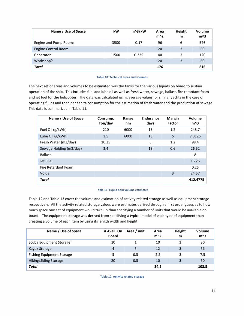
14
Name / Use of Space kW m^3/kW Area m^2
Height m
Volume m^3
Engine and Pump Rooms 3500 0.17 96 6 576
Engine Control Room 20 3 60
Generator 1500 0.325 40 3 120
Workshop? 20 3 60
Total 176 816
Table 10: Technical areas and volumes
The next set of areas and volumes to be estimated was the tanks for the various liquids on board to sustain
operation of the ship. This includes fuel and lube oil as well as fresh water, sewage, ballast, fire retardant foam
and jet fuel for the helicopter. The data was calculated using average values for similar yachts in the case of
operating fluids and then per capita consumption for the estimation of fresh water and the production of sewage.
This data is summarized in Table 11.
Name / Use of Space Consump. Ton/day
Range nm
Endurance days
Margin Factor
Volume m^3
Fuel Oil (g/kWh) 210 6000 13 1.2 245.7
Lube Oil (g/kWh) 1.5 6000 13 5 7.3125
Fresh Water (m3/day) 10.25 8 1.2 98.4
Sewage Holding (m3/day) 3.4 13 0.6 26.52
Ballast 8
Jet Fuel 1.725
Fire Retardant Foam 0.25
Voids 3 24.57
Total 412.4775
Table 11: Liquid hold volume estimates
Table 12 and Table 13 cover the volume and estimation of activity related storage as well as equipment storage
respectively. All the activity related storage values were estimates derived through a first order guess as to how
much space one set of equipment would take up than specifying a number of units that would be available on
board. The equipment storage was derived from specifying a typical model of each type of equipment than
creating a volume of each item by using its length width and height.
Name / Use of Space # Avail. On Board
Area / unit Area m^2
Height m
Volume m^3
Scuba Equipment Storage 10 1 10 3 30
Kayak Storage 4 3 12 3 36
Fishing Equipment Storage 5 0.5 2.5 3 7.5
Hiking/Skiing Storage 20 0.5 10 3 30
Total 34.5 103.5
Table 12: Activity related storage

15
Name / Use of Space # Avail. On Board
Area/unit Area m^2
Height m
Volume m^3
Helicopter 1 191.5 3.5 670.25
Fishing Skiff 1 8.91 8.91 3 26.73
RIBS 2 7 14 2 28
Total 15.91 214.41 724.98
Table 13: Equipment storage
WEIGHTS
The following section documents the first order approximation of lightweight condition as well as the deadweight
condition of the ship. The lightweight condition is comprised of the ship without any fluids or pieces of equipment
on board. The deadweight condition consists of the operating condition of the ship with all cargo aboard with all
fluid tanks full. The method used in this section was to assume an average weight of volume per component than
multiplying the estimated volume by that average (Dan McGreer, 2014). The lightweight ship condition is
estimated and documented in Table 14.
Weight Group Unit Value Coeff ton/unit Weight (ton)
Hull Structure Hull Vol 4084.208 0.11 449.262825
Superstructure Dh Vol 3436.5 0.06 206.19
Interior Outfitting Area 1779.75 0.15 266.9625
Machinery Pp + Pa (kW)
5000 0.06 300
Ship Outfitting Volume 7520.708 0.005 37.6035375
Total Hull Volume Volume 7520.708 0.121 910.005608
Reserve % 5.00% 45.5002804
Lightweight 1305.51914
Table 14: Lightweight ship estimate
Item Unit Value Coeff ton/unit Weight ton
Equipment Storage Capacity 5.233 1 5.233
Activity Related Storage Capacity 1.818 1 1.818
Crew Persons 22 0.1 2.2
Passengers Persons 20 0.1 2
Provision and Stores Persons 42 0.0135 0.567
Fuel Oil Consumption 245.7 1 245.7
Lube Oil Consumption 7.3125 1 7.3125
Fresh Water Consumption 98.40 1 98.4
Sewage in Holding Tanks Produced 26.52 1 26.52
Deadweight 389.7505
Table 15: Additional weight for deadweight condition

16
HULL DESCRIPTION
The hull form chosen was directly related to the NPL series. This series was chosen for a variety of factors. Firstly,
the large swept bow and smooth hull lines provide for an attractive hull design. Secondly, the raked how and
shallow entrance angle provide for improved icebreaking performance in brash ice conditions as the hull simply
deflects ice chunks off to the side as it moves through the ice. In addition to this, the hull design in a semi planning
and thus is efficient at higher transit speeds which may need to be undertaken for short periods of time. The
absence of sharp chines and lines also provides for improved performance at slower speeds.
The decision to choose this hull form was also based on the fact that many of the target hull form parameters were
met by this hull series. For initial shape generation, a set of offsets was used to create splines within Siemens NX,
from here; these were turned into successive sheets which were then joined to create the initial hull design. A
screen shot of the initial hull shape is located in Figure 2.
Figure 2: Initial hull design
Table 16 shows a list of target hull parameters. These were determined from the initial volume area and weight
calculations and the chosen hull form and design speed.
Length PP 61.57 Froude No. 0.314
Breadth WL 11.2 L/Δ1/3 5.534
Draught 3.7 L/B 5.5
L/D 16.5 B/T 3
Displacement 1377.505 Cb 0.535
Cp 0.58
Table 16: Vessel particulars

17
RUDDER SIZING
PRELIMINARY RUDDER DESIGN
Using the Det Norkse Veritas equation, a preliminary estimate of the area of the rudder may be calculated:
𝑆 ≈𝑇 ∙ 𝐿𝑝𝑝
100[1.0 + 25.0 ∙ (
𝐵
𝐿𝑝𝑝
)
2
]
Where
T = Draft
Lpp= Length Between Perpendiculars
B = Breadth
𝑆 ≈3.9𝑚 ∙ 65𝑚
100[1.0 + 25.0 ∙ (
11.8𝑚
65𝑚)
2
]
𝑆 ≈ 4.624 𝑚2
Using this preliminary estimate, an aspect ratio can be estimated using a varying range of spans and chords of the
rudder. Due to the fact that this is an icebreaking vessel and pieces of ice will be travelling under the keel of the
vessel, we would like to minimize the size of the span of the rudder in order to reduce potential vibrations and
damage to the rudder and or rudder stock while still maintaining enough depth to minimize the drag force.
Dimensions of Rudders
Span (m) Chord (m) AR 2AR
2.6 1.78 1.46 2.92
Table 17: Span, chord, and aspect ratio of the rudders
Because the rudder is flush against the hull, the control surface will behave as if the span was doubled, therefore
for all further calculations, the aspect ratio we will be using is the 2AR value above.
STRAIGHT LINE STABILITY
A vessel possesses straight line stability if the following parameter, C has a positive value:
𝐶 = 𝑌𝑣′𝑁𝑟
′ − 𝑁𝑣′(𝑌𝑟
′ − 𝑚′)
HULL CALCULATIONS
By using semi-empirical curve fit formulas based on a ship’s length, beam and draught, the following hydrodynamic
derivatives were obtained for the hull:

18
Bare Hull Semi-empirical curve fits
Y'v -0.01753
N'v -0.00728
Y'r 0.00387
N'r -0.00301
m' 0.01168
C -4.02668E-06*
Table 18: Non-dimensionalized forms of bare hull hydrodynamic derivatives
*It may be noted that the bare hull is not initially straight line stable
RUDDER CALCULATIONS
For the rudder, the following Whicker & Fehlner equation for low AR lift may be used to calculate the coefficient of
lift:
𝐶𝐿𝛼 =1.8𝜋𝐴𝑅
1.8 + 𝑐𝑜𝑠𝛺√4 +𝐴𝑅2
𝑐𝑜𝑠4𝛺
where,
AR = Aspect Ratio = 2.92
Ω = quarter chord sweep angle, assumed to be 0
𝐶𝐿𝛼 =1.8𝜋𝐴𝑅
1.8 + √4 + 𝐴𝑅2
𝐶𝐿𝛼 = 3.095
By using the following equation, the first non-dimensional hydrodynamic derivative is calculated:
𝑌𝑟′𝑣 =−𝐶𝐿𝛼𝑆
𝐿2
Using similar equations, the remainder of the rudder hydrodynamic derivatives are calculated and presented in the
following table:

19
Rudder Derivatives
Yr'v -0.00338
Nr'v 0.00123
Yr'r 0.00123
Nr'r -0.00045
Table 19: Non-dimensionalized forms of rudder hydrodynamic derivatives
Skeg Calculations
By treating the skegs as rudders, similar calculations could be performed for the span, chord, and aspect ratio of
the skegs:
Dimensions of Skegs
Span (avg) Chord AR 2AR
1 8 0.125 0.25
Table 20: Span, chord, and aspect ratio of the skegs
Again, by similar calculations, the hydrodynamic derivatives of the skegs may be calculated and are presented in
the following table:
Skeg Derivatives
Ys'v -0.00070
Ns'v 0.00018
Ys'r 0.00018
Ns'r -0.00004
Table 21: Non-dimensionalized forms of skeg hydrodynamic derivatives
By summing the hydrodynamic derivatives of the hull, rudders, and skegs, the overall stability parameter may be
calculated:
Sum of Derivatives
Y'v -0.02162
N'v -0.00587
Y'r 0.00528
N'r -0.00350
C 3.82977E-05
Table 22: Non-dimensionalized forms of the sums of the hydrodynamic derivatives and stability parameter C
With the addition of the rudders and skegs, the ship is now straight line stable as the stability parameter, C, is now
positive.

20
RESISTANCE
This section covers that calculation of both the bare hull effective horsepower as well as the EHP with the inclusion
of appendage drag.
BARE HULL RESISTANCE
As the hull is derived from the NPL hull series, the resistance formulation was relatively straight forward. Initially,
it was planned to use Paramarine for all the resistance calculations but due to the design hull speed being slightly
outside the parameters of the NPL series regression within the software package would only return error messages
and would not compute the resistance. The next method was to simply use CR values from published values
(Molland, 2011). Figure 3 shows EHP curves for both the bare hull and with appendages. The orange curve is the
appendage drag curve while the blue curve is the bare hull drag.
Figure 3: Bare Hull and Appendage drag Resistance
y = 24.369e0.2553x
y = 30.257e0.2484x
0
1000
2000
3000
4000
5000
6000
7000
0 5 10 15 20 25
EHP
(kW
)
Speed (knots)
Bare Hull EHP vs. Speed
Hull with appendages
Expon. (Bare Hull EHP vs. Speed)
Expon. (Hull with appendages)

21
APPENDAGE DRAG
Appendage drag was considered for the following items: rudder, bow thruster and skegs. Drag correlations
documented in Ship Resistance and Propulsion were used to find a drag estimate for each item. These were
resistances were summed up and added to the bare hull resistance to obtain an overall resistance for the hull
(Molland, 2011). Table 23 shows the percentage of appendage of overall drag as a function of speed.
V (knots) Bare Hull Appendage Drag %BH
11.51548801 70.30997183 10.78928832 15.34532
12 88.2453093 12.59850069 14.37658
12.95492401 97.34539065 13.51646389 13.88506
14.39436001 132.1443692 16.53795149 12.51506
15 149.3829345 17.89670882 11.98042
15.83379601 175.4814305 19.85173678 11.31273
17.27323201 231.8151157 23.45603519 10.11842
18 271.0861225 25.38569258 9.364438
18.71266801 313.4898529 27.3492478 8.724125
20.15210401 432.5061344 31.52992856 7.290053
21.59154001 610.9974599 35.99675935 5.891474
Table 23: Appendage Drag

22
PROPULSION AND POWERING
The section documents the method and rationales used to design and spec the propulsion system used for this
boat. This includes the mission profile, primary gensets, propeller selection and propulsion type.
MISSION PROFILE
The mission profile was derived from considering three different operating modes: Arctic operation, transit and
Tropical operation. The percentage of operating time per mode was determined using a weighted average of
mode length (i.e months of operation per mode) and a specific breakdown of operating profiles within each mode
(i.e. time spent in port, at anchor and steaming). The final operating profile is located in table 18 and is based on
365 days per year of operation.
The deck service load was considered by examining the operation of the crane that we will be used. A preliminary
size estimate for the crane yielded a load of 40 kW. The hotel service was estimated by examining yacht of similar
size and function and it was determined that 625 kW was an appropriate load.
SYSTEM STRUCTURE
This section will cover the proposed structure of the propulsion system for the arctic yacht. The prime mover type
as well as the main propulsor selection will be discussed.
SYSTEM TYPE
It was determined that a diesel-electric generator system will be used in this ship. The rationale for this was based
on its applicability to a variable operating profile. IEP are particularly useful because they allow the primary
generators to be cycled on and off to allow for the most efficient use of each generator.
For this concept design it was decided that 2 primary diesel generators would be used in conjunction with a
smaller high efficiency auxiliary diesel generators. The models chosen were two CAT 3512B gensets for the
primary generators and a CAT ACERT C32 generator for the smaller auxiliary generator. The total installed
generating capacity for this power plant was 3930 kW.
Mode Units Port Normal Transit (15 knts)
Coastal Transit (12 knts)
Slow Transit
Maneuv. Ice Breaking
% time 28% 21% 28% 12% 6% 12%
annual hours h 2435.28 1848.36 2461.56 1086.24 556.26 1086.24
propulsion load
% 0% 0% 0% 0% 0%
propulsion load
ekW 0.00 2087.00 1043.60 181.11 181.11 1940.66
thrusters ekW 0.00 0.00 0.00 0.00 485.00 0.00
Deck Load ekW 40.00 0.00 0.00 0.00 0.00 0.00
Ship Service ekW 625.0 625.00 625.00 625.00 625.00 625.00
Table 24: Operating Profile

23
The main electrical system and electric motors were specified using an ABB booklet supplied by Dan McGreer at
STX.
PROPULSION SYSTEM
A fixed pitch, twin screw system was selected as the drive system for this boat. This is due mainly to redundancy
which is a favourable characteristic for operation as help is a long way off and getting stranded in ice flows carries
quite a substantial risk. The choice to go with a straight shaft system was made for cost reduction purposes and
the unavailability of of azipods or z-drives in the required power range.
EMISSIONS AND FUEL COSTS
A vital component of this design process was to make the ship an economical business venture. Thus a fuel cost
estimate was a must. In addition to this, an emission estimate must be performed to ensure that the boat will
meet emission requirements and if not, what sort of exhaust treatment must be performed. The estimates will be
provided yet a detailed design of the exhaust treatment is outside of the scope of the initial design spiral for this
vessel.
FUEL COST ESTIMATE
Using the specific fuel consumption at various power loads for the generator sets, a regression was performed so
as to interpolate sfc value. These were used to determine a fuel consumption rate as well as the optimal load
condition for each generator. The SFC for both generator types are located in Figure 4 and Figure 5.
Figure 4: SFC curve for CAT 3512B genset

24
Figure 5: SFC for CAT C32 ACERT genset
The optimal operation point for these generators was determined by observing the lowest point on the regression
curve. For the CAT 3512B, this was at approximately 85-90 percent load and the ACERT C32 it occurred at a load of
100%. Using this information and the mission profile the optimal fuel cost was determined. Table 25 summarizes
the fuel costs for all operating modes, generators and provides a summary of the overall costs.
total fuel/yr t/y 337.16 1091.04 931.96 178.02 251.69 608.01
annual fuel cost
$ 345,593.14 1,118,317.03 955,261.88 182,475.51 257,982.16 623,207.80
total fuel cost
$ 3,482,837.51
Table 25: Fuel cost summary
EMISSION ESTIMATE
The emission estimates were performed by using correlations that relate the specific type of emission to the
specific fuel consumption. The emissions examined are CO2 and sulphur and the findings are summarized in Table
27.
CAT 3512C (1) Units Port 12 knts 15 knts Slow Transit
Maneuv. Ice Breaking
Total Sulphur/yr Tonne 0.10
0.26
0.28
0.02
0.02
0.08
Total CO2/yr Tonne 162.49
418.74
452.92
39.14
27.67
137.76
Table 26: Fuel emissions summary
The total CO2 emission for the year is 1238.71 tonnes and the sulphur emission per year is 0.76 tonnes per year.
From the resistance predictions and the inclusion of a hotel load and deck service load the appropriate generator
sets were selected. From the analysis of the emissions, it is evident that for tier III standards to be met, exhaust
treatment must be undertaken.

25
STRUCTURAL
LONGITUDINAL STRENGTH
Vertical Bending Moments – Stillwater conditions
The design stillwater bending moments within 0.4 L amidships are normally not to be taken less than:
𝑀𝑆𝑂 = 0.0052𝐿3 𝐵 (𝐶𝐵 + 0.7) (𝑘𝑁𝑚)
𝑀𝑆𝑂 = 0.0052 ∙ 61.573 ∙ 11.2(. 535 + 0.7) (𝑘𝑁𝑚)
𝑀𝑆𝑂 = 16787.9 𝑘𝑁𝑚
Outside 0.4 L amidships MSO may be gradually decreased for zero at F.P. and A.P.
Wave load conditions
𝑀𝑊𝑂 = 0.11 𝐶𝑊 𝐿2 𝐵 (𝐶𝐵 + 0.7)(𝑘𝑁𝑚) 𝑖𝑛 𝑠𝑎𝑔𝑔𝑖𝑛𝑔
= 0.19 𝐶𝑊 𝐿2 𝐵 (𝐶𝐵)(𝑘𝑁𝑚) 𝑖𝑛 ℎ𝑜𝑔𝑔𝑖𝑛𝑔
where,
𝐶𝑊 = wave coefficient = 0.0792L
𝑀𝑊𝑂 = 0.11 ∙ 0.0792 ∙ 61.573 ∙ 11.2 (. 535 + 0.7) (𝑘𝑁𝑚) 𝑖𝑛 𝑠𝑎𝑔𝑔𝑖𝑛𝑔
𝑀𝑊𝑂 = 28126.15 𝑘𝑁𝑚 𝑖𝑛 𝑠𝑎𝑔𝑔𝑖𝑛𝑔
𝑀𝑊𝑂 = 0.19 ∙ 0.0792 ∙ 61.573 ∙ 11.2 ∙ .535 (𝑘𝑁𝑚) 𝑖𝑛 ℎ𝑜𝑔𝑔𝑖𝑛𝑔
𝑀𝑊𝑂 = 21045.4 𝑘𝑁𝑚 𝑖𝑛 ℎ𝑜𝑔𝑔𝑖𝑛𝑔
BENDING STRENGTH AND STIFFNESS
Section Modulus – Longitudinal Axis
The section modulus requirements within 0.4 L amidships about the transverse neutral axis based on cargo and
ballast conditions are given by:
𝑍 =𝑀𝑆 + 𝑀𝑊
175103 (𝑐𝑚3)
𝑍 =16787.9 + 28126.15
175103 (𝑐𝑚3)
𝑍 = 256651.7 𝑐𝑚3
Section Modulus – Transverse Neutral Axis

26
The midship section modulus about the transverse neutral axis is not to be less than:
𝑍𝑂 = 𝐶𝑊𝑂 𝐿2 𝐵 (𝐶𝐵 + 0.7) (𝑐𝑚3)
where,
𝐶𝑊𝑂 = 5.7 + 0.022L
𝑍𝑂 = (5.7 + 0.022𝐿) 𝐿2 𝐵 (𝐶𝐵 + 0.7) (𝑐𝑚3)
𝑍𝑂 = (5.7 + 0.022 ∙ 61.57) 61.572 ∙ 11.2 (.535 + 0.7) (𝑐𝑚3)
𝑍𝑂 = 369906.5 𝑐𝑚3
TRANSVERSE BULKHEADS
According to DNV Rules for Classification of Ships as well as Lloyd’s Registry Rules and Regulations, a ship must
have four transverse watertight bulkheads. The collision bulkhead is found near the bow of the ship and its
approximate location may be determined by the following equations:
𝑥𝑐 (𝑚𝑖𝑛𝑖𝑚𝑢𝑚) = 0.05𝐿𝐹 − 𝑥𝑟
𝑥𝑐 (𝑚𝑎𝑥𝑖𝑚𝑢𝑚) = 0.05𝐿𝐹 + 3 − 𝑥𝑟
where,
𝐿𝐹 = Length of waterline
𝑥𝑟 = 0 for ships with ordinary bow shape
𝑥𝑐(𝑚𝑖𝑛𝑖𝑚𝑢𝑚) = 0.05 ∙ 62𝑚 = 3.1𝑚
𝑥𝑐(𝑚𝑎𝑥𝑖𝑚𝑢𝑚) = 0.05 ∙ 62𝑚 + 3 = 6.1𝑚
Two additional transverse bulkheads must be placed on either side of the machinery room, and the afterpeak
bulkhead is located aft of the machinery room. In terms of height of the watertight bulkheads, they are in general
to extend from the keel of the ship to the freeboard deck.
BOTTOM STRUCTURES
Because our ship is a passenger vessel, a double bottom must be fitted extending from the collision bulkhead to
the afterpeak bulkhead. The height of the inner bottom must be sufficient to give good access to all parts of the
double bottom.
According to DNV Rules for Classification of Ships, the minimum bottom plating thicknesses of various structural
sections of the hull can be determined from the following equations:
Keel Plate and garboard strake:
𝑡 = 7 + 0.05 ∙ 𝐿 + 𝑡𝑘 (𝑚𝑚)

27
Bottom and bilge plating:
𝑡 = 5 + 0.04 ∙ 𝐿 + 𝑡𝑘 (𝑚𝑚)
Inner bottom plating:
𝑡 = 5 + 0.03 ∙ 𝐿 + 𝑡𝑘 (𝑚𝑚)
Floors and longitudinal girders – center:
𝑡 = 6 + 0.04 ∙ 𝐿 + 𝑡𝑘 (𝑚𝑚)
Floors and longitudinal girders – other:
𝑡 = 6 + 0.02 ∙ 𝐿 + 𝑡𝑘 (𝑚𝑚)
Transverse Frames:
𝑡 = 4.5 + 0.015 ∙ 𝐿 + 𝑡𝑘 (𝑚𝑚)
Bottom longitudinals:
𝑡 = 4.5 + 0.015 ∙ 𝐿 + 𝑡𝑘 (𝑚𝑚)
where,
L = length of the ship
𝑡𝑘 = thickness added for corrosion, assumed to be 1.5mm in all areas
A table with the calculated bottom plating thicknesses is on the following page.
Bottom Plating thickness
t (mm) tk (mm) t total (mm)
Keel Plate and garboard strake 10.08 1.5 11.58
Bottom and bilge plating 7.46 1.5 8.96
Inner bottom plating 6.85 1.5 8.35
Floors and longitudinal girders – center 8.46 1.5 9.96
Floors and longitudinal girders – other 7.23 1.5 8.73
Transverse Frames 5.42 1.5 6.92
Bottom longitudinals 5.42 1.5 6.92
Table 27: Bottom plating thicknesses of various structural members
SIDE STRUCTURES
The side plating thicknesses may be determined using equations similar to the bottom plating thicknesses:
Side Plating, general:

28
𝑡 = 5 + 0.04 ∙ 𝐿 + 𝑡𝑘 (𝑚𝑚)
Side Longitudinals:
𝑡 = 4.5 + 0.015 ∙ 𝐿 + 𝑡𝑘 (𝑚𝑚)
Girders:
𝑡 = 5 + 0.02 ∙ 𝐿 + 𝑡𝑘 (𝑚𝑚)
A table with the calculated side plating thicknesses is shown below:
Side Plating thickness
t (mm) tk (mm) t total (mm)
Side Plating, general 7.46 1.5 8.96
Side Longitudinals 4.59 1.5 6.09
Girders 6.23 1.5 7.73
Table 28: Side plating thicknesses of various structural members
HELICOPTER LANDING AREA PLATING
According to Lloyd’s Rules and Regulations for the Classification of Ships, the plate thickness for aluminum decks is
to be not less than:
𝑡 = 1.4𝑡1 + 1.5 (𝑚𝑚)
where,
𝑡1= mild steel thickness as determined from the following equation:
𝑡1 =𝛼𝑠
1000√𝑘 (𝑚𝑚)
where,
𝛼 = thickness coefficient
s = stiffener spacing = 1000 mm
k = material factor = 1.47 for mild steel
𝑡1 = log10(𝑃1𝑘2
𝑠2 𝑥 107)
The plating is to be designed for the emergency landing case:

29
𝑃1 = 2.5𝑓𝛾𝑃𝑤 (𝑡𝑜𝑛𝑛𝑒𝑠)
where,
𝑓 = 1.15 for landing decks over manned spaces
𝑃𝑤 = the maximum all-up weight of the helicopter, in tonnes = 1.134
𝛾 = location factor = 0.6
𝑃1 = 2.5 ∙ 1.15 ∙ 0.6 ∙ 1.134 (𝑡𝑜𝑛𝑛𝑒𝑠)
𝑃1 = 1.956 𝑡𝑜𝑛𝑛𝑒𝑠
𝑡 = log10(1.956 ∙ 1.472
10002 𝑥 107) ∙ 1.4 + 1.5
𝑡 = 3.78 𝑚𝑚
HULL CROSS SECTION
Figure 6 below shows the transverse cross section of our hull at station 5, with labels:

30
Figure 6: Transverse cross section of the hull
Tanks
Deck Longitudinals
Bottom Longitudinals
Side Longitudinals

31
GENERAL ARRANGEMENT
In order to account for the possibility of design changes during the design phase of this vessel potentially after
years of service, the Ice Princess has been designed in a manner to allow for features to be changed without
drastically impacted surrounding areas. A commonality found on all decks of this vessel is the vertical trunk as
marked in green on the port side of the below drawings. This space will proceed to house the inlet air, exhaust,
and HVAC systems extending through each deck until final ventilation through the overhead support.
An elevator has also been included for on the vessel primarily for crew use, but will serve as handicap access to
physically disabled passengers as well. The staircase surrounding the elevator shaft will primarily be used by the
crew, however it will also act as an emergency escape for passengers to reach the life rafts located on the A class
deck. For aesthetic purposes, the life raft canisters have been incorporated into the seating located on this deck.
Through the use of the elevator, food and hotel supplies can be delivered to passengers in a more efficient and
safe manner than through the use of the stairs. The additional vertical space for the cradle and pulley system has
been accounted for in this design, while the elevator control room can be found on the Crew Deck.
Washrooms for crew and passengers have been located adjacent to surrounding rooms to allow for easy
construction and reduced piping cost. Additionally, passenger washrooms have been located in a similar vertical
trunk to achieve the same benefits.
Larger images of all decks can be found in the General Arrangement section of the Appendix.
CREW DECK
ACCOMMODATION
Due to the demanding and remote operating conditions of the Ice Princess, crew comfort was considered to be of
great importance when designing this vessel. Crew berths are able to comfortably house one or two crew
members with a “hideable” top bunk. Each room also contains an individual head complete with a sink and
shower, desk, and wardrobe closet. The Captain and First-Mate rooms can be found on the topmost deck with
direct access to the bridge.
LIVING SPACES
The crew mess and lounge can comfortably seat 20 crew members at once, and will be complete with household
furnishings such as televisions, lounge seating, and bookshelves, with additional room to appease additional owner

32
requirements. The crew office allows off duty crew to access the internet and remain in contact with family and
friends.
SERVICE SPACES
As the demands on the service staff for this vessel will be large due to the 20 passenger capacity, the GA’s reflect
an ideal flow to allow services to be stocked, prepared, and delivered in the most efficient means possible. As
mentioned in the economic analysis, the Ice Princess will be in port for a limited 3 day period, requiring an
extremely efficient procedure for removing waste and resupplying stocks. To promote this, a passage exists from
the stern loading area directly to the waste, food, and hotel storage areas.
The galley has been placed within close proximity to the food stores in addition to direct access to the refrigerator
and freezer. Prepared food can then be distributed to the crew in the crew mess located just across the centre
hallway, or to the passengers through the use of the elevator.
With a similar consideration to that of food distribution, the close proximity of the laundry room to the elevator
allows for the distribution of linens to the passengers to be as efficient as possible. Additionally, the forward spiral
staircase allows for service crew to access passenger rooms in a discrete manner to avoid crew-passenger
interaction. This staircase also provides access to the machinery room located on the deck below. The machinery
space will be further discussed in a later section.
DIVING AREA & SAUNA
As one of the primary objectives for this vessel is to promote eco-tourism, scuba diving capabilities have been
established as a requirement for this vessel. While operating in the Arctic Ocean and Hudson’s Bay area, the water
temperature will make wet suits a requirement for passengers wanting to go on an underwater adventure. A large
storage space has been provided to accommodate the increased equipment requirements, in addition to a change
room and day head. There is direct access to the loading platform from this space, allowing minimal equipment
handling and quick access to the water. The sauna will provide additional comfort and relaxation for guests looking
to warm up from a cool swim or dive. The location of the sauna directly adjacent to a bulkhead allows for SOLAS
Chapter II-2 Part B compliance, as saunas require A-15 class boundaries for high risk accommodation spaces.
SIDE LAUNCH
A side launch area has been included in the design to provide the passengers a smaller vessel for day trips into
small ports or tours of areas inaccessible by the Ice Princess. The side launch area has been designed to
accommodate a 7m skiff, however space can be used to house a submersible, Jet skis, or any water equipment the
owner requires. In order to ensure maximum damage stability and safety, this compartment will have watertight
bulkheads located on either side.
GARBAGE STORAGE
Due to the relatively short trips from port, an incinerator was deemed unnecessary aboard the Ice Princess.
Instead, a large garbage storage room can be found on the crew deck. This room will be kept cool to slow down
the decomposition of waste food items and thus minimize the smell. As an air conditioning system will already be
in place on this deck, few additional resources are needed for this room besides additional thermal insulation.

33
B CLASS DECK
Due to the cold climate of the Arctic even in the summer, it was important to ensure maximum indoor living
satisfaction for passengers, yet still provide enough exterior living space for the Caribbean charter during winter
months. Top of the line acoustic and thermal insulation will be used in all passenger spaces to ensure their privacy
and comfort. As seen in the above picture, this deck provides accommodation for B class passengers in addition to
the primary interior dining and lounging area for all passengers. The deck of this floor provides a watertight
barrier, eliminating the need for watertight bulkheads to proceed through the passenger decks. As SOLAS states a
primary fire barriers must be located within 48m, the bulkhead located aft of the HVAC and utilities space will act
as the primary fire barrier and extend throughout the height of the passenger and bridge decks.
B CLASS ACCOMMODATION
All B class rooms were designed to allow passengers to connect with the beautiful Arctic landscape while
maintaining the comfort of a luxury yacht. Equipped with queen-sized beds, desks, and additional seating,
passengers can experience the outside environment through full sized windows extending the length of their
room. The bathroom includes twin sinks, a large soaker bathtub, shower, and toilet/butt washing station. As
daylight will be present 18+ hours of the day during the summer months in the Arctic, all rooms will be equipped
with light-eliminating blinds to ensure maximum passenger comfort.
DINING AREA
The dining area is equipped with enough seating to comfortably accommodate all 20 passengers at once. This area
will operate much like a restaurant; food will be delivered from the galley by the elevator, where it will then
proceed to the prep station for any last minute garnish or dish dressing. Crew will then wait on passengers to
provide a dining experience equivalent to a gourmet restaurant. The prep station can be utilized in the morning as
a breakfast buffet. The tables will be modular to allow for them to be moved and clear a space for additional
activities such as dancing or additional lounge areas.
MAIN ATRIUM – BOTTOM FLOOR
The living space in the atrium allows for passengers to relax and mingle with other passengers on board the Ice
Princess. A bar is located here, in addition to exterior living space for warmer days and evenings.

34
GUEST OFFICE
While onboard the Ice Princess, it is important for passengers to have a means of communication with friends,
family, and work even in the most remote areas to ensure their comfort. The guest office will provide passengers
with full access to the internet and telephone through the use of advanced communication systems. Additionally,
this space can be used as a quiet area outside of the lounge.
MEETING ROOM
As a means of promoting eco-tourism, the meeting room will act as a space for tour guides to meet with
passengers and brief them on the daily tours taking place. Additional lectures on topics such as wildlife and
geography will be conducted by experienced guides, providing an educational experience for passengers as well.
SALON & SPA
A salon and spa has also been included aboard the Ice Princess. Passengers will be able to relax and enjoy a
massage, manicure, or haircut while out at sea in the Arctic or in the Caribbean.
A CLASS DECK
The A Class deck offers a more luxurious, private, and intimate getaway for passengers aboard the Ice Princess. In
addition to later state rooms, A class passengers will have access to a private bow deck, equipped with exterior
seating and large observation deck. The emergency response dinghy’s are located under this deck, and can be
accessed through two hydraulic doors concealing them and the crane required for launch. In order to
accommodate the vertical space required to conceal the dinghy’s, the observation deck is 1.1 metres above the A
class deck.
A CLASS ACCOMMODATION
Much like the B Class, the primary focus in designing these state rooms was to ensure passengers were able to
experience the tranquility and beauty of the Arctic in luxury. Within these four suites are large living rooms with a
separate bedroom attached. A walk in closet can be found in the living room. Bathrooms have large Jacuzzi
bathtubs and steam showers, in addition to twin sinks and private heads. The additional seating allows for A Class
passengers to host guests in a secluded environment.

35
WORKOUT FACILITY
Being a charter yacht, the Ice Princess will need to appeal to a variety of passengers with a wide range of lifestyles.
The workout facility is available for all guests to use, and allows physically active passengers the opportunity to do
so in a beautiful environment.
MAIN ATRIUM – TOP FLOOR
This area provides small lounge areas and access to a day head for passengers. At the stern is exterior lounge
accessible to all passengers. This area is equipped with a seating and a large hot pool capable, and allows for
guests to socialize and enjoy the surrounding view. The helideck located directly overhead allows for this area to
be enjoyed in all weather. Exterior stairs up to the helicopter deck are also accessible from this deck, however
passengers will rarely be allowed access to these stairs during Arctic operation as a safety precaution for slipping
and helicopter operation.
BRIDGE DECK
As previously mentioned, the Captain and First mate quarters will be located on this deck. This allows for quick
access to the bridge in case of emergency. The helicopter pad is also located on this deck. The Civil Aviation
Authority, Standards for Offshore Helicopter Landing Areas was followed to ensure the helicopter pad was properly
accounted for in this area. The emergency generator is also located on this deck, being located a substantial
distance from the water level.
CAPTAIN/FIRST MATE QUARTERS
The Captain and first mate quarters are identical, while the Captain has direct access to his/her office. They each
contain a queen sized bed, private ensuite washrooms, and a large closet.
HELIPAD AND HANGER
The inclusion of a helicopter aboard the Ice Princess was considered to be necessary as defined in the owner’s
requirements. The helipad as shown in the below diagram has been sized for a Robinson R44 helicopter and meets
all regulations as specified by the Civil Aviation Authority, with additional space to allow for safe landing in difficult
landing conditions. In order to protect the helicopter from the weather and potential water spray, an inflatable
hangar designed by Lindstrand Technologies Ltd. has been deemed most suitable for this application. The durable

36
material, insulative properties, and minimal storage space make this an ideal shelter. As this is a modular structure,
storage for the deflated shelter will be in two compartments located just forward of the helipad. A connection to
the primary supply of compressed air will also be located on this deck to aid in the inflation of the structure. A
specification sheet as provided by the manufacturer of the hangar can be found in the Appendix.
During the Caribbean charters, passengers will have the choice to keep the helicopter onboard the vessel (for an
additional fee) or remove the helicopter to open up an additional exterior lounge area.
SUN DECK
The sun deck is an exterior living area for guests to relax under warmer weather conditions. The overhead will
support the communication systems, while the exhaust will snake through the port side and out the centre. The air
intake is located on the exterior of the overheads port side to ensure passengers in this area will not be exposed to
potentially loud noises. The intake will be covered by a protective screen to ensure rain and possible spray does
not enter the system. It can be noted that both the intake air and exhaust will have extended through the vertical
trunk protruding throughout each deck of the vessel.
37
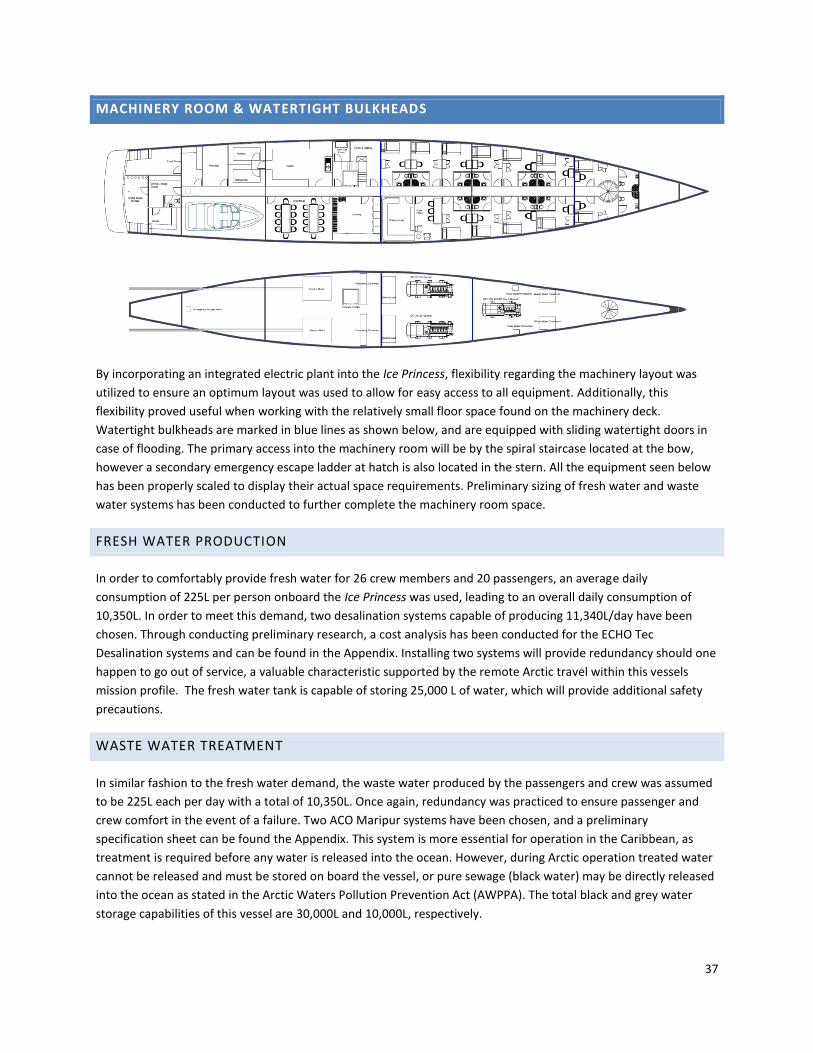
MACHINERY ROOM & WATERTIGHT BULKHEADS
By incorporating an integrated electric plant into the Ice Princess, flexibility regarding the machinery layout was
utilized to ensure an optimum layout was used to allow for easy access to all equipment. Additionally, this
flexibility proved useful when working with the relatively small floor space found on the machinery deck.
Watertight bulkheads are marked in blue lines as shown below, and are equipped with sliding watertight doors in
case of flooding. The primary access into the machinery room will be by the spiral staircase located at the bow,
however a secondary emergency escape ladder at hatch is also located in the stern. All the equipment seen below
has been properly scaled to display their actual space requirements. Preliminary sizing of fresh water and waste
water systems has been conducted to further complete the machinery room space.
FRESH WATER PRODUCTION
In order to comfortably provide fresh water for 26 crew members and 20 passengers, an average daily
consumption of 225L per person onboard the Ice Princess was used, leading to an overall daily consumption of
10,350L. In order to meet this demand, two desalination systems capable of producing 11,340L/day have been
chosen. Through conducting preliminary research, a cost analysis has been conducted for the ECHO Tec
Desalination systems and can be found in the Appendix. Installing two systems will provide redundancy should one
happen to go out of service, a valuable characteristic supported by the remote Arctic travel within this vessels
mission profile. The fresh water tank is capable of storing 25,000 L of water, which will provide additional safety
precautions.
WASTE WATER TREATMENT
In similar fashion to the fresh water demand, the waste water produced by the passengers and crew was assumed
to be 225L each per day with a total of 10,350L. Once again, redundancy was practiced to ensure passenger and
crew comfort in the event of a failure. Two ACO Maripur systems have been chosen, and a preliminary
specification sheet can be found the Appendix. This system is more essential for operation in the Caribbean, as
treatment is required before any water is released into the ocean. However, during Arctic operation treated water
cannot be released and must be stored on board the vessel, or pure sewage (black water) may be directly released
into the ocean as stated in the Arctic Waters Pollution Prevention Act (AWPPA). The total black and grey water
storage capabilities of this vessel are 30,000L and 10,000L, respectively.

38
TANK ARRANGEMENT
The tank volumes were obtained by balancing, space, COG location and vessel requirements. The relative tank
volumes were solved for by using requirements from the passenger, crew and vessel. Preliminary sizing estimates
were done on the major machinery systems including sewage, fresh water production, grey water, fuel and fuel oil.
NX was then used to balance the COG location of the vessel with the available space.
Below is a summary table of the Tank configuration volume results:
Tanks Volume m3
Bow Ballast 4
Fresh Water 25
Grey Water 30
Black Water 10
Fuel Oil 7.1
Ballast 45
Fuel 1 130
Fuel 2 150
Stern Ballast 4
The arrangement of the tanks was done in accordance with the machinery space and classification rules. Tanks are
all placed behind the crash bulkhead and Fuel tanks were all double bottom where necessary, separated from the
fresh water tanks. The black, grey and fresh water tanks were all placed near the bow as the main water making
machinery is also located there.
There is three water ballast tanks for the vessel. The ballast tanks were as far from the COG as possible to increase
their effect on draft and trim control. 4m3 tanks were placed at the bow and stern to effectively control trim and
another ballast tank was placed in between the double bottom of Fuel Tank 1. This was the lowest point on the
vessel which helps lower the CG.
Fuel had the largest tank requirement which resulted in Fuel tanks being arranged below the machinery deck, and
also on top of the machinery deck along the side of the hull and beside the machinery space. The tanks are
represented as Fuel 1 being below the machinery deck and Fuel 2 being the double bottom tanks on the machinery
deck. Below is a picture of the Tank arrangement:

39
STABILITY
This section will cover intact stability, damage stability and seakeeping analyses performed. The results were used
to determine whether the ship met SOLAS requirements.
INTACT STABILITY
The intact stability of this boat was determined under 5 loading scenarios which are summarized in Table 29. Each
condition takes into account a full load of passengers and varying levels of fuel in the tanks.
Tank 25% Fuel 75%Fuel Worst Case Lightship Full Tanks
Keel Ballast 50 25 0 0 100 Bow Ballast 50 25 0 0 100 Double Hull Ballast tank
50 25 0 0 100
Heli Fuel 25 75 50 0 100 Lube Oil tank 25 75 50 0 100 Fuel Oil 25 75 50 0 100 Greywater 75 75 50 0 100 Hottub 100 100 50 0 100 Stern Ballast 50 25 0 0 100
Table 29: Intact Stability Results
From the loading conditions, a series of GZ curves were produced using Paramarine. The software inclines the
boat and then calculates the water plane and immersed volume for the heel and loading condition. Paramarine
was also used to account for the free surface effect of tanks. From the plot of the GZ curves located in Figure 7, it
is can be seen that the hull form conforms with SOLAS requirements for general stability of ships.

40
Figure 7: Stability Curves for Various Loading Cases
DAMAGE STABILITY
The damage stability analysis of this ship was used to place the bulkheads such that this vessel would comply with
the two compartment regulation of SOLAS. A plot of the floodable lengths is located in Figure 8. The worst case
loading condition was used for this study as to produce the most conservative design possible.
Figure 8: Floodable Lengths
-8
-6
-4
-2
0
2
4
6
-44
-36
-28
-20
-12 -4 4
12
20
28
36
44
52
60
68
76
84
92
10
0
10
8
11
6
12
4
13
2
GZ Arm (m)
Heel Angle (degrees)
25% Fuel
75 Percent Fuel
Worst Case
LightShip
Full tankage

41
SEAKEEPING
This section will cover the evaluation of the sea keeping performance of the vessel. It should be noted that this
performance criteria was not of major concern when developing the hull shape as over loading/ overcrowding was
not considered an issue and the fact that the sea state in the arctic archipelago is considered fairly benign relative
to open seas.
The seakeeping analysis was performed in Paramarine with assuming a JONSWAP wave spectrum with 6 different
significant wave heights: 1.25m, 2.5m, 3.5m, 4.5m, 6m and 9m wave heights each with a wave period of 12.5
seconds.
The main goal was to ensure passenger comfort in transit during heavy weather scenarios as to assess the
potential need for stabilization. It was determined that with vertical accelerations exceeding 0.2 m/s2 cause
discomfort that would be out of place on a cruise ship. The operational plots below show the worst case of all sea
states at a variety of speeds and headings. The vertical acceleration was determined at amidships at full beam was
examined because it was assumed that the worst motions will occur there as it is the point most affected by roll
motions.
Figure 9 shows an operability plot for fast transit (15 knts)
Figure 9: Operability plot at 15 knts
From this plot, it is obvious that the favourable stability characteristics of this hull form lead to a comfortable ride
for all passengers in the vast majority of sea state conditions. It is easy to see that vertical acceleration only
exceeds the 0.2 m/s2 threshold in following seas at a wave height of 9m.

42
A plot for the RAO at max wave height was used to determine the natural frequency for roll. The natural frequency
can be observed at 0.16 Hz since this is where the maximum value of the RAO occurs.
Figure 10: RAO Simulation Results
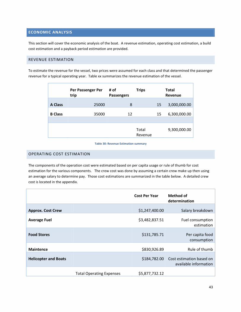
43
ECONOMIC ANALYSIS
This section will cover the economic analysis of the boat. A revenue estimation, operating cost estimation, a build
cost estimation and a payback period estimation are provided.
REVENUE ESTIMATION
To estimate the revenue for the vessel, two prices were assumed for each class and that determined the passenger
revenue for a typical operating year. Table xx summarizes the revenue estimation of the vessel.
Per Passenger Per trip
# of Passengers
Trips Total Revenue
A Class 25000 8 15 3,000,000.00
B Class 35000 12 15 6,300,000.00
Total Revenue
9,300,000.00
Table 30: Revenue Estimation summary
OPERATING COST ESTIMATION
The components of the operation cost were estimated based on per capita usage or rule of thumb for cost
estimation for the various components. The crew cost was done by assuming a certain crew make up then using
an average salary to determine pay. Those cost estimations are summarized in the table below. A detailed crew
cost is located in the appendix.
Cost Per Year Method of determination
Approx. Cost Crew $1,247,400.00 Salary breakdown
Average Fuel $3,482,837.51 Fuel consumption estimation
Food Stores $131,785.71 Per capita food consumption
Maintence $830,926.89 Rule of thumb
Helicopter and Boats $184,782.00 Cost estimation based on available information
Total Operating Expenses $5,877,732.12

44
Table 31: Operating cost estimation
CONSTRUCTION COST ESTIMATES
This section will cover the estimation of the construction cost estimate for the vessel. This was done by breaking
down the components of the ship by system category (i.e. hull, propulsion, electrical etc.) and then using a dollar
per tonne estimate to arrive a a material cost. There are also man hours per tonne correlation for each category as
well to help estimate the labour required to build the ship. All the correlation data was provided by Tom Lamb.
The estimate is summarized in tables xx and xx.
Labour Rate ($/Hour)
100 Margin Rate 10%
Overhead Rate 100% Profit Rate 5%
System Number Weight Rate (Man hrs/ton)
Man Hours
Material Rate ($/Man hour)
Material
100 462.600
120 55512 875 $404775
200 63.303 130 8229.39 16000 $1012848
300 27.240 250 6810 25000 $681000
400 35.200 650 22880 40000 $1408000
500 82.350 210 17293.5 11000 $905850
600 271.485
250 67871.33 6000 $1628911.9
800 N/A N/A 44649.055
900 N/A N/A 89298.11
Table 32: Group weight breakdown
Sub Total Materials Cost $6,041,384.92
Sub Total Labour Hours 312,543.39
Sub Total Labour Dollars $31,254,338.50
Overhead $31,254,338.50
Total Cost $68,550,061.92
Margin $6,855,006.19
Profit $3,427,503.10
BID PRICE $78,832,571.21
Table 33: Bid price summary
PAYBACK PERIOD ESTIMATION
The last section of the economic analysis consists of a payback period estimation on the capital expenditure cost of
the vessel. To arrive at this number, the yearly profit (revenue less operating costs) was divided into the
construction cost. Using this method, a payback period of 23.04 years was determined.

45
CONCLUSION AND RECOMMENDATIONS
In the conceptual design of this vessel, creative solutions to unique owner requirements were produced. Beginning
with preliminary weight estimates, academic literature was used to determine ideal hull characteristics for vessels
with similar operating regimes. Meeting these criteria, the NPL hull series was then determined to be an ideal
starting point from which resistance for the hull was determined. Propulsion and prime mover selection was then
completed to obtain primary machinery requirements and sizes. Meanwhile, general arrangements were produced
to outline the liveable space aboard the Ice Princess. Rudder and structural design used best estimates and class
rules and regulations to provide detailed approximations of the vessels controllability and structural integrity.
Models were then produced to be used in advanced stability software to provide intact and damage stability
results for the designed vessel. Auxiliary systems and cost estimates were then determined based on existing
vessels.
As only one iteration of the design spiral was completed for this conceptual design, the following is a summary of
recommendations for further detailed design:
- Due to the large degree of curvature associated with the NPL hull form, it should be adjusted to better
reflect constructability demands.
- The bow should possess a fuller form to increase usable floor space on the below decks.
- Auxiliary systems such as electrical, HVAC, compressed air, and water piping will need to be developed.
- A continuous reiteration of the weight estimates should be carried out as design changes occur to ensure
accurate approximation of stability characteristics is maintained.
- A detailed structural design and model is to be completed to ensure adequate structural strength is
achieved for this unique vessel.
As the competition for charter vessels in tropical areas becomes greater each year, charter companies are looking
to provide passengers with a unique experience to distinguish their vessel from the rest. The Ice Princess looks to
open up the beauty and remoteness of the Arctic, appealing to clients in search of adventure while maintaining the
sense of luxury and security found aboard large charter yachts.

46
WORKS CITED
International Convention for the Safety of Life at Sea. (2004). International Maritime Organization.
Authority, C. A. (2013). Standards for Offshore Helicopter Landing. In CAP 437. West Sussex: The Stationary Office.
Dan McGreer. (2014, January 24). System Based Design. Vancouver, British Columbia, Canada.
Molland, A. F. (2011). Ship Resistance and Propulsion. Cambridge University Press.


