Light Gauge Steel Framed Structure with Infill Concrete Panel (LGSFS- ICP) Technology User should check the validity of the Certificate by contacting Member Secretary, BMBA at BMTPC or the Holder of this Certificate. Name and Address of Certificate Holder: Society for Development of Composites, No. 205, Bande Mutt, Kengeri Satellite Township, Bangaluru-- 560060 Performance Appraisal Certificate No. PAC No 1028-S/2016 Issue No. 01 Date of Issue: 12.04.2016 Building Materials & Technology Promotion Council Ministry of Housing & Urban Poverty Alleviation Government of India Core 5A, First Floor, India Habitat Centre, Lodhi Road, New Delhi – 110 003 Tel: +91-11-2463 8096, 2463 8097; Fax: +91-11-2464 2849 E-mail: [email protected]Web Site: http://www.bmtpc.org
Transcript
Light Gauge
Steel Framed
Structure with
Infill Concrete
Panel (LGSFS-
ICP) Technology
User should check the
validity of the Certificate by contacting Member
Secretary, BMBA at
BMTPC or the Holder of
this Certificate.
Name and Address of Certificate Holder:
Society for Development of
Composites, No. 205, Bande
Mutt, Kengeri Satellite
Township, Bangaluru-- 560060
Performance Appraisal
Certificate No.
PAC No 1028-S/2016
Issue No. 01
Date of Issue: 12.04.2016
Building Materials & Technology Promotion Council Ministry of Housing & Urban Poverty Alleviation
PART 6 ABBREVIATIONS …………………………………………………………………….. 24
PERFORMANCE APPRAISAL CERTIFICATION SCHEME – A BRIEF…………………. 25
ANNEX A, B QAP……………………………………………………………………………….. 26
ANNEX C Drawings…………………………………………………………………..………… 28 ANNEX D Design Philosophy………………………………………………………………….. 43 ANNEX E Guidelines for Inspection………………………………………………………….. 46
Chandan
Typewritten Text
21
3
PART 1 CERTIFICATION
1.1 Certificate Holder: Society for Development of Composites
1.2.1 Name of the System– Light Gauge Steel Framed Structure with Infill Concrete Panel (LGSFS-ICP) Technology
1.2.2 Brief Description
Light Gauge Steel Framed Structure with Infill Concrete Panels (LGSFS-ICP) Technology is an innovative emerging building and construction technology using factory made Light Gauge Steel Framed Structure (LGSFS), light weight concrete and precast panels. The LGS frame is a “C” cross-section with built in notch, dimpling, slots, service holes etc. produced by computerized roll forming machine. These frames shall be assembled using metal screws to form into LGSF wall and roof structures of a building. Provisions for doors, windows, ventilators and other cutouts as required shall be incorporated in the LGSFS. A typical LGSFS for wall assembly for a building is shown in Fig. 1.
Fig. 1Typical LGS Frame Structure Wall Assembly
4
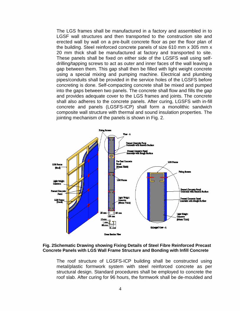
The LGS frames shall be manufactured in a factory and assembled in to LGSF wall structures and then transported to the construction site and erected wall by wall on a pre-built concrete floor as per the floor plan of the building. Steel reinforced concrete panels of size 610 mm x 305 mm x 20 mm thick shall be manufactured at factory and transported to site. These panels shall be fixed on either side of the LGSFS wall using self-drilling/tapping screws to act as outer and inner faces of the wall leaving a gap between them. This gap shall then be filled with light weight concrete using a special mixing and pumping machine. Electrical and plumbing pipes/conduits shall be provided in the service holes of the LGSFS before concreting is done. Self-compacting concrete shall be mixed and pumped into the gaps between two panels. The concrete shall flow and fills the gap and provides adequate cover to the LGS frames and joints. The concrete shall also adheres to the concrete panels. After curing, LGSFS with in-fill concrete and panels (LGSFS-ICP) shall form a monolithic sandwich composite wall structure with thermal and sound insulation properties. The jointing mechanism of the panels is shown in Fig. 2.
Fig. 2Schematic Drawing showing Fixing Details of Steel Fibre Reinforced Precast Concrete Panels with LGS Wall Frame Structure and Bonding with Infill Concrete
The roof structure of LGSFS-ICP building shall be constructed using metal/plastic formwork system with steel reinforced concrete as per structural design. Standard procedures shall be employed to concrete the roof slab. After curing for 96 hours, the formwork shall be de-moulded and
5
the wall and roof are putty finished. Door and window frames shall be fixed to the LGS frames and shutters fixed with necessary accessories. Finishing work such as laying floor tiles, fixing electrical and sanitary fixtures and painting shall be carried out using standard conventional methods. After completion of ground floor, first, second and third floors of the building shall be constructed using the same procedure that of the ground floor. The staircase, chajja and parapet walls of the building shall also be constructed using LGSFS-ICP Technology.
1.2.3 Typical Activity v/s Duration
Typical Activity v/s Duration for construction of a EWS building (about 30 sqm) using LGSFS-ICP Technology is given below: Activity Duration Pre-construction
Excavation, PCC and Raft foundation LGSF design and manufacturing LGSF transportation to site Construction Activities
1. LGFS assembly and erection Day-1 2. Fixing precast panels outside Day-2 3. Providing electrical and plumbing conduits Day-2 4. Fixing precast panels inside Day-3 5. Fixing metal/plastic formwork and steel reinforcement Day-3 6. Concrete mixing and pumping Day-4 7. Applying putty and surface finish of wall/roof Day-4 8. Fixing of floor tiles Day-5 9. Fixing of doors and windows Day-5 10. Installation of electrical and plumbing fixtures Day-5
1.3 Machinery Involved
a. Numerically controlled roll-forming machine of Pinnacle USA make of 450-900 m/hr capacity producing “C” section of 0.55 mm to 1.55 mm thickness. It also provides screw hole, service hole, web notch & lip notch
b. Universal testing machine of load 1 KN to 50 KN and having speed of 0.001 to 500 mm/min.
c. Colour mixing machine of 100 Kg capacity d. Foam concrete unit of 1.5 m3 capacity e. Vibration table f. Advance Computers installed with Pinnacle CAD software of 8 GB
ram, 2 GB graphics and 1 TB hard disc for LGSF design.
6
1.4 Manufacturing Process The manufacturing process of the constituents of LGSFS-ICP Technology shall be as follows:
1.4.1 Light Gauge Steel Frame Structure
Cold formed Light gauge steel frame super structure shall be manufactured out of min. 0.95 mm pre-treated factory finished hot dipped GI high tensile steel sheet (AZ 150 GSM Aluminium zinc alloy coated steel and having yield strength of 550MPA) which shall be as per IS 800:2007 and shall conform to AISI specification and IBC 2009. The wind loads shall be as per IS 875 (Part 3):1987. The framing section shall be cold form “C’ type of 0.55 mm to 1.55 mm thickness in required length as per structural design requirements, duly punched with dimple slots at required locations as per approved drawings. The slots shall be along center line of the web and shall be placed at 250 mm min. away from both edges of the member. The frame shall be supplied in specified dimensions and fastened with metal strip of 25 mm x 25 mm x 0.50 mm to both adjoining walls.
1.4.2 Precast Concrete Panels
Precast concrete panels shall be manufactured using cement, sand, aggregates, glass &steel fibers, water and admixtures using a design mix and curing cycle developed by the agency. It is steel fibre reinforced precast concrete panel. It gets strength as steel reinforced concrete. The overall dimensions of the panel are 1220 mm x 610 mm x 20 mm thick and the weight shall be around 36 kg. The panels shall be designed to have smooth or textured outside surface and rough inside surface. The panels shall also be designed to withstand green concrete load of 200 kg without failure and deflection shall be less than 1.0 mm. The concrete used for the panels shall be of grade M20 having water absorption less than 8%.
Mixed ratio of light weight aggregate for 1.0 Cu.m is as follows: Cement = 300 kg Sand = 400 kg Flyash = 300 kg 6mm-8mm Aggregate = 1350 kg PPfibre + steel fibre = 4.14 kg Water = 150 kg Admixtures = 150 ml
1.4.3 Concrete/Light Weight Concrete
The wall or the roof shall be constructed using M20 grade concrete and M5 –M10 grade light weight concrete. The concrete used shall be light weight and free flow. The light weight concrete shall be mixed and used at site. The concrete/light weight concrete shall be pumped into the gap between the panels.
7
1.4.4 Assembly/Connecting Screws and Anchoring Bolts
LGS frames shall be assembled together to fabricate LGSF structures using self-taping screws. The LGSF structures such as wall, roof, truss and staircase shall be connected by using special screws which shall conform to ASTM C 1513. The anchoring boards used for connecting LGSF wall structure to the foundation shall conform to relevant Indian/American Standards. Flow Charts for Light Gauge Steel and Precast Panel Manufacturing Process are as follows:
Flow Chart for Light Gauge Steel Manufacturing Process
8
Flow Chart for Precast Concrete panel Manufacturing Process
1.5 Assessment
1.5.1 Scope of Assessment 1.5.1.1 Scope of assessment included conformance of manufactured LGSF wall
structures, Precast concrete panels and Light weight concrete to the specified requirements for use as: Low rise construction buildings up to G+3 storey e.g. EWS, LIG and MIG houses, Aganwadi, Schools, Health centers, Community centers, Independent houses and Rehabilitation buildings.
1.5.2 Basis of Assessment
1.5.2.1 Assessment of the suitability of the LGSFS-ICP Technology manufactured
9
by Society for Development of Composites, Bangalore for use in building construction is based on:
(i) Inspection of 2 Police Constables Quarters and Demo building constructed using the technology by Officers of BMTPC and some of TAC members at Bangalore
(ii) Design and Construction of “2 Police Constables Quarters (G+1) building for Karnataka State Police Housing Corporation Ltd., Bangalore” by the manufacturer
(iii) Technical Report on “Light Gauge Steel Frame Structure with Infill Concrete Panels for Fast Tack and Disaster proof Housing”
(iv) Structural Analysis Report for “G+2 storey building constructed using LGSFS-ICP Technology” by M/s Nagesh Consultants, Bangalore
(v) Performance Tests conducted on “New Generation House constructed by using Foam concrete with Light Gauge Steel” by Civil-Aid Technoclinic Pvt. Ltd., Bangalore
(vi) Assessment of Quality Assurance Procedure for LGSFS-ICP Technology followed by the manufacturer as per the Quality Assurance Plan and Flow Chart for Total Quality Assurance is enclosed at Annex A & B respectively.
1.6 Use of the LGSFS-IPC Technology, Limitations, Critical Details and Durability 1.6.1 The technology shall be used for construction of Low rise residential
buildings up to G+3 storey – EWS, LIG & MIG houses, Schools, Health centers, Community centers, independent houses and rehabilitation buildings.
1.6.2 Limitation of Use
1.6.2.1 LGSFS-IPC Technology may be used for construction upto G+3 storey Buildings only.
1.6.2.2 For more than G+3 storey buildings, hybrid construction methods shall be used.
1.6.3 Critical Details The following critical details shall be followed while constructing the building:
a. 10 mm thick plaster on external walls shall be provided to take care of water proofing.
b. Guard bars and wooden/steel windows shall be provided. Aluminium sliding windows shall be avoided.
c. Sun shades shall be provided for all windows/external doors as per design.
10
1.6.4 Durability The Certificate Holder shall provide necessary structural warranty ensuring durability of the system to the user, on demand. The windows, doors and internal fittings used on specified projects are outside the scope of this Certificate and their durability must be assessed independently.
1.6.5 Scope of Inspection
Scope of inspection included the verification of production, testing facilities and performance at site including competence of technical personnel and status of quality assurance in the factory.
1.7 Conditions of Certification
1.7.1 Technical Conditions
1.7.1.1 The raw materials, the LGS Frame Structure, Precast panels and
Light weight concrete shall conform to the requirements of the prescribed specifications.
1.7.1.2 The building to be constructed using LGSFS-IPC Technology shall be designed by competent structural engineer in accordance with the specifications following relevant codal requirements, manufactured as per the details worked out in design and constructed by trained persons only with technical support or supervision by qualified engineers and builders, based on structural designs and seismic evaluation & wind forces as per the details given and this PAC.
1.7.1.3 The structural engineers and building designers associated with such type of construction should be thoroughly familiar with the various structural aspects. It is also recommended that Architects and Construction Engineers who undertake such building design and construction gain familiarity with the properties and materials, characteristics of LGSFS-IPC Technology and its applications.
1.7.2 Quality Assurance The Certificate Holder shall implement & maintain a Quality Assurance
Procedure in accordance with Total Quality Assurance given in Annex A attached with this Certificate. Quality Assurance Plan for Light Gauge Steel Frame Structure is also given in Annex B.
1.7.3 Handling of User Complaints 1.7.3.1 The Certificate holder shall provide quick redressal to consumer/user
complaints proved reasonable & genuine and within the conditions of warranty provided by it to customer/purchaser,
11
1.7.3.2 The Certificate holder shall implement the procedure included in the SQA. As part of PACS Certification he shall maintain data on such complaints with a view to assess the complaint satisfaction and suitable preventive measures taken.
1.8 Certification
1.8.1 On the basis of assessment given in Part 3 of this Certificate &subject to the conditions of certification, use & limitations set out in this Certificate and if selected, installed & maintained as set out in Part 1& 2 of this Certificate, the LGSFS-IPC Technology covered by this Certificate is fit for use set out in the Scope of Assessment.
PART 2 CERTIFICATE HOLDER’S TECHNICAL SPECIFICATION
2.1 General 2.1.1 The PAC holder shall manufacture the LGSFS-IPC in accordance with the
requirements specified in the relevant Standards. In addition it shall follow the Company standards specifying requirements of various materials used in the manufacture of the panels (see Part 5)
2.2 Specifications for the System
2.2.1 Technical Specifications 2.2.1.1 Raw materials
i. LSG Coil shall be of galvanized steel and shall conform to IS 277:1992.
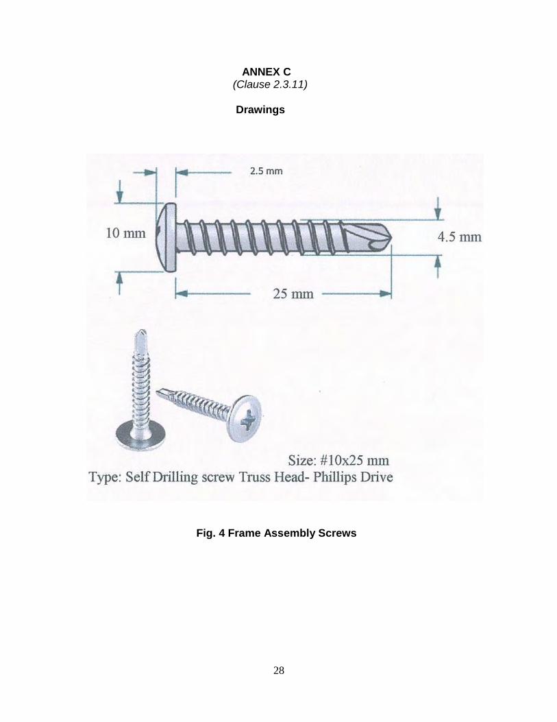
ii. Fasteners and Connectors (a) Frame assembly screws: Shall be galvanized steel screws self-
drilling type of size 10 x 25 mm having Truss-head and shall be as per ASTM C 1513-10. (See Fig. 3).
(b) Wall Erection Screws: Shall be galvanized steel screws self-drilling type of size 8 x 25 mm having Hex Washer head and shall be as per ASTM C 1513-10.(See Fig. 4).
(c) Precast Concrete Panels Fixing Screws: Shall be of galvanized steel screws self-drilling type of size 8 x 50 mm having CS head and shall be as per ASTM C 1513-10.(See Fig. 4).
(d) Wall and Foundation Anchor Bolt: Shall be of high tensile galvanized steel of size 10 x 100 mm/ 10 x 150 mm and 12 x 100 mm/ 12 x 150 mm and shall be as per ASTM C 1513-10. (See Fig. 5). iii. Foaming Chemicals: Shall be made from protein foam concentrate and FC-lite foaming agent iv. Gypsum plaster board: Shall be of size 1830 mm x 1220 mm and
12
12.5 mm to 20 mm thick and shall conform to IS 2095 (Part 1):2011 v. Water Proofing Treatment: Shall be as per IS 2645:2003 vi. Putty: Shall be as per IS 63:2006 vii. Ordinary Portland cement (OPC) shall be of 43/53 grade as per IS IS 8112:2013/ IS 12269:2013 viii. Sand and Aggregates shall be as per IS 383:2016 ix. Reinforced Steel: Shall be as per IS 1786:2008 x. Structural steel: Shall be as per IS 800:2007 xi. Steel fiber: Shall have length of 60 mm &dia. 0.75 mm and shall be as per EN 14889-1:2006 xii. Glass fiber: Shall be made from Fiber mesh 303 E3 and shall be as per EN 14889-2:2006 2.2.1.2 Light gauge steel frame/ structure
The Light gauge steel frame structure (LGSFS) shall comprise of “C “cross section studs (vertical members) and tracks (horizontal members) frames assembled together by means of mechanical screws. The schematic diagram of a typical LGSFS wall assembly is shown in 1. The structural concept of LGSFS wall is shown in Fig.3. The joints between wall & roof junctions/wall to wall junctions are designed as rigid joints
2.2.1.3 Precast concrete panels Precast Concrete Panels shall be used as facing sheets for construction of walls. Self-compacting concrete of M20 grade shall be used. Metal modes, concrete mixing machine and vibration tables shall be used for manufacturing the panels. The panels shall be designed to withstand the concrete weight pumped in between the gap of the panels without failure and buckling. The jointing mechanism of the panels is shown in Fig.2. The steel reinforced precast concrete panels (PCP), has one side rough surface and the other side smooth surface. The PCP’s are fixed on either side of Light Gauge Steel Frame Structures (LGSFS)–studs and tracks using mechanical fasteners. While fixing, the rough side of the panels are facing inside and smooth side is facing outside. Each PCP is fixed with 6 screws. Light weight concrete is pumped in to the gap between two PCPs. The concrete bonds with the rough surface of the panels. Thus, the LGSFS and PCPs are firmly joined to make a monolithic steel –concrete structure.
The concrete used for infill wall shall be light weight and free flow. The density shall be 1500-1800 Kg/m3 after adding/mixing foam or EPS beads as per the design mix developed by the agency. The light weight concrete shall be of grade M5 to M10, as required. The light weight concrete shall be mixed and used at site.
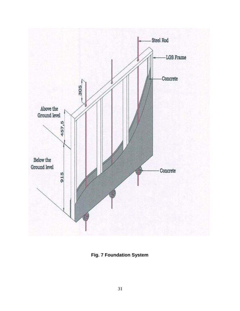
2.3 Installation/ Construction of LGSF Structures 2.3.1 Construction of Foundation and Plinth
The foundation and plinth shall be constructed confirming the floor plan of the building. The foundation depth, width, steel reinforcement, grade of concrete etc. shall be determined by structural analysis report prepared on the basis of soil condition, height of building, number of storeys, special live load requirement, if any.
2.3.2 Assembly of LGS Frames and Construction of Wall The LSG frames manufactured using numerically controlled roll forming machine using CAD design shall be transported to the construction site. The frames shall be assembled into wall structure. All the wall structures shall be connected together one by one as per the building plan by connecting screws. The wall position shall be marked on the floor and the wall structure placed on the marking. After completing the same, straightness, square and the levels shall be checked by magnetic spirit level. The bottom track shall then be connected with the floor using anchor bolts at every 600 mm bolts.
14
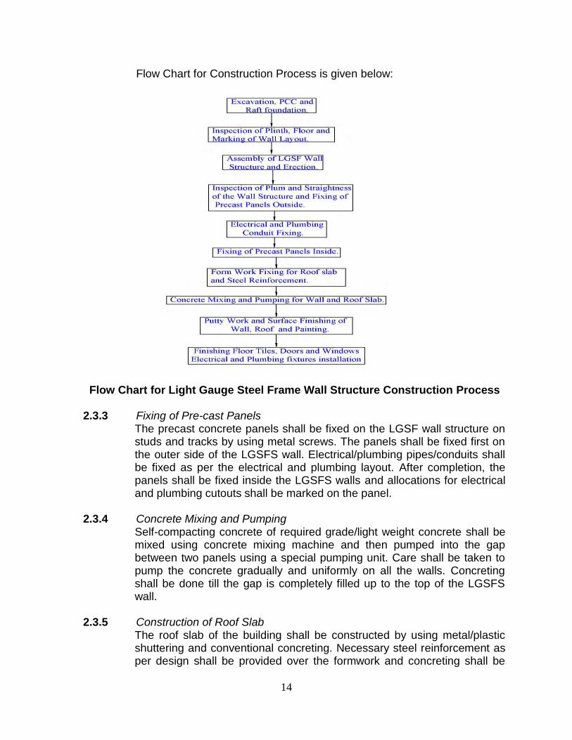
Flow Chart for Construction Process is given below:
Flow Chart for Light Gauge Steel Frame Wall Structure Construction Process
2.3.3 Fixing of Pre-cast Panels
The precast concrete panels shall be fixed on the LGSF wall structure on studs and tracks by using metal screws. The panels shall be fixed first on the outer side of the LGSFS wall. Electrical/plumbing pipes/conduits shall be fixed as per the electrical and plumbing layout. After completion, the panels shall be fixed inside the LGSFS walls and allocations for electrical and plumbing cutouts shall be marked on the panel.
2.3.4 Concrete Mixing and Pumping
Self-compacting concrete of required grade/light weight concrete shall be mixed using concrete mixing machine and then pumped into the gap between two panels using a special pumping unit. Care shall be taken to pump the concrete gradually and uniformly on all the walls. Concreting shall be done till the gap is completely filled up to the top of the LGSFS wall.
2.3.5 Construction of Roof Slab
The roof slab of the building shall be constructed by using metal/plastic shuttering and conventional concreting. Necessary steel reinforcement as per design shall be provided over the formwork and concreting shall be
15
done to required thickness. Balcony and chhajja etc., wherever required shall also be constructed using formwork. After curing the slab, shuttering shall be removed and bottom of the roof slab putty finished.
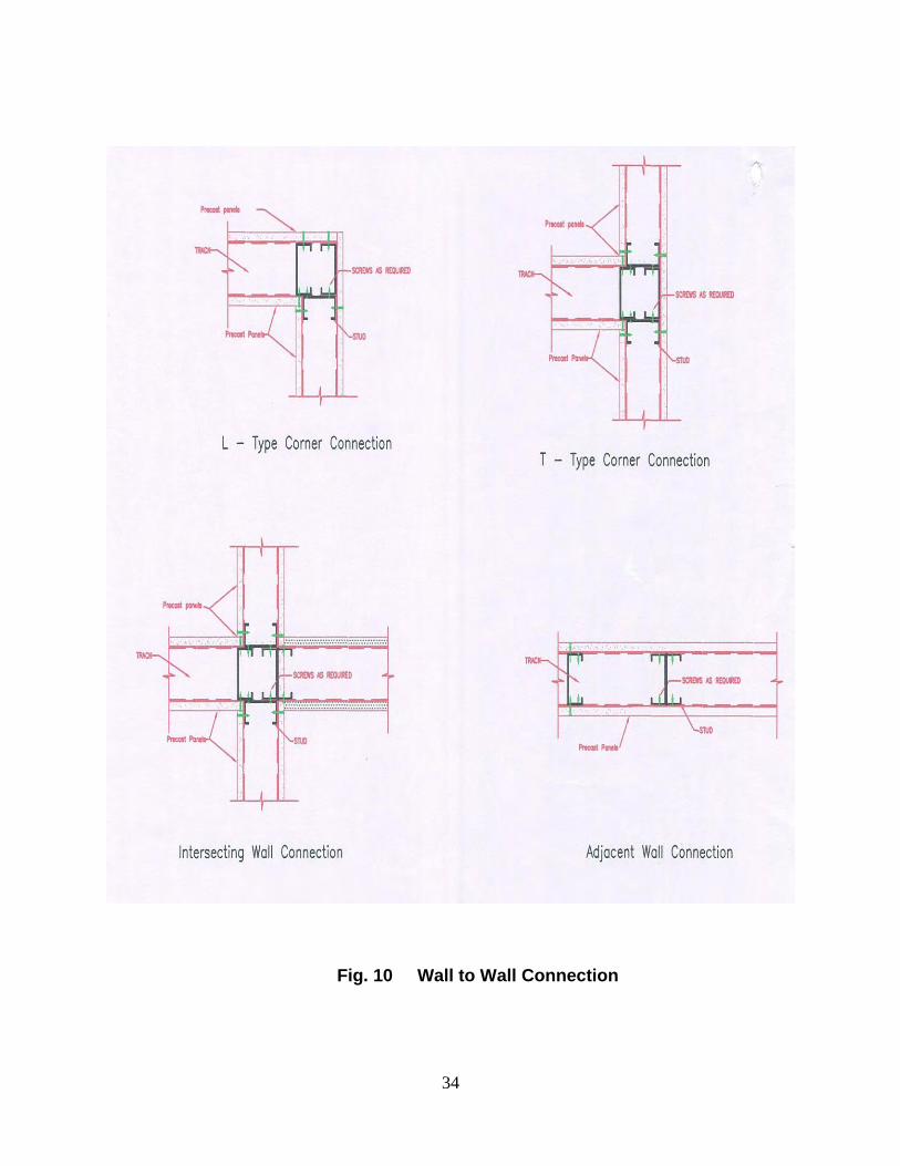
2.3.6 Reinforcement Deformed steel bars of 8mm/10mm dia as per design shall be used as shown in Figs. 6 to 12 of Annex C. 2.3.7 Staircase and Railing Staircase and balcony railing shall be fixed using conventional methods. 2.3.8 Fixing Electrical and Plumbing Fixtures The panels shall be cut at the marked locations for fixing electrical and plumbing fixtures. 2.3.9 Fixing of Doors, Windows & Ventilator Frames and Shutters
The doors, windows & ventilator frames shall be fixed on the cutouts provided in the LGSFS. The frames shall be made of WPC, uPVC and other materials, as required. Thereafter, the doors and windows shutters shall be fixed to the frames. The shutters shall be made of glass fibre/ HDF sandwich composite materials.
2.3.10 Fixing Floor Tiles
Floor tiles of desired quality and make shall be fixed to the floor, as required. Similarly, wall tiles of desired quality and make shall be fixed in the kitchen, bath and toilet using conventional methods, as required.
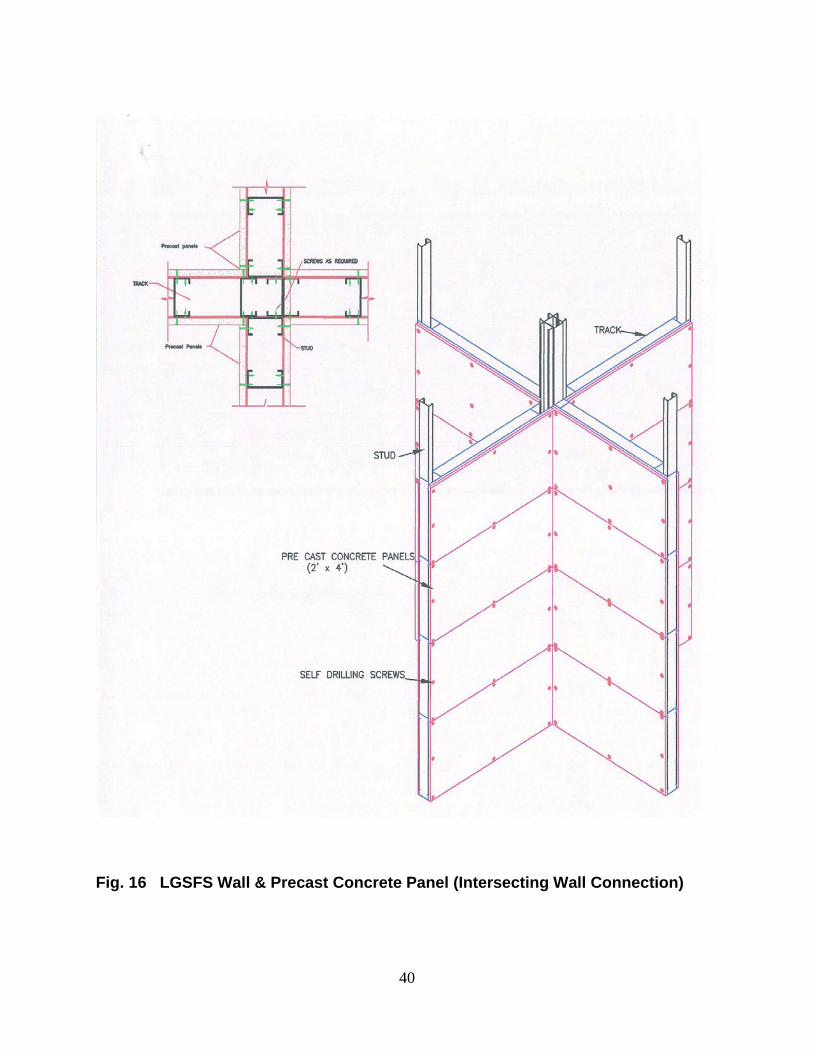
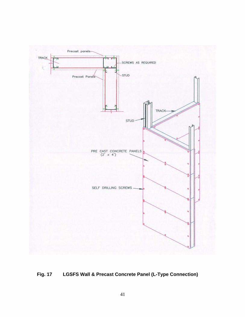
2.3.11 Surface Finishing and Painting Cement based putty shall be applied on the outside and inside walls and then painted with desired colour. The drawings showing details of foundation, various wall to wall connections, wall to roof connection and LGSFS assembly are shown in Figs.4 to 18 of Annex C. 2.4 Design Consideration
2.4.1 Structural design and analysis of LGSFS with Infill concrete panels shall
be based on relevant Indian and International standards. The technology is intended for use where Architectural drawings are available and satisfy the various requirements. The Architect and Engineer designer team of the concerned developer/owner (client) is responsible for the drawings and overall building design to comply with the various regulatory requirements applicable to the area.
2.4.2 All installations using light gauge steel structure and precast panels shall be designed by qualified structural engineer, based on the data supplied
16
by the Certificate holder.
2.4.3 The design assumptions, detailed calculations, references to necessary and detailed design drawings shall be made available on demand, if required. The structural design calculations should clearly demonstrate structural integrity and stability including connection details. Design calculations should have proper sketches annotated in English.
2.4.4 Foundation shall be specifically designed in accordance with provisions
given in IS 1904:1986. All foundations should be designed by structural engineer with appropriate reference.
2.4.5 In addition, any other requirement regarding safety against earthquake need to be ensured by the designer as per prevailing codal requirements. Design philosophy using LGSFS-ICP Technology is given in Annex D. 2.5 Inspections & Testing
Inspections & testing shall be done at appropriate stages of manufacturing process of all the components. The inspected frames and panels shall be stored & packed to ensure that no damage occurs during transportation. As part of quality assurance, regular in process inspections shall be carried out by the trained personnel of the PAC holder.
2.6 Good Practices for Installation & Maintenance
Good practice as per requirement including Do’s & Don’ts of working with LGSS System of the manufacturer shall be followed for erection and maintenance of these sections. Guidelines for Inspection of Cold-Formed Steel Structural Framing in Low Rise Buildings is given in Annex E.
2.7 Maintenance Requirements It is assumed that no special maintenance is required during intended
working life. Should repairs prove necessary, it shall ably be carried out by the trained persons using appropriate products and materials. The structures shall be regularly cleaned and painted.
2.8 Skilled /Training Needed for Installation Special training shall be required to get necessary skill set for using drill
guns for assembly of LGS frames, structures and their erection. Moreover, workers shall be trained/ oriented on handling and installation of frames, panels etc. and support system with all required safety measures taken including heavy hats, protective shoes etc.
17
2.9 Guarantees/Warranties Provided by the PAC Holder PAC holder shall provide necessary guarantees/ warranties of the system
to the client. 2.10 Responsibility
Specific design using LGSFS-ICP technology is the responsibility of the designer with the instructions, supervision and guidance of the PAC holder.
Quality of installation/construction of the system on site is the responsibility of the trade persons engaged by the agency
Quality of maintenance of the building is the responsibility of the building owner.
Providing necessary facilities and space for movement of cranes and vehicles is the responsibility of the building developer.
PART 3 BASIS OF ASSESSMENT AND BRIEF DESCRIPTION OF ASSESSMENT PROCEDURE
3.1 Assessment 3.1.1 Inspection
Inspection of a “2 Police Constable Quarters (G+1) building for Karnataka State Police Housing Corporation Ltd., and Demo building” at Bangalore constructed by the manufacturer using the same technology was done by the Officers of BMTPC and some of the TAC members. The firm has got necessary manufacturing and test facilities to construct the buildings as per design and specifications. Persons involved in testing were found to be well conversant with testing procedures required for the quality control of the system.
3.1.2 Design procedure The agency follows a well-defined design procedure based on relevant
Indian and International Standards, Codes and engineering practices. The agency has also got done the Structural design and analysis of LGSFS with Infill Concrete Panels technology for G+2 building which is enclosed at Annex. D.
18
3.2 Performance Tests Conducted on New Generation House Constructed by Using Foam Concrete with Light Gauge Steel
M/s Civil-Aid Technoclinic Pvt. Ltd., Bangalore has carried out the
performance tests on a G+1 Model House constructed in the premises of Composite Technology Park, SDC, Bangalore.
3.2.1 Salient features of the Housing unit constructed: The building has been made of galvanized light gauge (LGS) steel frame
structure which has been assembled as per the required dimensions. The upper structure comprises of walls, trusses, joists, stair case and roof structure. The LGS frames were assembled and then erected on the foundation, comprising of one course of RR masonry and two courses of solid concrete block masonry. The building consists of ground floor and part first floor only.
The light weight foam concrete has been used for construction of infill walls (mixture of cement, fine aggregate, flyash, and foaming agent in a desired ratio, the mixed foam concrete in the form of stiff slurry). The foam concrete was pumped into the gap of LGS frames which was covered on both sides by appropriate removable type of shuttering. The density of foam concrete used in this building is about 1000 to 1180 Kg/cum. The de-shuttering was carried out after 24 hours of concreting and the foam concrete allowed to self-cure. The thickness of all these walls is about 125 mm thick.
The first floor of the building has been provided with parallel chord LGS roof joists for supporting metallic deck sheets and flooring concrete. The LGS joists were fixed on the walls, the metal deck sheets fixed on joists and provided with steel reinforcement. The in-situ concrete of M20 grade was poured on the metal deck sheet and allowed to cure for a min. period of 14 days. The thickness of the roof slab varies from 75 mm to 125 mm, due to profile of decking sheet). For aesthetic look, ceiling has been provided with 8 mm thick cement fibre board fitted to the joist.
Doors consist of WPC door frames with veneer/HDF sandwich composite door shutters. Windows consist of conventional aluminum frame with glazed sliding shutters. The first floor has been constructed using the same technology except for a few changes. Instead of foam concrete, Wainer Berger hollow clay bricks were used for construction of walls up to sill level. Above sill level, 8 mm thick cement fibre board has been used to cover the light gauge steel frame on both the interior and exterior surfaces. The roof has been covered with GI sheet fixed on the sloped LGS trusses with false ceiling.
19
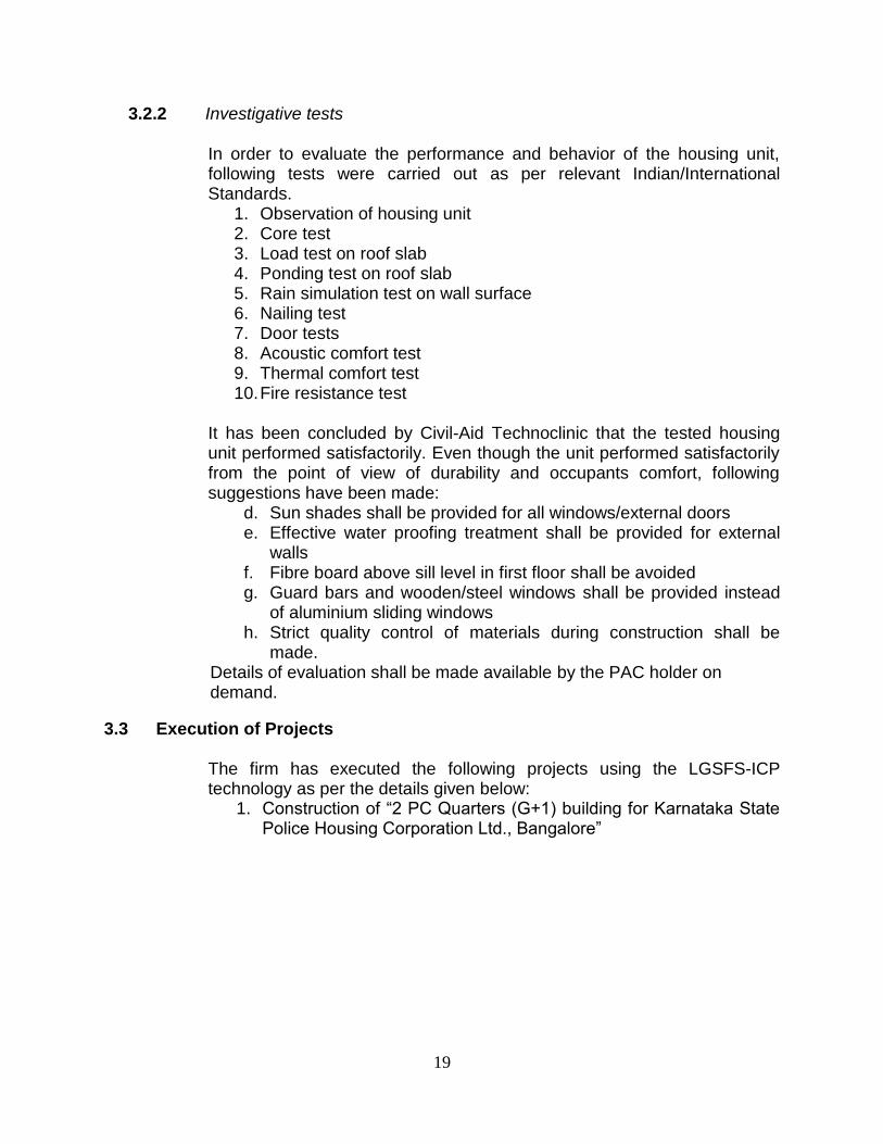
3.2.2 Investigative tests
In order to evaluate the performance and behavior of the housing unit, following tests were carried out as per relevant Indian/International Standards.
1. Observation of housing unit 2. Core test 3. Load test on roof slab
4. Ponding test on roof slab 5. Rain simulation test on wall surface 6. Nailing test 7. Door tests 8. Acoustic comfort test 9. Thermal comfort test 10. Fire resistance test
It has been concluded by Civil-Aid Technoclinic that the tested housing unit performed satisfactorily. Even though the unit performed satisfactorily from the point of view of durability and occupants comfort, following suggestions have been made:
d. Sun shades shall be provided for all windows/external doors
e. Effective water proofing treatment shall be provided for external walls
f. Fibre board above sill level in first floor shall be avoided
g. Guard bars and wooden/steel windows shall be provided instead of aluminium sliding windows
h. Strict quality control of materials during construction shall be made.
Details of evaluation shall be made available by the PAC holder on demand.
3.3 Execution of Projects
The firm has executed the following projects using the LGSFS-ICP technology as per the details given below:
1. Construction of “2 PC Quarters (G+1) building for Karnataka State Police Housing Corporation Ltd., Bangalore”
20
This certificate holder shall satisfy the following conditions: 4.1 The certificate holder shall continue to have the product reviewed by BMBA. 4.2 The product shall be continued to be manufactured according to and in compliance with
the manufacturing specifications and quality assurance measures which applied at the time of issue or revalidation of this certificate. The Scheme of Quality Assurance separately approved shall be followed.
4.3 The quality of the product shall be maintained by the certificate holder. 4.4 The product user should install, use and maintain the product in accordance with the
provisions in this Certificate. 4.5 This certificate does not cover uses of the product outside the scope of this appraisal. 4.6 The product is appraised against performance provisions contained in the standards
listed in Part-V. Provisions of any subsequent revisions or provisions introduced after the date of the certificate do not apply.
4.7 Where reference is made in this Certificate to any Act of Parliament of India, Rules and
Regulations made there under, statutes, specifications, codes of practice, standards etc. of the Bureau of Indian Standards or any other national standards body and the International Organization for Standardization (ISO), manufacturer’s company standards, instruction/manual etc., it shall be construed as reference to such publications in the form in which they were in force on the date of grant of this Certificate (and indicated in Part V to this Certificate)
4.8 The certificate holder agrees to inform BMBA of their distributors / licensees whenever
appointed by him and agrees to provide to BMBA a six monthly updated list thereof. 4.9 The certificate holder agrees to provide to BMBA feedback on the complaints received,
the redressal provided, and the time taken to provide redressal on complaint to complaint basis as soon as redressal is provided. BMBA agrees to provide the certificate holder the user feedback received by it, if any.
4.10 If at any time during the validity period, PACH is unable to fulfill the conditions in his
PAC, he should on his own initiative suspend using the PAC and notify Chairman, TAC the date from which he has suspended its use, the reason for suspension and the period by which he will be able to resume. He shall not resume without the prior permission of BMBA. He shall also inform, simultaneously, his agents, licensees, distributors, institutional, government, public sector buyers, other buyers and all those whom he has informed about his holding the PAC. He shall also inform all those who buy his product(s) during the period of suspension. He shall provide to BMBA at the earliest the list of who have been so informed by him.
PART4 STANDARD CONDITIONS
22
PART 5 LIST OF STANDARDS & CODES USED IN ASSESSMENT
5.1 These Standards are referred for carrying out particular tests only and do not specify the
requirement for the whole product as such. 5.1.1 IS 63: 2006 -- Specifications for putty 5.1.2 IS 277:2003 – Specifications for Galvanized Steel Sheets (Plain &corrugated) 5.1.3 IS 383:2016–Specifications for fine and coarse aggregates from natural resources 5.1.4 IS 456:2000 –Code of practice for Plain & Reinforced concrete (fourth revision) 5.1.5 IS 800:2007 – Code of practice fort general construction in steel 5.1.6 IS 801:1975 – Code of practice for use of Cold Formed Light gauge Steel structural members in General building construction 5.1.7 IS 875 (Parts1 to 5):1987 – Code of Practice for Design Loads (other than earthquake) for buildings & structures 5.1.8 IS 1346:1991 – Code of practice for water proofing of roofs 5.1.9 IS 1786: 2008–Specifications for high strength deformed steel bars and wires for concrete reinforcement 5.1.10 IS1893:2002 – Criteria for Earthquake Resistant Design of Structures 5.1.11 IS 1904:2005 – Code of Practice for design and construction of foundations in soils: General requirements. 5.1.12 IS 2062:2011– Specifications for hot rolled medium & high tensile structural steel 5.1.13 IS 2095 (Part1):2011–Specifications for Gypsum plaster boards– plain 5.1.14 IS 2645:2003 –Specifications for integral water proofing compounds for cement, mortar and concrete 5.1.15 IS 8112:2013 – Specifications for Ordinary Portland Cement – 43 grade (2nd Revision) 5.1.16 IS 9012:1978 – Recommended practice for shotcreting 5.1.17 IS 12269:2013 – Specifications for Ordinary Portland Cement – 53 grade 5.1.18 EN 14889-1:2006 – Standard specifications for steel fibres for concrete 5.1.19 EN 14889-2:2006–Standard specifications for glass fibres for concrete 5.1.20 BS 5950 (Part 5):1998 –Code of practice for design of cold formed thin gauge sections 5.1.21 ASTM A307—Standard specification for Carbon steel Bolts& studs 5.1.22 ASTM A568– Standard specifications for thickness tolerances of cold rolled steel sheets & coils 5.1.23 ASTM A 653(9) – Standard specifications for steel sheet, zinc coated or zinc-iron alloy coated 5.1.24 ASTM C1513-10 – Standard specifications for steel tapping screws for cold formed steel framing connections 5.1.25 AISI S 200-07 – Design of cold formed structural members using the direct Strength method 5.2 Company Standards of the PAC holder – The branded design & specifications of the raw materials and finished product are as submitted by the manufacturer. The PAC holder has to make available the company standards to the consumers according to which testing have been done.
24
PART 6 ABBREVIATIONS
Abbreviations
BMBA Board of Agreement of BMTPC BMTPC Building Materials and Technology Promotion Council CPWD Central Public Works Department ED Executive Director of BMTPC IO Inspecting Officer MS Member Secretary of BBA PAC Performance Appraisal Certificate PACH PAC Holder PACS Performance Appraisal Certification Scheme SQA Scheme of Quality Assurance TAC Technical Assessment Committee (of BMBA)
Building Materials & Technology Promotion Council (BMTPC) was set up by the Government of India as a body under the Ministry of Housing &Urban Poverty Alleviation to serve as an apex body to provide inter-disciplinary platform to promote development and use of innovative building materials and technologies laying special emphasis on sustainable growth, environmental friendliness and protection, use of industrial, agricultural, mining and mineral wastes, cost saving, energy saving etc. without diminishing needs of safety, durability and comfort to the occupants of buildings using newly developed materials and technologies. During the years government, public and private sector organizations independently or under the aegis of BMTPC have developed several new materials and technologies. With liberalization of the economy several such materials and technologies are being imported. However, benefits of such developments have not been realized in full measure as understandably the ultimate users are reluctant to put them to full use for want of information and data to enable them to make informed choice. In order to help the user in this regard and derive the envisaged social and economic benefits the Ministry of Housing &Urban Poverty Alleviation has instituted a scheme called Performance Appraisal Certification Scheme (PACS) under which a Performance Appraisal Certificate (PAC) is issued covering new materials and technologies. PAC provides after due investigation, tests and assessments, amongst other things information to the user to make informed choice. To make the PACS transparent and authentic it is administered through a Technical Assessment Committee (T AC) and the BMTPC Board of Agreement (BMBA) in which scientific, technological, academic, professional organizations and industry interests are represented. The Government of India has vested the authority for the operation of the Scheme with BMTPC through Gazette Notification No. 1-16011/5/99 H-II in the Gazette of India No. 49 dated 4th December, 1999. Builders and construction agencies in the Government, public and private sectors can help serve the economic, development and environmental causes for which the people and Government stand committed by giving preference to materials and technologies which have earned Performance Appraisal Certificates. Further information on PACS can be obtained from the website: www.bmtpc.org
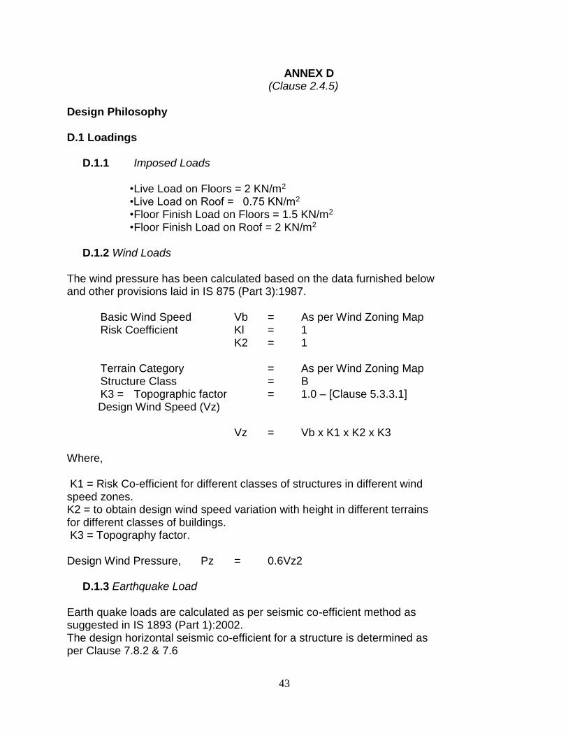
• Live Load on Floors = 2 KN/m2 •Live Load on Roof = 0.75 KN/m2 • Floor Finish Load on Floors = 1.5 KN/m2 • Floor Finish Load on Roof = 2 KN/m2
D.1.2 Wind Loads The wind pressure has been calculated based on the data furnished below and other provisions laid in IS 875 (Part 3):1987. Basic Wind Speed Vb = As per Wind Zoning Map Risk Coefficient Kl = 1 K2 = 1 Terrain Category = As per Wind Zoning Map Structure Class = B K3 = Topographic factor = 1.0 – [Clause 5.3.3.1] Design Wind Speed (Vz) Vz = Vb x K1 x K2 x K3 Where, K1 = Risk Co-efficient for different classes of structures in different wind speed zones. K2 = to obtain design wind speed variation with height in different terrains for different classes of buildings. K3 = Topography factor. Design Wind Pressure, Pz = 0.6Vz2 D.1.3 Earthquake Load Earth quake loads are calculated as per seismic co-efficient method as suggested in IS 1893 (Part 1):2002. The design horizontal seismic co-efficient for a structure is determined as per Clause 7.8.2 & 7.6
44
Ah = Z I Sa 2 R g Z – Zone factor for Zone III – Moderate Seismic Intensity = 0.16 I – Importance factor = 1.0 R – Ordinary RC Moment resisting frame = 3.0 Sa –Average response acceleration co-efficient which depends on soil g types, natural period and damping values. T – 0.09h / √d as per Clause 7.6.2 of IS 1893 (Part-1): 2002, Where, h=Height of Building in meters, excluding Basement. d= Base dimension of the building at the plinth level in m, along the considered direction of the lateral force. Soil Type – Type II D.1.3.1 Calculation of Horizontal Seismic Coefficient (Ah) • Along X- Direction • Along Y- Direction D.2 Basic Loads and Load Combinations
The various loads are combined in accordance with the stipulations in IS 875 (Part 5):1987. Wherever imposed load is combined with earthquake load the appropriate part of the imposed load as specified in Clause 7.4, and Table 8 of IS 1893 (Part 1):2002, is adopted both for evaluating earthquake effect and for combined load effects, used in such combination.
Analysis will be carried out using ETABS Version software. Working Load Cases, Factored Load Cases and Wind Load Cases
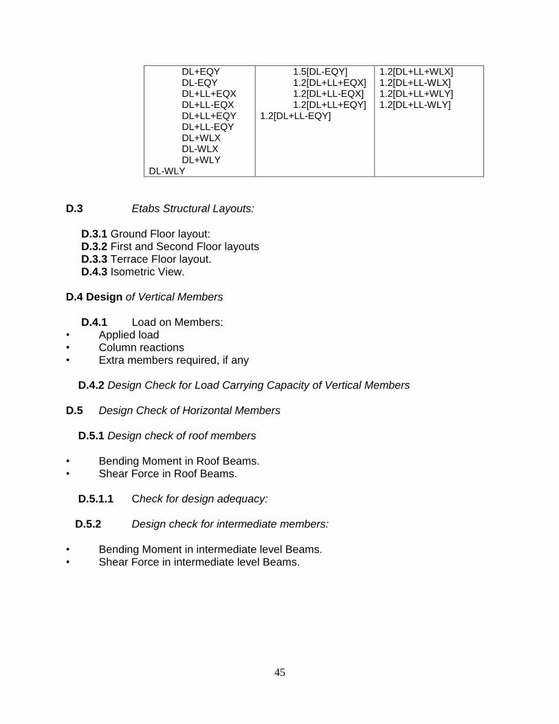
D.3 Etabs Structural Layouts: D.3.1 Ground Floor layout: D.3.2 First and Second Floor layouts D.3.3 Terrace Floor layout. D.4.3 Isometric View. D.4 Design of Vertical Members D.4.1 Load on Members: • Applied load • Column reactions • Extra members required, if any D.4.2 Design Check for Load Carrying Capacity of Vertical Members D.5 Design Check of Horizontal Members D.5.1 Design check of roof members • Bending Moment in Roof Beams. • Shear Force in Roof Beams. D.5.1.1 Check for design adequacy: D.5.2 Design check for intermediate members: • Bending Moment in intermediate level Beams. • Shear Force in intermediate level Beams.
46
ANNEX E (Clause 2.6) GUIDELINES FOR INSPECTION OF COLD-FORMED STEEL STRUCTURAL FRAMING IN LOW RISE BUILDINGS E.1 Materials
E.1.1 Steel Verification:
(i)Cold-formed steel structural members shall match with the specified size, type, mechanical properties and spacing. (ii) Each member should bear a legible sticker, stamp, etc. spaced at a max. of 2.44m c/c indicating the steel designation, thickness, min. yield strength, name of manufacturer etc. (iii)Member sizes i.e. length of webs, flanges and material thickness should be the same as specified in the approved design. (iv)The min. metallic coating weight requirements of structural members should be CP60 unless another coating weight is specified.
E.1.2 Member Condition: The framing members shall not be damaged. Damaged members shall be replaced or repaired in accordance with approved design.
E.1.3 Web Holes: The factory punch outs or field penetrations shall conform
with the approved design. Web holes should not be spaced closer than60mm or located closer than 25 cm from a bearing condition.
E.1.4 Field Nuts and Notches: There shall be no field cuts or notches through
the flanges or lips of any structural members. E.2 Connections
E.2.1 Screw Connections:
(i)The screws installed shall comply with the approved design. Thescrews shall satisfy shear and pull out requirements, diameter and point style in relation to combined thickness of all connected steel frame members. (ii)Steel-to-steel and structural sheathing-to-steel shall be inspectedto ensure that they extend through the steel connection to a min.penetration of three exposed threads through the last materialjoined. (iii)The screws shall penetrate individual components in the connection without causing permanent separation between thecomponents. (iv)Missing screw heads, if any, shall be replaced. For screw fasteners in steel-to-steel connections to be fully effective, the min. C to C spacing and edge distance should be three times the normal dia except when the edge is parallel to the direction of applied force. The min. edge distance of screw fasteners should be 1.5 times the normal dia.
47
Self-drilling screws shall be checked for pull out strength as per the calculated value at the component as well as system level.
E.2.2 Pneumatically Driven Pins:
(i) Installed pins shall comply with the approved design. (ii) Ensure that pins are fully driven and have a min. penetration of 6 mm through the last material joined.
E.2.3 Welding: (i) All welding shall be done as per approved design. (ii) Welded areas should be treated with the approved treatment to Retain the corrosion resistance of the welded area.
E.2.4 Bolted Connections: Bolts shall meet or exceed the requirements of
ASTM A307 and should be installed with nuts and washers unless specified otherwise. C to C spacing of bolts should be min. of three bolt diameters.
E.2.5 Low Velocity Fasteners: Type of fastener, spacing and edge distance
requirements shall be inspected for conformance to an approved design.
E.2.6 Other Connections: All other type of connections shall also be installed as per the approved design.
E.3 Foundations
E.3.1 Bearing Surfaces: Ensure that the foundation is level and free from
defects. If the foundation is not level, provide a uniform bearing surface with a max. gap of 6mm between the bottom track or rim track and the foundation.
E.3.2 Ground Contact: Ensure that the framing is not in direct contact with the ground unless specified otherwise. Framing not in direct contact with the ground should be installed at a height above the ground in accordance with the applicable building code.
E.4 Floor, Roof and Ceiling Framing
E.4.1 Plumpness: Floor and ceiling joists and trusses should be installed in
plumb and level except where specifically designed as sloping members.
E.4.2 Bearing Width: Floor and ceiling joists and trusses should be installed with full bearing over the width of the wall beneath having a min.38mm bearing.
E.4.3 Joint Stiffeners and Compression Blocking: The bearing stiffness and
compression blocking shall conform to the approved design or standard.
48
E.4.4Joist and Rafter Bracing: Joist and rafter bracing shall be installed as the
approved design or standard. Bracing typically consist of gypsum board, structural-rated sheathing, steel strapping with blocking or X-bracing.
E.4.5 Joist and Rafter Spacing: No Joist or rafter spacing unless approved by
the design professional. Joints lapped over an interior support are not considered spliced.
E.4.6 Floor Cantilevers and Openings: Framing at floor cantilevers and
openings shall be installed as per the approved design or standard.
E.4.7Floor and Roof Trusses: The floor and roof trusses shall be installed as per the approved design or standard.
E.5 Wall Framing
E.5.1 Stud End Bearing: Ensure that studs have square end cuts and are
seated tight against the stud track. For axial load bearing applications, gaps between the ends of the stud the track web should not be greater than 3mm. For curtain wall applications, gaps between the ends of the stud the track web should not be greater than 6mm.
E.5.2 Stud Alignment:
(i)Identify weather the stud wall system indicated is either “in-line” or “wall top plate distributor” system and that loads are properly transferred as appropriate to the system end. (ii)For “in-line” framing, where the roof trusses, rafter and floor joists are aligned over a bearing stud, the acceptable tolerance for alignment is as per Fig. 2 unless otherwise specified. (iii)For “wall top plate distributor” system, the top track shall be properly framed as per the approved design or standard.
49
Alignment Framing
Fig. 1
E.5.3 Foundation Connection: Steel-framed walls should be anchored to the foundation or floors as per the approved design or standard.
E.5.4 Stud Bracing: Ensure that stud bracing shall be installed as per the approved design or standard. Bracing typically consist of gypsum board, structural-rated sheathing, steel strapping with blocking or a combination of gypsum board, structural rated sheathing, steel strapping with blocking.
E.5.6 Splicing: studs and other structural members should not be spliced without an approved design. Track splices should be made continuous by means of splicing the track as per the approved design or standard.
E.6 Shear Walls
E.6.1 Sheathed Shear Walls: The following shall conform to the approved design or standard:
(i)Sheathes type panels shall be as per current building codes or other approved sheathing; (ii)Roof diaphragm boundary to block fastener size and spacing; (iii)Roof blocking to wall top track fastener size and spacing;
50
(iv) Panel sheathing boundary and field fastener size and spacing; (v) Bottom wall track through floor diaphragm to rim track fastener size and spacing; (vi) Floor rim track to top wall track fastener size and spacing; (vii) Foundation track fastener type, size and spacing; (viii)Hold-down size, location and fastener requirement.
E.6.2 “X-braced” Shear Walls: It shall be confirmed that diagonal straps are installed taut and remain taut after all dead loads have been placed on the walls.
E.6.3 Miscellaneous: The following shall be verified: (i) Screws or pins shall be driven so that the head is not more than 1.5mm below surface of sheathing; (ii) Sheathing shall be installed with continuous strap or other blocking detail at horizontal intermediate panel edges, if applicable; (iii) Edge fasteners at multiple studs shall be driven into the member connected to the hold-down device; (iv) Bottom track connection, to the foundation or structure, shall meet all requirements carried out on the approved design or standard; (v)Blocking and/or shear transfer connections at the top of the walls shall meet all requirements carried out on the approved design or standard; (vi) Shear wall ends shall have boundary studs, min. two, per current code assemblies, or as required by the approved design or standard; (vii) Where hold-downs are indicated, all hold-downs shall be attached through the webs of two studs, unless there is a single boundary stud required by the approved design or standard; (viii)Where anchor bolts are used, nuts and washers shall be properly installed. E.7 Built-up Beams and Headers
E.7.1 Built-up Beam and Header Composition: The built-up beams and headers shall be inspected to make sure they conform to the approved design or standard. The members used to make built-up beams and headers shall be inspected for punch-outs or other penetrations. Penetrations should be allowed only if shown on the approved design or standard, unless approved.
E.7.2 Beam Stiffeners: Beams require stiffeners at the ends and at the interior locations where point loads occur, unless specified otherwise. E.8 Floor and Roof Trusses
E.8.1 Truss Chord, Web Members and Panel Points: Pre-engineered trusses
51
may be designed by a specialized designer rather than the design professional. The truss design drawings shall be checked for design loads and truss spacing to conform compliance with the approved design.
E.8.2 Truss Orientation: Orientation of installed trusses shall be checked with particular attention to parallel chord trusses and trusses with interior bearings.
E.8.3 Truss-to-Wall Connection: The connections of trusses to the top of the wall shall conform to the approved design or standard.
E.8.4 Truss Bracing: Truss bracing shall be as per the approved design or standard and the truss design drawings.
E.8.5 Truss Anchorage: The approved design shall be checked to determine if the truss hold-down connections are required. If the hold-down typically will attach to the truss and to the aligned stud below.
E.8.6 Shear Connector Blocking at Exterior Bearing Walls: The approved design or standard shall be checked to determine if a strap and intermediate blocking or continuous blocking are required for the transfer of shear from the roof to wall diaphragms.