Name of the Candidate IDNo. Place of Research Work and Organization Proposed Supervisor Name Qualification Designation Mukesh Kumar 2011PhDENGG003 JKLU, Jaipur Dr. Kanad Ray Ph.D. Organization Associate Professor Institute of Engineering & Technology JKLU, Jaipur Proposed Topic of Research Design of an Ultra Wideband Antenna with WLAN Rejection for Wireless Communication Objectives of the Proposed Research: 1. The main Objective is to design a suitable or optimal Ultra wide band antenna. 2. The first important requirement for designing an UWB antenna is the extremely wide impedance bandwidth. Bandwidth of 7.SGHz is required for a workable UWB antenna. 3. The return loss for the entire ultra-wide band should be in the range of less than -1OdB 4. The radiation efficiency is required to be quite high. 5. Low directivity is desired. 6. The gain should be as uniform as possible for different directions Background of the Proposed research Introduction: The Federal Communications Commission (FCC) approved the frequency band in the range of 3.1 to 10.6 GHz in 2002[1]. This motivated both academic and industrial communities to develop compact antennas for UWB applications. The UWB technology gives high-speed data transmission rate with low power consumption. The applications of Ultra Wideband antenna are in wireless communications, medical imaging, radar and indoor positioning. The 1
Transcript
Name of the Candidate
IDNo.
Place of Research Work
and Organization
Proposed Supervisor
Name
Qualification
Designation
Mukesh Kumar
2011PhDENGG003
JKLU, Jaipur
Dr. Kanad Ray
Ph.D.
Organization
Associate Professor
Institute of Engineering & Technology
JKLU, Jaipur
Proposed Topic of Research
Design of an Ultra Wideband Antenna with WLAN Rejection for Wireless Communication
Objectives of the Proposed Research:
1. The main Objective is to design a suitable or optimal Ultra wide band antenna.
2. The first important requirement for designing an UWB antenna is the extremely wide
impedance bandwidth. Bandwidth of 7.SGHz is required for a workable UWB
antenna.
3. The return loss for the entire ultra-wide band should be in the range of less than -1OdB
4. The radiation efficiency is required to be quite high.
5. Low directivity is desired.
6. The gain should be as uniform as possible for different directions
Background of the Proposed research
Introduction:
The Federal Communications Commission (FCC) approved the frequency band in the range
of 3.1 to 10.6 GHz in 2002[1]. This motivated both academic and industrial communities to
develop compact antennas for UWB applications. The UWB technology gives high-speed
data transmission rate with low power consumption. The applications of Ultra Wideband
antenna are in wireless communications, medical imaging, radar and indoor positioning. The
1
merits of printed antenna such as light weight, small size and low profile make them an
attractive for UWB antenna development. A conventional microstrip antenna has drawback
of narrow impedance bandwidth [2].
In February 14,2002, the Federal Communications Commission (FCC) amended the Part 15
rules which govern unlicensed radio devices to include the operation of UWB devices[3]. The
FCC also allocated a bandwidth of 7.5GHz, i.e. from 3.1GHz to 10.6GHz to UWB
applications [1], is a revolutionary approach for short-range high-bandwidth wireless
communication. Differing from traditional narrow band radio systems (with a bandwidth
usually less than 10% of the centre frequency) transmitting signals by modulating the
amplitude, frequency or phase of the sinusoidal waveforms, UWB systems transmit
information by generating radio energy at specific time instants in the form of very short
pulses thus occupying very large bandwidth[3] .
Due to the transmission of very short pulses, UWB radio propagation will provide very high
data rate which may be up to several hundred Megabytes per second, and it is difficult to
track the transmitting data, which highly ensures the data security. For the same reason, the
transmitting power consumption of UWB systems is extremely low in comparison with that
of traditional narrowband radio systems. UWB technology is widely employed in many
applications such as indoor positioning, radar/medical imaging and target sensor data
collection.
One of the challenges for the implementation of UWB systems is the development of a
suitable or optimal antenna. The first important requirement for designing an UWB antenna is
the extremely wide impedance bandwidth. Bandwidth of 7.5GHz is required for a workable
UWB antenna. And commonly, the return loss for the entire ultra-wide band should be in the
criterion of less than -10dB [3]. Next, for indoor wireless communication, omnidirectional
property in radiation pattern is demanded for UWB antenna. Therefore, low directivity is
desired and the gain should be as uniform as possible for different directions [4].
Another important requirement is the radiation efficiency. Since the power transmitted into
space is very low, the radiation efficiency is required to be quite high (normally the radiation
efficiency should not be less than 70%). Last but not least, UWB technology is mainly
employed for indoor and portable devices, the size of the UWB antennas is required to be
sufficiently small so that they can be easily integrated into various equipments. Extensive
investigations are carried out on the development of UWB antennas from the past to present
[5].
2
Literature Review of Research Topic:
The micro-strip antenna is "an antenna that consists of thin metallic conductor bonded to a
thin grounded dielectric substrate" [2]. The radiation of micro-strip antenna is based on the
discontinuities of the antenna element. The radiation characteristics of a rectangle micro-strip
antenna can be estimated from the field distribution of the patch.
A Micro-strip patch antenna is very simple in construction as shown in figure 1. Most
commonly used Micro-strip patch antennas are rectangular and circular patch antennas. These
patch antennas are used in simple, as well as widest and most demanding applications.
Patch
Feed line
Fig. 1 - An edge-fed patch antenna
Micro-strip antennas have some merits and some de-merits.
Merits:
- Low weight, low volume and thin profile.
- Low fabrication cost, easily mass producible.
- Linear and circular polarizations are possible.
- Easily integrated with microwave integrated circuits.
- Capable of dual and triple frequency operations.
- Feed lines and matching networks can be fabricated simultaneously.
3
De Merits:
Micro-strip antennas have some demerits:
- Low efficiency.
- Low Gain.
- Low power handling capacity.
- Excitation of surface waves.
- Polarization purity is difficult to achieve.
- Complex feed structures require high performance arrays.
- Unacceptably high levels of cross polarization and mutual coupling within the array
environment at high frequencies.
Types of Micro-strip Antennas:
There are different types of Micro-strip antennas which are classified based on their
physical parameters. These different types of antennas have many shapes and dimensions.
Micro-strip antennas can be classified into four groups:
- Micro-strip patch antennas
- Micro-strip dipoles
- Printed slot antennas
- Micro-strip traveling wave antennas
Micro-strip Patch antennas: -
A Micro-strip patch antenna is a thin conducting patch of any shape and size on one
side of a dielectric substrate, the other side having a ground plane. Several feeding
mechanism can be used for the micro-strip antenna and they offer the designer many
parameters to optimize the antenna performance. Flexibility of the micro-strip antenna
configurations was the main reason why these structures were chosen to be designed[2].
4
--./
The patch in the antenna is made of a conducting material Cu (Copper) or Au (Gold) and this
can be of any shape Fig 2 as rectangular, circular, triangular, elliptical or some other shape
[2] as shown below.
ISquare Rectangular Dipole Circular
Triangular Circular Ring Elliptical
Figure 2: Common shapes of the patch antennas which are in use [2].
The basic antenna element is a thin conductor of length L and width W. It is deposited on a
dielectric substrate with dielectric constant sr, height h and a ground plane. The rectangular
patch antenna is designed so that it can operate at the specified resonance frequency [2]. The
length for the patch does depend on the height of the dielectric substrate. The length of the
patch normally would be 0.333", < L < 0.5 "" where", is the free space wavelength.
The physical length of the patch can be calculated by the simple formula from [2]
L_-,f' = L + 211L!::J j .
Lsrr = Effective length of the patch
L = Physical length of the patch
~L = Extension of length of the patch due to fringing fields
The height h of the dielectric substrate that supports the patch usually ranges between 0.003 '"
< h < 0.05", Value of dielectric constant (e.) of the substrate is usually between 2.19 and 12.
5
The patch of the antenna is excited by feed which may be edge feed or a probe feed.
When the patch is excited by feed, a charge distribution is established between the ground
plane and the underneath of the patch. The underneath of the patch is charged positive and
the ground plane is charged negative after excitation. The attractive forces are setup between
the planes i.e., patch underneath and the ground plane.
These patch antennas are narrow band devices with a bandwidth ~ 10% of f..., and also having
poor radiation efficiency. A good performance from the patch antenna can be expected with a
thick dielectric substrate of low dielectric constant as this gives better efficiency, larger
bandwidth and better radiation [13]. But these types of antennas are larger in size.
Feed Techniques and Modeling of Micro-strip Antennas:-
Micro-strip patch antenna has various feeding techniques.
1. Micro-strip line
2. Coaxial probe
3. Aperture coupling
4. Proximity coupling
Design process of micro-strip antennae-
There is no universal mathematical method to determine the geometry of an antenna
based on specific requirements and the design process of the antennas is done through
analysis an antenna geometry is constructed and parameters are calculated for that structure.
Then dimensions of the antenna are altered until the desired properties are achieved. The
transmission and cavity model are used to analyze micro-strip antennas [2].
In February 14, 2002, the Federal Communications Commission (FCC) amended the Part 15
rules which govern unlicensed radio devices to include the operation ofUWB devices[3]. The
FCC also allocated a bandwidth of 7.5GHz, i.e. from 3.1GHz to 10.6GHz to UWB
applications [1], is a revolutionary approach for short-range high-bandwidth wireless
communication. Differing from traditional narrow band radio systems (with a bandwidth
usually less than 10% of the centre frequency) transmitting signals by modulating the
amplitude, frequency or phase of the sinusoidal waveforms, UWB systems transmit
6
information by generating radio energy at specific time instants in the form of very short
pulses thus occupying very large bandwidth[3] .
Due to the transmission of very short pulses, UWB radio propagation will provide very high
data rate which may be up to several hundred Megabytes per second, and it is difficult to
track the transmitting data, which highly ensures the data security. For the same reason, the
transmitting power consumption of UWB systems is extremely low in comparison with that
of traditional narrowband radio systems. UWB technology is widely employed in many
applications such as indoor positioning, radar/medical imaging and target sensor data
collection.
One of the challenges for the implementation of UWB systems is the development of a
suitable or optimal antenna. The first important requirement for designing an UWB antenna is
the extremely wide impedance bandwidth. Bandwidth of 7.5GHz is required for a workable
UWB antenna. And commonly, the return loss for the entire ultra-wide band should be in the
criterion of less than -10dB [3]. Next, for indoor wireless communication, omnidirectional
property in radiation pattern is demanded for UWB antenna. Therefore, low directivity is
desired and the gain should be as uniform as possi ble for different directions [4].
Another important requirement is the radiation efficiency. Since the power transmitted into
space is very low, the radiation efficiency is required to be quite high (normally the radiation
efficiency should not be less than 70%). Last but not least, UWB technology is mainly
employed for indoor and portable devices, the size of the UWB antennas is required to be
sufficiently small so that they can be easily integrated into various equipments. Extensive
investigations are carried out on the development of UWB antennas from the past to present
[5].
Gap in Existing Research
Interference is a serious problem for UWB application systems. UWB having a
bandwidth of7.5GHz i.e. from 3.1GHz to 1O.6GHz.UWB applications requires the rejection
of the interference with existing wireless local area network (WLAN) technologies such as
IEEE 802.11a in the USA (5.15-5.35GHz, 5.725-5.825GHz). So that UWB transmitters can
not cause any electro-magnetic interference on nearby communication systems such as
Wireless LAN (WLAN) applications.
7
Methodology: -
Following steps are implemented:-
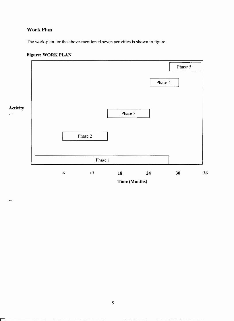
Phase l ; Literature Survey
A detailed literature survey will be carried out to understand the theory of ultrawide band
antenna, it is necessary to be equipped with the basic knowledge of micro strip antenna. Since
the ultrawide band antenna having band of7.5GHz. UWB technology is widely employed in
many applications such as indoor positioning, radar/medical imaging and target sensor data
collection.
Continuous literature survey will be carried out to collect the information required during
various stages of the proposed research. The source of this literature survey will be various
available journals like, IEEE, IETE, Journal of wireless communication, e-books, internet
sites and e-journals source.
Phase 2: Designing ofuwb antenna
An Ultrawide band antenna will be designed for operation from 3.1GHz tol0.6 GHz.
Standard formulae and standard design procedure will be used for drawing the 3D structure
of basic antenna.
HFSS software will be used to construct the 3D model and to simulate antenna
characteristics.
Phase 3: Designing of an uwb antenna with band notch
An Ultrawide band antenna will be designed for operation from 3.1GHz tolO.6 GHz. With
band notched characteristic by cutting slots in the patch to reject the band from 5.1GHz to
5.8 GHz which is for WLAN.
Phase 4: Analysis of Results
All the graphs will be drawn like return loss, VSWR, smith chart, radiation patterns and all
the results will be verified with standard requirement.
Phase 5: Conclusion and Thesis writing
In this phase, all the experimental and theoretical work carried out in different phases will be
documented in the form of thesis.
8
r---
Work Plan
The work-plan for the above-mentioned seven activities is shown in figure.
Figure: WORK PLAN
Activity
Phase 5
Phase 4
Phase 3
Phase 2
Phase 1
12 18 24
Time (Months)
30
9
References
[1.] Federal Communications Commission, Washington, DC, "FCC report and order on