41
Naming Standards Physical, logical, services & organizations Date: 31-10-2008 Version No.: 1.5 All Rights Reserved NORDUnet A/S
Naming Standards Physical, logical, services & organizations Date: 31102008 Version No.: 1.5 All Rights Reserved NORDUnet A/S

Naming Standards
Date:
Version:
All Rights Reserved:
31102008 1.5 NORDUnet A/S
Page 2 of 41
Naming standards contents
1 Objective .................................................................................................. 4
2 Target group ............................................................................................. 4
3 Introduction .............................................................................................. 4
3.1 Examples on abbreviations that could be used ......................................... 5
3.1.1 Running series system ....................................................................... 7
4 Physical naming standard ........................................................................... 9
4.1 SITE ID ............................................................................................ 12
4.1.1 SITE SYNTAX .................................................................................. 12
4.1.2 How to make the SITE ID unique ...................................................... 12
4.2 Rack ID ............................................................................................ 13
4.2.1 Rack SYNTAX .................................................................................. 13
4.2.2 How to make the rack space ID unique .............................................. 15
4.3 Sub Rack ID ...................................................................................... 16
4.3.1 Sub rack SYNTAX ............................................................................ 16
4.4 Height units ...................................................................................... 17
4.4.1 Height unit SYNTAX ......................................................................... 17
4.5 Equipment, Slot and Port ID ................................................................ 17
4.5.1 Equipment SYNTAX ......................................................................... 18
4.5.2 Virtual equipment ............................................................................ 18
4.5.3 External Network Equipment ............................................................ 18
4.5.4 Equipment shelf .............................................................................. 19
4.5.5 Equipment shelf SYNTAX .................................................................. 19
4.5.6 Slot, card and ports ......................................................................... 19
4.5.7 Slot, card and port SYNTAX .............................................................. 21
4.6 Connection and Cable ID..................................................................... 22
4.6.1 Cable ID ........................................................................................ 23
4.6.2 Cable ID SYNTAX ............................................................................ 24
4.6.3 How to make the cable ID unique ...................................................... 24
4.6.4 Tube and Duct ID ............................................................................ 24
4.6.5 Tube and Duct ID SYNTAX ................................................................ 25
4.6.6 How to make the tube and duct ID unique.......................................... 25

Naming Standards
Date:
Version:
All Rights Reserved:
31102008 1.5 NORDUnet A/S
Page 3 of 41
5 Logical naming standards ......................................................................... 26
5.1 Link ID ............................................................................................. 29
5.1.1 The link ID naming SYNTAX .............................................................. 30
5.1.2 How to make the link ID unique ........................................................ 30
5.1.3 Examples of used link ID’s ................................................................ 30
5.2 Path ID ............................................................................................. 31
5.2.1 The path ID naming SYNTAX ............................................................ 31
5.2.2 How to make the path ID unique ....................................................... 32
5.2.3 Examples of used path ID’s .............................................................. 32
5.3 Circuit ID .......................................................................................... 33
5.3.1 The circuit ID naming SYNTAX .......................................................... 34
5.3.2 How to make the circuit ID unique .................................................... 34
5.3.3 Examples of used circuit ID’s ............................................................ 34
5.4 Service ID ......................................................................................... 35
5.4.1 The service ID naming SYNTAX ......................................................... 35
5.4.2 How to make the service ID unique ................................................... 36
5.4.3 Examples of used service ID’s ........................................................... 36
5.5 Logical summary................................................................................ 36
6 Linking logical naming standards to organizations ........................................ 38
6.1 Organization ..................................................................................... 38
6.1.1 The organization naming SYNTAX ...................................................... 38
6.2 Contact............................................................................................. 39
6.2.1 The contact naming SYNTAX ............................................................. 39
7 Documentation ........................................................................................ 40
8 Abbreviations .......................................................................................... 41
Naming Standards
Date:
Version:
All Rights Reserved:
31102008 1.5 NORDUnet A/S
Page 4 of 41
1 Objective
This guide is to be used for creation of network documentation naming standards within NORDUnet Operations. The document also serves as a building document for related appendixes related to network documentation.
2 Target group
This document is intended for staff in NORDUnet Operations, and related personnel to the NORDUnet network.
3 Introduction
The naming standards have been developed by NORDUnet to be as generic as possible. The work to make these standards have taken a little over a year, and is the results of input and collaboration with many of NORDUnet partners both internally and externally. The document can be used as a guideline within all NORDIC NRENs.
The naming standards can be fully or partly implemented if parts of the standard are not needed. The specification of names, codes, etc. and what naming standards are implemented within the individual NREN network shall be separately specified in the allocated appendix.
The document has been divided into mainly two naming parts;
1. Physical parts: Naming of the physical parts refer to the labelling of all installed parts of the network. All physical elements on a site and between sites are covered by the physical parts naming standard.
2. Logical parts: Naming of the logical parts refer to the usage of the network resources. The resources provided by the network can be named on several levels. All the logical parts are virtual and non physical naming within the NMS.
The physical naming standard can be expanded into deeper levels of information, as illustrated in Figure 1, if required and the different levels of naming can be individually specified by the NREN in the allocated appendix.

Naming Standards
Date:
Version:
All Rights Reserved:
31102008 1.5 NORDUnet A/S
Page 5 of 41
The logical naming standard is expandable through a reservation of number series that allows the NREN to define additional levels of information if required. Specific information on series used for logical naming shall be stated in the appendices. Read more on the running series in section 3.1.1.
Section 6 describes the usage for organizations and contacts, which can be related to the services provided.
3.1 Examples on abbreviations that could be used
The NREN’s are required to specify the names used on all levels in the appendices of the document.
No specific thoughts on why to use abbreviations on site names and network names was done, just that an identifier had to be found for each site and network, that would not be in conflict with other networks that the NREN connects to.
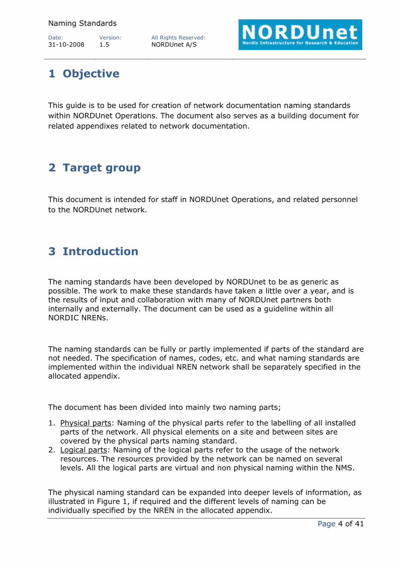
The abbreviations must be meaningful; preferably a mnemonic name so it tells the operators what the equipment is used for. The list must be simple, and cover as many releases of any type of equipment, to be future proof. Some examples can be seen in table 1.
Figure 1

Naming Standards
Date:
Version:
All Rights Reserved:
31102008 1.5 NORDUnet A/S
Page 6 of 41
SITE name abbreviation Full name
CSC
FRE
HMB1
HMB2
HEU
ORE
OSC
TUG
UNI
USI
CSC Helsinki
Fredhäll
Hamburg Wendelstrasse 1
Hamburg Wendelstrasse 2
Helsinki University
Ørestaden
Oslo Centrum
Tulegatan
Uni•C
Oslo University
Country name abbreviation
Full name
DK
SE
NO
FI
IS
Denmark
Sweden
Norway
Finland
Iceland
Network name abbreviation
Full name
FK
FU
NU
RH
SU
UN
Forskningsnettet
FUNET
NORDUnet
RHnet
SUNET
UNINETT
Naming Standards
Date:
Version:
All Rights Reserved:
31102008 1.5 NORDUnet A/S
Page 7 of 41
Equipment name abbreviation
Full name
LM
TSS
ILA
RAM
Light Manager
Transport Service Switch
In Line Amplifier
Raman Amplifier
Table 1
3.1.1 Running series system
The running series system is a generalisation for this document, and is, as this document, intended as a guidance for producing appendixes of all kinds related to naming standards. The running series system should be used as it is designed, but there are no limitations as to how to use the running series system in a new appendix.
The running series system is basically a running number with an identifier starting from the digit from 0 to 9 following a letter identifier from A to Z. These numbers and letters are used to differentiate between circuits, paths, links, patch cables and so forth. If the identifier numbers or letters are exhausted, a second number or letter can be applied to meet the needs.
This will give the following syntax for a running series system.
< x >< incrementing number start = 0 >
And if needed
< xx >< incrementing number start = 0 >
Where X and XX is represented by a number or a letter.
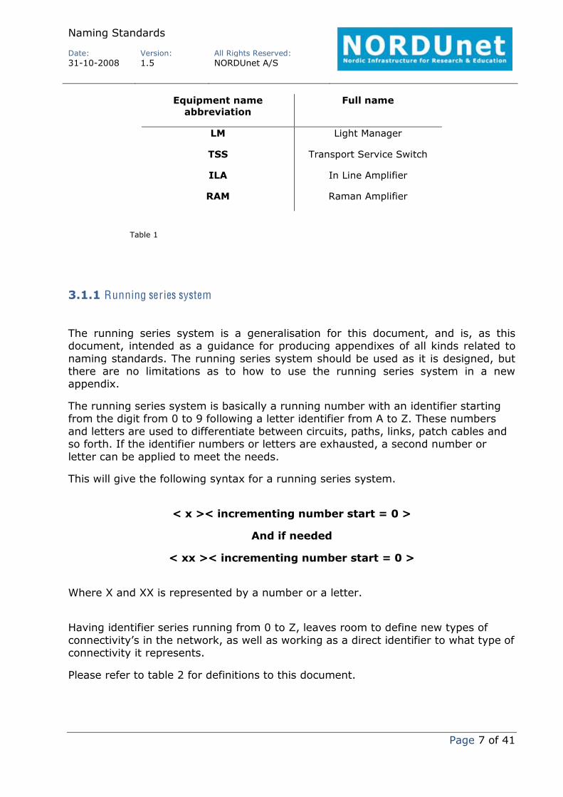
Having identifier series running from 0 to Z, leaves room to define new types of connectivity’s in the network, as well as working as a direct identifier to what type of connectivity it represents.
Please refer to table 2 for definitions to this document.
Naming Standards
Date:
Version:
All Rights Reserved:
31102008 1.5 NORDUnet A/S
Page 8 of 41
Running series Use of Remarks
0000000 Cables Reserved cable ID’s
1000000 Links Reserved link ID’s
2000000 N/A Not in use
3000000 N/A Not in use
4000000 Paths Reserved path ID’s
5000000 Circuits Reserved circuit ID’s
6000000 N/A Not in use
7000000 N/A Not in use
8000000 N/A Not in use
9000000 N/A Not in use
S000000 Services Reserved service ID’s
Table 2
Table 2 definitions in bold are fixed, and cannot be overruled by any appendix.
Any appendix is free to use any identifier free, or “invent” a new identifier from the syntax description.
Naming Standards
Date:
Version:
All Rights Reserved:
31102008 1.5 NORDUnet A/S
Page 9 of 41
4 Physical naming standard
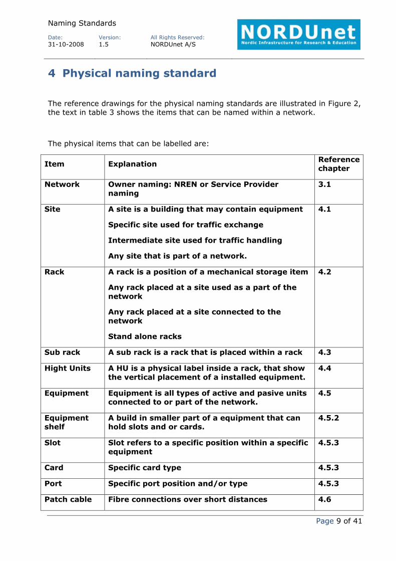
The reference drawings for the physical naming standards are illustrated in Figure 2, the text in table 3 shows the items that can be named within a network.
The physical items that can be labelled are:
Item Explanation Reference chapter
Network Owner naming: NREN or Service Provider naming
3.1
Site A site is a building that may contain equipment
Specific site used for traffic exchange
Intermediate site used for traffic handling
Any site that is part of a network.
4.1
Rack A rack is a position of a mechanical storage item
Any rack placed at a site used as a part of the network
Any rack placed at a site connected to the network
Stand alone racks
4.2
Sub rack A sub rack is a rack that is placed within a rack 4.3
Hight Units A HU is a physical label inside a rack, that show the vertical placement of a installed equipment.
4.4
Equipment Equipment is all types of active and pasive units connected to or part of the network.
4.5
Equipment shelf
A build in smaller part of a equipment that can hold slots and or cards.
4.5.2
Slot Slot refers to a specific position within a specific equipment
4.5.3
Card Specific card type 4.5.3
Port Specific port position and/or type 4.5.3
Patch cable Fibre connections over short distances 4.6

Naming Standards
Date:
Version:
All Rights Reserved:
31102008 1.5 NORDUnet A/S
Page 10 of 41
Leased circuit
Refers to a third party communication connections
4.6
Fibre Physical fibre string connecting sites 4.6
Trunk A collection of patch cables, leased circuits or fibres
A trunk can be fully used by the NREN
4.6
Cable Cables containing many optical fibres
Cables containing many electrical wires
A cable can contain trunks
A cable can be shared between many providers
4.6
Tube Tubes can contain cables
Tubes can contain single fibres
4.6.5
Duct Ducts are constructed channels that contains the tubes or cables
4.6.5
Table 3
Naming Standards
Date:
Version:
All Rights Reserved:
31102008 1.5 NORDUnet A/S
Page 11 of 41
Rack
Sub rackUnit
SlotSlot
Slot
PortPort Port: Port ID
Rack: Rack ID
Sub rack: Sub rack ID
Unit: EQ type-EQ no.
Slot: Slot ID
Site
ODR
Rack
Subrack
Unit
Site
Unit
ODR tray
Power rack
Breaker
ODR
ODF tray
ODR
ODF tray
Site
Patch cable
Powercable
Nomenclatures
Country: Country codeSite: Site IDUnit: EQ type-EQ no.Patch cable: Cable ID
DDF
DDF Plate
Unit
Coaxcable
Auxunit Leased circuit
Auxcable
3’rd party Network
Site: Site IDRack: Rack IDSub rack: Sub rack IDUnit: EQ type-EQ no.Power rack: Rack IDBreaker: Sub rack IDPower cable: Cable IDAux unit: EQ type-EQ no.Aux cable: Cable IDODR: EQ type-EQ no.ODR tray: Sub rack IDPatch cable: Cable IDDDF: Rack IDDDF plate: Sub rack IDCoax cable: Cable ID
Leased circuit: Cable ID Fibre: Cable IDTrunk: Cable IDCable: Cable IDTube: Tube IDDuct: Duct ID
Country: Country codeSite: Site IDODR: EQ type-EQ no.ODR tray: Sub rack IDPatch cable: Cable ID
Aux
Fibre
Physical Layer
Tube
Duct
CableTrunk
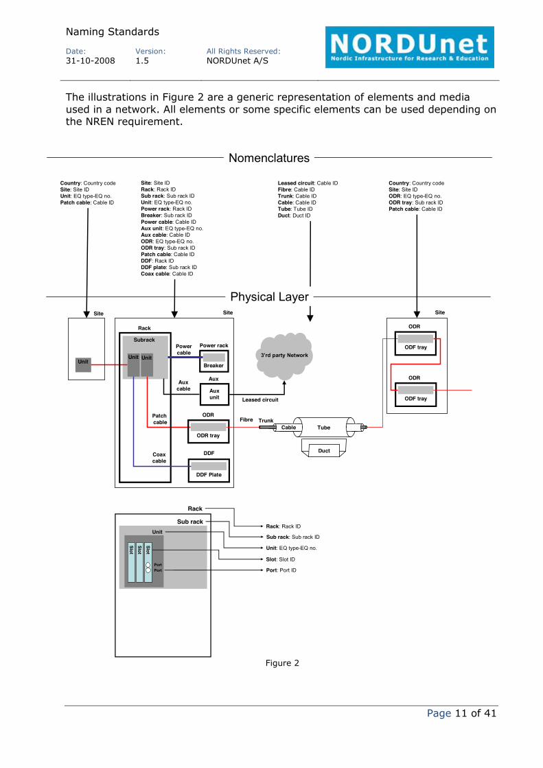
The illustrations in Figure 2 are a generic representation of elements and media used in a network. All elements or some specific elements can be used depending on the NREN requirement.
Figure 2
Naming Standards
Date:
Version:
All Rights Reserved:
31102008 1.5 NORDUnet A/S
Page 12 of 41
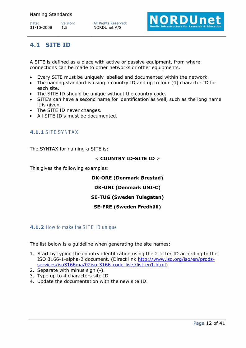
4.1 SITE ID
A SITE is defined as a place with active or passive equipment, from where connections can be made to other networks or other equipments.
Every SITE must be uniquely labelled and documented within the network. The naming standard is using a country ID and up to four (4) character ID for each site.
The SITE ID should be unique without the country code. SITE’s can have a second name for identification as well, such as the long name it is given.
The SITE ID never changes. All SITE ID’s must be documented.
4.1.1 SI T E SY N T A X
The SYNTAX for naming a SITE is:
< COUNTRY IDSITE ID >
This gives the following examples:
DKORE (Denmark Ørestad)
DKUNI (Denmark UNIC)
SETUG (Sweden Tulegatan)
SEFRE (Sweden Fredhäll)
4.1.2 How to make the SI T E ID unique
The list below is a guideline when generating the site names:
1. Start by typing the country identification using the 2 letter ID according to the ISO 31661alpha2 document. (Direct link http://www.iso.org/iso/en/prodsservices/iso3166ma/02iso3166codelists/listen1.html)
2. Separate with minus sign (). 3. Type up to 4 characters site ID 4. Update the documentation with the new site ID.

Naming Standards
Date:
Version:
All Rights Reserved:
31102008 1.5 NORDUnet A/S
Page 13 of 41
4.2 Rack ID
A rack is a container of passive and active equipment in all forms. The racks are found in all shapes and forms, both wall and floor mountable, ETSI and 19 inch native racks. Common for all rack types are, they use a HU (Height Unit) indicator, or can have an indicator labelled to the front of the rack. With the HU indicator a rack can be designed to use its capacity to the fullest.
Every rack must be labelled and documented uniquely within the network. Naming standard is using static floor tile objects to make the ID unique for each rack within a site. - If the site is not with floor tiles or already have a different ID system assigned in this site, this is accepted as the racks ID (as long as there is a known system for the ID of a rack)
- A rack ID defines a position in the site. - Rows are defined by letters starting from AZ - Columns are defined by digits starting from 1 to 99; a leading zero must be used for numbers 1 to 9.
- Rows and columns are dividable into 4, for explanation see section 4.2.2 and Figure 3, and must therefore be defined with minimum 0 after the row indicator to indicate the tile is not divided.
- Rows and columns must be separated by full stop (.). A moved rack must change ID. All rack ID’s must be documented.
4.2.1 Rack SY N T A X
The SYNTAX for naming a rack is:
< XY.ZZ >
Syntax symbol
Reserved numbers and letters
Explanation
X AZ Defined row at the site
0 Undefined row at the site
Y A + B Defines the position and orientation of a half rack (300 x 600 mm)
C + D Defines the position and orientation of a half rack

Naming Standards
Date:
Version:
All Rights Reserved:
31102008 1.5 NORDUnet A/S
Page 14 of 41
(300 x 600 mm)
NREN specified letter
Specified alternative rack types in the allocated NREN appendix
0 A full rack (600 x 600 mm)
1 A half rack (300 x 600 mm). Unknown orientation.
ZZ 199
Defined column at the site
00 Undefined column at the site
Table 4
The syntax in table 4 is also illustrated in Figure 3.
The NREN can if required, and specified in the allocated appendix, expand the syntax to higher level of letters and numbers, e.g. XXYY.ZZZ.
This gives the following examples:
C0.01 (60x60cm rack at row C and position 1, ref. figure 3)
C0.02 (60x60cm rack at row C and position 2, ref. figure 3)
C0.03 (60x60cm rack at row C and position 3, ref. figure 3)
CA.04 (30x60cm rack at row C and position 4, ref. figure 3)
CB.04 (30x60cm rack at row C and position 4, ref. figure 3)
CC.05 (60x30cm rack at row C and position 5, ref. figure 3)
CD.05 (60x30cm rack at row C and position 5, ref. figure 3)
01.00 (30x60cm rack, undefined row, column and orientation, ref. figure 3)
0C.00 (60x30cm rack at undefined row and column. Defined orientation, ref. figure 3)
00.00 (undefined rack, row, column and orientation)

Naming Standards
Date:
Version:
All Rights Reserved:
31102008 1.5 NORDUnet A/S
Page 15 of 41
4.2.2 How to make the rack space ID unique
This applies to sites with elevated floors using floor tiles of 600*600 mm, but can also be applied to sites with other size tiles or sites where a letter and digits print can be mounted on the walls.
If a floor plan does not exist to a specific site, it is advisable to make an outlined floor plan for the site.
1. Start by entering the most obvious door to the site (if more than one entrance).
2. Go to the far left corner from that door and mark the starting point for the site. See Figure 3. A stating point can just be defined if this is easier.
3. Always start with row, then column. 4. If half size racks are to be installed, the rows and columns need to be divided. 5. Dividing as shown on Figure 3 from left to right, or top to bottom, will divide a tile into A, B, C or D sides.
6. Define rows by a letter AZ followed by division indicator zero for no division or A, B, C or D as shown on Figure 3.
The rack space ID starts with row letter, indicator of division and ending with column number. Half size rack can be divided as depicted on position C.04 and C.05. When dividing a row A and B must be used, if dividing by column, use C and D.
Figure 3
Naming Standards
Date:
Version:
All Rights Reserved:
31102008 1.5 NORDUnet A/S
Page 16 of 41
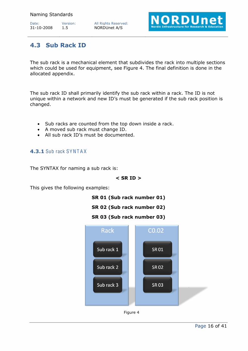
4.3 Sub Rack ID
The sub rack is a mechanical element that subdivides the rack into multiple sections which could be used for equipment, see Figure 4. The final definition is done in the allocated appendix.
The sub rack ID shall primarily identify the sub rack within a rack. The ID is not unique within a network and new ID’s must be generated if the sub rack position is changed.
Sub racks are counted from the top down inside a rack. A moved sub rack must change ID. All sub rack ID’s must be documented.
4.3.1 Sub rack SY N T A X
The SYNTAX for naming a sub rack is:
< SR ID >
This gives the following examples:
SR 01 (Sub rack number 01)
SR 02 (Sub rack number 02)
SR 03 (Sub rack number 03)
Figure 4

Naming Standards
Date:
Version:
All Rights Reserved:
31102008 1.5 NORDUnet A/S
Page 17 of 41
4.4 Height units
Typical racks or cabinets are 43HU high, and comes in width sizes of 19 inch and 21 inch. Other sizes are available on the market, but common for all is, they have a unit placement definition available through the mounting holes from top to bottom. Some racks are delivered with a label system to the rail of mounting holes, some are not. In order to further make it easy to find small or large equipments installed inside racks, the following applies.
All racks installed to sites, must have a HU label on the mounting rails. All equipment ID’s must be documented with a HU ID. A leading zero must be used for the first 9 numbers, making all numbers on the label consist of 2 digits.
HU shall start from the floor and up, beginning with 00/01 up to xx. This ensures units installed in HU10 is always installed the same height from the floor.
4.4.1 H eight unit SY N T A X
The SYNTAX for naming height units is:
< Leading zero for x<10 >< x >
This gives the following examples:
0102030405303132
4.5 Equipment, Slot and Port ID
The definition of equipment can include passive ODR’s, passive optical equipments, and active equipments such as SDH equipments, WDM terminals and IP routers. Common denominator for all kind of equipments is that they are installed on a site.
There might be a use for secondary names to any defined equipment, if used, this name and how to define it, should be described in a relevant document for the document in question. This document does not dictate a standard for using secondary names.
All equipments must be labelled and documented uniquely within the network.
Naming Standards
Date:
Version:
All Rights Reserved:
31102008 1.5 NORDUnet A/S
Page 18 of 41
The NREN’s specific naming standard shall be specified in the allocated appendix stating the type name of the equipment must indicate the equipment use and purpose.
All equipment ID’s must be documented.
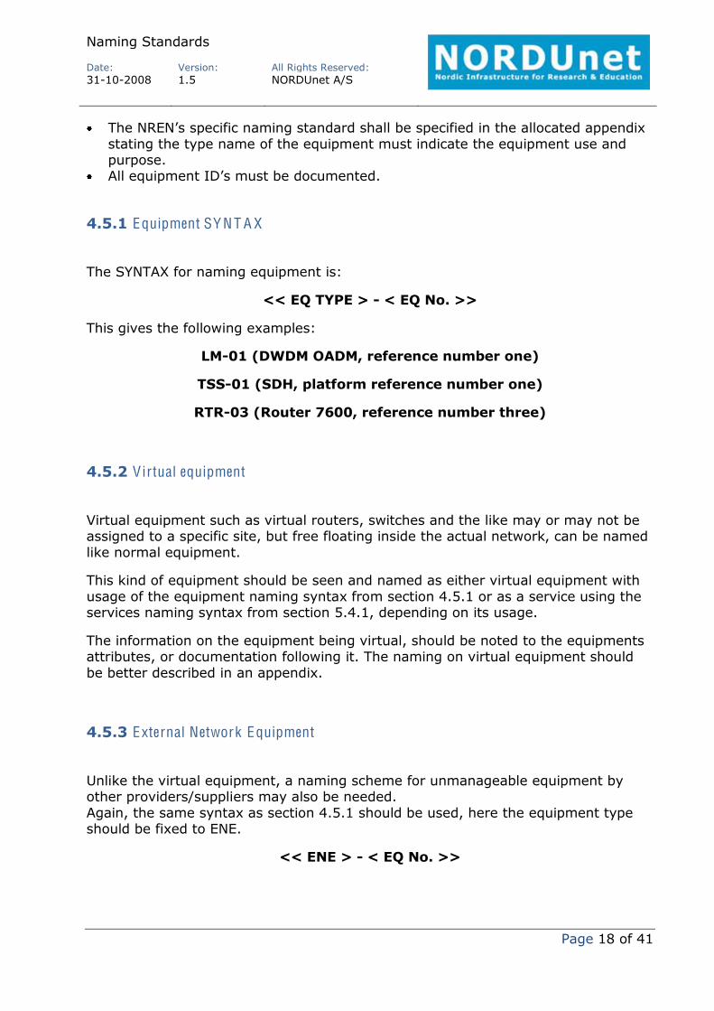
4.5.1 Equipment SY N T A X
The SYNTAX for naming equipment is:
<< EQ TYPE > < EQ No. >>
This gives the following examples:
LM01 (DWDM OADM, reference number one)
TSS01 (SDH, platform reference number one)
RTR03 (Router 7600, reference number three)
4.5.2 Virtual equipment
Virtual equipment such as virtual routers, switches and the like may or may not be assigned to a specific site, but free floating inside the actual network, can be named like normal equipment.
This kind of equipment should be seen and named as either virtual equipment with usage of the equipment naming syntax from section 4.5.1 or as a service using the services naming syntax from section 5.4.1, depending on its usage.
The information on the equipment being virtual, should be noted to the equipments attributes, or documentation following it. The naming on virtual equipment should be better described in an appendix.
4.5.3 External Network Equipment
Unlike the virtual equipment, a naming scheme for unmanageable equipment by other providers/suppliers may also be needed. Again, the same syntax as section 4.5.1 should be used, here the equipment type should be fixed to ENE.
<< ENE > < EQ No. >>

Naming Standards
Date:
Version:
All Rights Reserved:
31102008 1.5 NORDUnet A/S
Page 19 of 41
4.5.4 Equipment shelf
Many different types of equipments take up different space in a rack. They can be defined by a specific size, or expandable. The latter raising the need for a shelf definition.
A shelf is an expandable part of active equipment. Typically a shelf corresponds to a shelf, or in some cases to a sub rack, within an active equipment management system.
4.5.5 Equipment shelf SY N T A X
The SYNTAX for naming equipment shelf is:
< SH No. >
This gives the following examples:
SH 1 (Equipment shelf 1)
SH 2 (Equipment shelf 2)
SH 3 (Equipment shelf 3)
4.5.6 Slot, card and ports
Because all equipments are not the same, the NREN must make the understanding of an equipment nomenclature unique. This is done by putting an overlapping matrix over the equipment front and then counting and dividing the matrix like reading a
book, from upper left corner to lower right corner, see Figure 5.
The matrix should be applied only to the static parts of the equipment. Meaning when new equipment is installed, it is presumed to be empty, leaving slots or plugs for installation.
The equipment might have static ports as well. This gives an option to apply the matrix for every part on the equipment in need for documenting.
The matrix shown in figure 5 is not to be taken literally the only truth, but meant as a guide
Figur 5

Naming Standards
Date:
Version:
All Rights Reserved:
31102008 1.5 NORDUnet A/S
Page 20 of 41
into reading the slots, plugs, ports and so forth that needs documented.
If the equipment has clear slot, plug and port numbering; the usage of this section might not be applicable to the particular equipment. That decision is up to the design team.
Take a look at the equipment on figure 6, and then apply the matrix on that.
Figure 6
1. Start by counting the vertical slots in the top shelf of equipment from left to right.
2. Then count the amount of parts the first slot can be divided into, then the second slot and so on.
3. Then count the amount of possible plugin ports in the first slot, then the second slot and so on.
4. Lastly count the possible traffic ports in the first slot, then the second slot, then third and so on.
5. Restart the process by counting the horizontal slots in the equipment starting from the top and down.

Naming Standards
Date:
Version:
All Rights Reserved:
31102008 1.5 NORDUnet A/S
Page 21 of 41
6. Then count the amount division of the first slot, then second slot, then third and so on.
7. Then count amount of possible plugin ports in the first slot, then second slot, then third and so on.
8. Lastly count the possible traffic ports in the first slot, then second slot, then third and so on.
9. If the equipment has permanent ports as shown in red on figure 5, start in left top corner to the right, and then downwards counting the ports.
The definition method is not a substitution for the real vendor numbering scheme but should be seen as an overlaying matrix, in order to make all equipments fit any naming standard and Network Inventory system regardless of vendor or numbering scheme. Two values should always be documented, the vendor and the matrix definition.
Figure 6 results in:
9 slot positions, 1 plug port, and 6 static ports. Of the 9 slot positions, 3 slot positions can be divided in 2 parts while 3 other can be divided in 3 parts each.
The definition of slots, cards and ports can be continued endlessly until the desired result is achieved from using the naming standard, the only thing changing is the string in section 3.0 Figure 1.
A moved slot, card or port must change ID. All moved slot, card or port must be documented.
4.5.7 Slot, card and port SY N T A X
The SYNTAX for naming equipment slot is:
< SL No. >
This gives the following examples:
SL 32 (Slot in position 3 and sub position 2, marked in Figure 2)
SL 83 (Slot in position 8 and sub position 3, marked in Figure 2)
SL 10 (Slot in position 1 and no sub positions, marked in Figure 2)
Naming Standards
Date:
Version:
All Rights Reserved:
31102008 1.5 NORDUnet A/S
Page 22 of 41
The SYNTAX for naming equipment card is:
< CARD TYPE >
This gives the following examples:
10GE2 (10 GE card short range 1310nm client)
8XGE (8 x 1GE card)
The SYNTAX for naming equipment port is:
< Port No. >
This gives the following examples:
P01 (Systematic port one)
P02 (Optical ODR port two)
P12 (Digital DDF port twelve)
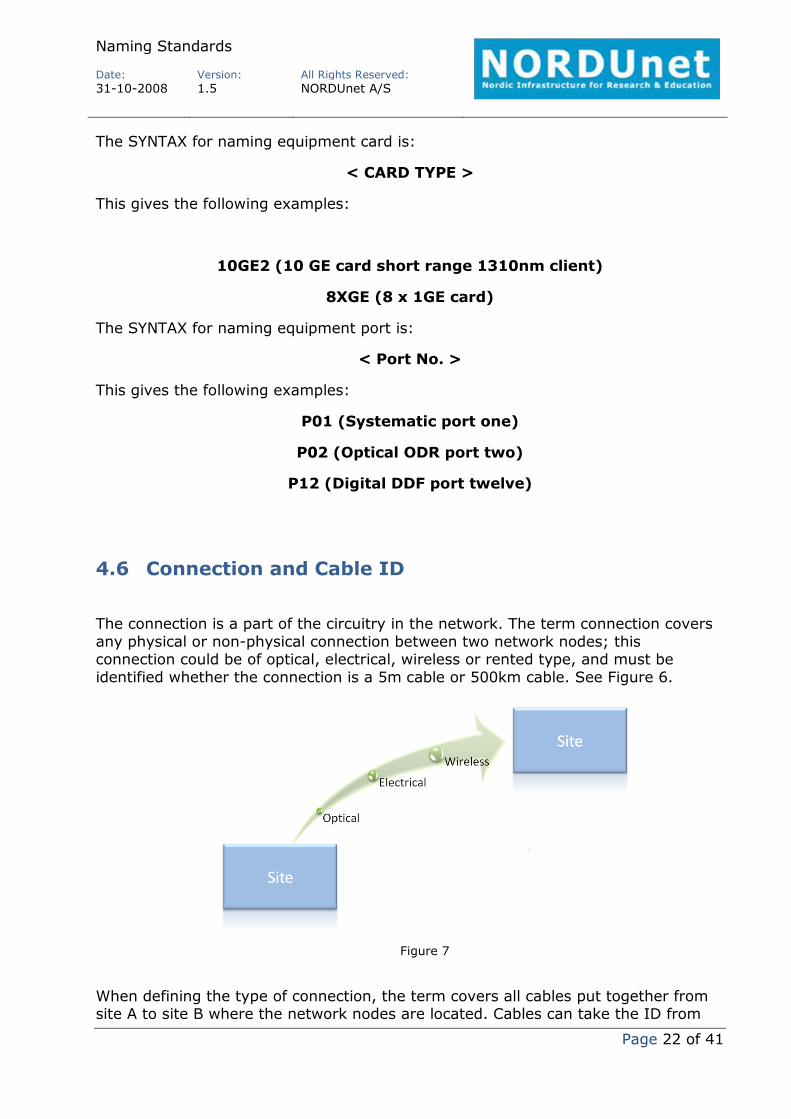
4.6 Connection and Cable ID
The connection is a part of the circuitry in the network. The term connection covers any physical or nonphysical connection between two network nodes; this connection could be of optical, electrical, wireless or rented type, and must be identified whether the connection is a 5m cable or 500km cable. See Figure 6.
When defining the type of connection, the term covers all cables put together from site A to site B where the network nodes are located. Cables can take the ID from
Figure 7
Naming Standards
Date:
Version:
All Rights Reserved:
31102008 1.5 NORDUnet A/S
Page 23 of 41
the cable provider of a rented cable, or use a naming syntax to give a cable it’s ID. Cables must be identifiable at both ends.
The best and most efficient way to identify a rented cable, is to maintain the name or ID given by the cable provider, e.g. from Telenor or Global Crossing.
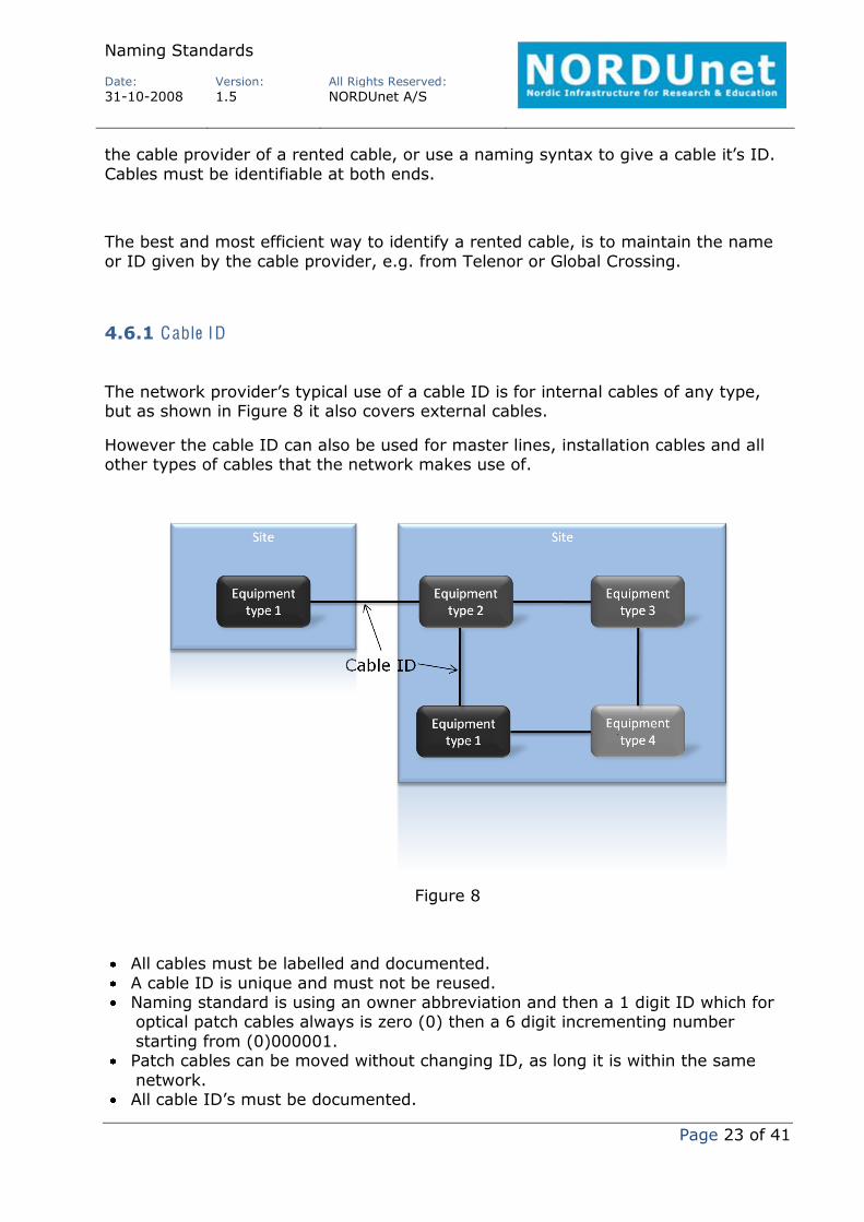
4.6.1 Cable ID
The network provider’s typical use of a cable ID is for internal cables of any type, but as shown in Figure 8 it also covers external cables.
However the cable ID can also be used for master lines, installation cables and all other types of cables that the network makes use of.
Figure 8
All cables must be labelled and documented. A cable ID is unique and must not be reused. Naming standard is using an owner abbreviation and then a 1 digit ID which for optical patch cables always is zero (0) then a 6 digit incrementing number starting from (0)000001.
Patch cables can be moved without changing ID, as long it is within the same network.
All cable ID’s must be documented.

Naming Standards
Date:
Version:
All Rights Reserved:
31102008 1.5 NORDUnet A/S
Page 24 of 41
4.6.2 Cable ID SY N T A X
The SYNTAX for naming cable is:
<< CABLE OWNER > < 1 digit ID >< 6 DIGIT RUNNING NUMBER >>
This gives the following examples:
(Please note that the first two ID’s are kept from the different providers of optical fibres)
1050001 (Telenor is the provider delivery number 105 section running number is 0001)
45031023 (Global Crossing is the provider provider given number, no explanation)
NU0000001 (NORDUnet patch cable 0000001)
SU0000001 (SUNET patch cable 0000001)
FU0000001 (FUNET patch cable 0000001)
4.6.3 How to make the cable ID unique
1. Always start a cable ID with an owner id. 2. Separate the owner id using a minus sign (). 3. Type 0 as an indication for cables 4. Add the next incrementing unique number. 5. Make sure that the naming is done in both ends of the cable and documented.
4.6.4 Tube and Duct ID
Tubes and ducts are normally named by the owner of the installations; however a naming convention can be followed in case the tubes and ducts are lacking this information.
Both tubes and duct must be labelled with a unique identifier.
All tubes and ducts must be labelled and documented.
Naming Standards
Date:
Version:
All Rights Reserved:
31102008 1.5 NORDUnet A/S
Page 25 of 41
A tube or duct ID is unique and must not be reused. Naming standard is using an owner abbreviation and then a 6 digit incrementing number starting from 000001.
Moved tubes and ducts must change ID. All tube and duct ID’s must be documented.
4.6.5 Tube and Duct ID SY N T A X
The SYNTAX for naming tube or duct is:
<<TUBE OWNER> <6 DIGIT RUNNING NUMBER>>
<<DUCT OWNER> <6 DIGIT RUNNING NUMBER>>
4.6.6 How to make the tube and duct ID unique
1. Check the documentation for last used running number for the network the tube or duct has to be created to.
2. Increment the running number one up. 3. Start a tube or duct ID with an owner id. 4. Separate the owner id using a minus sign (). 5. Type the incremented unique running number. 6. Make sure that the naming is done in both ends of the tube or duct and documented.

Naming Standards
Date:
Version:
All Rights Reserved:
31102008 1.5 NORDUnet A/S
Page 26 of 41
5 Logical naming standards
The following chapter explains the relations between services, circuits, paths and links, see Figure 9.
In order to establish synergy with the software of a NMS, some parts of the documentation is kept in the software only, which leaves the physical part and some of the logical part of the network to a network inventory and the full logical part of the network to the NMS software.
The common definitions of the logical parts are illustrated in Figure 9. A service typically covers transmission from A to Z, using three transmission options; circuits, paths and links, as well as cables. A circuit is made of one or more paths and can have same ending points as the service. A path is made of one or more links as well as cables. The text in table 5 shows the items that can be named within a network.
Commonly for all services and the three transmission types is that all uses a six digit running number with a one type identifier. The running number is incremented for each new service, circuit, path and link.
While looking at the customer end, the customer could have more than one service running over the same circuit; therefore this must be held accordingly to the customer in a separate document or table within a Network Inventory database.
Figure 9

Naming Standards
Date:
Version:
All Rights Reserved:
31102008 1.5 NORDUnet A/S
Page 27 of 41
The logical items that can be labelled are:
Item Explanation Reference chapter
Link Defines the connectivity between two equipments. Link uses physical patch cables or transport media on the physical level.
3.1
Path Is the logical connectivity between two endpoint equipments, using one or more links.
3.2
Circuit Is the endtoend connectivity for a service to a customer, using links and paths.
3.3
Service The service covers from the delivery of fibers to any organization, to paths, to circuits to participation in international services.
3.4
Table 5
Ultimately the customer could request a service spanning over many different networks, e.g. from UNINETT, to NORDUnet, to Surfnet, to Canarie and further on.
This setup could be within the GLIF network. See. Figure 10.
Figure 10
Naming Standards
Date:
Version:
All Rights Reserved:
31102008 1.5 NORDUnet A/S
Page 28 of 41
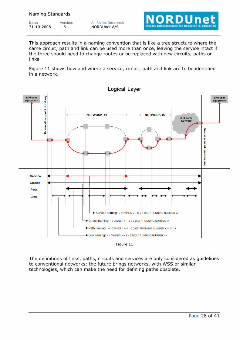
This approach results in a naming convention that is like a tree structure where the same circuit, path and link can be used more than once, leaving the service intact if the three should need to change routes or be replaced with new circuits, paths or links.
Figure 11 shows how and where a service, circuit, path and link are to be identified in a network.
The definitions of links, paths, circuits and services are only considered as guidelines to conventional networks; the future brings networks, with WSS or similar technologies, which can make the need for defining paths obsolete.
Figure 11

Naming Standards
Date:
Version:
All Rights Reserved:
31102008 1.5 NORDUnet A/S
Page 29 of 41
5.1 Link ID
The link is the physical and/or logical connection between two equipments. See Figure 12.
The link is the first physical and/or logical building block to the network, and part of the backbone network.
A link may be used multiple times by paths, circuits and services.
The link must always start with the identifying number 1 (according to section 3.1.1, table 2) followed by 6 running numbers to a total of 7 digits for the link ID.
Every link must be uniquely identified within the network. All link ID’s must be documented.
Figure 12

Naming Standards
Date:
Version:
All Rights Reserved:
31102008 1.5 NORDUnet A/S
Page 30 of 41
5.1.1 The link ID naming SY N T A X
The SYNTAX for naming link is:
<< LINK OWNER > – 1 < 6 DIGIT RUNNING NUMBER >>
This gives the following examples:
NU1000001 (NORDUnet Link 1)
NU1000002 (NORDUnet Link 2)
SU1000001 (SUNET Link 1)
5.1.2 How to make the link ID unique
1. Check the documentation for last used running number for the network the link has to be created to.
2. Increment the running number one up (last 6 digits). 3. Start with a network ID. 4. Separate the network ID using a minus sign (). 5. Type the identifier digit 1 for link. 6. Type the incremented unique running number (last 6 digits). 7. Update the documentation with the new link ID.
5.1.3 Examples of used link ID’s
Link ID results should look like this:
NU1000105: The network is NORDUnet, unique running number is 1000105 NU1000104: The network is NORDUnet, unique running number is 1000104 NU1999999: The network is NORDUnet, unique running number is 1999999

Naming Standards
Date:
Version:
All Rights Reserved:
31102008 1.5 NORDUnet A/S
Page 31 of 41
5.2 Path ID
The network path is an overlay on the links already created in the network. A path can be used for multiple services and circuits if necessary. See Figure 13.
A path is according to Figure 11 the network ending points and can serve as a component directly to a service skipping a circuit usage.
The path must always start with the identifying number 4 (according to section 3.1.1, table 2) followed by 6 running numbers to a total of 7 digits for the path ID.
Every path must be uniquely identified within the network. The unique path must have relations to all links used to build the path. All path ID’s must be documented.
Figure 13
5.2.1 The path ID naming SY N T A X
The SYNTAX for naming path is:
<< PATH OWNER > – 4 < 6 DIGIT RUNNING NUMBER >>
This gives the following examples:
NU4000001 (NORDUnet Path 1)

Naming Standards
Date:
Version:
All Rights Reserved:
31102008 1.5 NORDUnet A/S
Page 32 of 41
NU4000002 (NORDUnet Path 2)
SU4000001 (SUNET Path 1)
5.2.2 How to make the path ID unique
1. Check the documentation for last used running number for the network the path has to be created to.
2. Increment the running number one up (last 6 digits). 3. Start with a network ID. 4. Separate the network ID using a minus sign (). 5. Type the identifier digit 4 for path. 6. Type the incremented unique running number (last 6 digits). 7. Update the documentation with the new path ID.
5.2.3 Examples of used path ID’s
Path ID results should look like this:
NU4000005: The network is NORDUnet, the paths unique running number is 4000005, and the path is the working path.
NU4001104: The network is NORDUnet, the paths unique running number is 4001104, and the path is the working path.
NU4000308: The network is NORDUnet, the paths unique running number is 4000308, and the path is the working path.
Naming Standards
Date:
Version:
All Rights Reserved:
31102008 1.5 NORDUnet A/S
Page 33 of 41
5.3 Circuit ID
Circuits comes in many variations, but commonly for all is, that it must be using one or many paths in order to reach from A to Z.
The circuit is defined as something that can be controlled within the same network, e.g. in a provider network.
The circuit must always start with the identifying number 5 (according to section 3.1.1, table 2) followed by 6 running numbers to a total of 7 digits for the circuit ID.
Every circuit must be uniquely identified within the network. Every circuit must have relations to all paths it is using. Every circuit must have relations to which customer service it belongs to. Every circuit must be uniquely identified to delivering network. All circuit ID’s must be documented.
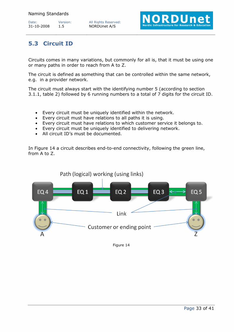
In Figure 14 a circuit describes endtoend connectivity, following the green line, from A to Z.
Figure 14
Naming Standards
Date:
Version:
All Rights Reserved:
31102008 1.5 NORDUnet A/S
Page 34 of 41
5.3.1 The ci rcuit ID naming SY N T A X
The SYNTAX for naming circuit is:
<< CIRCUIT OWNER > – 5 < 6 DIGIT RUNNING NUMBER >>
This gives the following examples:
NU5000001 (NORDUnet, Circuit 1)
NU5000002 (NORDUnet, Circuit 2)
SU5000001 (SUNET, Circuit 1)
5.3.2 How to make the ci rcuit ID unique
A short description how to use the naming syntax:
1. Check the documentation for last used running number for the network the circuit have to be created to.
2. Increment the running number 1. 3. Start with the network id. 4. Separate the network ID using a minus sign (). 5. Type the digit 5 for circuit. 6. Type the incremented unique running number (last 6 digits). 7. Update the documentation with the new circuit ID.
5.3.3 Examples of used ci rcuit ID’s
Circuit ID results should look like this:
NU5000005: The network is NORDUnet, the circuit’s unique running number is 5000005, and the circuit is the working circuit.
NU5001104: The network is NORDUnet, the circuit’s unique running number is 5001104, and the circuit is the working circuit.
NU5000308: The network is NORDUnet, the circuit’s unique running number is 5000308, and the circuit is the working circuit.

Naming Standards
Date:
Version:
All Rights Reserved:
31102008 1.5 NORDUnet A/S
Page 35 of 41
5.4 Service ID
The service is derived from Figure 15, as a result of the naming standards as a whole. The service covers renting out a rack space, to cables, to equipment to transmission from A to Z. Please note that Figure 15 only illustrates the relations for the logical transmission and cables (connection, see section 4.6).
The service, presuming it is logical, is overlaying circuits, paths and links. The same service number can overlay or cover many circuits, paths, links and physical elements, such as power and patch cables. The relations to all these individual elements are easily handled within a Network Inventory system, they can however also be handled in any document system.
The service must always start with the identifying letter S (according to section 3.1.1, table 2) followed by 6 running numbers to a total of 7 digits for the service ID.
Every service must be uniquely identified to a specific organization/contact. The unique service must have relations to all circuits, paths, links and so forth, which build the service.
All service ID’s must be documented.
5.4.1 The service ID naming SY N T A X
The SYNTAX for naming a service is:
<< SERVICE OWNER > – S < 6 DIGIT RUNNING NUMBER >>
Figure 15

Naming Standards
Date:
Version:
All Rights Reserved:
31102008 1.5 NORDUnet A/S
Page 36 of 41
This gives the following examples:
NUS000001 (NORDUnet Service 1)
NUS000002 (NORDUnet Service 2)
SUS000001 (SUNET Service 1)
5.4.2 How to make the service ID unique
1. Check the documentation for last used running number for the network the service has to be created to.
2. Increment the running number one up (last 6 digits). 3. Start with a network ID. 4. Separate the network ID using a minus sign (). 5. Type the letter S for service. 6. Type the incremented unique running number (last 6 digits). 7. Update the documentation with the new service ID.
5.4.3 Examples of used service ID’s
Service ID results should look like this:
NUS000005: The network is NORDUnet, the services unique running number is S000005.
NUS001104: The network is NORDUnet, the services unique running number is S001104.
NUS000308: The network is NORDUnet, the services unique running number is S000308.
5.5 Logical summary
Returning to Figure 11 in the beginning of this chapter a summary of how to document a service should end up in any documenting system is explained here.

Naming Standards
Date:
Version:
All Rights Reserved:
31102008 1.5 NORDUnet A/S
Page 37 of 41
Notice NUS000001 is using a circuit; NU5000001, this circuit might in other cases be replaced by the usage of paths and links alone.
NU5000001 is the only circuit for the service, in other cases the use of a circuit could obsolete depending on the service.
The circuit has 3 underlying paths, and 2 links. Notice the last 2 links are not related to the paths used.
Each path has 1 to 4 links in use.
What is not covered in Figure 16 is the use of patch cables of either electrical or optical type, granted it could be expanded to also cover this; it is not the intention with this summary.
For each path shown in Figure 11, there might be several NMS systems, or at least one per network.
This could be the same with the circuit, but not likely, remember Figure 11 is an example using
generality for the naming standard, which might not always be the only truth in real life situations.
The naming standard is generically build, meaning that for each equipment branch, IP, Ethernet, Optical and so forth a explanatory appendix must be written, making the mapping from the standards to what should be understood when looking at this particular equipment and it’s links, paths and circuits.
Figure 15
Naming Standards
Date:
Version:
All Rights Reserved:
31102008 1.5 NORDUnet A/S
Page 38 of 41
6 Linking logical naming standards to organizations
As services covers the delivery of a cables, links, paths and circuits, the need to bind the naming to provider or customer.
The organization covers customer and provider, as well as any partners in the future. The organization can also be a project, as the international radio astronomy project.
Within each organization there is x amount of contacts. Depending on the contacts relationship to organizations he or she can appear as contact to services spanning many organizations.
In short, a service has relation to an organization which again has relation to a contact.
6.1 Organization
There is no standard for naming organization, except the name must be short and precise. Any other information to the organization must be described in the organization attributes. The organization can be all of the below stated:
Project name Customer name Provider name Partner name
6.1.1 The organization naming SY N T A X
The SYNTAX for naming an organization is:
< ORGANIZATION name >
This gives the following examples:
GLORIAD (GLORIAD, project)

Naming Standards
Date:
Version:
All Rights Reserved:
31102008 1.5 NORDUnet A/S
Page 39 of 41
SUNET (SUNET, customer)
SURFnet (SURFnet, partner)
6.2 Contact
The contact naming standard is to use the contacts full name.
The contact name will probably not be unique in some cases, but the relation and attributes for the contact make the contact unique.
6.2.1 The contact naming SY N T A X
The SYNTAX for naming a contact is:
<< FIRST name > < LAST name >>
This gives the following examples:
Heino Radmer (Heino Radmer)
Lars Lange Bjørn (Lars Lange Bjørn)
Stefan Liström (Stefan Liström)
Naming Standards
Date:
Version:
All Rights Reserved:
31102008 1.5 NORDUnet A/S
Page 40 of 41
7 Documentation
It is very critical that the Naming Standard is being followed, only by doing that will ensure that a documenting system will work, also in practice. By following a naming standard, searching for information and running scripts and so forth, is also ensured to run without complications. Furthermore, integrations with other automatic systems have a better chance to succeed.
It is strongly emphasized to implement and use a dedicated Network Inventory system. A specific system should not be dictated, but a throughout investigation of a suitable system should be conducted well in advance.
If there is no Network Inventory System available upon the implementation of the naming standard to the live network, a simple excel sheet type of static document is advisable. This will ensure a quick transition to a database driven Inventory System, since all data within the sheet can be converted to CVS data. The back draw by doing so is the layout of the sheet type could be unreadable to common people not used to work with databases.
If a Network Inventory system is not in place, the documentation must be done by a dedicated staff only.
More help with creating a excel sheet type document can be requested to NORDUnet.
Naming Standards
Date:
Version:
All Rights Reserved:
31102008 1.5 NORDUnet A/S
Page 41 of 41
8 Abbreviations
DDF Digital Distribution Frame
FSKnet Forskningsnettet
FUNET Finnish University Network
ID Identifier as specified by the NREN
MGNT Management
NI Network Inventory
NMS Network Management System
NORDUnet Nordic University Network
NREN
ODF
National Research and Educational Network
Optical Distribution Frame
ODR Optical Distribution Rack
RM/BM Management software
SUNET Sweden University Network
UNINETT University Network Norway


![[MatErial codE standards] - BRELECT · [MatErial codE standards] Material codes and names and their respective naming rules are managed in accordance with the prescribed standards.](https://static.documents.pub/doc/80x56/5bfa875b09d3f24c058c838f/material-code-standards-material-code-standards-material-codes-and-names.jpg)


