Nanocatalyst Superior to Pt for Oxygen Reduction Reactions: TheCase of Core/Shell Ag(Au)/CuPd NanoparticlesShaojun Guo,†,∥ Xu Zhang,‡ Wenlei Zhu,† Kai He,§ Dong Su,§ Adriana Mendoza-Garcia,† Sally Fae Ho,†
Gang Lu,*,‡ and Shouheng Sun*,†
†Department of Chemistry, Brown University, Providence, Rhode Island 02912, United States‡Department of Physics and Astronomy, California State University, Northridge, California 91330, United States§Center for Functional Nanomaterials, Brookhaven National Laboratory, Upton, New York 11973, United States
*S Supporting Information
ABSTRACT: Controlling the electronic structure and surface strain of ananoparticle catalyst has become an important strategy to tune and tooptimize its catalytic efficiency for a chemical reaction. Using densityfunctional theory (DFT) calculations, we predicted that core/shell M/CuPd (M = Ag, Au) NPs with a 0.8 or 1.2 nm CuPd2 shell have similar butoptimal surface strain and composition and may surpass Pt in catalyzingoxygen reduction reactions. We synthesized monodisperse M/CuPd NPsby the coreduction of palladium acetylacetonate and copper acetylaceto-nate in the presence of Ag (or Au) nanoparticles with controlled shellthicknesses of 0.4, 0.75, and 1.1 nm and CuPd compositions and evaluatedtheir catalysis for the oxygen reduction reaction in 0.1 M KOH solution. Aspredicted, our Ag/Cu37Pd63 and Au/Cu40Pd60 catalysts with 0.75 and 1.1 nm shells were more efficient catalysts than thecommercial Pt catalyst (Fuel Cells Store), with their mass activity reaching 0.20 A/mg of noble metal at −0.1 V vs Ag/AgCl (4 MKCl); this was over 3 times higher than that (0.06 A/mg Pt) from the commercial Pt. These Ag(Au)/CuPd nanoparticles arepromising non-Pt catalysts for oxygen reduction reactions.
■ INTRODUCTION
Recent advances in energy research call for the rational designand synthesis of catalysts with unprecedented efficiency incatalyzing energy conversion reactions,1−4 especially the oxygenreduction reaction (ORR).5−8 Numerous studies on ORR havefocused on catalysts with ultralow Pt contents, with bothelectronic and geometric effects being used to explain ORRcatalysis. Electronic effects result in charge redistribution on thesurface of the catalysts, making the catalytic sites “hotter”,9−13
while geometric effects often put shape and atom distance inconsideration to tune the binding strength between Pt andO.14−16 Pt−O bonding on a perfect Pt(111) is calculated to be0.2 eV stronger than the optimal level (ΔE = −0.2 eV),17,18 anda compressed Pt strain on the catalyst surface may help toweaken the Pt−O bond and to enhance ORR catalysis.13−16
Experimentally, a variety of Pt-based alloy and core/shellnanoparticles (NPs) have been designed, synthesized, andtested to improve oxygen dissociative adsorption on Pt and Pt−O desorption for Pt surface regeneration.19−32 A moreimportant aspect is to develop a non-Pt catalyst with catalyticpower comparable to or even superior to that of Pt.33,34 Studieson energetics of oxygen dissociative adsorption on 1 nm Pdshells with a series of core metals have shown that tuningcharge redistribution and surface strain can change the d-bandcenter of the Pd shell and, thus, oxygen dissociative adsorptionenergy. For this reason, core/shell Cu/Pd, Co/Pd, and Mo/Pd
systems may be similar to Pt in catalyzing ORRs.35 In contrast,the presence of a more electronegative Au core does not favorthe increase in Pt activity for the ORR, but the Au core can helpto enhance shell stability.28
Considering Au (or Ag) core and Cu alloy effects on PdORR catalysis,35 we chose to study a ternary system based oncore/shell Ag/CuPd or Au/CuPd NPs to understand how theAg (or Au) core and CuPd alloy effects can be used to tune andoptimize Pd catalysis for the ORR. Herein, we present ourstudy on tuning M/CuPd (M = Ag, Au) into the active ORRcatalyst in 0.1 M KOH solution. The unique aspect of theternary core/shell M/CuPd for ORR is that it allows the dualtuning of both surface strain and composition to achieve morerational control on catalytic properties and to facilitate catalysisoptimization. Our computational and experimental data bothshow that CuPd alloy composition and shell thickness areimportant to control the ORR activity of the Ag/CuPd NPs.The optimal Cu concentration and CuPd shell thickness are37(±3)% and ∼1 nm, respectively. Au as a core in the core/shell structure can further improve CuPd catalysis for the ORR.Among the different catalysts studied, including Ag, CuPd, Ag/CuPd, and Au/CuPd as well as commercial Pt, Ag/CuPd andAu/CuPd core/shell NPs under the optimal tuning show the
Received: August 12, 2014Published: October 3, 2014
highest mass activity for the ORR at 0.18 and 0.20 A/mg ofnoble metal, respectively, at −0.1 V (vs Ag/AgCl) and retain77.6% of this activity after 48000 s i−t test. As a comparison,the commercial Pt catalyst (Fuel Cells Store) has a mass activityof 0.06 A/mg of Pt and retains 62.9% activity after the samestability test. Our studies demonstrate an important route tothe rational design and synthesis of highly active non-Ptcatalysts for the ORR.
■ EXPERIMENTAL METHODS ANDCOMPUTATIONAL MODELS
Chemicals and Materials. Oleylamine (OAm, >70%), 1-octadecene (ODE), oleic acid (OA), palladium acetylacetonate(Pd(acac)2), copper acetylacetonate (Cu(acac)2), HAuCl4·H2O, silvernitrate, 1,2-tetradodecanediol, hexane, isopropyl alcohol, ethanol, andNafion (5%) were all purchased from Sigma-Aldrich. The C−Pt (20%mass loading, mainly 2.5−3.5 nm in diameter) catalyst was obtainedfrom Fuel Cell Store.Instrumentation. Transmission electron microscopy (TEM)
images were obtained with a Philips CM 20 instrument operating at200 kV. Scanning transmission electron microscopy (STEM) analyseswere carried out using a Hitachi HD2700C (200 kV) with a probeaberration corrector, at the Center for Functional Nanomaterials atBrookhaven National Laboratory. The 2D electron energy-lossspectroscopy (EELS) mapping was collected using a high-resolutionGatan-Enfina ER instrument with a probe size of 1.3 Å. A power lawfunction was used for EELS background subtraction. X-ray diffraction(XRD) characterization was carried out on a Bruker AXS D8-Advanced diffractometer with Cu Kα radiation (λ =1.5418 Å). Theinductively coupled plasma-atomic emission spectroscopy (ICP-AES)measurements were carried on a JY2000 Ultrace ICP Atomic EmissionSpectrometer equipped with a JY AS 421 autosampler and 2400g/mmholographic grating. Samples for TEM analysis were prepared bydepositing a single drop of diluted nanoparticle dispersion in hexaneon amorphous carbon coated copper grids. The electrochemicalmeasurements on a glassy-carbon (GC) electrode using Ag/AgCl (vs 4M KCl) as the reference electrode and platinum wire as the counterelectrode, respectively, were performed on a potentiostat (Autolab302N).Synthesis of 3.1 nm Ag and Au NP. A 0.38 g portion of AgNO3
was mixed with 20 mL of OAm and 0.4 mL of OA, and themagnetically stirred mixture was heated to 120 °C for 18 h. Thesolution was then cooled to room temperature. A 30 mL portion ofacetone was added to precipitate the product. The product wasseparated by centrifugation at 9000 rpm for 10 min, washed withethanol, and redispersed in hexane.Au NPs with different sizes were synthesized according to the
reported protocols.36
Synthesis of Ag/CuPd NPs. In a typical synthesis of Ag/Cu37Pd63NPs, 30 mg of Pd(acac)2 and 26 mg of Cu(acac)2 were mixed with 10mL of ODE, 1.0 mL of OAm, 1.0 mL of OA, and 0.2 g of 1,2-tetradodecanediol. The magnetically stirred solution was then heatedto 80 °C under N2 protection. A 30 mg portion of Ag seeds dispersedin 2 mL of ODE was rapidly injected into the above solution, whichwas further heated to 200 °C at a heating rate of 4−5 °C/min. Thesolution was heated to 200 °C for 25 min and cooled to roomtemperature. Isopropyl alcohol was added to precipitate the product.The product was separated by centrifugation at 9000 rpm for 10 min,washed once with isopropyl alcohol and then ethanol, and redispersedin hexane.Similarly, replacing Ag NPs with 40 mg of Au NPs gave Au/CuPd
NPs.Synthesis of 3.5 nm Cu40Pd60 NPs. Cu40Pd60 NPs (3.5 nm) were
synthesized according to the reported protocols.37 In a typicalsynthesis, 0.30 mmol of Cu(acac)2 and 0.30 mmol of Pd(acac)2were dissolved in 3 mL of OAm. This solution was then injected into amixture of morpholine−borane (1.5 mmol), 3 mL of OAm, and 7 mLof ODE at 80 °C. The resulting mixture was subsequently heated to
100 °C and kept at that temperature for 1 h. Finally, the NPs werewashed in a mixture of acetone and isopropyl alcohol and centrifugedtwo times at 9000 rpm for 10 min before redispersing them in hexane.
NP Catalyst Preparation. A 20 mg portion of NPs dispersed in 20mL of hexane and 40 mg of Ketjen carbon dispersed in 30 mL ofhexane were mixed and further sonicated with a Fisher Scientific FS110 instrument for 1 h to prepare C-NPs. The product was separatedby centrifugation, washed twice with hexane, dried under ambientconditions, and further heated in the air at 150 °C overnight to removethe surfactant. The heat-treated C-NPs were redispersed in a mixturecontaining water, isopropyl alcohol, and Nafion (5%) (4/1/0.05 v/v/v) to form a 4 mg/mL suspension.
Electrochemistry. Prior to the surface coating, the GC electrode(5 mm in diameter) was polished with 1.0 and 0.05 μm aluminapowders, respectively, and rinsed with deionized water, followed bysuccessive sonications in ethanol and doubly distilled water. Theelectrode was allowed to dry under nitrogen. A 5 μL portion of catalystink was cast on the GC electrode and dried. The counter electrode wasPt wire, and the reference electrode was Ag/AgCl (4 M KCl). Theelectrolyte was N2-saturated 0.1 M KOH solution. All of the catalystelectrodes were cleaned with a steady-state CV in the range of −0.8 to+0.1 V (vs Ag/AgCl) at 100 mV/s for 20 cycles. ORR measurementswere conducted in O2-saturated 0.1 M KOH solution. The diskrotation rate was set at 1600 or 400 rpm. The potential scan rate wasat 10 mV/s.
Calculations of ΔEO on Intermetallic CuPd Surface. The EOvalue was determined by placing an O atom on the fcc hollow sitefollowing
= + − −E E E E[PdCu O] [PdCu] [O ]/2O 2
where E[PdCu+O] and E[PdCu] are total energies of the PdCu alloysurface with and without O adsorbate, respectively. E[O2] is the totalenergy of a oxygen molecule. For DFT calculations of total energies,we used 3 × 3 (√3 × √3)R30° surface unit cells. A four-layer slabwas used for these calculations with the top two layers fully relaxed.The optimal EO value is 0.2 eV higher than that on a Pt(111) flatsurface.17,18 The ΔEO value was then calculated by shifting EO relativeto this optimal value.
Calculation of Surface Strain on Core/Shell NPs. We constructthe cuboctahedral models to represent core/shell NPs as shown inFigure 1b,d. To model the random alloy shell, 10 randomly generatedatomic structures were examined to provide the strain distribution. Allatoms were fully relaxed by the embedded atom method (EAM)interatomic potentials.38 There are eight (111) facets in thecuboctahedral NP, and for each (111) facet we selected three O-adsorbed sites ( fcc hollow sites) to measure the local strain. Thus, foreach NP model, 240 sites were included in the strain distribution.
Calculation of Interfacial Energy. Two 4 × 2 slabs with fouratomic layers were used to calculate the interfacial energy (Figure 1f),with the bottom two layers being the core material M (M = Au, Ag).The left part of Figure 1f corresponds to the Pd|Cu|M interface andthe right part to the Cu|Pd|M interface. The interfacial energydifference is defined as
Δ = | | − | |E E E[M] [Pd Cu M] [Cu Pd M]
where E[Pd|Cu|M] and E[Cu|Pd|M] are the total energies of the Pd|Cu|M and Cu|Pd|M interfaces, respectively.
Computational Parameters. The DFT calculations were carriedout using the VASP package39,40 with the projector augmented wavepseudopotentials (PAW)41 and Perdew−Burke−Ernzerhof generalizedgradient approximation (PBE-GGA).42 An energy cutoff of 400 eV wasused for the plane-wave basis set. The Brillouin zone was sampled onthe basis of the Monkhorst−Pack scheme with a 3 × 3 × 1 k-pointmesh.43
■ RESULTS AND DISCUSSIONComputational Studies of M/CuPd NPs. To understand
the effects of alloy composition, shell thickness, and corematerial of M/CuPd NPs on Pd−O bonding and further on the
Journal of the American Chemical Society Article
dx.doi.org/10.1021/ja508256g | J. Am. Chem. Soc. 2014, 136, 15026−1503315027
ORR activity, we employed density functional theory (DFT) toanalyze the oxygen adsorption energy (EO), a commonly useddescriptor for ORR activity, on different kinds of NPsurfaces.17,18 Since oxygen overbinds to Pd and Cu surfaces(ΔEO is negative), the goal is to design CuPd alloys with lessnegative ΔEO values to achieve higher ORR activities. First, wefocus on the dependence of ΔEO on the surface strain andchemical composition of intermetallic CuPd (the disorderedCuPd alloys have similar dependence; see Figure S1(Supporting Information). Specifically, three chemical compo-sitions with Cu/Pd atomic ratios of 2/7, 1/2, and 2/1, eachunder a compression from 0 to 5%, were examined. Figure 1adepicts ΔEO as a function of the surface strain and chemicalcomposition on the flat (111) surface of the CuPd alloys. Wesee a monotonic increase of ΔEO with respect to thecompression of the alloys. Since Cu has a smaller latticeconstant than Pd, alloying more Cu would increase thecompression and ΔEO value. However, a large Cu concen-tration (green curves in Figure 1a) actually lowers ΔEO, whichis consistent with the fact that oxygen binds too strongly on theCu surface. Hence, there is a competition between the strainand chemical effects with respect to Cu concentration.Three cuboctahedral NP models are constructed to represent
Ag/CuxPdy with x/y = 2/7, 1/2, and 2/1, and these core/shellNPs have the same core diameter of 3.2 nm (16 atomic layers)and shell thickness of 0.8 nm (4 atomic layers) (Figure 1b). AllCuPd alloy shells are set to have a solid solution structure toestimate the strain distribution on the shells. As shown inFigure 1c, the higher the Cu concentration in the alloy, thegreater the compressive strain on the NP surface. On the basisof the strain distributions and the alloy compositions, weestimated the ΔEO distribution for each NP as indicated by the
dashed boxes in Figure 1a. The horizontal and vertical positionsof each box represent the range of the strain and ΔEO
distribution for each NP, respectively. The ORR activity ofthe core/shell NPs is ranked as Ag/CuPd2 > Ag/Cu2Pd7 > Ag/Cu2Pd and the optimized Ag/CuPd NPs even surpass Pt forthe ORR.We chose Ag/CuPd2 NPs to study the shell thickness effect
on the ORR. Three different core/shell NPs with shellthicknesses of 0.4, 0.8, and 1.2 nm were examined, and theirstructures and surface strain distributions are shown in Figure1d,e. We can see that the shell becomes more compressive asthe thickness increases. The Ag/CuPd2 NPs with 0.8 and 1.2nm shell thicknesses show the strain distributions similar to butbetter than those with 0.4 nm shells for the ORR. Since theNPs have the same chemical composition and only the straineffect is at play, we conclude that for Ag/CuPd2, either a 0.8 ora 1.2 nm CuPd shell would have a higher ORR activity.To study the core effect on CuPd shell strain, we replaced Ag
with Au and calculated the surface strain distribution (Figure1c). We can see that surface strain distributions areindependent of the core materials. We calculated the interfacialenergy between the PdCu shell and the core (Au or Ag). Forsimplicity, we modeled the shell by a bilayer Pd|Cu (Pd on topof Cu) vs Cu|Pd (Cu on top of Pd) (Figure 1f). When the coreis Au, the Pd|Cu|Au interface is energetically more stable thanthe Cu|Pd|Au interface with an energy difference of −264 mJ/m2. If the core is Ag, the Pd|Cu|Ag interface is energetically lessstable than the Cu|Pd|Ag interface with an energy difference of+5 mJ/m2. Therefore, with Au as the core, it is energeticallyfavorable for Pd to segregate at the NP surface, leading tohigher ORR activity.
Figure 1. (a) ΔEO as a function of strain and composition. Black, red, and green curves represent Cu/Pd atomic ratios of 2/7, 1/2, and 2/1,respectively. Several curves in each color correspond to various fcc hollow sites for O adsorption. ΔEO on the Pt(111) surface is indicated by thedashed horizontal line. Black, red, and green boxes outline the possible ΔEO values on Ag/Cu2Pd7, Ag/CuPd2, and Ag/Cu2Pd NPs, respectively. (b,c) Models of core/shell NPs for various shell compositions with a shell thickness of 0.8 nm (b) and evaluated distribution of surface strain on thesecore/shell NPs (c). The dashed curve in (c) indicates Au/CuPd2 NPs. (d, e) Models of core/shell NPs for various shell thickness with a compositionof CuPd2 (d) and evaluated distribution of surface strain on these core/shell NPs (e). (f) Slab models for calculation of Pd|Cu|M (left) and Cu|Pd|M(right) interfacial energies.
Journal of the American Chemical Society Article
dx.doi.org/10.1021/ja508256g | J. Am. Chem. Soc. 2014, 136, 15026−1503315028
Synthesis of M/CuPd NPs. Our computational resultsindicate that Ag/CuPd2 NPs with 0.8 and 1.2 nm shellthicknesses may surpass Pt on catalysis for the ORR andreplacing Ag with Au can further optimize the ORR catalysis.To confirm these predictions, we developed a seed-mediatedgrowth method to prepare monodipserse core/shell M/CuPdNPs for electrocatalytic studies of ORR. In the synthesis of Ag-based core/shell NPs, we first prepared monodisperse Ag NPsby reacting 380 mg of silver nitrate with 20 mL of OAm in thepresence of 0.4 mL of OA at 120 °C for 18 h (see ExperimentalMethods and Computational Models). Figure 2a shows thetypical TEM image of the Ag NPs. The Ag NPs have an averagesize of 3.1 ± 0.2 nm. To synthesize Ag/CuPd NPs, 30 mg ofPd(acac)2 and 26 mg of Cu(acac)2 were added to a solution of10 mL of ODE, 1.0 mL of OAm, 1.0 mL of OA, and 0.2 g of1,2-tetradodecanediol, and the solution was heated to 80 °C. A30 mg portion of Ag seeds dispersed in 2 mL of ODE wasadded to the above mixture, and the solution was further heatedto 200 °C for 25 min. The product was precipitated out byadding isopropyl alcohol and washed with isopropyl alcoholand ethanol, respectively, before it was dispersed in hexane.Inductively coupled plasma-atomic emission spectroscopy(ICP-AES) was used to measure the composition of the as-prepared Ag/CuPd NPs. The synthesis yielded Ag/Cu37Pd63with a 0.75 ± 0.05 nm shell, denoted as Ag/Cu37Pd63-0.75(Figure 2b). With the amount of Ag NPs and Pd(acac)2 fixed,the composition of the CuPd shell could be tuned bycontrolling the molar ratio of Pd(acac)2 to Cu(acac)2. Underthe same reaction conditions as in the synthesis of Ag/Cu37Pd63NPs, 30 mg of Pd(acac)2 + 13 mg of Cu(acac)2, and 30 mg ofPd(acac)2 + 52 mg of Cu(acac)2 resulted in Ag/Cu20Pd80(Figure S2a, Supporting Information) and Ag/Cu55Pd45(Figure S2b, Supporting Information), respectively. Further-more, with the amount of Ag NPs and the molar ratio ofPd(acac)2 to Cu(acac)2 fixed, the shell thickness of CuPd couldbe tuned from 0.4 ± 0.05 nm (denoted as Ag/Cu37Pd63-0.4;
Figure S3a, Supporting Information) to 1.1 ± 0.10 nm(denoted as Ag/Cu37Pd63-1.1; Figure S3b, SupportingInformation) when 15 mg of Pd(acac)2 and 13 mg ofCu(acac)2 and when 60 mg of Pd(acac)2 and 52 mg ofCu(acac)2 were added, respectively. Similarly, when 3.1 nm Au(Figure S4a, Supporting Information) or 5 nm Au NPs (FigureS4b, Supporting Information) (see Experimental Methods andComputational Models) were used as seeding NPs, 4.6 ± 0.3nm Au/CuPd (Figure 2c) or 7.0 ± 0.4 nm Au/CuPd NPs(Figure S4c, Supporting Information) with a 0.8 ± 0.05 nmshell were also prepared.Figure S5 (Supporting Information) shows the XRD patterns
of the face-centered cubic ( fcc) Ag, Ag/Cu20Pd80, Ag/Cu37Pd63,and Cu40Pd60 NPs. The diffraction peaks from the Ag/CuPdcore/shell NPs are between those from Ag and CuPd NPs,indicating that the formation of the core/shell structure leads tothe expansion of CuPd lattice spacing.44 High-resolution TEM(HRTEM) was used to analyze the detailed structure of a singleAg/CuPd NP, as shown in Figure 2d. The CuPd lattice fringeshave a 0.224 nm spacing, close to {111} interplanar distance offcc-CuPd (0.223 nm) but shorter than that of fcc-Ag (0.238nm). The elemental distribution within the core/shell structurewas characterized by aberration-corrected STEM-EELS (Figure2e,f), showing that NPs contain Pd in the outside shell and Ag(or Au) in the core. It should be noted that, from the CuPd andCuAg phase diagram (Figure S6, Supporting Information), Cuforms an alloy much easier with Pd than with Ag. Therefore, Cuwould stay in the shell of Ag/CuPd core/shell NPs but itcannot be detected easily by STEM-EELS in the thin CuPdshell.
Electrocatalysis of M/CuPd NPs. The electrocatalyticperformance of the as-synthesized M/CuPd NPs were studiedby cyclic voltammetry, the rotating disk electrode technique,and the current (i)−time (t) technique.45 To perform thesetests, the as-prepared NPs were first deposited on the Ketjencarbon support (EC-300J) via sonicating two constituents (the
Figure 2. (a−c) TEM and (d) HRTEM images of (a) Ag, (b, d) Ag/Cu37Pd63, and (c) Au/Cu40Pd60. (e, f) STEM-EELS mapping (29 × 66 pixels,spatial resolution of 3 Å) images of (e) 4.6 nm Ag/Cu37Pd63 and (f) 4.6 nm Au/Cu40Pd60 NPs.
Journal of the American Chemical Society Article
dx.doi.org/10.1021/ja508256g | J. Am. Chem. Soc. 2014, 136, 15026−1503315029
Figure 3. (a, b) Mass activity comparison at −0.2 V of Ag/CuPd NPs with different shell composition (a) and thickness (b) in O2-saturated 0.1 MKOH solution at a scan rate of 10 mV/s. Rotation rate: 1600 rpm. (c) ORR polarization curves of Ag/Cu37Pd63 NPs at different rotation rates; (d)K-L plots of the ORR from Ag/Cu37Pd63 NPs. (e, f) ORR polarization curves (e) and ORR mass activity summaries (f) at −0.1 V of Ag/Cu37Pd63,Cu40Pd60, and Ag NPs in O2-saturated 0.1 M KOH solution at 293 K. Scan rate: 10 mV/s. Rotation rate: 1600 rpm.
Figure 4. (a, b) ORR polarization curves (a) and ORR mass activity summaries (b) at −0.1 V of Ag/Cu37Pd63 and Au/Cu40Pd60 in O2-saturated 0.1M KOH solution at 293 K. Scan rate: 10 mV/s. Rotation rate: 1600 rpm. (c) ORR polarization curves of Au/Cu40Pd60 NPs at different rotationrates. (d) K-L plots of the ORR from Au/Cu40Pd60 NPs.
Journal of the American Chemical Society Article
dx.doi.org/10.1021/ja508256g | J. Am. Chem. Soc. 2014, 136, 15026−1503315030
mass ratio of NP to C is 1/2) in hexane46,47 and then heated to150 °C overnight to remove the surfactant according to theprevious method.28 These M/CuPd NPs were uniformlydistributed on a carbon support, as shown in Figure S7(Supporting Information) (denoted as C-M/CuPd). Thetreated C-NP catalysts were redispersed in deionized water/isopropyl alcohol/5% Nafion (4/1/0.05 v/v/v) to reach aconcentration of 4 mg/mL. A 5 μL portion of the catalyst inkwas casted on the surface of the GC electrode and dried underambient conditions. Figure S8a (Supporting Information) andFigure 3a show typical ORR polarization curves (Figure S8a)and mass activity comparisons (Figure 3a) of the Ag/CuPdNPs with different shell compositions obtained at roomtemperature in O2-saturated 0.1 M KOH. From Figure 3a,we can see that Ag/Cu37Pd63 NPs have the highest ORRactivity among all Ag/CuPd NPs studied. The effect of the shellthickness of CuPd on the ORR activity of Ag/CuPd NPs wasalso investigated, as shown in Figure S8b (SupportingInformation) and Figure 3b. The NPs with 0.75 nm shellshave ORR activities similar to those with ∼1.1 nm shell butactivities higher than those with 0.4 nm shells, which isconsistent with our computational prediction.Rotating disk electrode (RDE) measurements were used to
study the ORR kinetics of the Ag/Cu37Pd63 NPs in 0.1 M KOH(Figure 3c). The number of electrons involved in the reductionof one O2 molecule on the Ag/Cu37Pd63 NPs was determinedvia a combination of RDE techniques and the Koutecky−Levich (K-L) equation.48 The corresponding K-L plots (Figure3d) show the inverse current density (j−1) as a function of theinverse of the square root of the rotation speed (w−1/2) atdifferent potential values. The number of electrons wasdetermined to be about 4, indicating that the ORR on theAg/CuPd NPs is a 4e process, similar to that on thecommercial Pt catalyst measured in the same 0.1 M KOHsolution.48
Figure 3e shows typical ORR polarization curves of Ag/Cu37Pd63, CuPd, and Ag NPs in O2-saturated 0.1 M KOH.Both Ag NPs and Cu40Pd60 alloy NPs are less active than theAg/Cu37Pd63 NPs for the ORR. After normalization of theactivity against the amount of noble metals, the Ag/Cu37Pd63NPs have a 5.2 times higher catalytic activity for ORR than theCu40Pd60 NPs (Figure 3f). A comparison of the activity fromAg/Cu37Pd63, Cu40Pd60, and Ag NPs indicates that the core/shell NPs indeed show the synergistic core/shell effect onenhancing ORR catalytic activity.According to the prediction that Au as the core material can
further enhance CuPd ORR activity, we studied 4.6 nm Au/Cu40Pd60 NPs (0.8 nm CuPd shell) and compared their ORRactivity with that of Ag/Cu37Pd63 NPs (0.75 nm CuPd shell)(Figure 4). The ORR performance of the CuPd shell is indeedenhanced by changing the core from Ag to Au (Figure 4a).When they were normalized against all noble metals in thecore/shell structure, the mass activities of the Au/Cu40Pd60 NPsand Ag/Cu37Pd63 NPs obtained at a rotation of 1600 rpm havesimilar values (Figure 4b), but when only Pd is weighed in, theAu/CuPd NPs show a much higher mass activity (0.43 A/mgof Pd) than the Ag/CuPd NPs (0.16 A/mg of Pd) (Figure 4b).The ORR kinetics on the Au/Cu40Pd60 NPs was also analyzed,as shown in Figure 4c. The corresponding K-L plots (Figure4d) give n = 4.0 from −0.2 to −0.4 V, revealing that the Au/Cu40Pd60 NPs still favor a 4e oxygen reduction process.The ORR catalytic activity of the optimized Ag(Au)/CuPd
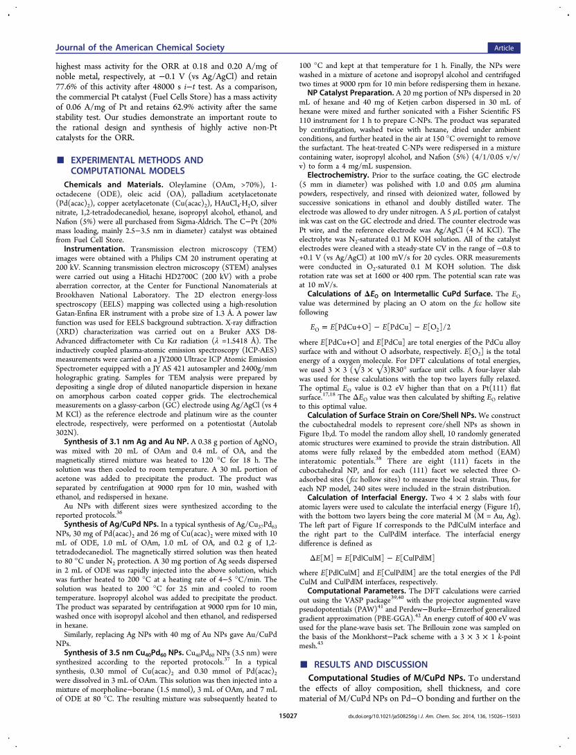
NPs was further compared with that of the commercial Ptcatalyst in the O2-saturated 0.1 M KOH solution (Figure 5a).Both Au/Cu40Pd60 and Ag/Cu37Pd63 NPs have half-wavepotentials more positive than that of the commercial Ptcatalyst. In order to give quantitative information on the ORRactivity of different catalysts, the corresponding Tafel plots(Figure 5b) and ORR mass activities at −0.1 V (normalizedagainst all noble metals present in the catalyst) were
Figure 5. (a−c) ORR polarization curves (a), Tafel plots (b), and ORR mass activity summaries (c) at −0.1 V of Ag/Cu37Pd63, Au/Cu40Pd60, andcommercial Pt in O2-saturated 0.1 M KOH solution at 293 K. Scan rate: 10 mV/s. Rotation rate: 400 rpm. (d) Chronoamperometric responses forthe ORR on Ag/Cu37Pd63 NPs and commercial Pt at −0.3 V. Rotation rate: 200 rpm.
Journal of the American Chemical Society Article
dx.doi.org/10.1021/ja508256g | J. Am. Chem. Soc. 2014, 136, 15026−1503315031
summarized (Figure 5c). Figure 5b gives a general informationon how high a current density we can obtain at differentpotentials, while Figure 5c shows that the mass activities of theAg/Cu37Pd63 (0.18 A/mg of Pd) and Au/Cu40Pd60 (0.20 A/mgof Au+Pd) obtained at the rotation of 400 rpm are nearly thesame. As a comparison, the mass activity of the commercial Ptcatalyst is only 0.06 A/mg of Pt under the same detectionconditions (Figure 5c). The durability of the Ag/CuPd NPsand Pt was evaluated by using a chronoamperometric methodat −0.30 V, a potential located at the mixed kinetic region(Figure 5d). The Ag/CuPd catalyst retains the higher currentvalues (77.6% retention) than the Pt catalyst (62.9% retention)after a 48000 s i−t test, demonstrating the longer-term stabilityof Au/CuPd over Pt. To the best of our knowledge, these Ag/Cu37Pd63 and Au/Cu40Pd60 catalysts are the best non-Ptcatalysts developed for catalyzing the ORR in alkaline solution.
■ CONCLUSIONS
To summarize, our DFT calculations predict that M/CuPd (M= Ag, Au) NPs with 0.8 and 1.2 nm CuPd2 shells have theoptimal surface strain and composition to catalyze ORR. Weprepared monodisperse M/CuPd NPs experimentally bycoreduction of Pd(acac)2 and Cu(acac)2 in the presence of3.1 nm Ag or Au seeds with shell thicknesses controlled at 0.4,0.75, and 1.1 nm and compositions at Cu20Pd80, Cu37Pd63, andCu55Pd45. These controls allow us to tune both shell electronicstructure and surface strain to maximize ORR performance. In0.1 M KOH solution, the Au/Cu40Pd60 and Ag/Cu37Pd63catalysts with 0.75 and 1.1 nm shell coatings are more efficientfor ORR than any other M/CuPd catalysts with different Cu/Pd compositions, CuPd NPs, and Ag studied in this paper.They have a mass activity of about 0.20 A/mg of noble metalthat is over 3 times higher than that from the commercial Pt(0.06 A/mg of Pt). They also exhibit higher durability than thePt catalyst, retaining 77.6% of their activity after 48000 s i−ttest (62.9% for the Pt catalyst). Our study highlights theimportant aspect of tuning surface strain and composition inthe core/shell structure to maximize its ORR performance andto develop more advanced NP catalysts with ORR catalysissuperior to that of Pt. The strategy demonstrated here can beextended to other core/shell systems, making it possible todesign and tune NP catalysis for other important chemicalreactions.
■ ASSOCIATED CONTENT
*S Supporting InformationFigure S1−S9, giving additional structures, TEM images, andplots. This material is available free of charge via the Internet athttp://pubs.acs.org.
Present Address∥Physical Chemistry and Applied Spectroscopy, Los AlamosNational Laboratory, Los Alamos, NM 87545, USA.
NotesThe authors declare no competing financial interest.
■ ACKNOWLEDGMENTS
This work was supported by the U.S. Army ResearchLaboratory and the U.S. Army Research Office under theMulti University Research Initiative (MURI, grant numberW911NF-11-1-0353) on “Stress-Controlled Catalysis viaEngineered Nanostructures”. Electron microscopy work carriedout at the Center for Functional Nanomaterials, BrookhavenNational Laboratory, was supported by the U.S. Department ofEnergy, Office of Basic Energy Sciences, under Contract No.DE-AC02-98CH10886.
■ REFERENCES(1) Voiry, D.; Yamaguchi, H.; Li, J.; Silva, R.; Alves, D. C. B.; Fujita,T.; Chen, M.; Asefa, T.; Shenoy, V. B.; Eda, G.; Chhowalla, M. Nat.Mater. 2013, 12, 850−855.(2) Liu, M.; Zhang, R.; Chen, W. Chem. Rev. 2014, 114, 5117−5160.(3) Ji, X.; Lee, K. T.; Holden, R.; Zhang, L.; Zhang, J.; Botton, G. A.;Couillard, M.; Nazar, L. F. Nat. Chem. 2010, 2, 286−293.(4) Liang, Y.; Li, Y.; Wang, H.; Zhou, J.; Wang, J.; Regier, T.; Dai, H.Nat. Mater. 2011, 10, 780−786.(5) Bing, Y.; Liu, H.; Zhang, L.; Ghosh, D.; Zhang, J. Chem. Soc. Rev.2010, 39, 2184−2202.(6) Chen, J.; Lim, B.; Lee, E. P.; Xia, Y. Nano Today 2009, 4, 81−95.(7) Zhang, H.; Jin, M.; Xia, Y. Chem. Soc. Rev. 2012, 41, 8035−8049.(8) Guo, S.; Zhang, S.; Sun, S. Angew. Chem., Int. Ed. 2013, 52, 8526.(9) Stamenkovic, V. R.; Mun, B. S.; Arenz, M.; Mayrhofer, K. J. J.;Lucas, C. A.; Wang, G.; Ross, P. N.; Markovic, N. M. Nat. Mater. 2007,6, 241−247.(10) Stamenkovic, V. R.; Fowler, B.; Mun, B. S.; Wang, G.; Ross, P.N.; Lucas, C. A.; Markovic, N. M. Science 2007, 315, 493−497.(11) Norskov, J. K.; Bligaard, T.; Rossmeisl, J.; Christensen, C. H.Nat. Chem. 2009, 1, 37−46.(12) Greeley, J.; Norskov, J. K.; Mavrikakis, M. Rev. Phys. Chem.2002, 53, 319−348.(13) Zhang, L.; Iyyamperumal, R.; Yancey, D. F.; Crooks, R. M.;Henkelman, G. ACS Nano 2013, 7, 9168−9172.(14) Zhang, S.; Zhang, X.; Jiang, G.; Zhu, H.; Guo, S.; Su, D.; Lu, G.;Sun, S. J. Am. Chem. Soc. 2014, 136, 7734−7739.(15) Strasser, P.; Koh, S.; Anniyev, T.; Greeley, J.; More, K.; Yu, C.;Liu, Z.; Kaya, S.; Nordlund, D.; Ogasawara, H.; Toney, M. F.; Nilsson,A. Nat. Chem. 2010, 2, 454−460.(16) Mavrikakis, M.; Hammer, M. B.; Nørskov, J. K. Phys. Rev. Lett.1999, 81, 2819.(17) Norskov, J. K.; Rossmeisl, J.; Logadottir, A.; Lindqvist, L. J. Phys.Chem. B 2004, 108, 17886−17892.(18) Stamenkovic, V.; Mun, B. S.; Mayrhofer, K. J. J.; Ross, P. N.;Markovic, N. M.; Rossmeisl, J.; Greeley, J.; Nørskov, J. K. Angew.Chem., Int. Ed. 2006, 45, 2897−2901.(19) Lim, B.; Jiang, M.; Camargo, P. H. C.; Cho, E. C.; Tao, J.; Lu,X.; Zhu, Y.; Xia, Y. Science 2009, 324, 1302−1305.(20) van der Vliet, D. F.; Wang, C.; Tripkovic, D.; Strmcnik, D.;Zhang, X. F.; Debe, M. K.; Atanasoski, R. T.; Markovic, N. M.;Stamenkovic, V. R. Nat. Mater. 2012, 11, 1051−1058.(21) Cui, C.; Gan, L.; Heggen, M.; Rudi, S.; Strasser, P. Nat. Mater.2013, 12, 765−771.(22) Wang, C.; Chi, M.; Li, D.; Strmcnik, D.; van der Vliet, D.; Wang,G.; Komanicky, V.; Chang, K.-C.; Paulikas, A. P.; Tripkovic, D.;Pearson, J.; More, K. L.; Markovic, N. M.; Stamenkovic, V. R. J. Am.Chem. Soc. 2011, 133, 14396−14403.(23) Kim, J.; Lee, Y.; Sun, S. J. Am. Chem. Soc. 2010, 132, 4996−4997.(24) Wang, D.; Xin, H. L.; Hovden, R.; Wang, H.; Yu, Y.; Muller, D.A.; DiSalvo, F. J.; Abruna, H. D. Nat. Mater. 2013, 12, 81−87.(25) Choi, S.-I.; Xie, S.; Shao, M.; Odell, J. H.; Lu, N.; Peng, H.-C.;Protsailo, L.; Guerrero, S.; Park, J.; Xia, X.; Wang, J.; Kim, M. J.; Xia, Y.Nano Lett. 2013, 13, 3420−3425.
Journal of the American Chemical Society Article
dx.doi.org/10.1021/ja508256g | J. Am. Chem. Soc. 2014, 136, 15026−1503315032