NANOMATERIALS Tunable porous nanoallotropes prepared by post-assembly etching of binary nanoparticle superlattices Thumu Udayabhaskararao, 1 Thomas Altantzis, 2 Lothar Houben, 3,4 Marc Coronado-Puchau, 5 Judith Langer, 5,6 Ronit Popovitz-Biro, 3 Luis M. Liz-Marzán, 5,6,7 Lela Vuković, 8 Petr Král, 9,10,11 Sara Bals, 2 Rafal Klajn 1 * Self-assembly of inorganic nanoparticles has been used to prepare hundreds of different colloidal crystals, but almost invariably with the restriction that the particles must be densely packed. Here, we show that non–close-packed nanoparticle arrays can be fabricated through the selective removal of one of two components comprising binary nanoparticle superlattices. First, a variety of binary nanoparticle superlattices were prepared at the liquid-air interface, including several arrangements that were previously unknown. Molecular dynamics simulations revealed the particular role of the liquid in templating the formation of superlattices not achievable through self-assembly in bulk solution. Second, upon stabilization, all of these binary superlattices could be transformed into distinct “nanoallotropes”—nanoporous materials having the same chemical composition but differing in their nanoscale architectures. S elf-assembly has emerged as the strategy of choice toward generating ordered arrays of nanosized particles. The resulting materials — in particular, those assembled from inorganic nanoparticles (NPs) (1–7)—often exhibit un- anticipated optical (8), thermoelectric (9), mag- netic (10), catalytic (11), and other (12) properties. The diversity of structures and presumably the properties of these materials could be greatly enhanced via postsynthetic modifications, which could be used to generate assemblies in which the constituent NPs are ordered yet separated by relatively large distances—that is, non–close- packed (NCP) NP arrays. Although several ex- amples of related materials have been reported, they are limited to highly specific systems, such as those involving highly directional interac- tions (13, 14) or a fine balance between attractive and repulsive forces during self-assembly (15). Thus, a general route to NCP NP arrays has been lacking. One strategy to tackle this limitation could be based on the selective removal (by means of chemical etching) of one type of NPs from binary NP superlattices (BNSLs) (1). Depending on the stoichiometry and structure of the initial BNSLs, this method could lead to “nanoallotropes”— materials that have the same chemical com- position but differ in their nanoscale architec- ture. Unfortunately, within BNSLs the two types of nanoscopic components mutually support each other, and removal of one would inevitably lead to the disruption of the other. Here, we hy- pothesized that this undesired behavior could be overcome by stabilizing the BNSL through controlled removal of the surfactants from the NP surfaces (16–18). If successful, this proce- dure would serve three purposes: (i) attaching the NPs to the underlying surface, (ii) control- ling the coalescence of the NPs, and (iii) ac- tivating the sacrificial component of the BNSL toward etching. We worked with monodisperse batches of Au and Fe 3 O 4 NPs (figs. S1 and S2) (19), which we assembled at the diethylene glycol (DEG)–air interface (Fig. 1A, step 1), as previously reported (20). After transfer onto a carbon-coated trans- mission electron microscopy (TEM) copper grid (Fig. 1A, step 2) and a controlled, thermally in- duced desorption of ligands from the NPs (Fig. 1A, step 3) ( 17), the samples were exposed to an etchant reacting with only one of the two materials (Fig. 1A, step 4). As a proof of concept, we co-assembled a ~1:1 mixture of 5.2 (±0.4) nm dodecanethiol- protected Au NPs and 10.6 (±0.6) nm oleate- protected Fe 3 O 4 NPs into the previously reported (20) AB-type binary NP monolayer (Fig. 1B and figs. S3 to S6) (19). After immobilization onto carbon-coated TEM grids, Fe 3 O 4 NPs could be etched out by immersing the substrate into an aqueous solution of HCl, without affecting the order of the gold NPs (Fig. 1C). For example, shown in Fig. 1E is an ensemble of 250 gold NPs, the positions of which all remained unaffected af- ter HCl etching (figs. S7 and S8) (19). We will refer to the resulting NCP array of Au NPs as vac 1 Au 1 , where vac denotes “vacancy.” Alternatively, a square array of self-supporting Fe 3 O 4 NPs could be obtained by treating the BNSLs with a cyanide solution, which can selectively dissolve Au NPs (Fig. 1D). The underlying substrate had a profound effect on the successful fixation of the NPs. The NPs could be readily immobilized on commer- cial carbon-coated Formvar films as well as on homemade carbon-coated nitrocellulose sub- strates. However, we found no attachment onto silicon wafers or nitrocellulose that lacked a layer of amorphous carbon (fig. S9) (19). From these results, we conclude that amorphous carbon fa- cilitated the desorption of organic ligands from the NP surfaces and the formation of a carbo- naceous film (21), which can serve as an adhesive for the NPs. The carbonaceous films can be di- rectly visualized with TEM (fig. S10) (19). Overall, the above procedure allowed for the fabrication of NCP NP superlattices on thin, flexible sub- strates (Fig. 1C, inset), which could subsequently be transferred onto surfaces of choice. Self-assembly from a ~5:1 mixture of Au and Fe 3 O 4 NPs resulted in a different type of BNSL, as shown in Fig. 2A (fig. S11) (19). This array, featuring alternating clusters of Au NPs and in- dividual Fe 3 O 4 NPs, is akin to the previously re- ported Fe 4 C-type BNSL (22). However, selective removal of the Fe 3 O 4 counterpart allowed us to observe quintets—rather than quartets—of Au NPs arranged in a tetrahedral geometry (Fig. 2B and fig. S12) (19). To decipher the structure of this and other more complex assemblies, we conducted electron tomography studies ( 23, 24) by acquiring series of two-dimensional (2D) projections of the etched arrays over a wide range of tilt angles using high-angle annular dark-field scanning transmis- sion electron microscopy (HAADF-STEM). These studies confirmed that each cluster was com- posed of five Au NPs (giving rise to stoichiometry vac 1 Au 5 ) (figs. S13 to S15) (19), and they helped elucidate the mutual packing of the resulting tetrahedra (Fig. 2, C and D, and database S1, tomography data) (19). The high stability of these tetrahedra could be attributed to partial coales- cence of Au NPs, which occurred as a result of ligand desorption (16–18). As shown in the struc- tural model in fig. S16, the vac 1 Au 5 array is derived from an incomplete (deficient in Au) AB 6 -type BNSL (19). Our method allowed us to control the degree of coalescence by adjusting the time of thermal treatment; extending the heating time from 30 min to 6 hours allowed us to convert an en- semble of tetrahedra into a well-defined array of pseudospherical ~9-nm gold NPs (figs. S17 to S19) (19). An unexpected effect of heating was that Au NP quintets that lack a strong attach- ment to the underlying substrate could migrate and be transformed into well-defined sinuous nanowires (fig. S20) (19). Increasing the Au:Fe 3 O 4 NP ratio to ~10 led to another type of BNSL, which, after the removal RESEARCH Udayabhaskararao et al., Science 358, 514–518 (2017) 27 October 2017 1 of 5 1 Department of Organic Chemistry, Weizmann Institute of Science, Rehovot 76100, Israel. 2 EMAT, University of Antwerp, Groenenborgerlaan 171, B-2020 Antwerp, Belgium. 3 Department of Chemical Research Support, Weizmann Institute of Science, Rehovot 76100, Israel. 4 Ernst Ruska- Centre for Microscopy and Spectroscopy with Electrons, 52425 Jülich, Germany. 5 CIC BiomaGUNE, Paseo de Miramón 182, 20014 Donostia-San Sebastián, Spain. 6 Biomedical Research Networking Center in Bioengineering, Biomaterials, and Nanomedicine (CIBER-BBN), 20014 Donostia-San Sebastián, Spain. 7 Ikerbasque, Basque Foundation for Science, 48013 Bilbao, Spain. 8 Department of Chemistry, University of Texas at El Paso, El Paso, TX 79968, USA. 9 Department of Chemistry, University of Illinois at Chicago, Chicago, IL 60607, USA. 10 Department of Physics, University of Illinois at Chicago, Chicago, IL 60607, USA. 11 Department of Biopharmaceutical Sciences, University of Illinois at Chicago, Chicago, IL 60607, USA. *Corresponding author. Email: [email protected]on October 26, 2017 http://science.sciencemag.org/ Downloaded from
Transcript
NANOMATERIALS
Tunable porous nanoallotropesprepared by post-assembly etching ofbinary nanoparticle superlatticesThumu Udayabhaskararao,1 Thomas Altantzis,2 Lothar Houben,3,4
Marc Coronado-Puchau,5 Judith Langer,5,6 Ronit Popovitz-Biro,3
Luis M. Liz-Marzán,5,6,7 Lela Vuković,8 Petr Král,9,10,11 Sara Bals,2 Rafal Klajn1*
Self-assembly of inorganic nanoparticles has been used to prepare hundreds of differentcolloidal crystals, but almost invariably with the restriction that the particles must bedensely packed. Here,we show that non–close-packed nanoparticle arrays can be fabricatedthrough the selective removal of one of two components comprising binary nanoparticlesuperlattices. First, a variety of binary nanoparticle superlattices were prepared at theliquid-air interface, including several arrangements that were previously unknown.Moleculardynamics simulations revealed the particular role of the liquid in templating the formationof superlattices not achievable through self-assembly in bulk solution. Second, uponstabilization, all of these binary superlattices could be transformed into distinct“nanoallotropes”—nanoporous materials having the same chemical composition butdiffering in their nanoscale architectures.
Self-assembly has emerged as the strategy ofchoice toward generating ordered arrays ofnanosized particles. The resultingmaterials—in particular, those assembled from inorganicnanoparticles (NPs) (1–7)—often exhibit un-
anticipated optical (8), thermoelectric (9), mag-netic (10), catalytic (11), and other (12) properties.The diversity of structures and presumably theproperties of these materials could be greatlyenhanced via postsynthetic modifications, whichcould be used to generate assemblies in whichthe constituent NPs are ordered yet separated byrelatively large distances—that is, non–close-packed (NCP) NP arrays. Although several ex-amples of related materials have been reported,they are limited to highly specific systems, suchas those involving highly directional interac-tions (13, 14) or a fine balance between attractiveand repulsive forces during self-assembly (15).Thus, a general route to NCP NP arrays has beenlacking.One strategy to tackle this limitation could
be based on the selective removal (by means of
chemical etching) of one type of NPs from binaryNP superlattices (BNSLs) (1). Depending on thestoichiometry and structure of the initial BNSLs,this method could lead to “nanoallotropes”—materials that have the same chemical com-position but differ in their nanoscale architec-ture. Unfortunately, within BNSLs the two typesof nanoscopic components mutually supporteach other, and removal of one would inevitablylead to the disruption of the other. Here, we hy-pothesized that this undesired behavior couldbe overcome by stabilizing the BNSL throughcontrolled removal of the surfactants from theNP surfaces (16–18). If successful, this proce-dure would serve three purposes: (i) attachingthe NPs to the underlying surface, (ii) control-ling the coalescence of the NPs, and (iii) ac-tivating the sacrificial component of the BNSLtoward etching.We worked with monodisperse batches of Au
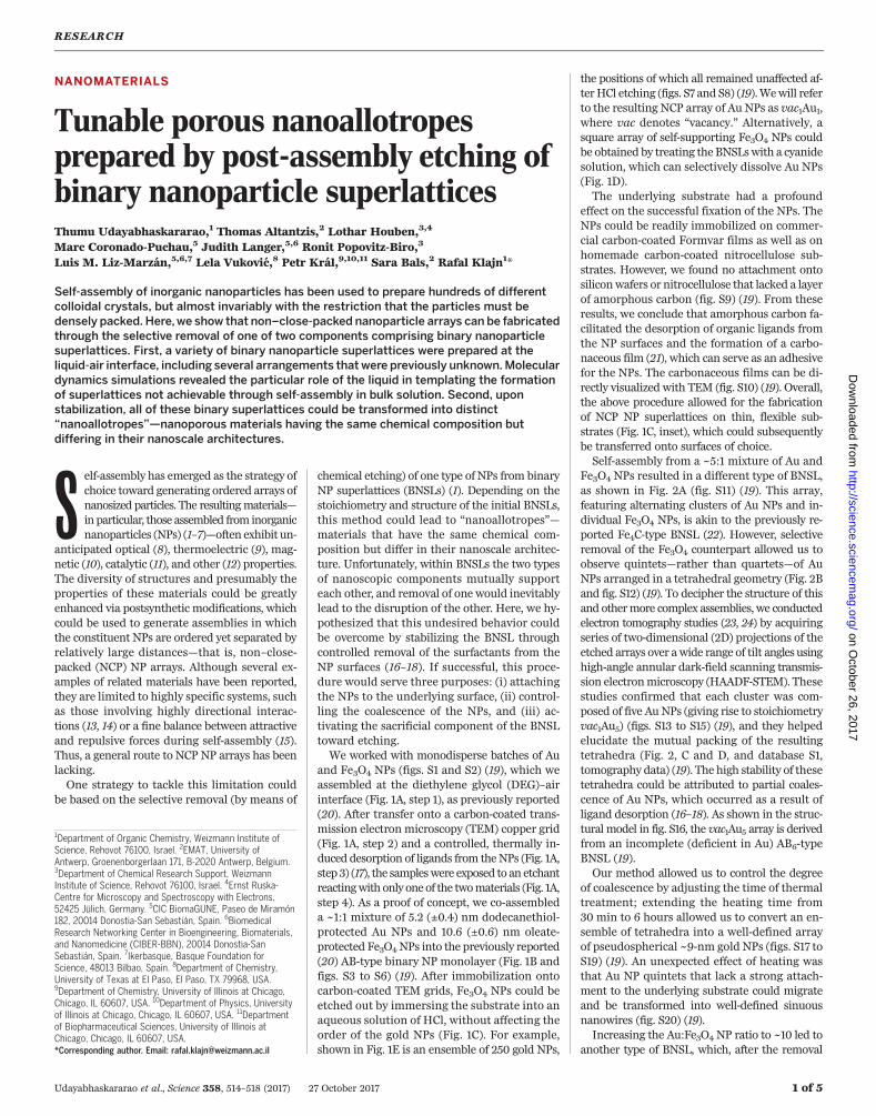
and Fe3O4 NPs (figs. S1 and S2) (19), which weassembled at the diethylene glycol (DEG)–airinterface (Fig. 1A, step 1), as previously reported(20). After transfer onto a carbon-coated trans-mission electron microscopy (TEM) copper grid(Fig. 1A, step 2) and a controlled, thermally in-duced desorption of ligands from theNPs (Fig. 1A,step 3) (17), the sampleswere exposed to an etchantreactingwith only oneof the twomaterials (Fig. 1A,step 4). As a proof of concept, we co-assembleda ~1:1 mixture of 5.2 (±0.4) nm dodecanethiol-protected Au NPs and 10.6 (±0.6) nm oleate-protected Fe3O4NPs into the previously reported(20) AB-type binary NP monolayer (Fig. 1B andfigs. S3 to S6) (19). After immobilization ontocarbon-coated TEM grids, Fe3O4 NPs could beetched out by immersing the substrate into anaqueous solution of HCl, without affecting theorder of the gold NPs (Fig. 1C). For example,shown in Fig. 1E is an ensemble of 250 gold NPs,
the positions of which all remained unaffected af-terHCl etching (figs. S7 and S8) (19).Wewill referto the resulting NCP array of Au NPs as vac1Au1,where vac denotes “vacancy.” Alternatively, asquare array of self-supporting Fe3O4 NPs couldbe obtained by treating the BNSLswith a cyanidesolution, which can selectively dissolve Au NPs(Fig. 1D).The underlying substrate had a profound
effect on the successful fixation of the NPs. TheNPs could be readily immobilized on commer-cial carbon-coated Formvar films as well as onhomemade carbon-coated nitrocellulose sub-strates. However, we found no attachment ontosiliconwafers or nitrocellulose that lacked a layerof amorphous carbon (fig. S9) (19). From theseresults, we conclude that amorphous carbon fa-cilitated the desorption of organic ligands fromthe NP surfaces and the formation of a carbo-naceous film (21), which can serve as an adhesivefor the NPs. The carbonaceous films can be di-rectly visualized with TEM (fig. S10) (19). Overall,the above procedure allowed for the fabricationof NCP NP superlattices on thin, flexible sub-strates (Fig. 1C, inset), which could subsequentlybe transferred onto surfaces of choice.Self-assembly from a ~5:1 mixture of Au and
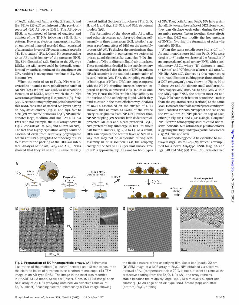
Fe3O4 NPs resulted in a different type of BNSL,as shown in Fig. 2A (fig. S11) (19). This array,featuring alternating clusters of Au NPs and in-dividual Fe3O4 NPs, is akin to the previously re-ported Fe4C-type BNSL (22). However, selectiveremoval of the Fe3O4 counterpart allowed us toobserve quintets—rather than quartets—of AuNPs arranged in a tetrahedral geometry (Fig. 2Band fig. S12) (19). To decipher the structure of thisand othermore complex assemblies, we conductedelectron tomography studies (23, 24) by acquiringseries of two-dimensional (2D) projections of theetched arrays over awide range of tilt angles usinghigh-angle annular dark-field scanning transmis-sion electronmicroscopy (HAADF-STEM). Thesestudies confirmed that each cluster was com-posed of five AuNPs (giving rise to stoichiometryvac1Au5) (figs. S13 to S15) (19), and they helpedelucidate the mutual packing of the resultingtetrahedra (Fig. 2, C and D, and database S1,tomography data) (19). The high stability of thesetetrahedra could be attributed to partial coales-cence of Au NPs, which occurred as a result ofligand desorption (16–18). As shown in the struc-tural model in fig. S16, the vac1Au5 array is derivedfrom an incomplete (deficient in Au) AB6-typeBNSL (19).Our method allowed us to control the degree
of coalescence by adjusting the time of thermaltreatment; extending the heating time from30 min to 6 hours allowed us to convert an en-semble of tetrahedra into a well-defined arrayof pseudospherical ~9-nm gold NPs (figs. S17 toS19) (19). An unexpected effect of heating wasthat Au NP quintets that lack a strong attach-ment to the underlying substrate could migrateand be transformed into well-defined sinuousnanowires (fig. S20) (19).Increasing the Au:Fe3O4 NP ratio to ~10 led to
another type of BNSL, which, after the removal
RESEARCH
Udayabhaskararao et al., Science 358, 514–518 (2017) 27 October 2017 1 of 5
1Department of Organic Chemistry, Weizmann Institute ofScience, Rehovot 76100, Israel. 2EMAT, University ofAntwerp, Groenenborgerlaan 171, B-2020 Antwerp, Belgium.3Department of Chemical Research Support, WeizmannInstitute of Science, Rehovot 76100, Israel. 4Ernst Ruska-Centre for Microscopy and Spectroscopy with Electrons,52425 Jülich, Germany. 5CIC BiomaGUNE, Paseo de Miramón182, 20014 Donostia-San Sebastián, Spain. 6BiomedicalResearch Networking Center in Bioengineering, Biomaterials,and Nanomedicine (CIBER-BBN), 20014 Donostia-SanSebastián, Spain. 7Ikerbasque, Basque Foundation forScience, 48013 Bilbao, Spain. 8Department of Chemistry,University of Texas at El Paso, El Paso, TX 79968, USA.9Department of Chemistry, University of Illinois at Chicago,Chicago, IL 60607, USA. 10Department of Physics, Universityof Illinois at Chicago, Chicago, IL 60607, USA. 11Departmentof Biopharmaceutical Sciences, University of Illinois atChicago, Chicago, IL 60607, USA.*Corresponding author. Email: [email protected]
of Fe3O4, exhibited features (Fig. 2, E and F, andfigs. S21 to S23) (19) reminiscent of the previouslyreported (25) AB13-type BNSL. The AB13-typeBNSL is composed of layers of quartets andquintets of the “B” NPs, following a (-B4-B5-B4-)npattern. However, electron tomography studieson our etched material revealed that it consistedof alternating layers of NP quartets and septets [a(-B4-B7-)n pattern] (Fig. 2, G andH), correspondingto an AB11 stoichiometry of the precursor BNSL(fig. S24, discussion) (19). Similar to the AB6-typeBNSLs, the AB11 arrays could be thermally trans-formed by partial sintering of the constituent AuNPs, resulting in nanoporousmembranes (fig. S25,bottom) (19).When the ratio of Au to Fe3O4 NPs was de-
creased to ~4 and a more polydisperse batch ofAuNPs (4.9 ± 0.7 nm) was used, we observed theformation of BNSLs, within which the Au NPswere arranged into zigzag-like patterns (fig. S26)(19). Electron tomography analysis showed thatthis BNSL consisted of stacked NP layers havingan AB4 stoichiometry (Fig. 2I and figs. S27 toS29) (19), where “A” denotes a Fe3O4 NP and “B”denotes large, medium, and small Au NPs in a1:2:1 ratio (for example, the NCP array shown inFig. 2I consists of 6.2-, 5.3-, and 4.1-nm Au NPs).The fact that highly crystalline arrays could beassembled even from relatively polydispersebatches of NPs highlights the tendency of NPsto maximize the packing at the DEG-air inter-face. Analysis of the AB4, AB6, and AB11 BNSLsshowed that they all share the same densely
packed initial (bottom) monolayer [Fig. 2, D,H, and I, and figs. S16, S25, and S29, structuralmodels (19)].The formation of the above AB4, AB6, AB11,
and other structures not observed during self-assembly in three dimensions (bulk solution) sug-gests a profound effect of DEG on the assemblyprocess (26, 27). To disclose the mechanisms thatgovern self-assembly in our system, we performedprecise atomistic molecular dynamics (MD) sim-ulations of NPs at different liquid-air interfaces.These simulations, detailed in the supplementarymaterials, revealed that the role of DEG in guidingNP self-assembly is the result of a combination ofseveral effects (19). First, the coupling energiesof both types of NPs to DEG are large comparedwith the NP-NP coupling energies between ex-posed or partly submerged NPs (tables S1 andS2) (19). Hence, the NPs exhibit a high affinity tothe surface of the underlying liquid, which theytend to cover in the most efficient way. Analysisof BNSLs assembled on the surface of DEGshowed that as much as >50% of the latticeenergies originates from NP-DEG, rather thanNP-NP coupling (19). Second, both dodecanethiol-protected Au NPs and oleate-protected Fe3O4
NPs preferentially submerge in DEG to abouthalf their diameter (Fig. 2, J to L). As a result,DEG can organize the bottom layer of NPs in away that may not be achievable during self-assembly in bulk solution. Last, the couplingenergy of the NPs to DEG per unit surface areaof NP is approximately the same for both types
of NPs. Thus, both Au and Fe3O4 NPs have a sim-ilar affinity toward the surface of DEG, fromwhichthey can displace each other during the self-assembly process. Taken together, these effectsshow that DEG can modify the free energiesof BNSLs, favoring the formation of otherwiseunstable BNSLs.When the same polydisperse (4.9 ± 0.7 nm)
Au and monodisperse 10.6 nm Fe3O4 NPs wereused in a ~5:1 ratio, we observed the formation ofan unprecedented quasi-ternary BNSLwith a stoi-chiometry ABC4, where “B” denotes a small(~4.0 nm) and “C” denotes a large (~5.5 nm) AuNP (fig. S30) (19). Subjecting this superlatticeto our stabilization-etching procedure affordeda NCP vac1Au1Au′4 array shown in Fig. 2, M toP (here, Au and Au′ denote small and large AuNPs, respectively) (figs. S31 to S34) (19). Withinthe ABC4-type BNSL, the bottom-most Au andFe3O4 NPs have their bottom boundaries (ratherthan the equatorial cross sections) at the samelevel. However, the “half-submergence condition”is still satisfied for both NP types if one considersthe two 5.5-nm Au NPs placed on top of eachother (in Fig. 2P, C and C′) as a single, elongatedNP. Electron tomography studies could not re-solve individualNPswithin these putative dimers,suggesting that they undergo a partial coalescence(Fig. 2O, blue and red).Our methodology could be extended to mul-
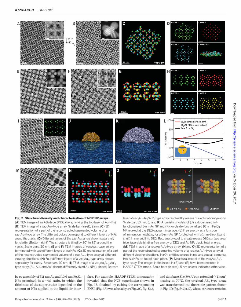
tilayers (figs. S35 to S43) (19), which is exempli-fied for a novel AB4-type BNSL (Fig. 3A andfigs. S40 and S44) (19). This BNSL was obtained
Udayabhaskararao et al., Science 358, 514–518 (2017) 27 October 2017 2 of 5
Fig. 1. Preparation of NCP nanoparticle arrays. (A) Schematicillustration of the method (“e– beam” denotes an ~10 min exposure tothe electron beam of a transmission electron microscope. (B) TEMimage of an AB-type BNSL. The image in the inset was recordedin HAADF-STEM mode. Scale bar (inset), 5 nm. (C) TEM image of anNCP array of Au NPs (vac1Au1) obtained via selective removal ofFe3O4. (Inset) Scanning electron microscopy (SEM) image showing
the flexible nature of the underlying film. Scale bar (inset), 20 nm.(D) SEM image of a NCP array of Fe3O4 NPs obtained via selectiveremoval of Au [temperature below 70°C is not sufficient to remove theprotective coating from the Fe3O4 NPs (21); the array remainsstable because the relatively large Fe3O4 NPs mutually support oneanother]. (E) An edge of an AB-type BNSL before (top) and after(bottom) Fe3O4 etching.
NPs premixed in a ~4:1 ratio, in which thethickness of the superlattice depended on theamount of NPs applied at the liquid-air inter-
face. For example, HAADF-STEM tomographyrevealed that the NCP superlattice shown inFig. 3B obtained by etching the correspondingBNSL (Fig. 3A) was a hexalayer (Fig. 3C, fig. S43,
and database S1) (19). Upon extended (>1 hour)heating at 70°C, the original AB4-type arraywas transformed into the exotic pattern shownin Fig. 3D (fig. S42) (19), whose structure remains
Udayabhaskararao et al., Science 358, 514–518 (2017) 27 October 2017 3 of 5
Fig. 2. Structural diversity and characterization of NCP NP arrays.(A) TEM image of an AB6-type BNSL (here, lacking the top layer of Au NPs).(B) TEM image of a vac1Au5-type array. Scale bar (inset), 2 nm. (C) 3Drepresentation of a part of the reconstructed segmented volume of avac1Au5-type array.The different colors correspond to different layers of NPsalong the z axis. (D) Different layers of the vac1Au5 array shown separatelyfor clarity. (Bottom right) The structure is tilted by 80° to 85° around thex axis. Scale bars, 20 nm. (E and F) TEM images of vac1Au11-type arraysterminated with two different layers of Au NPs. (G) 3D representation of a partof the reconstructed segmented volume of a vac1Au11-type array at differentviewing directions. (H) Four different layers of a vac1Au11-type array shownseparately for clarity. Scale bars, 10 nm. (I) TEM image of a vac1Au1Au2′Au′′1-type array (Au, Au′, and Au′′ denote differently sized AuNPs). (Inset) Bottom
layer of vac1Au1Au2′Au′′1-type array resolved bymeans of electron tomography.Scale bar, 10 nm. (J and K) Atomistic models of (J) a dodecanethiol-functionalized 5-nm Au NP and (K) an oleate-functionalized 10 nm Fe3O4
NP relaxed at the DEG-vacuum interface. (L) Free energy as a functionof immersion height, h, for a 5-nm Au NP (protected with a 1-nm-thick ligandshell) immersed into DEG. Red, energy cost to create excess DEG surface area;blue, favorable binding free energy of DEG and Au NP; black, total energy.(M) TEM image of a vac1Au1Au′4-type array. (N and O) 3D representation of apart of the reconstructed segmented volume of a vac1Au1Au′4-type array atdifferent viewing directions. In (O), entities colored in red and blue all comprisetwo Au NPs on top of each other. (P) Structural model of the vac1Au1Au′4-type array.The images in the insets in (B) and (E) have been recorded inHAADF-STEM mode. Scale bars (insets), 5 nm unless indicated otherwise.
to be identified. Detailed theoretical analysis inthe supplementary materials confirms that ourtechnique can in principle be extended to NCParrays having thicknesses approaching macro-scopic dimensions (19).Our methodology can also be applied to NP
building blocks of other sizes. For example, inFig. 3, F and G, we extended the average distancebetween 5.2-nm Au NPs within vac1Au1 arraysfrom 12.5 to 15.3 nmby simply increasing the sizeof the Fe3O4 NPs with which they were co-assembled from 10.6 to 13.0 nm. These resultsindicate the ability to pattern solid substrateswithnanoscopicAudomains, with subnanometerprecision.When the sizes of both Au (5.2 nm) andFe3O4 (10.6 nm) NPs were decreased (to 3.0 and8.4 nm, respectively), many of the BNSLs and theresulting NCP arrays could be recreated on asmaller scale (fig. S45) (19). Similarly, workingwith mixtures of 5.2-nm Au NPs and 8.4-nmFe3O4, we obtained AB-, AB4-, and ABC4-typeand other BNSLs described above (fig. S46) (19).In addition, the modified NP size ratio resultedin novel NP arrays, such as the vac1Au2-type andthe vac2Au1-type structures shown in Fig. 3, Hand I (fig. S47) (19). The main drawbacks of ourmethod lie in the inherent difficulties in pre-paring defect-free BNSLs, which limited thesize of single-crystalline domains of BNSLs, andhence of NCP arrays, up to several micrometers.In addition, it has proven challenging to controlthe film thickness throughout the entire area ofthe sample—for example, a 1:1 mixture of Auand Fe3O4 NPs predicted to give rise to a mono-layer of the AB-type BNSL afforded a ~20:1:1mixture of monolayer, bilayer, and noncoatedsubstrate.
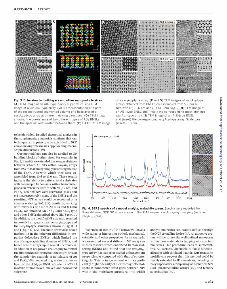
We envision that NCP NP arrays will have awide range of interesting optical, mechanical,catalytic, and other properties. As an example,we examined several different NP arrays assubstrates for surface-enhanced Raman scat-tering (SERS) and found that the vac1Au11-type array has superior signal enhancementproperties, as compared with that of vac1Au5(Fig. 4). This is in agreement with a signifi-cantly higher density of electromagnetic hot-spots at nanometer-sized gaps between NPswithin the multilayer structure, into which
analyte molecules can readily diffuse throughthe NCP crystalline lattice (19). An attractive ave-nue will be to use the well-defined nanoporeswithin thesematerials for trapping active proteinmolecules. Our procedure leads to surfactant-free Au surfaces, amenable to facile function-alization with thiolated ligands. Our results onmultilayers suggest that this method could bereadily extended to 3D assemblies, including bi-nary superlattices comprising nonspherical NPs(28), quasicrystalline arrays (29), and ternarysuperlattices (30).
Udayabhaskararao et al., Science 358, 514–518 (2017) 27 October 2017 4 of 5
Fig. 3. Extension to multilayers and other nanoparticle sizes.(A) TEM image of an AB4-type binary superlattice. (B) TEMimage of a vac1Au4-type array. (C) 3D representation of a partof the reconstructed segmented volume of a hexalayer of avac1Au4-type array at different viewing directions. (D) TEM imageshowing the coexistence of two different types of AB4 BNSLsand the epitaxial relationship between them. (E) HAADF-STEM image
of a vac1Au4-type array. (F and G) TEM images of vac1Au1-typearrays obtained from BNSLs co-assembled from 5.2-nm AuNPs with (F) 10.6 nm and (G) 13.0 nm Fe3O4. (H) TEM image ofan AB2-type BNSL and (inset) the corresponding (post-etching)vac1Au2-type array. (I) TEM image of an A2B-type BNSLand (inset) the corresponding vac2Au1-type array. Scale bars(insets), 10 nm.
Fig. 4. SERS spectra of a model analyte, malachite green. Spectra were recorded fromthree different NCP NP arrays shown in the TEM images: vac1Au1 (gray), vac1Au5 (red), andvac1Au11 (blue).
1. E. V. Shevchenko, D. V. Talapin, N. A. Kotov, S. O’Brien,C. B. Murray, Nature 439, 55–59 (2006).
2. N. A. Kotov, F. C. Meldrum, C. Wu, J. H. Fendler, J. Phys. Chem.98, 2735–2738 (1994).
3. S. Y. Park et al., Nature 451, 553–556 (2008).4. Z. Tang, Z. Zhang, Y. Wang, S. C. Glotzer, N. A. Kotov, Science
314, 274–278 (2006).5. D. Nykypanchuk, M. M. Maye, D. van der Lelie, O. Gang, Nature
451, 549–552 (2008).6. G. Singh et al., Science 345, 1149–1153 (2014).7. T. Wang et al., Science 338, 358–363 (2012).8. E. V. Shevchenko et al., J. Am. Chem. Soc. 130, 3274–3275
(2008).9. M. Ibáñez et al., Nat. Commun. 7, 10766 (2016).10. A. Dong, J. Chen, X. Ye, J. M. Kikkawa, C. B. Murray,
J. Am. Chem. Soc. 133, 13296–13299 (2011).11. Y. Kang et al., J. Am. Chem. Soc. 135, 42–45 (2013).12. J. J. Urban, D. V. Talapin, E. V. Shevchenko, C. R. Kagan,
C. B. Murray, Nat. Mater. 6, 115–121 (2007).13. M. P. Boneschanscher et al., Science 344, 1377–1380
(2014).14. H. Lin et al., Science 355, 931–935 (2017).15. A. M. Kalsin et al., Science 312, 420–424 (2006).
16. C. J. Kiely, J. Fink, M. Brust, D. Bethell, D. J. Schiffrin, Nature396, 444–446 (1998).
17. Y. Yu, C. A. Bosoy, D. M. Smilgies, B. A. Korgel, J. Phys. Chem.Lett. 4, 3677–3682 (2013).
18. T. Altantzis, Z. J. Yang, S. Bals, G. Van Tendeloo, M. P. Pileni,Chem. Mater. 28, 716–719 (2016).
19. Materials and methods are available as supplementary materials.20. A. Dong, J. Chen, P. M. Vora, J. M. Kikkawa, C. B. Murray,
Nature 466, 474–477 (2010).21. Y. Jiao et al., Nat. Commun. 6, 6420 (2015).22. E. V. Shevchenko, D. V. Talapin, C. B. Murray, S. O’Brien, J. Am.
Chem. Soc. 128, 3620–3637 (2006).23. H. Friedrich et al., Nano Lett. 9, 2719–2724 (2009).24. M. P. Boneschanscher et al., Nano Lett. 13, 1312–1316 (2013).25. E. V. Shevchenko, D. V. Talapin, S. O’Brien, C. B. Murray, J. Am.
Chem. Soc. 127, 8741–8747 (2005).26. V. Aleksandrovic et al., ACS Nano 2, 1123–1130 (2008).27. A. Dong, X. Ye, J. Chen, C. B. Murray, Nano Lett. 11, 1804–1809
(2011).28. X. Ye et al., Nat. Chem. 5, 466–473 (2013).29. Z. Yang, J. Wei, P. Bonville, M. P. Pileni, J. Am. Chem. Soc. 137,
4487–4493 (2015).30. W. H. Evers, H. Friedrich, L. Filion, M. Dijkstra, D. Vanmaekelbergh,
Angew. Chem. Int. Ed. 48, 9655–9657 (2009).
ACKNOWLEDGMENTS
This work was supported by the European Research Council (grants336080 CONFINEDCHEM to R.K. and 335078 COLOURATOM to S.B.),the Rothschild Caesarea Foundation (R.K.), the NSF (Division of MaterialsResearch, grant 1506886) (P.K.), the European Commission (grantEUSMI 731019 to L.M.L.-M. and S.B.), and the startup funding from theUniversity of Texas at El Paso (L.V.). L.M.L.-M. acknowledges funding fromthe Spanish Ministerio de Economía y Competitividad (grant MAT2013-46101-R). T.A. acknowledges funding from the Research FoundationFlanders (FWO, Belgium) through a postdoctoral grant. The computersupport was provided by the Texas Advanced Computing Center. All dataare reported in the main text and supplementary materials.
SUPPLEMENTARY MATERIALS
www.sciencemag.org/content/358/6362/514/suppl/DC1Materials and MethodsSupplementary TextFigs. S1 to S52Tables S1 to S5Caption for Database S1References (31–52)
7 May 2017; accepted 21 September 201710.1126/science.aan6046
Udayabhaskararao et al., Science 358, 514–518 (2017) 27 October 2017 5 of 5
superlatticesTunable porous nanoallotropes prepared by post-assembly etching of binary nanoparticle
Luis M. Liz-Marzán, Lela Vukovic, Petr Král, Sara Bals and Rafal KlajnThumu Udayabhaskararao, Thomas Altantzis, Lothar Houben, Marc Coronado-Puchau, Judith Langer, Ronit Popovitz-Biro,
, this issue p. 514; see also p. 448Scienceclose-packed arrays with vacancies stabilized by the carbon surface.−nanoparticles created non
could then be transferred to carbon-coated surfaces (see the Perspective by Kotov). Selective etching of either of the formed binary superlattices of gold and magnetite nanoparticles at an air-liquid interface that et al.Udayabhaskararao
component removed, then a more open array could form, as long as the remaining nanoparticles could be stabilized. Films of colloidal nanoparticles usually form dense, close-packed lattices. If binary lattices could be made and one