60
NANOSPOT 300 MINI MOVING HEAD 30 W WITH IR REMOTE CLNS300 USER´S MANUAL BEDIENUNGSANLEITUNG MANUEL D`UTILISATION MANUAL DE USUARIO INSTRUKCJA OBSŁUGI MANUALE D‘ USO
NANOSPOT 300MINI MOVING HEAD 30 W WITH IR REMOTE CLNS300
USER´S MANUALBEDIENUNGSANLEITUNG MANUEL D`UTILISATIONMANUAL DE USUARIOINSTRUKCJA OBSŁUGIMANUALE D‘ USO
CONTENTS / INHALTSVERZEICHNIS / CONTENU / CONTENIDO / TREŚĆ / CONTENUTO
ENGLISHPREVENTIVE MEASURES 3-4INTRODUCTIONCONNECTIONS, CONTROLS AND INDICATORSOPERATIONIR REMOTE CONTROLSETTING UP AND MOUNTINGTECHNICAL SPECIFICATIONSMANUFACTURER’S DECLARATIONSDMX CONTROL
DEUTSCHSICHERHEITSHINWEISEEINFÜHRUNGANSCHLÜSSE, BEDIEN- UND ANZEIGEELEMENTEBEDIENUNGIR FERNBEDIENUNGAUFSTELLUNG UND MONTAGETECHNISCHE DATENHERSTELLERERKLÄRUNGENDMX STEUERUNG
FRANCAISMESURES PRÉVENTIVES 22-23INTRODUCTIONCONNECTEURS, CONTRÔLES ET INDICATEURSUTILISATIONTÉLÉCOMMANDE INFRAROUGEMISE EN PLACE ET MONTAGECARACTÉRISTIQUES TECHNIQUESPRÉCISIONS FABRICANTPILOTAGE DMX
ESPAÑOLMEDIDAS DE SEGURIDAD 31-32INTRODUCCIÓNCONEXIONES, CONTROLES E INDICADORESOPERACIÓNMANDO A DISTANCIA POR INFRARROJOSINSTALACIÓN Y MONTAJECARACTERÍSTICAS TÉCNICASDECLARACIÓN DEL FABRICANTECONTROL DMX
POLSKIŚRODKI OSTROŻNOŚCI 40-41WSTĘPZŁĄCZA, ELEMENTY OBSŁUGI I WSKAŹNIKIOBSŁUGAPILOT NA PODCZERWIEŃUSTAWIENIE I MONTAŻDANE TECHNICZNEDEKLARACJE PRODUCENTASTEROWANIE DMX
ITALIANOMISURE PRECAUZIONALI 50-51INDICAZIONI SULLA SICUREZZAINTRODUZIONECONNESSIONI, ELEMENTI DI COMANDO E VISUALIZZAZIONEUTILIZZOTELECOMANDO A INFRAROSSIINSTALLAZIONE E MONTAGGIODATI TECNICIDICHIARAZIONI DEL FABBRICANTECONTROLLO DMX

ITALIANOPOLSKI
ESPAÑOLFRANCAIS
DEUTSCHENGLISH
3
DMX
ENGLISH
YOU‘VE MADE THE RIGHT CHOICE!We have designed this product to operate reliably over many years. Please read this User‘s Manual carefully, so that you can begin making optimum use of your Cameo Light product quickly. Learn more about Cameo Light on our website WWW.CAMEOLIGHT.COM.
PREVENTIVE MEASURES1. Please read these instructions carefully. 2. Keep all information and instructions in a safe place. 3. Follow the instructions. 4. Observe all safety warnings. Never remove safety warnings or other information from the equipment. 5. Use the equipment only in the intended manner and for the intended purpose. 6. Use only sufficiently stable and compatible stands and/or mounts (for fixed installations). Make certain that wall mounts are properly installed and secured. Make certain that the equipment is installed securely and cannot fall down. 7. During installation, observ e the applicable safety regulations for your country. 8. Never install and operate the equipment near radiators, heat registers, ovens or other sources of heat. Make certain that the equipment is always installed so that is cooled sufficiently and cannot overheat. 9. Never place sources of ignition, e.g., burning candles, on the equipment. 10. Ventilation slits must not be blocked. 11. This appliance is designed exclusively for indoor use, do not use this equipment in the immediate vicinity of water (does not apply to special outdoor equipment - in this case, observe the special instructions noted below). Do not expose this equipment to flammable materials, fluids or gases. 12. Make certain that dripping or splashed water cannot enter the equipment. Do not place containers filled with liquids, such as vases or drinking vessels, on the equipment. 13. Make certain that objects cannot fall into the device. 14. Use this equipment only with the accessories recommended and intended by the manufacturer. 15. Do not open or modify this equipment. 16. After connecting the equipment, check all cables in order to prevent damage or accidents, e.g., due to tripping hazards. 17. During transport, make certain that the equipment cannot fall down and possibly cause property damage and personal injuries.18. If your equipment is no longer functioning properly, if fluids or objects have gotten inside the equipment or if it has been damaged in anot her way, switch it off immediately and unplug it from the mains outlet (if it is a powered device). This equipment may only be repaired by authorized, qualified personnel. 19. Clean the equipment using a dry cloth. 20. Comply with all applicable disposal laws in your country. During disposal of packaging, please separate plastic and paper/cardboard. 21. Plastic bags must be kept out of reach of children.
FOR EQUIPMENT THAT CONNECTS TO THE POWER MAINS:22. CAUTION: If the power cord of the device is equipped with an earthing contact, then it must be connected to an outlet with a protective ground. Never deactivate the protective ground of a power cord. 23. If the equipment has been exposed to strong fluctuations in temperature (for example, after transport), do not switch it on immediately. Moisture and condensation could damage the equipment. Do not switch on the equipment until it has reached room temperature. 24. Before connecting the equipment to the power outlet, first verify that the mains voltage and frequency match the values specified on the equipment. If the equipment has a voltage selection switch, connect the equipment to the power outlet only if the equipment values and the mains power values match. If the included power cord or power adapter does not fit in your wall outlet, contact your electrician. 25. Do not step on the power cord. Make certain that the power cable does not become kinked, especially at the mains outlet and/or power adapter and the equipment connector. 26. When connecting the equipment, make certain that the power cord or power adapter is always freely accessible. Always disconnect the equipment from the power supply if the equipment is not in use or if you want to clean the equipment. Always unplug the power cord and power adapter from the power outlet at the plug or adapter and not by pulling on the cord. Never touch the power cord and power adapter with wet hands. 27. Whenever possible, avoid switching the equipment on and off in quick succession because otherwise this can shorten the useful life of the equipment.28. IMPORTANT INFORMATION: Replace fuses only with fuses of the same type and rating. If a fuse blows repeatedly, please contact an authorised service centre. 29. To disconnect the equipment from the power mains completely, unplug the power cord or power adapter from the power outlet. 30. If your device is equipped with a Volex power connector, the mating Volex equipment connector must be unlocked before it can be re-moved. However, this also means that the equipment can slide and fall down if the power cable is pulled, which can lead to personal injuries and/or other damage. For this reason, always be careful when laying cables. 31. Unplug the power cord and power adapter from the power outlet if there is a risk of a lightning strike or before extended periods of disuse.32. The device must only be installed in a voltage-free condition (disconnect the mains plug from the mains).33. Dust and other debris inside the unit may cause damage. The unit should be regularly serviced or cleaned (no guarantee) depending on ambient conditions (dust etc., nicotine, fog) by qualified personnel to prevent overheating and malfunction.34. Please keep a distance of at least 0.5 m to any combustible materials.35. Power cables to power multiple devices must have a cross-section of at least 1.5 mm². Within the EU, the cables must correspond to H05VV-F, or similar. Suitable cables are offered by Adam Hall. With these cables, you can connect multiple devices via the power OUT con-nection to the power IN connection of an additional device. Make sure that the total current consumption of all connected devices does not exceed the specified value on all connected devices (label on the device). Make sure to keep power cable connections as short as possible.

4
DEUTSC
HFRAN
CAIS
ESPAÑO
LEN
GLISH
ITALIANO
POLSKI
DMX
CAUTION:To reduce the risk of electric shock, do not remove cover (or back). There are no user serviceable parts inside. Maintenance and repairs should be exclusively carried out by qualified service personnel.
The warning triangle with lightning symbol indicates dangerous uninsulated voltage inside the unit, which may cause an electrical shock.
The warning triangle with exclamation mark indicates important operating and maintenance instructions.
Warning! This symbol indicates a hot surface. Certain parts of the housing can become hot during operation. After use, wait for a cool-down period of at least 10 minutes before handling or transporting the device.
Warning! This device is designed for use below 2000 metres in altitude.
Warning! This product is not intended for use in tropical climates.
CAUTION! HIGH VOLUMES IN AUDIO PRODUCTS!This device is meant for professional use. Therefore, commercial use of this equipment is subject to the respectively applicable national accident prevention rules and regulations. As a manufacturer, Adam Hall is obligated to notify you formally about the existence of potential health risks.Hearing damage due to high volume and prolonged exposure: When in use, this product is capable of producing high sound-pressure levels (SPL) that can lead to irreversible hearing damage in performers, employees, and audience members. For this reason, avoid prolonged exposure to volumes in excess of 90 dB.
INTRODUCTIONMINI MOVING HEAD 30W
CLNS300
CONTROL FUNCTIONS
5-channel, 9-channel, 11-channel DMX control
IR remote control
Master / Slave mode
Standalone Function
FEATURES
Mini Moving Head with 30 W CW LED, Colour wheel with 7 colours plus open, Gobo wheel with 7 gobos plus open, 540° PAN and 230° TILT movement, 3 DMX modes, DMX 512 control, Master/Slave operation, Standalone programs, Music control via built-in microphone, universal mounting options, rubber feet, safety eyelet and 1 omega bracket included, operating voltage 100 - 240 V AC / 50 - 60 Hz, power consumption 100 W.
OPERATION
The Cameo NANOSPOT300 is a DMX 512 controllable Mini LED Moving Head and can be operated as Standalone device, in Master/Slave mode, via IR remote control and Music control.

ITALIANOPOLSKI
ESPAÑOLFRANCAIS
DEUTSCHENGLISH
5
DMX
CONNECTIONS, CONTROLS AND INDICATORS
2 3 1 4
5
6
7
8
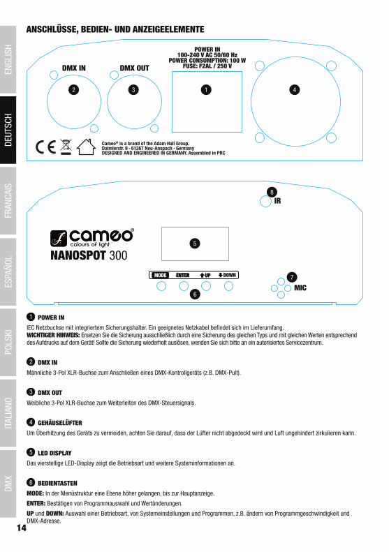
1 POWER IN
IEC power socket with built-in fuse holder. An appropriate power cord is included in the delivery. IMPORTANT INFORMATION: Always replace the fuse only with a fuse of the same type with the same rating (printed on the device). If the fuse blows repeatedly, please contact an authorised service centre.
2 DMX IN
3-pin male XLR socket for connection of a DMX controller (e.g. DMX console).
3 DMX OUT
3-pin female XLR socket for looping through the DMX control signal.
4 HOUSING FAN
To prevent overheating of the device, make sure that the fan is not covered and that air can circulate freely.
5 LED DISPLAY
The four-digit LED display indicates the operating mode and other system information.
6 CONTROL BUTTONS
MODE: To access a higher level in the menu structure and return to the main display.
ENTER: Confirm program selection and value changes.
UP and DOWN: Selecting an operating mode, system settings and programs, e.g. changing the program speed and DMX address.

6
DEUTSC
HFRAN
CAIS
ESPAÑO
LEN
GLISH
ITALIANO
POLSKI
DMX
7 MIC
Microphone for music control mode.
8 INFRARED SENSOR
In order to easily control the Moving Head via the supplied remote control, be sure to position the infrared interface of the remote control in direct visual contact, at a maximum distance of 5 m from the infrared interface of the spotlight.
NOTE: The lens for focussing the projection at different distances is located in the projection head of the Moving Head. The knurled frame provides for a better grip (clockwise rotation = remote range, counter-clockwise rotation = close range).
OPERATIONWhen the spotlight is properly connected to the mains, the motors are reset (Display = “InIt”). Within a few seconds, the spotlight is ready for use and changes to the mode that was previously selected.
SELECTING THE DMX STARTING ADDRESS AND DMX MODEPress the MODE button repeatedly until “dMX”, “PrEF”, “SLAV”, “Soun”, or “Auto” appears on the display. Now use the UP and DOWN but-tons to select the “dMX” menu item and confirm by pressing ENTER. “Add” now appears on the display and by pressing ENTER once more, you can select the DMX start address as desired using the UP and DOWN switches (A001 - A508). After confirming with ENTER, “SAVE” is briefly shown on the display. To set the DMX operating mode, select the menu item “dMX”, press ENTER and then use the UP and DOWN buttons to select the menu item “ChAn”. Press ENTER and use the UP and DOWN buttons to select the desired DMX mode (5Ch, 9Ch, 11Ch). After confirming with ENTER, “SAVE” is briefly shown on the display. The synchronous control of multiple spotlights (same model) through a DMX control unit (e.g. DMX console) can be achieved by assigning the spotlights to an identical DMX start address and DMX mode and connecting them using DMX cables.
UP/DOWN-> ENTER ->
<- MODEUP/DOWN –
-> ENTER ->
<- MODE
-> ENTER ->
<- MODEUP/DOWN / /
AUTOMATIC CONTROL MODE (AUTO)Select one of the 7 different Auto programs (Sh01 - Sh07) and their speed (SP00 - SP99). Press the MODE button repeatedly until “dMX”, “PrEF”, “SLAV”, “Soun”, or “Auto” appears on the display. Now use the UP and DOWN buttons to select the “Auto” menu item and confirm by pressing ENTER (“SAVE” is briefly displayed on the display). Press twice on ENTER, then use the UP and DOWN buttons to select one of the 7 Auto programs (the last 2 digits of the display will flash). After confirming with ENTER, “SAVE” is briefly shown on the display. Now the activated program will be shown on the display and you can use the UP and DOWN buttons to select the desired speed in the menu item. Now, press ENTER (the last two digits on the display will flash) and using the UP and DOWN buttons, select the speed from SP00 to SP99. After confirming with ENTER, “SAVE” is briefly displayed on the display.
UP/DOWN-> ENTER ->
<- MODE
–
-> ENTER ->
<- MODE
UP/DOWNENTER
UP/DOWN
–
MUSIC CONTROL (SOUND)Select the Music control mode, to control the Moving Head via the built-in microphone (bass pulses). Press the MODE button repeatedly until “dMX”, “PrEF”, “SLAV”, “Soun”, or “Auto” appears on the display. Now use the UP and DOWN buttons to select the “Soun” menu item and confirm by pressing ENTER (“SAVE” is briefly displayed on the display). Press ENTER again to select the sensitivity with which the spotlight responds to sounds (Su00 - Su99). After confirming with ENTER, “SAVE” is briefly shown on the display.
UP/DOWN-> ENTER ->
<- MODE
–
SLAVE MODEPress the MODE button repeatedly until “dMX”, “PrEF”, “SLAV”, “Soun”, or “Auto” appears on the display. Use the UP and DOWN buttons to select the “SLAV” menu item and confirm by pressing ENTER. Use the UP and DOWN buttons to select “YES” and confirm by pressing ENTER

ITALIANOPOLSKI
ESPAÑOLFRANCAIS
DEUTSCHENGLISH
7
DMX
(“SAVE” is briefly displayed on the display). Connect the slave and the master unit (same model) with a DMX cable and activate one of the standalone modes on the master unit. Now the slave unit follows the master unit.
SYSTEM SETTINGSTo adjust system settings, press the MODE button repeatedly until “dMX”, “PrEF”, “SLAV”, “Soun”, or “Auto” appears on the display. Use the UP and DOWN buttons to select the “PrEF” menu item and confirm by pressing ENTER. You can now select and adjust one of the following menu items using the UP and DOWN buttons (confirm with ENTER, exit with MODE):
UP/DOWN-> ENTER ->
<- MODEUP/DOWN /
-> ENTER ->
<- MODE
YES = LED displayIs rotated by180°(overhead mounting)
-> ENTER ->
<- MODEUP/DOWN /
YES = reversal of PAN direction
-> ENTER ->
<- MODEUP/DOWN /
YES = reversal of TILT direction
-> ENTER ->
<- MODEUP/DOWN /
on = display always onoff = display goes off after approx. 20 seconds of inactivity
With this menu item, you can definewhich operating mode should be enabledwhen in the DMX mode,the DMX signal is interrupted.
-> ENTER ->
<- MODEUP/DOWN
(blackout)
(last command)
(Music control)
IR REMOTE CONTROLIn order to easily control the Moving Head via the supplied remote control, be sure to position the infrared interface of the remote control in direct visual contact, at a maximum distance of 5 m from the infrared interface of the spotlight and follow the sequence of operations (1. “STAND BY”, 2. “FULL ON”).
STAND BY
Press on “STAND BY”, to control the Moving Head in the IR remote control mode. The LED display now shows “StoP” and the head moves in the upright position.
FULL ON
After the Moving Head has been brought into the IR remote control mode (see section “STAND BY”), press “FULL ON” to switch on the LED illumination.

8
DEUTSC
HFRAN
CAIS
ESPAÑO
LEN
GLISH
ITALIANO
POLSKI
DMX
GOBO
As soon as you press on “GOBO”, one of the 7 gobos plus open can now be selected using the number keys 1 to 8 (1 = open).
COLOR
As soon as you press on “COLOR”, one of the 7 colour filters plus open can now be selected using the number keys 1 to 8 (1 = open).
STROBE
To activate the stroboscope effect, press on “STROBE” and then select the speed of the strobe using the number keys 1 to 9 (1 = strobe disabled, 2 = slowest flash frequency, 9 = fastest flash frequency).
DIMMER+
Increase the brightness level by pressing “DIMMER+”.
DIMMER-
Decrease the brightness level by pressing “DIMMER-”.
1 - 9
The number keys 1 to 9 are used to select the different gobos, colour filters, strobe speed and internal programs.
SOUND ON
While one of the 7 internal show programs is selected, the Music control mode can be activated by pressing “SOUND ON”. Now the selected program is controlled via the built-in microphone and follows the beat of the music (bass pulses).
SOUND OFF
Press “SOUND OFF” to disable the Music control mode.
SHOW
Press “SHOW” to activate one of the 7 different Show programs using the number keys 1 to 7.
Press “STAND BY” to disable the IR remote control mode. The spotlight now changes to the mode that was previously selected.
SETTING UP AND MOUNTINGThanks to the integrated rubber feet, the spotlight can be placed in a suitable location on the stage floor etc.
Mounting on a truss is performed with the help of the supplied omega mounting bracket; secure the device with a suitable safety rope to
the safety screw eye. Fix both firmly onto the base plate of the spotlight, suitable screws are included in the delivery. NOTE: Overhead installation should only be carried out by trained personnel.

ITALIANOPOLSKI
ESPAÑOLFRANCAIS
DEUTSCHENGLISH
9
DMX
DMX TECHNOLOGY
DMX-512DMX (Digital Multiplex) is the designation for a universal transmission protocol for communications between corresponding devices and controllers. A DMX controller sends DMX data to the connected DMX device(s). The DMX data is always transmitted as a serial data stream that is forwarded from one connected device to the next via the "DMX IN" and "DMX OUT" connectors (XLR plug-type connectors) that are found on every DMX-capable device, provided the maximum number of devices does not exceed 32 units. The last device in the chain needs to be equipped with a terminator (terminating resistor).
DMX CONNECTIONDMX is the common "language" via which a very wide range of types and models of equipment from various manufacturers can be connected with one another and controlled via a central controller, provided that all of the devices and the controller are DMX compatible. For optimum data transmission, it is necessary to keep the connecting cables between the individual devices as short as possible. The order in which the devices are integrated in the DMX network has no influence on the addresses. Thus the device with the DMX address 1 can be located at any position in the (serial) DMX chain: at the beginning, at the end or somewhere in the middle. If the DMX address 1 is assigned to a device, the controller "knows" that it should send all data allocated to address 1 to this device regardless of its position in the DMX network.
SERIAL CONNECTION OF MULTIPLE LIGHTS1. Connect the male XLR connector (3-pin or 5-pin) of the DMX cable to the DMX output (female XLR socket) of the first DMX device (e.g. DMX-Controller).2. Connect the female 3-pin XLR connector of the DMX cable connected to the first projector to the DMX input (male 3-pin socket) of the next DMX device. In the same way, connect the DMX output of this device to the DMX input of the next device and repeat until all devices have been connected. Please note that as a rule, DMX devices are connected in series and connections cannot be shared without active splitters. The maximum number of DMX devices in a DMX chain should not exceed 32 units.
The Adam Hall 3 STAR, 4 STAR, and 5 STAR product ranges include an extensive selection of suitable cables.
DMX CABLESWhen fabricating your own cables, always observe the illustrations on this page. Never connect the shielding of the cable to the ground contact of the plug, and always make certain that the shielding does not come into contact with the housing of the XLR plug. If the shielding is connected to the ground, this can lead to short-circuiting and system malfunctions.
Pin AssignmentDMX cable with 3-pin XLR connectors: DMX cable with 5-pin XLR connectors (pin 4 and 5 are not used):
Shield
23
1
23
1
123
45
12
34
5
Shield
DMX TERMINATORS (TERMINATING RESISTORS)To prevent system errors, the last device in a DMX chain needs to be equipped with a terminating resistor (120 ohm, 1/4 Watt).3-pin XLR connector with a terminating resistor: K3DMXT35-pin XLR connector with a terminating resistor: K3DMXT5
Pin Assignment3-pin XLR connector: 5-pin XLR connector:
23
1
12
34
5
DMX ADAPTERThe combination of DMX devices with 3-pin connectors and DMX devices with 5-pin connectors in a DMX chain is possible with suitable adapters.
Pin AssignmentDMX Adapter 5-pin XLR male to 3-pin XLR female: K3DGF0020Pins 4 and 5 are not used.
Pin AssignmentDMX Adapter 3-pin XLR male to 5-pin XLR female: K3DHM0020Pins 4 and 5 are not used.

10
DEUTSC
HFRAN
CAIS
ESPAÑO
LEN
GLISH
ITALIANO
POLSKI
DMX
TECHNICAL SPECIFICATIONSModel Name: CLNS300
Product Type: LED moving head
Type: spot
Colour Spectrum: W
Number of LEDs: 1
LED Type: 30 W
Beam Angle: 13°
DMX Input: 3-pin XLR male
DMX Output: 3-pin XLR female
DMX Mode: 5-channel, 9-channel, 11-channel
DMX Functions: Pan/Tilt, Pan/Tilt fine, Colour Wheel, Gobo Wheel, Motor Speed, Auto Programs, Music Control, Stroboscope, Dimmer
Standalone Functions: Auto Programs, Music Control, Master/Slave mode
Control: DMX512, IR remote control
Controls: Mode, Enter, Up, Down
Indicators: 4-digit LED display
PAN Angle: 540°
TILT Angle: 230°
Operating Voltage: 100 - 240 V AC / 50 - 60 Hz
Power Consumption: 100 W
Light Output: 650 lm
Illuminance (@ 1 m): 24,500 lx
Power Connector: IEC power socket
Fuse: F2AL / 250 V fuse (5 x 20 mm).
Temperature (during operation): 0°C - 40°C
Relative Humidity: < 85% non-condensing
Housing Material: metal, ABS
Housing Colour: black
Housing Cooling: fan
Dimensions (W x H x D, excluding bracket): 165 x 280 x 155 mm
Weight: 3 kg
Other Features: power cable, IR remote control, safety screw eye and omega mounting bracket included

ITALIANOPOLSKI
ESPAÑOLFRANCAIS
DEUTSCHENGLISH
11
DMX
MANUFACTURER´S DECLARATIONS
MANUFACTURER‘S WARRANTY & LIMITATIONS OF LIABILITY You can find our current warranty conditions and limitations of liability at: http://www.adamhall.com/media/shop/downloads/documents/manufacturersdeclarations.pdf. To request warranty service for a product, please contact Adam Hall GmbH, Daimler Straße 9, 61267 Neu Anspach / Email: [email protected] / +49 (0)6081 / 9419-0.
CORRECT DISPOSAL OF THIS PRODUCT(valid in the European Union and other European countries with a differentiated waste collection system) This symbol on the product, or on its documents indicates that the device may not be treated as household waste. This is to avoid
environmental damage or personal injury due to uncontrolled waste disposal. Please dispose of this product separately from other waste and have it recycled to promote sustainable economic activity. Household users should contact either the retailer where they purchased this product, or their local government office, for details on where and how they can recycle this item in an environmentally friendly manner. Business users should contact their supplier and check the terms and conditions of the purchase contract. This product should not be mixed with other commercial waste for disposal.
CE ComplianceAdam Hall GmbH states that this product meets the following guidelines (where applicable):R&TTE (1999/5/EC) or RED (2014/53/EU) from June 2017Low voltage directive (2014/35/EU)EMV directive (2014/30/EU)RoHS (2011/65/EU)The complete declaration of conformity can be found at www.adamhall.com. Furthermore, you may also direct your enquiry to [email protected].

12
DEUTSC
HFRAN
CAIS
ESPAÑO
LEN
GLISH
ITALIANO
POLSKI
DMX
DEUTSCH
SIE HABEN DIE RICHTIGE WAHL GETROFFEN!Dieses Gerät wurde unter hohen Qualitätsanforderungen entwickelt und gefertigt, um viele Jahre einen reibungslosen Betrieb zu gewähr-leisten. Bitte lesen Sie diese Bedienungsanleitung sorgfältig, damit Sie Ihr neues Produkt von Cameo Light schnell und optimal einsetzen können. Weitere Informationen über Cameo Light erhalten Sie auf unserer Website WWW.CAMEOLIGHT.COM.
SICHERHEITSHINWEISE 1. Lesen Sie diese Anleitung bitte sorgfältig durch. 2. Bewahren Sie alle Informationen und Anleitungen an einem sicheren Ort auf. 3. Befolgen Sie die Anweisungen. 4. Beachten Sie alle Warnhinweise. Entfernen Sie keine Sicherheitshinweise oder andere Informationen vom Gerät. 5. Verwenden Sie das Gerät nur in der vorgesehenen Art und Weise. 6. Verwenden Sie ausschließlich stabile und passende Stative bzw. Befestigungen (bei Festinstallationen). Stellen Sie sicher, dass Wandhalterungen ordnungsgemäß installiert und gesichert sind. Stellen Sie sicher, dass das Gerät sicher installiert ist und nicht herunterfallen kann. 7. Beachten Sie bei der Installation die für Ihr Land geltenden Sicherheitsvorschriften. 8. Installieren und betreiben Sie das Gerät nicht in der Nähe von Heizkörpern, Wärmespeichern, Öfen oder sonstigen Wärmequellen. Sorgen Sie dafür, dass das Gerät immer so installiert ist, dass es ausreichend gekühlt wird und nicht überhitzen kann. 9. Platzieren Sie keine Zündquellen wie z.B. brennende Kerzen auf dem Gerät. 10. Lüftungsschlitze dürfen nicht blockiert werden.11. Das Gerät wurde ausschließlich für die Verwendung in Innenräumen entwickelt, betreiben Sie das Gerät nicht in unmittelbarer Nähe von Wasser (gilt nicht für spezielle Outdoor Geräte - beachten Sie in diesem Fall bitte die im Folgenden vermerkten Sonderhinweise). Bringen Sie das Gerät nicht mit brennbaren Materialien, Flüssigkeiten oder Gasen in Berührung.12. Sorgen Sie dafür, dass kein Tropf- oder Spritzwasser in das Gerät eindringen kann. Stellen Sie keine mit Flüssigkeit gefüllten Behältnisse wie Vasen oder Trinkgefäße auf das Gerät. 13. Sorgen Sie dafür, dass keine Gegenstände in das Gerät fallen können. 14. Betreiben Sie das Gerät nur mit dem vom Hersteller empfohlenen und vorgesehenen Zubehör. 15. Öffnen Sie das Gerät nicht und verändern Sie es nicht. 16. Überprüfen Sie nach dem Anschluss des Geräts alle Kabelwege, um Schäden oder Unfälle, z. B. durch Stolperfallen zu vermeiden. 17. Achten Sie beim Transport darauf, dass das Gerät nicht herunterfallen und dabei möglicherweise Sach- und Personenschäden verursachen kann.18. Wenn Ihr Gerät nicht mehr ordnungsgemäß funktioniert, Flüssigkeiten oder Gegenstände in das Geräteinnere gelangt sind, oder das Gerät anderweitig beschädigt wurde, schalten Sie es sofort aus und trennen es von der Netzsteckdose (sofern es sich um ein aktives Gerät handelt). Dieses Gerät darf nur von autorisiertem Fachpersonal repariert werden. 19. Verwenden Sie zur Reinigung des Geräts ein trockenes Tuch. 20. Beachten Sie alle in Ihrem Land geltenden Entsorgungsgesetze. Trennen Sie bei der Entsorgung der Verpackung bitte Kunststoff und Papier bzw. Kartonagen voneinander. 21. Kunststoffbeutel müssen außer Reichweite von Kindern aufbewahrt werden.
BEI GERÄTEN MIT NETZANSCHLUSS:22. ACHTUNG: Wenn das Netzkabel des Geräts mit einem Schutzkontakt ausgestattet ist, muss es an einer Steckdose mit Schutzleiter angeschlossen werden. Deaktivieren Sie niemals den Schutzleiter eines Netzkabels. 23. Schalten Sie das Gerät nicht sofort ein, wenn es starken Temperaturschwankungen ausgesetzt war (beispielsweise nach dem Transport). Feuchtigkeit und Kondensat könnten das Gerät beschädigen. Schalten Sie das Gerät erst ein, wenn es Zimmertemperatur erreicht hat. 24. Bevor Sie das Gerät an die Steckdose anschließen, prüfen Sie zuerst, ob die Spannung und die Frequenz des Stromnetzes mit den auf dem Gerät angegebenen Werten übereinstimmen. Verfügt das Gerät über einen Spannungswahlschalter, schließen Sie das Gerät nur an die Steckdose an, wenn die Gerätewerte mit den Werten des Stromnetzes übereinstimmen. Wenn das mitgelieferte Netzkabel bzw. der mitgelie-ferte Netzadapter nicht in Ihre Netzsteckdose passt, wenden Sie sich an Ihren Elektriker. 25. Treten Sie nicht auf das Netzkabel. Sorgen Sie dafür, dass spannungsführende Kabel speziell an der Netzbuchse bzw. am Netzadapter und der Gerätebuchse nicht geknickt werden. 26. Achten Sie bei der Verkabelung des Geräts immer darauf, dass das Netzkabel bzw. der Netzadapter stets frei zugänglich ist. Trennen Sie das Gerät stets von der Stromzuführung, wenn das Gerät nicht benutzt wird, oder Sie das Gerät reinigen möchten. Ziehen Sie Netzkabel und Netzadapter immer am Stecker bzw. am Adapter und nicht am Kabel aus der Steckdose. Berühren Sie Netzkabel und Netzadapter niemals mit nassen Händen. 27. Schalten Sie das Gerät möglichst nicht schnell hintereinander ein und aus, da sonst die Lebensdauer des Geräts beeinträchtigt werden könnte.28. WICHTIGER HINWEIS: Ersetzen Sie Sicherungen ausschließlich durch Sicherungen des gleichen Typs und Wertes. Sollte eine Sicherung wiederholt auslösen, wenden Sie sich bitte an ein autorisiertes Servicezentrum. 29. Um das Gerät vollständig vom Stromnetz zu trennen, entfernen Sie das Netzkabel bzw. den Netzadapter aus der Steckdose. 30. Wenn Ihr Gerät mit einem Volex-Netzanschluss bestückt ist, muss der passende Volex-Gerätestecker entsperrt werden, bevor er entfernt werden kann. Das bedeutet aber auch, dass das Gerät durch ein Ziehen am Netzkabel verrutschen und herunterfallen kann, wodurch Perso-nen verletzt werden und/oder andere Schäden auftreten können. Verlegen Sie Ihre Kabel daher immer sorgfältig. 31. Entfernen Sie Netzkabel und Netzadapter aus der Steckdose bei Gefahr eines Blitzschlags oder wenn Sie das Gerät länger nicht verwenden.32. Das Gerät darf nur im spannungsfreien Zustand (Trennung des Netzsteckers vom Stromnetz) installiert werden.33. Staub und andere Ablagerungen im Inneren des Geräts können es beschädigen. Das Gerät sollte je nach Umgebungsbedingungen (Staub, Nikotin, Nebel etc.) regelmäßig von qualifiziertem Fachpersonal gewartet bzw. gesäubert werden (keine Garantieleistung), um Überhitzung und Fehlfunktionen zu vermeiden.34. Der Abstand zu brennbaren Materialien muss mindestens 0,5 m betragen.35. Netzleitungen zur Spannungsversorgung mehrerer Geräte müssen mindestens 1,5 mm² Aderquerschnitt aufweisen. In der EU müssen

ITALIANOPOLSKI
ESPAÑOLFRANCAIS
DEUTSCHENGLISH
13
DMX
die Leitungen H05VV-F, oder gleichartig, entsprechen. Geeignete Leitungen werden von Adam Hall angeboten. Mit diesen Leitungen können Sie mehrere Geräte über den Power out Anschluss mit dem Power IN Anschluss eines weiteren Gerätes verbinden. Beachten Sie, dass die gesamte Stromaufnahme aller angeschlossenen Geräte den vorgegebenen Wert nicht überschreitet (Aufdruck auf dem Gerät). Achten Sie darauf, Netzleitungen so kurz wie möglich zu halten.
ACHTUNGEntfernen Sie niemals die Abdeckung, da sonst das Risiko eines elektrischen Schlages besteht. Im Inneren des Geräts befinden sich keine Teile, die vom Bediener repariert oder gewartet werden können. Lassen Sie Wartung und Reparaturen ausschließlich von qualifiziertem Servicepersonal durchführen.
Das gleichseitige Dreieck mit Blitzsymbol warnt vor nichtisolierten, gefährlichen Spannungen im Geräteinneren, die einen elektrischen Schlag verursachen können.
Das gleichseitige Dreieck mit Ausrufungszeichen kennzeichnet wichtige Bedienungs- und Wartungshinweise.
Warnung! Dieses Symbol kennzeichnet heiße Oberflächen. Während des Betriebs können bestimmte Teile des Gehäuses heiß werden. Berühren oder transportieren Sie das Gerät nach einem Einsatz erst nach einer Abkühlzeit von mindestens 10 Minuten.
Warnung! Dieses Gerät ist für eine Nutzung bis zu einer Höhe von maximal 2000 Metern über dem Meeresspiegel bestimmt.
Warnung! Dieses Gerät ist nicht für den Einsatz in tropischen Klimazonen bestimmt.
VORSICHT! WICHTIGE HINWEISE IN BEZUG AUF LICHT-PRODUKTE!1. Das Produkt ist für den professionellen Einsatz im Bereich der Veranstaltungstechnik entwickelt worden und ist nicht für die Raumbeleuchtung in Haushalten geeignet.2. Blicken Sie niemals, auch nicht kurzzeitig, direkt in den Lichtstrahl. 3. Blicken Sie niemals mit optischen Geräten wie Vergrößerungsgläsern in den Lichtstrahl.4. Stroboskopeffekte können unter Umständen bei empfindlichen Menschen epileptische Anfälle auslösen! Epilepsiekranke Menschen sollten daher unbedingt Orte meiden, an denen Stroboskope eingesetzt werden.
EINFÜHRUNGMINI MOVING HEAD 30W
CLNS300
STEUERUNGSFUNKTIONEN
5-Kanal, 9-Kanal, 11-Kanal DMX-Steuerung
IR-Fernbedienung
Master / Slave Betrieb
Standalone Funktion
EIGENSCHAFTEN
Mini Moving Head mit 30W CW LED, Farbrad mit 7 Farben plus offen, Goborad mit 7 Gobos plus offen, 540° PAN und 230° TILT Bewegung, 3 DMX-Modi, DMX-512 Steuerung, Master / Slave Betrieb, Standalone Programme, Musiksteuerung über eingebautes Mikrofon, Universelle Montagemöglichkeiten, Gummifüße, Safety Schrauböse und 1 Omega-Bügel inklusive, Betriebsspannung 100V - 240V AC / 50 - 60Hz, Leistungsaufnahme 100W.
BEDIENUNG
Der Cameo NANOSPOT300 ist ein DMX-512-steuerbarer Mini LED Moving Head und läßt sich als Standalone-Gerät, im Master / Slave-Betrieb, per IR-Fernbedienung und Musiksteuerung betreiben.
14
DEUTSC
HFRAN
CAIS
ESPAÑO
LEN
GLISH
ITALIANO
POLSKI
DMX
ANSCHLÜSSE, BEDIEN- UND ANZEIGEELEMENTE
2 3 1 4
5
6
7
8
1 POWER IN
IEC Netzbuchse mit integriertem Sicherungshalter. Ein geeignetes Netzkabel befindet sich im Lieferumfang. WICHTIGER HINWEIS: Ersetzen Sie die Sicherung ausschließlich durch eine Sicherung des gleichen Typs und mit gleichen Werten entsprechend des Aufdrucks auf dem Gerät! Sollte die Sicherung wiederholt auslösen, wenden Sie sich bitte an ein autorisiertes Servicezentrum.
2 DMX IN
Männliche 3-Pol XLR-Buchse zum Anschließen eines DMX-Kontrollgeräts (z.B. DMX-Pult).
3 DMX OUT
Weibliche 3-Pol XLR-Buchse zum Weiterleiten des DMX-Steuersignals.
4 GEHÄUSELÜFTER
Um Überhitzung des Geräts zu vermeiden, achten Sie darauf, dass der Lüfter nicht abgedeckt wird und Luft ungehindert zirkulieren kann.
5 LED DISPLAY
Das vierstellige LED-Display zeigt die Betriebsart und weitere Systeminformationen an.
6 BEDIENTASTEN
MODE: In der Menüstruktur eine Ebene höher gelangen, bis zur Hauptanzeige.
ENTER: Bestätigen von Programmauswahl und Wertänderungen.
UP und DOWN: Auswahl einer Betriebsart, von Systemeinstellungen und Programmen, z.B. ändern von Programmgeschwindigkeit und DMX-Adresse.

ITALIANOPOLSKI
ESPAÑOLFRANCAIS
DEUTSCHENGLISH
15
DMX
7 MIC
Mikrofon für die Betriebsart Musiksteuerung.
8 INFRAROTSENSOR
Um den Moving Head bequem über die mitgelieferte IR-Fernbedienung steuern zu können, achten Sie darauf, die Infrarot-Schnittstelle der Fernbedienung in direktem Sichtkontakt in einem Abstand von bis zu ca. 5m zur Infrarot-Schnittstelle des Scheinwerfers zu positionieren.
HINWEIS: Im Projektionskopf des Moving Heads befindet sich die Linse zum Fokussieren der Projektion in unterschiedlichen Entfernungen. Für eine verbesserte Griffigkeit sorgt eine gerändelte Fassung (Drehung im Uhrzeigersinn = Fernbereich, Drehung gegen den Uhrzeigersinn = Nahbereich).
BEDIENUNGSobald der Scheinwerfer korrekt am Stromnetz angeschlossen ist, erfolgt das Zurücksetzen der Motoren (Display = „InIt“). Nach wenigen Sekunden ist der Scheinwerfer betriebsbereit und wechselt in die Betriebsart, die zuvor angewählt war.
DMX-STARTADRESSE UND DMX-BETRIEBSART EINSTELLENDrücken Sie die MODE-Taste so oft, bis im Display einer der Menüpunkte „dMX“, „PrEF“, „SLAV“, „Soun“, oder „Auto“ angezeigt wird. Wählen Sie nun mit Hilfe der Tasten UP und DOWN den Menüpunkt „dMX“ aus und drücken auf ENTER. Im Display wird jetzt „Add“ angezeigt und Sie können durch nochmaliges Drücken auf ENTER die DMX-Startadresse anzeigen lassen und sie mit Hilfe der Tasten UP und DOWN wunschge-mäß einstellen (A001 - A508). Nach dem Bestätigen mit ENTER wird im Display für kurze Zeit „SAVE“ angezeigt. Die DMX-Betriebsart stellen Sie ein, indem Sie den Menüpunkt „dMX“ auswählen, auf ENTER drücken und nun mit UP und DOWN den Menüpunkt „ChAn“ auswählen. Drücken Sie auf ENTER und wählen nun mit Hilfe der Tasten UP und DOWN die gewünschte DMX-Betriebsart aus (5Ch, 9Ch, 11Ch). Nach dem Bestätigen mit ENTER wird im Display für kurze Zeit „SAVE“ angezeigt. Die synchrone Ansteuerung mehrerer Scheinwerfer des gleichen Modells durch ein DMX-Steuergerät (z.B. DMX-Pult) erreichen Sie, indem Sie die Scheinwerfer auf eine identische DMX-Startadresse und die gleiche DMX-Betriebsart einstellen und mit Hilfe von DMX-Kabeln verbinden.
UP/DOWN-> ENTER ->
<- MODEUP/DOWN –
-> ENTER ->
<- MODE
-> ENTER ->
<- MODEUP/DOWN / /
AUTOMATISCHE STEUERUNG (AUTO)Wählen Sie eines der 7 verschiedenen Auto-Programme (Sh01 - Sh07) und deren Laufgeschwindigkeit aus (SP00 - SP99). Drücken Sie die MODE-Taste so oft, bis im Display einer der Menüpunkte „dMX“, „PrEF“, „SLAV“, „Soun“, oder „Auto“ angezeigt wird. Wählen Sie nun mit Hilfe der Tasten UP und DOWN den Menüpunkt „Auto“ aus und drücken auf ENTER (im Display wird für kurze Zeit „SAVE“ angezeigt). Drücken Sie zwei mal auf ENTER, um nun mit Hilfe der Tasten UP und DOWN aus den 7 Auto-Programmen wählen zu können (die letzten 2 Ziffern des Displays blinken). Nach dem Bestätigen mit ENTER wird im Display für kurze Zeit „SAVE“ angezeigt. Nun wird im Display das aktivierte Programm angezeigt und Sie können mit Hilfe der Tasten UP und DOWN den Menüpunkt für die Laufgeschwindigkeit auswählen. Drücken Sie auf ENTER (die letzten 2 Ziffern des Displays blinken) und stellen die Geschwindigkeit mit Hilfe der Tasten UP und DOWN von SP00 bis SP99 ein. Nach dem Bestätigen mit ENTER, wird im Display für kurze Zeit „SAVE“ angezeigt.
UP/DOWN-> ENTER ->
<- MODE
–
-> ENTER ->
<- MODE
UP/DOWNENTER
UP/DOWN
–
MUSIKSTEUERUNG (SOUND)Wählen Sie die Betriebsart Musiksteuerung, um den Moving Head über das integrierte Mikrofon steuern zu lassen (Bassimpulse). Drücken Sie die MODE-Taste so oft, bis im Display einer der Menüpunkte „dMX“, „PrEF“, „SLAV“, „Soun“, oder „Auto“ angezeigt wird. Wählen Sie nun mit Hilfe der Tasten UP und DOWN den Menüpunkt „Soun“ aus und drücken auf ENTER (im Display wird für kurze Zeit „SAVE“ angezeigt). Drücken Sie abermals auf ENTER, um die Empfindlichkeit, mit der der Scheinwerfer auf Geräusche reagieren soll, wunschgemäß einzustellen (Su00 - Su99). Nach dem Bestätigen mit ENTER wird im Display für kurze Zeit „SAVE“ angezeigt.
UP/DOWN-> ENTER ->
<- MODE
–

16
DEUTSC
HFRAN
CAIS
ESPAÑO
LEN
GLISH
ITALIANO
POLSKI
DMX
SLAVE-BETRIEBDrücken Sie die MODE-Taste so oft, bis im Display einer der Menüpunkte „dMX“, „PrEF“, „SLAV“, „Soun“, oder „Auto“ angezeigt wird. Wählen Sie mit Hilfe der Tasten UP und DOWN den Menüpunkt „SLAV“ aus und drücken auf ENTER. Nutzen Sie die Tasten UP und DOWN um nun „YES“ auszuwählen und bestätigen mit ENTER (im Display wird für kurze Zeit „SAVE“ angezeigt). Verbinden Sie die Slave- und die Master-Einheit (gleiches Modell) mit Hilfe eines DMX-Kabels und aktivieren in der Master-Einheit eine der Standalone Betriebsarten. Nun folgt die Slave-Einheit der Master-Einheit.
SYSTEMEINSTELLUNGENUm Systemeinstellungen vornehmen zu können, drücken Sie die MODE-Taste so oft, bis im Display einer der Menüpunkte „dMX“, „PrEF“, „SLAV“, „Soun“, oder „Auto“ angezeigt wird. Wählen Sie mit Hilfe der Tasten UP und DOWN den Menüpunkt „PrEF“ aus und drücken auf ENTER. Sie können nun mit Hilfe der UP und DOWN Tasten einen der folgenden Menüpunkte auswählen und bearbeiten (bestätigen mit ENTER, verlassen mit MODE):
UP/DOWN-> ENTER ->
<- MODEUP/DOWN /
-> ENTER ->
<- MODE
YES = Display-Anzeigewird um 180° gedreht(Überkopf-Montage)
-> ENTER ->
<- MODEUP/DOWN /
YES = Umkehrung der PAN Bewegungsrichtung
-> ENTER ->
<- MODEUP/DOWN /
YES = Umkehrung der TILT Bewegungsrichtung
-> ENTER ->
<- MODEUP/DOWN /
on = Display permanent anoff = Display erlischt nach ca. 20 Sekunden Inaktivität
Mit Hilfe dieses Menüpunktes definierenSie, welcher Betriebszustand aktiviertwerden soll, wenn in der DMX-Betriebsartdas DMX-Signal unterbrochen wird.
-> ENTER ->
<- MODEUP/DOWN
(blackout)
(letzter DMX-Befehl)
(Musiksteuerung)
IR FERNBEDIENUNGUm den Moving Head bequem über die mitgelieferte IR-Fernbedienung steuern zu können, achten Sie darauf, die Infrarot-Schnittstelle der Fernbedienung in direktem Sichtkontakt in einem Abstand von bis zu ca. 5m zur Infrarot-Schnittstelle des Scheinwerfers zu positionieren und befolgen bitte die Reihenfolge der Bedienschritte (1. „STAND BY“, 2. „FULL ON“).
STAND BY
Drücken Sie auf „STAND BY“, um den Moving Head in die Betriebsart IR-Fernsteuerung zu bringen. Das LED-Display zeigt nun „StoP“ und der Kopf bewegt sich in die aufrechte Position.
FULL ON
Nachdem der Moving Head in die Betriebsart IR-Fernsteuerung gebracht wurde (siehe Punkt „STAND BY“), drücken Sie auf „FULL ON“, um die Beleuchtungs-LED einzuschalten.

ITALIANOPOLSKI
ESPAÑOLFRANCAIS
DEUTSCHENGLISH
17
DMX
GOBO
Sobald Sie auf „GOBO“ drücken, kann nun eines der 7 Gobos plus offen mit Hilfe der Nummerntasten 1 bis 8 ausgewählt werden (1 = offen).
COLOR
Drücken Sie auf „COLOR“, um einen der 7 Farbfilter plus offen mit Hilfe der Nummerntasten 1 bis 8 auszuwählen (1 = offen).
STROBE
Zum aktivieren des Stroboskop-Effekts drücken Sie auf „STROBE“ und wählen dann mit Hilfe der Nummerntasten 1 bis 9 die Stroboskop-Geschwindigkeit aus (1 = Stroboskop deaktiviert, 2 = langsamste Blitzfrequenz, 9 = schnellste Blitzfrequenz).
DIMMER+
Erhöhen Sie die Helligkeit, indem Sie auf „DIMMER+“ drücken.
DIMMER-
Verringern Sie die Helligkeit, indem Sie auf „DIMMER-“ drücken.
1 - 9
Die Nummerntasten 1 bis 9 dienen dazu, die verschiedenen Gobos, die Farbfilter, die Stroboskop-Geschwindigkeit und die internen Programme auszuwählen.
SOUND ON
Während eines der 7 internen Show-Programme ausgewählt ist, kann durch Drücken auf „SOUND ON“ die Betriebsart Musiksteuerung aktiviert werden. Das ausgewählte Programm wird nun über das eingebaute Mikrofon gesteuert und folgt dem Takt der Musik (Bassimpulse).
SOUND OFF
Zum Deaktivieren der Betriebsart Musiksteuerung, drücken Sie auf „SOUND OFF“.
SHOW
Drücken Sie auf „SHOW“, um eines der 7 verschiedenen Show-Programme mit Hilfe der Nummerntasten 1 bis 7 zu aktivieren.
Zum Verlassen der Betriebsart IR-Fernbedienung, drücken Sie abermals auf „STAND BY“. Der Scheinwerfer wechselt nun in die Betriebsart, die zuvor aktiviert war.
AUFSTELLUNG UND MONTAGEDank der integrierten Gummifüße kann der Scheinwerfer an einer geeigneten Stelle auf den Bühnenboden etc. gestellt werden.
Die Montage an einer Traverse erfolgt mit Hilfe des mitgelieferten Omega-Bügels, sichern Sie das Gerät mit einem geeigneten Sicherungsseil an der Safety Schrauböse. Befestigen Sie Beides fest an der Bodenplatte des Scheinwerfers, geeignete Schrauben befinden sich im Lieferumfang. Hinweis: Überkopfmontage darf nur von dafür ausgebildetem Personal durchgeführt werden.

18
DEUTSC
HFRAN
CAIS
ESPAÑO
LEN
GLISH
ITALIANO
POLSKI
DMX
DMX TECHNIK
DMX-512DMX (Digital Multiplex) ist die Bezeichnung für ein universelles Übertragungsprotokoll für die Kommunikation zwischen entsprechenden Geräten und Controllern. Ein DMX-Controller sendet DMX-Daten an das/die angeschlossene(n) DMX-Gerät(e). Die DMX-Datenübertragung erfolgt stets als serieller Datenstrom, der über die an jedem DMX-fähigen Gerät vorhandenen DMX IN- und DMX OUT-Anschlüsse (XLR-Steckverbinder) von einem angeschlossenen Gerät an das nächste weitergeleitet wird, wobei die maximale Anzahl der Geräte 32 nicht überschreiten darf. Das letzte Gerät der Kette ist mit einem Abschlussstecker (Terminator) zu bestücken.
DMX-VERBINDUNG:DMX ist die gemeinsame "Sprache", über die sich die unterschiedlichsten Gerätetypen und Modelle verschiedener Hersteller miteinander verkoppeln und über einen zentralen Controller steuern lassen, sofern sämtliche Geräte und der Controller DMX-kompatibel sind. Für eine optimale Datenübertragung ist es erforderlich, die Verbindungskabel zwischen den einzelnen Geräten so kurz wie möglich zu halten. Die Reihenfolge, in der die Geräte in das DMX-Netzwerk eingebunden sind, hat keinen Einfluss auf die Adressierung. So kann sich das Gerät mit der DMX-Adresse 1 an einer beliebigen Position in der (seriellen) DMX-Kette befinden, am Anfang, am Ende oder irgendwo in der Mitte. Wird einem Gerät die DMX-Adresse 1 zugewiesen, "weiß" der Controller, dass er alle der Adresse 1 zugeordneten Daten an dieses Gerät senden soll, ungeachtet seiner Position im DMX-Verbund.
SERIELLE VERKOPPLUNG MEHRERER SCHEINWERFER1. Verbinden Sie den männlichen XLR-Stecker (3-Pol oder 5-Pol) des DMX-Kabels mit dem DMX-Ausgang (weibliche XLR-Buchse) des ersten DMX-Geräts (z.B. DMX-Controller).2. Verbinden Sie den weibliche XLR-Stecker des an den ersten Scheinwerfer angeschlossenen DMX-Kabels mit dem DMX-Eingang (männliche XLR-Buchse) des nächsten DMX-Geräts. Verbinden Sie den DMX-Ausgang dieses Geräts in der gleichen Weise mit dem DMX-Eingang des nächsten Geräts und so weiter. Bitte beachten Sie, dass DMX-Geräte grundsätzlich seriell verschaltet werden und die Verbindungen nicht ohne aktiven Splitter geteilt werden können. Die maximale Anzahl der DMX-Geräte einer DMX-Kette darf 32 nicht überschreiten.
Eine umfangreiche Auswahl geeigneter DMX-Kabel finden Sie in den Adam Hall Produktlinien 3 STAR, 4 STAR und 5 STAR.
DMX-KABEL:Beachten Sie bei der Anfertigung eigener Kabel unbedingt die Abbildungen auf dieser Seite. Verbinden Sie auf keinen Fall die Abschirmung des Kabels mit dem Massekontakt des Steckers, und achten Sie darauf, dass die Abschirmung nicht mit dem XLR-Steckergehäuse in Kontakt kommt. Hat die Abschirmung Massekontakt, kann dies zu Systemfehlern führen.
Steckerbelegung:DMX-Kabel mit 3-Pol XLR-Steckern: DMX-Kabel mit 5-Pol XLR-Steckern (Pin 4 und 5 sind nicht belegt.):
Shield
23
1
23
1
123
45
12
34
5
Shield
DMX-ABSCHLUSSSTECKER (TERMINATOR):Um Systemfehler zu vermeiden, ist das letzte Gerät einer DMX-Kette mit einem Abschlusswiderstand zu bestücken (120 Ohm, 1/4 Watt).3-Pol XLR-Stecker mit Abschlusswiderstand: K3DMXT35-Pol XLR-Stecker mit Abschlusswiderstand: K3DMXT5
Steckerbelegung:3-Pol XLR-Stecker: 5-Pol XLR-Stecker:
23
1
12
34
5
DMX-ADAPTER:Die Kombination von DMX-Geräten mit 3-Pol Anschlüssen und DMX-Geräten mit 5-Pol Anschlüssen in einer DMX-Kette ist mit Hilfe von Adaptern ebenso möglich.
SteckerbelegungDMX-Adapter 5-Pol XLR male auf 3-Pol XLR female: K3DGF0020Pin 4 und 5 sind nicht belegt.
SteckerbelegungDMX-Adapter 3-Pol XLR male auf 5-Pol XLR female: K3DHM0020Pin 4 und 5 sind nicht belegt.

ITALIANOPOLSKI
ESPAÑOLFRANCAIS
DEUTSCHENGLISH
19
DMX
TECHNISCHE DATENModellbezeichnung: CLNS300
Produktart: LED Moving Head
Typ: Spot
Farbspektrum: W
LED Anzahl: 1
LED Typ: 30 W
Abstrahlwinkel: 13°
DMX-Eingang: 3-Pol XLR männlich
DMX-Ausgang: 3-Pol XLR weiblich
DMX-Modus: 5-Kanal, 9-Kanal, 11-Kanal
DMX Funktionen: Pan/Tilt, Pan/Tilt fein, Farbrad, Goborad, Motor Geschwindigkeit, Auto Programme, Musiksteuerung, Stroboskop, Dimmer
Standalone Funktionen: Auto Programme, Musiksteuerung, Master/Slave-Betrieb
Steuerung: DMX512, IR Fernbedienung
Bedienelemente: Mode, Enter, Up, Down
Anzeigeelemente: 4-stelliges LED Display
PAN Winkel: 540°
TILT Winkel: 230°
Betriebsspannung: 100 - 240 V AC / 50 - 60 Hz
Leistungsaufnahme: 100 W
Lichtstrom: 650 lm
Beleuchtungsstärke (@ 1m): 24500 lx
Stromversorgungsanschluss: IEC Netzbuchse
Sicherung: F2AL / 250V (5 x 20 mm)
Umgebungsstemperatur (in Betrieb): 0°C - 40°C
Relative Luftfeuchtigkeit: < 85%, nicht kondensierend
Gehäusematerial: Metall, ABS
Gehäusefarbe: schwarz
Gehäusekühlung: Lüfter
Abmessungen (B x H x T, ohne Montagebügel): 165 x 280 x 155 mm
Gewicht: 3 kg
Weitere Eigenschaften: Netzkabel, IR Fernbedienung, Safety Schrauböse und Omega-Montagebügel im Lieferumfang

20
DEUTSC
HFRAN
CAIS
ESPAÑO
LEN
GLISH
ITALIANO
POLSKI
DMX
HERSTELLERERKLÄRUNGEN
HERSTELLERGARANTIE & HAFTUNGSBESCHRÄNKUNG Unsere aktuellen Garantiebedingungen und Haftungsbeschränkung finden Sie unter: http://www.adamhall.com/media/shop/downloads/documents/manufacturersdeclarations.pdf. Im Service Fall wenden Sie sich bitte an Adam Hall GmbH, Daimlerstraße 9, 61267 Neu Anspach / E-Mail [email protected] / +49 (0)6081 / 9419-0.
KORREKTE ENTSORGUNG DIESES PRODUKTS(Gültig in der Europäischen Union und anderen europäischen Ländern mit Mülltrennung) Dieses Symbol auf dem Produkt oder dazu-gehörigen Dokumenten weist darauf hin, dass das Gerät am Ende der Produktlebenszeit nicht zusammen mit dem normalen Hausmüll
entsorgt werden darf, um Umwelt- oder Personenschäden durch unkontrollierte Abfallentsorgung zu vermeiden. Bitte entsorgen Sie dieses Produkt getrennt von anderen Abfällen und führen es zur Förderung nachhaltiger Wirtschaftskreisläufe dem Recycling zu. Als Privatkunde erhalten Sie Informationen zu umweltfreundlichen Entsorgungsmöglichkeiten über den Händler, bei dem das Produkt erwor¬ben wurde, oder über die entsprechenden regionalen Behörden. Als gewerblicher Nutzer kontaktieren Sie bitte Ihren Lieferanten und prüfen die ggf. vertraglich vereinbarten Konditionen zur Entsorgung der Geräte. Dieses Produkt darf nicht zusammen mit anderen gewerblichen Abfällen entsorgt werden.
CE-KonformitätHiermit erklärt die Adam Hall GmbH, dass dieses Produkt folgenden Richtlinien entspricht (soweit zutreffend):R&TTE (1999/5/EG) bzw. RED (2014/53/EU) ab Juni 2017Niederspannungsrichtlinie (2014/35/EU)EMV-Richtlinie (2014/30/EU)RoHS (2011/65/EU)Die vollständige Konformitätserklärung finden Sie unter www.adamhall.com. Des Weiteren können Sie diese auch unter [email protected] anfragen.

ITALIANOPOLSKI
ESPAÑOLFRANCAIS
DEUTSCHENGLISH
21
DMX
FRANCAIS
Vous avez fait le bon choix!Cet appareil a été développé et fabriqué en appliquant des exigences de qualité très élevées: il garantit des années de fonctionnement sans problème.Veuillez lire attentivement ce Manuel Utilisateur : vous apprendrez rapidement à utiliser votre appareil Cameo Light de façon optimale. Vous trouverez davantage d‘informations à propos de Cameo Light sur notre site Web: WWW.CAMEOLIGHT.COM.
MESURES PRÉVENTIVES 1. Veuillez lire attentivement ce manuel. 2. Rangez tous les documents d‘information et d‘instructions en lieu sûr. 3. Veuillez suivre toutes les instructions 4. Observez tous les messages d‘avertissement N‘enlevez pas de l‘appareil les étiquettes de sécurité ou autres informations. 5. N‘utilisez l‘appareil que pour des applications et de la façon appropriées. 6. Utilisez exclusivement des pieds et des dispositifs de fixation stables et adaptés lorsque l‘appareil est utilisé en installation fixe. Assurez-vous que les fixations murales ont été montées correctement, et qu‘elles sont sécurisées. Vérifiez que l‘appareil est installé en toute sécurité, et qu‘il ne peut pas tomber. 7. Lors de l‘installation, observez les règlementations de sécurité en vigueur dans votre pays. 8. N‘installez et n‘utilisez pas l‘appareil à proximité de radiateurs, d‘accumulateurs de chaleur, de fours ou de toute autre source de chaleur. Vérifiez que l‘appareil est installé de façon à bénéficier en permanence d‘un refroidissement efficace et qu‘il ne peut pas chauffer de façon excessive. 9. Ne placez aucune source de flamme sur l‘appareil – par exemple, une bougie allumée. 10. Ne bloquez pas les ouïes d‘aération. 11. Cet appareil a été exclusivement conçu pour une utilisation en intérieur. N‘utilisez pas l‘appareil à proximité immédiate d‘eau (à moins qu‘il ne s‘agisse d‘un appareil conçu pour une utilisation en extérieur – dans ce cas, respectez les instructions correspondantes ci après) Ne mettez pas l‘appareil en contact avec des matériaux, des liquides ou des gaz inflammables. 13. Vérifiez qu‘aucun petit objet ne puisse tomber à l‘intérieur de l‘appareil. 14. N‘utilisez avec cet appareil que des accessoires recommandés et approuvés par le fabricant. 15. N‘ouvrez pas l‘appareil, et n‘essayez pas de le modifier. 16. Lors du branchement de l‘appareil, sécurisez le passage du câble secteur, afin d‘éviter tout dommage ou accident, par exemple quel-qu‘un qui trébuche sur le câble. 17. Lors du transport, vérifiez que l‘appareil ne peut tomber, ce qui pourrait provoquer des dommages matériels et/ou corporels.18. Si votre appareil ne fonctionne plus correctement, que de l‘eau ou des objets ont pénétré à l‘intérieur, ou qu‘il a été endommagé de quelque façon que ce soit, éteignez-le immédiatement et débranchez sa prise secteur (s‘il s‘agit d‘un appareil alimenté). Cet appareil ne doit être réparé que par un personnel autorisé. 19. Pour le nettoyage de l‘appareil, utilisez un chiffon sec/ 20. Observez toutes les réglementations en vigueur dans votre pays pour mettre l‘appareil au rebut. Lorsque vous jetez l‘emballage de l‘appareil, veuillez séparer plastique, papier et carton. 21. Les films plastique doivent être mis hors de portée des enfants.
APPAREILS RELIÉS AU SECTEUR :22. ATTENTION : Si le câble de l‘appareil est muni d‘un fil de terre, il doit être relié à une prise murale avec terre. Ne désactivez jamais la mise à la terre d‘un appareil. 23. N‘allumez pas l‘appareil immédiatement s‘il a subi une grande différence de température ambiante (par exemple, lors du transport). L‘humidité et la condensation pourraient l‘endommager. Ne mettez l‘appareil sous tension que lorsqu‘il est parvenu à la température de la pièce. 24. Avant de relier l‘appareil à la prise murale, vérifiez que la valeur et la fréquence de tension secteur sur laquelle il est réglé correspon-dent bien à la valeur et à la fréquence de la tension secteur locale. Si l‘appareil possède un sélecteur de tension, ne le branchez sur la prise murale qu‘après avoir vérifié que la valeur réglée correspond à la valeur effective de la tension secteur. Si la fiche du cordon secteur ou du bloc adaptateur livré avec votre appareil ne correspond pas au format de votre prise murale, veuillez consulter un électricien. 25. Ne piétinez pas le câble secteur. Assurez-vous que le câble secteur n‘est pas trop pincé, notamment au niveau de l‘arrière de l‘appareil (ou de son adaptateur secteur) et de la prise murale. 26. Lors du branchement de l‘appareil, vérifiez que l‘accès au câble secteur ou au bloc adaptateur reste facile. Sortez la fiche secteur de la prise murale dès que vous n‘utilisez pas l‘appareil pendant un certain temps, ou si vous désirez nettoyer l‘appareil. Pour ce faire, tirez toujours sur la fiche elle-même, ou sur le bloc secteur lui-même ; ne tirez jamais sur le câble. Ne manipulez jamais le câble secteur ou l‘adaptateur secteur avec des mains mouillées. 27. N‘éteignez/rallumez pas l‘appareil rapidement plusieurs fois de suite : vosu risquez de réduire la longévité de ses composants internes.28. CONSEIL IMPORTANT : Ne remplacez le fusible que par un fusible de même type et du même calibre. Si le fusible fond de façon répétée, veuillez consulter un centre de réparations agréé. 29. Pour séparer complètement l‘appareil du secteur, débranchez le cordon secteur ou l‘adaptateur de la prise murale. 30. Si votre appareil est muni d‘un connecteur secteur verrouillable (Volex), il faut d‘abord déverrouiller le mécanisme avant d‘enlever le cordon secteur. Attention, lorsque vous retirez le câble secteur, à ne pas faire bouger l‘appareil, ce qui pourrait se traduire par un risque de chute, de blesser quelqu‘un, ou tout autre dommage. Manipulez toujours le cordon secteur avec soin. 31. Débranchez la fiche secteur ou l‘adaptateur de la prise murale en cas d‘orage, ou si vous n‘utilisez pas l‘appareil pendant une longue période.32. L‘appareil ne doit pas être alimenté lors de son installation (cordon secteur non relié à la prise murale).33. Poussière et autres dépôts à l‘intérieur de l‘appareil sont susceptibles de l‘endommager. Si les conditions environnementales sont diffi-ciles (présence de poussière, de nicotine, de gouttelettes d‘eau...), il est recommandé de le confier à un personnel spécialisé pour entretien et nettoyage (non pris en charge par la garantie), afin d‘éviter toute surchauffe et défaillance.

22
DEUTSC
HFRAN
CAIS
ESPAÑO
LEN
GLISH
ITALIANO
POLSKI
DMX
34. Respectez une distance minimale de 0,5m par rapport à des matériaux inflammables.35. Si vous désirez alimenter plusieurs projecteurs simultanément, les conducteurs du câble secteur doivent posséder une section minimale de 1,5 mm². Dans l’Union Européenne, les câbles électriques doivent être de type H05VV-F ou équivalent. Adam Hall propose des câbles secteur adaptés. De tels câbles permettent d’alimenter plusieurs appareils par renvoi secteur de l’un à l’autre, Power Out vers Power In. As-surez-vous que la consommation totale de tous les appareils connectés ne dépasse pas la valeur correspondante en ampères (A) indiquée sur l’appareil. Essayez de maintenir les câbles secteur aussi courts que possible.
ATTENTION :Ne démontez jamais le couvercle de l‘appareil, vous risquez de recevoir un choc électrique. L‘appareil ne renferme aucune pièce ni composant réparable ou remplaçable par l‘utilisateur. Ne confiez l‘entretien et la réparation qu‘à un personnel qualifié.
Le pictogramme en forme de triangle équilatéral contenant un éclair terminé d‘une flèche avertit l‘utilisateur de la présence d‘une tension dangereuse à l‘intérieur de l‘appareil, tension susceptible de provoquer un choc électrique.
Le pictogramme en forme de triangle équilatéral renfermant un point d‘exclamation signale à l‘utilisateur la présence d‘instructions importantes concernant l‘utilisation ou l‘entretien de l‘appareil.
ATTENTION ! Ce symbole correspond à des surfaces chaudes. En cours de fonctionnement, certaines parties de l’appareil peuvent devenir chaudes. Après utilisation, ne manipulez ou ne transportez l’appareil qu’au bout de 10 minutes de refroidissement.
Attention ! Cet appareil est conçu pour une utilisation à une altitude maximale de 2000 m au-dessus du niveau de la mer.
Attention ! Ce produit ne convient pas à une utilisation dans les climats tropicaux.
ATTENTION ! CONSEILS IMPORTANTS POUR LES PRODUITS D‘ÉCLAIRAGE1. Ce produit est conçu pour une utilisation professionnelle dans le domaine du spectacle vivant : il n‘est pas prévu pour une utilisation en éclairage domestique.2. Ne regardez jamais directement le faisceau lumineux, même brièvement. 3. Ne regardez jamais le faisceau lumineux par l‘intermédiaire d‘un appareil optique grossissant (jumelles par exemple).4. Dans certaines circonstances, les effets Stroboscope sont susceptibles de provoquer des crises d‘épilepsie auprès de personnes sensibles. Il est donc conseillé aux personnes épileptiques d‘éviter les lieux où sont installés des stroboscopes.
INTRODUCTIONMINI-PROJECTEUR ASSERVI (LYRE) LED 30W
CLNS300
FONCTIONS DE PILOTAGE
Pilotage DMX 5 canaux, 9 canaux, 11 canaux
Télécommande infrarouge
Mode Master / Slave
Fonction Standalone (mode autonome)
FONCTIONNALITÉS
Mini-projecteur asservi, LED blanc froid Cree 30W, roue chromatique avec 7 couleurs + ouvert, roue de gobos à 7 gobos + ouvert, mouvements PAN sur 540° et TILT sur 230°, 3 modes DMX, pilotage DMX-512, mode Master / Slave, programmes autonomes, pilotage par la musique grâce au microphone intégré, possibilités de montage universelles, pieds caoutchouc, livré avec œillet de sécurité à visser et support en omega, tension d'alimentation 100 à 240 Volts 50/60 Hz, consommation électrique 100 W
UTILISATION
Le Cameo NANOSPOT300 est un mini-projecteur asservi à LED, pilotable DMX512 ; il est aussi utilisable en mode Master/Slave, se contrôle via une télécommande infrarouge et il est pilotable par la musique.

ITALIANOPOLSKI
ESPAÑOLFRANCAIS
DEUTSCHENGLISH
23
DMX
CONNECTEURS, CONTRÔLES ET INDICATEURS
2 3 1 4
5
6
7
8
1 POWER IN
Embase au format IEC, avec porte-fusible intégré. Le câble secteur correspondant est livré. CONSEIL IMPORTANT : Remplacez exclusivement le fusible par un fusible neuf du même format et du même calibre (valeurs indiquées sur le panneau arrière de l’appareil). Si le fusible fond de façon répétée, veuillez consulter un centre de réparations agréé.
2 DMX IN
Embase XLR 3 points mâle, pour branchement d’un contrôleur DMX (par exemple, pupitre DMX).
3 DMX OUT
Embase XLR 3 points femelle pour renvoi du signal de contrôle DMX entrant.
4 VENTILATEUR
Pour éviter toute surchauffe de l’appareil, vérifiez que ces ouïes ne sont pas obstruées, et que l’air peut circuler librement autour du projecteur.
5 AFFICHEUR LED
Cet afficheur lumineux à quatre caractères LED indique le mode d’utilisation et diverses informations relatives au système.
6 TOUCHES UTILISATEUR
MODE : Permet de remonter d’un niveau dans la structure hiérarchique du menu, jusqu’à l’affichage principal.
ENTER : Cette touche sert à valider le choix des programmes et les modifications de valeurs.
UP et DOWN : Choix d’un mode de fonctionnement, de réglages système ou de programmes – par exemple, modification de la rapidité d’un programme ou d’une adresse de départ DMX.

24
DEUTSC
HFRAN
CAIS
ESPAÑO
LEN
GLISH
ITALIANO
POLSKI
DMX
7 MIC
Microphone intégré pour pilotage par la musique.
8 PORT INFRAROUGE
Pour contrôler de façon fiable le mini-projecteur asservi via la télécommande infrarouge livrée, veillez à bien viser le port infrarouge du projecteur (contact visuel direct, distance maximale 5 mètres).
CONSEIL : La tête de projection du projecteur asservi intègre une lentille permettant la mise au point de la projection pour des éloigne-ments différents. Pour une meilleure tenue en main, la couronne de l’objectif est moletée. Sens des aiguilles d’une montre = vers le lointain, sens inverse = champ proche.
UTILISATIONDès que le projecteur est connecté au secteur et mis sous tension, intervient une réinitialisation des moteurs (l’afficheur LED indique «Init»). Quelques secondes plus tard, le projecteur est prêt à l’emploi, et se place dans le mode d’utilisation dans lequel il se trouvait lors de son extinction.
RÉGLAGE DE L’ADRESSE DE DÉPART ET DU MODE DMXAppuyez plusieurs fois sur la touche MODE jusqu’à ce que l’un des éléments de menu «dMX», «PrEF», SLAV», «Soun» ou «Auto» apparaisse dans l’afficheur. Sélectionnez, avec les touches UP et DOWN l’élément de menu «dMX», puis appuyez sur ENTER. Dans l’afficheur apparaît alors la mention «Add» ; appuyez sur ENTER, puis réglez la valeur d’adresse DMX de départ de votre choix avec les touches UP et DOWN (A001 - A508). Après validation par ENTER, l’afficheur indique brièvement «SAVE». Pour régler le mode DMX, sélectionnez l’élément de menu «dMX», appuyez sur ENTER puis sélectionnez avec les touches UP/DOWN l’élément de menu «ChAn». Appuyez sur ENTER, puis choisissez à présent avec les touches UP/DOWN le mode de fonctionnement DMX désiré (5Ch, 9Ch, 11Ch). Après validation par ENTER, l’afficheur indique brièvement «SAVE». Pour piloter de façon synchrone plusieurs projecteurs de modèle identique via un contrôleur DMX (par exemple, pupitre DMX), réglez-les tous sur une adresse DMX identique et sur le même mode de fonctionnement DMX, puis reliez-les avec des câbles DMX.
UP/DOWN-> ENTER ->
<- MODEUP/DOWN –
-> ENTER ->
<- MODE
-> ENTER ->
<- MODEUP/DOWN / /
PILOTAGE AUTOMATIQUE (MODE AUTO)Choisissez l’un des 7 programmes Auto différents (Sh01 - Sh07) et leur rapidité (SP00 - SP99). Appuyez plusieurs fois sur la touche MODE jusqu’à ce que l’un des éléments de menu «dMX», «PrEF», SLAV», «Soun» ou «Auto» apparaisse dans l’afficheur. Sélectionnez, avec les touches UP et DOWN l’élément de menu «Auto», puis appuyez sur ENTER (l’afficheur indique brièvement «SAVE»). Appuyez deux fois sur ENTER, puis sélectionnez, avec les touches UP et DOWN, l’un des 7 programmes Auto (les deux derniers chiffres de l’afficheur clignotent). Après validation par ENTER, l’afficheur indique brièvement «SAVE». L’afficheur indique ensuite le numéro du programme activé. Il faut alors sélectionner avec les touches UP et DOWN l’élément de menu relatif à la rapidité du programme. Appuyez sur ENTER (les deux derniers chiffres de l’afficheur clignotent), puis réglez la rapidité désirée avec les touches UP et DOWN, de SP00 à SP99. Après validation par ENTER, l’afficheur indique brièvement «SAVE».
UP/DOWN-> ENTER ->
<- MODE
–
-> ENTER ->
<- MODE
UP/DOWNENTER
UP/DOWN
–
PILOTAGE PAR LA MUSIQUE (MODE SOUND)Ce mode de fonctionnement permet de piloter le mini-projecteur asservi par le microphone intégré (impulsions dans le grave). Appuyez plusieurs fois sur la touche MODE jusqu’à ce que l’un des éléments de menu «dMX», «PrEF», SLAV», «Soun» ou «Auto» apparaisse dans l’afficheur. Sélectionnez, avec les touches UP et DOWN, l’élément de menu «Soun», puis appuyez sur ENTER (l’afficheur indique brièvement «SAVE»). Appuyez de nouveau sur ENTER pour régler la sensibilité de réaction du projecteur aux impulsions sonores (Su00 - Su99). Après validation par ENTER, l’afficheur indique brièvement «SAVE».
UP/DOWN-> ENTER ->
<- MODE
–

ITALIANOPOLSKI
ESPAÑOLFRANCAIS
DEUTSCHENGLISH
25
DMX
MODE SLAVEAppuyez plusieurs fois sur la touche MODE jusqu’à ce que l’un des éléments de menu «dMX», «PrEF», SLAV», «Soun» ou «Auto» apparaisse dans l’afficheur. Sélectionnez, avec les touches UP et DOWN l’élément de menu «SLAV», puis appuyez sur ENTER. Avec les touches UP et DOWN, choisissez YES puis validez par ENTER (l’afficheur indique brièvement «SAVE»). Reliez l’appareil Master et l’appareil Slave (de référence identique) avec un câble DMX, et activez l’un des modes autonomes sur l’appareil Master. Dès lors, l’appareil esclave (Slave) suit l’appareil maître (Master).
PARAMÈTRES SYSTÈMEAppuyez plusieurs fois sur la touche MODE jusqu’à ce que l’un des éléments de menu «dMX», «PrEF», SLAV», «Soun» ou «Auto» apparaisse dans l’afficheur. Sélectionnez, avec les touches UP et DOWN l’élément de menu «PrEF», puis appuyez sur ENTER. Vous pouvez alors sélec-tionner, avec les touches UP et DOWN, l’un des points de menus suivants (validation par ENTER, abandon par MODE) :
UP/DOWN-> ENTER ->
<- MODEUP/DOWN /
-> ENTER ->
<- MODE
YES = La visualisation dans l’afficheurPivote de 180° (pour montage à l'envers)
-> ENTER ->
<- MODEUP/DOWN /
YES = Inversion du sens de mouvement de PAN
-> ENTER ->
<- MODEUP/DOWN /
YES = Inversion du sens de mouvement de TILT
-> ENTER ->
<- MODEUP/DOWN /
on = Affichage LED actif en permanenceoff = L'affichage LED s'éteint de lui-même après env. 20 s d'inactivité
Ces éléments de menu permettent de définir le mode de fonctionnement s’activant lorsque le signal DMXdisparaît en mode DMX.
-> ENTER ->
<- MODEUP/DOWN
(blackout)
(dernière commande DMX reçue)
(commande par la musique)
TÉLÉCOMMANDE INFRAROUGEPour contrôler le mini-projecteur asservi via la télécommande infrarouge livrée de façon fiable, veillez à bien viser le port infrarouge du projecteur (contact visuel direct, distance maximale 5 mètres), et respectez l’ordre des points suivants (1. «STAND BY», 2. «FULL ON»).
STAND BY
Appuyez sur «STAND BY» pour placer le mini-projecteur asservi en mode de contrôle par la télécommande infrarouge. L’afficheur LED indique alors «StoP», et la tête se met en position verticale.
FULL ON :
Une fois que vous avez placé le mini-projecteur asservi en mode de contrôle par la télécommande infrarouge (voir point précédent, «STAND BY»), appuyez sur «FULL ON» afin d’activer les LED.

26
DEUTSC
HFRAN
CAIS
ESPAÑO
LEN
GLISH
ITALIANO
POLSKI
DMX
GOBO
Après avoir appuyé sur «GOBO», vous pouvez choisir l’un des 7 gobos ou la position ouverte en appuyant sur les touches 1 à 8 (1 = position ouverte).
COLOR
Après avoir appuyé sur «COLOR», vous pouvez choisir l’un des 7 filtres couleur ou la position ouverte en appuyant sur les touches 1 à 8 (1 = position ouverte).
STROBE
Pour activer l’effet Stroboscope, appuyez sur «STROBE» puis choisissez la fréquences des éclairs avec les touches 1 à 9 (1 = Stroboscope désactivé, 2 = fréquence d’éclairs la plus lente, 9 = fréquence d’éclairs la plus rapide).
DIMMER+
Pour augmenter la luminosité, appuyez sur la touche «DIMMER+».
DIMMER-
Pour réduire la luminosité, appuyez sur la touche «DIMMER-».
1 - 9
Les touches numériques 1 à 9 servent à sélectionner les différents gobos et filtres de couleurs, la fréquence d’éclairs du stroboscope et les programmes internes.
SOUND ON
Lorsque l’un des 7 programmes de Show internes est sélectionné, vous pouvez activer le pilotage par la musique en appuyant sur la touche «SOUND ON». Dès lors, le projecteur est piloté par le signal du microphone intégré : il suit donc le tempo de la musique (impulsions dans les graves).
SOUND OFF
Pour désactiver le pilotage par la musique, appuyez sur la touche «SOUND OFF».
SHOW
Appuyez sur «SHOW» pour activer, via les touches numériques 1 à 7, l’un des 7 programmes Show différents.
Pour quitter le mode de contrôle via la télécommande infrarouge, appuyez sur «STAND BY». Le projecteur retrouve alors le mode d’utilisation sélectionné précédemment.
MISE EN PLACE ET MONTAGEGrâce à ses pieds caoutchouc intégrés, le projecteur peut être posé sur scène, à l'endroit désiré, directement sur le sol.
Le montage sur barre ou structure métallique s'effectue par l'intermédiaire du support en omega livré. Sécurisez l'appareil via une élingue de sécurité passée dans l'œillet correspondant. Fixez bien le support sur la plaque de base du projecteur ; les vis correspondantes sont
livrées avec l'appareil. Attention : Le montage en hauteur doit être exclusivement effectué par du personnel spécialement formé.

ITALIANOPOLSKI
ESPAÑOLFRANCAIS
DEUTSCHENGLISH
27
DMX
TECHNIQUE DMX
DMX-512Le terme DMX (Digital Multiplex) désigne un protocole de transport universel permettant la communication entre des appareils et des contrôleurs à ce format. Un contrôleur DMX envoie des données DMX aux appareils DMX qui lui sont connectés. Les données DMX sont transportées sous forme d'un flux série, renvoyé d'un appareil au suivant via des connecteurs XLR repérés "DMX IN" et "DMX OUT". Le nombre total d'appareils ainsi connectés ne doit pas dépasser 32. Le dernier appareil de la chaîne doit posséder une résistance de terminaison (Terminator).
PROTOCOLE DMXIl s'agit d'un langage universel, permettant d'interconnecter des appareils DMX de type différents, de marques différentes, et de tous les piloter depuis un contrôleur DMX central. Pour un transport optimal des données, il est recommandé d'utiliser les câbles les plus courts possibles pour interconnecter les appareils. L'ordre dans lequel les différents appareils sont connectés au sein d'un réseau DMS n'a aucune influence sur l'adressage. Autrement dit, vous pouvez placer l'appareil possédant l'adresse DMX 1 où vous le désirez dans la chaîne DMX : au début, à la fin, au milieu... Si un appareil s'est vu affecter l'adresse DMX 1, le contrôleur "sait" qu'il doit lui envoyer toutes les données destinées à l'adresse 1, quelle que soit la position dudit appareil dans la chaîne DMX.
CONNEXION EN SÉRIE DE PLUSIEURS PROJECTEURS1. Reliez la fiche XLR mâle (3 ou 5 points) du câble DMX à la sortie DMX (embase XLR femelle) du premier appareil DMX (par exemple, un contrôleur DMX).2. Reliez le connecteur XLR femelle du câble DMX relié au premier projecteur à l'entrée DMX (connecteur XLR mâle) de l'appareil DMX suivant. Reliez la sortie DMX de cet appareil, selon le même méthode, à l'entrée DMX de l'appareil DMX suivant, et ainsi de suite. Veillez à ce que tous les appareils DMX soient reliés en série, et n'oubliez pas que les liaisons ne peuvent être partagées sans utiliser de splitter actif. Ne pas dépasser le nombre maximal d'appareils par chaîne DMX, soit 32.
Vous trouverez un choix complet de câbles compatibles DMX dans les gammes Adam Hall 3 STAR, 4 STAR et 5 STAR.Si vous fabriquez vous-mêmes vos câbles, respectez les modalités de câblage DMX. En particulier : Ne reliez jamais le blindage du câble à la masse du connecteur, et vérifiez bien qu'en aucun cas le blindage du câble n'entre en contact avec le corps du connecteur XLR. Si le blindage entre en contact avec la masse, cela peut provoquer des courts-circuits et des défaillances système.
Assignation des contactsCâble DMX avec connecteurs XLR 3 points : Câble DMX avec connecteurs XLR 5 points (les points 4 et 5 ne sont pas câblés):
Shield
23
1
23
1
123
45
12
34
5
Shield
Pour éviter tout dysfonctionnement, le dernier appareil d'une chaîne DMX doit être équipé d'une résistance de terminaison (120 Ohms, 1/4 Watt).Connecteur XLR 3 points avec résistance de terminaison : K3DMXT3Connecteur XLR 5 points avec résistance de terminaison : K3DMXT5
Assignation des contactsConnecteur XLR 3 points Connecteur XLR 5 points
23
1
12
34
5
Pour utiliser des appareils DMX munis de connecteurs 3 points avec des appareils DMX munis de connecteurs 5 points, il faut utiliser un adaptateur.
Assignation des contactsAdaptateur XLR 5 points mâle vers XLR 3 points femelle K3DGF0020Les points 4 et 5 ne sont pas connectés.
Assignation des contactsAdaptateur XLR 3 points mâle vers XLR 5 points femelle K3DHM0020Les points 4 et 5 ne sont pas connectés.

28
DEUTSC
HFRAN
CAIS
ESPAÑO
LEN
GLISH
ITALIANO
POLSKI
DMX
CARACTÉRISTIQUES TECHNIQUESRéférence Modèle : CLNS300
Type de Produit : projecteur asservi (lyre) à LED
Type : Spot
Spectre de Couleurs : W (blanc)
Nombre de LED : 1
Type de LED : 30 W
Angle de Départ : 13°
Entrée DMX : XLR 3 points mâle
Sortie DMX : XLR 3 points femelle
Modes DMX : 5 canaux, 9 canaux, 11 canaux
Fonctions DMX : Pan/Tilt, Pan/Tilt fin, roue de couleurs, roue de gobos, rapidité du moteur, pro-grammes automatiques, pilotage par la musique, Stroboscope, Dimmer
Fonctions en Mode Autonome : Programmes automatiques, pilotage par la musique, mode Master/Slave
Pilotage : DMX512, télécommande infrarouge
Contrôles : Touches Mode, Enter, Up, Down
Indicateurs : Afficheur LED 4 caractères
Angle de PAN : 540°
Angle de TILT : 230°
Tension Secteur : 100 - 240 Volts, 50/60 Hz
Consommation Électrique : 100 W
Flux Lumineux : 650 lumen
Éclairement lumineux (à 1 m) : 24500 lux
Branchement Secteur : Embase Format IEC
Fusible : Type F2AL / 250V (5 x 20 mm).
Température de l’environnement (en fonctionne-ment) :
0°C - 40°C
Taux d'Hygrométrie Relative : < 85%, sans condensation
Matériau Boîtier : Métal et ABS
Couleur Boîtier : noir
Refroidissement : ventilateur
Dimensions (LxHxP, sans support de montage) : 165 x 280 x 155 mm
Masse : 3 kg
Divers : Livré avec câble secteur, télécommande infrarouge, œillet de sécurité à visser et support en omega

ITALIANOPOLSKI
ESPAÑOLFRANCAIS
DEUTSCHENGLISH
29
DMX
DECLARATIONS
GARANTIE FABRICANT & LIMITATION DE RESPONSABILITÉ Nos conditions actuelles de garantie et de limitation de responsabilité sont disponibles à l‘adresse suivante : http://www.adamhall.com/media/shop/downloads/documents/manufacturersdeclarations.pdf. Pour les réparations, veuillez contacter Adam Hall GmbH, Daimlerstraße 9, 61267 Neu Anspach / E-Mail [email protected] / +49 (0)6081 / 9419-0.
TRI ET MISE AUX DÉCHETS CORRECTE DE CE PRODUIT (Valid in the European Union and other European countries with waste separation) (Applicable dans l‘Union Européenne et les autres pays européens pratiquant le tri des déchets) La présence de ce symbole sur le
produit ou sur la documentation correspondante indique qu‘en fin de vie, le produit ne doit pas être jeté avec les déchets normaux, afin d‘éviter tout dommage à l‘environnement ou aux personnes consécutive à une élimination non contrôlée des déchets. Séparez-le des aut-res types de déchets et recyclez-le, afin de promouvoir la réutilisation durable des ressources naturelles. Nous conseillons aux utilisateurs non professionnels de contacter le revendeur chez qui ils ont acheté le produit, ou un représentant gouvernemental local, pour plus de détails sur le lieu de collecte et la façon de recycler cet appareil dans le meilleur respect de l‘environnement possible.. Nous invitons les utilisateurs professionnels à contacter leur fournisseur et à vérifier les termes et conditions de leur contrat d‘achat. Ce produit ne doit pas être mélangé à d‘autres déchets commerciaux lors de la collecte.
Conformité CELa société Adam Hall GmbH déclare par la présente que ce produit est compatible avec les régulations suivantes (le cas échéant) :R&TTE (1999/5/EG) et RED (2014/53/EU) à partir de juin 2017Directive basse tension (2014/35/EU)Directive CEM (2014/30/EU)RoHS (2011/65/EU)La Déclaration de Conformité complète est disponible sur le site Web www.adamhall.com. Pour toute information complémentaire, contactez-nous : [email protected].

30
DEUTSC
HFRAN
CAIS
ESPAÑO
LEN
GLISH
ITALIANO
POLSKI
DMX
ESPAÑOL
¡GRACIAS POR ELEGIR CAMEO LIGHT!Este equipo está diseñado y fabricado con los estándares de calidad más exigentes, para garantizar un correcto funcionamiento durante muchos años.Lea atentamente este manual de usuario para poder aprovechar rápidamente toda la funcionalidad de su nuevo producto de Cameo Light. Más información sobre Cameo Light en la web WWW.CAMEOLIGHT.COM.
MEDIDAS DE SEGURIDAD 1. Lea atentamente las instrucciones de este manual. 2. Guarde toda la información en un lugar seguro para futuras consultas. 3. Siga las instrucciones indicadas. 4. Siga todas las advertencias. No quite las instrucciones de seguridad ni cualquier otra información indicada en el equipo. 5. Utilice el equipo únicamente según la finalidad prevista. 6. Utilice solo soportes y fijaciones que sean robustos y adecuados cuando instale el equipo en instalaciones fijas. Asegúrese de que los soportes de pared están correctamente instalados y firmemente fijados. Asegúrese de que el equipo está sólidamente instalado y no se puede caer. 7. Al instalar el equipo, respete las normas de seguridad aplicables en su país. 8. Evite instalar el equipo cerca de radiadores, acumuladores de calor, estufas o cualquier otra fuente de calor. Asegúrese de que el equipo esté instalado en un lugar con ventilación suficiente para evitar cualquier sobrecalentamiento. 9. No coloque sobre el equipo fuentes de llamas sin protección, por ejemplo, velas encendidas. 10. Evite bloquear las rejillas de ventilación. 11. El equipo está diseñado para uso en interiores; no lo utilice cerca del agua (excepto los equipos específicamente diseñados para uso en exterior, en cuyo caso tenga en cuenta las indicaciones mencionadas a continuación). No exponga este equipo a materiales, líquidos o gases inflamables. 12. Evite exponer el equipo a gotas o salpicaduras que puedan caer dentro del mismo. No coloque recipientes llenos de líquido, como floreros o vasos, sobre el equipo. 13. Asegúrese de no dejar caer ningún objeto dentro del equipo. 14. Emplee el equipo únicamente con los accesorios recomendados por el fabricante. 15. No abra el equipo ni intente modificarlo. 16. Una vez conectado el equipo, compruebe que en toda la longitud del cableado no hay peligro de que provoque una caída, por ejemplo. 17. Durante el transporte, asegúrese de que el equipo no se caiga y pueda causar daños personales o materiales.18. Si el equipo no funciona correctamente, o si se ha vertido líquido sobre él, o si un objeto ha caído en su interior o si ha sufrido algún desperfecto, apague inmediatamente el equipo y desenchufe el cable eléctrico (si se trata de un equipo activo). Únicamente un técnico especialista debe reparar el equipo. 19. Para limpiar el equipo utilice un paño seco. 20. Procure seguir las normas vigentes en su país sobre reciclaje de desechos. Separe los componentes de plástico, papel y cartón del paquete para reciclarlos en sus contenedores respectivos. 21. No deje las bolsas de plástico al alcance de los niños.
PARA LOS EQUIPOS CON TOMA ELÉCTRICA:22. ADVERTENCIA: Si el cable eléctrico está provisto de un contacto de protección, debe conectarse a una toma eléctrica con conexión a tierra. No desactivar nunca esta conexión de protección a tierra del cable eléctrico. 23. Si el equipo ha estado expuesto a un cambio brusco de temperatura (por ejemplo, después del transporte), no lo encienda inmediata-mente. La condensación o la humedad podrían dañar el equipo. Deje que el equipo alcance la temperatura ambiente antes de encenderlo. 24. Antes de conectar el cable eléctrico a la toma de corriente, compruebe si la tensión y la frecuencia del suministro eléctrico coinciden con las especificaciones de este equipo. Si el equipo dispone de un selector de tensión, antes de enchufarlo a la red eléctrica, asegúrese de que el valor seleccionado coincide con la tensión de suministro. Si el enchufe o el adaptador de corriente no encajan en la toma eléctrica, consulte a un electricista. 25. Asegúrese de que el cable eléctrico no está pinzado. Evite que el cable resulte pellizcado, sobre todo en los extremos de conexión al equipo y en la toma eléctrica. 26. Al conectar el equipo, asegúrese de que el cable eléctrico o el adaptador de corriente estén siempre accesibles. Desconecte el equipo de la toma de corriente cuando no esté en uso o antes de limpiarlo. Para ello, desconecte el cable eléctrico y el adaptador de corriente del conector del equipo en vez de desenchufar el cable de la toma eléctrica. No tocar el cable eléctrico ni el adaptador de corriente con las manos húmedas. 27. No encienda y apague el equipo en cortos intervalos de tiempo, ya que se reduce así la vida útil del sistema.28. NOTA IMPORTANTE: Sustituya los fusibles únicamente por otros del mismo tipo y de las mismas características. Si el fusible se funde continuamente, póngase en contacto con un servicio técnico autorizado. 29. Para desconectar completamente el equipo de la tensión eléctrica, desenchufe el cable eléctrico o el adaptador de corriente de la toma eléctrica. 30. Si el equipo dispone de un enchufe eléctrico Volex, deberá desbloquearse el Volex del equipo para desenchufarlo. Esto implica que un tirón en el cable eléctrico puede desplazar el equipo y provocar daños personales o materiales. Por tanto, asegúrese de instalar los cables con sumo cuidado. 31. Si es probable que caiga un rayo por una tormenta eléctrica o si no va a emplear el equipo durante mucho tiempo, desenchufe el cable eléctrico y el adaptador de corriente.32. Al montar el equipo, asegúrese de que no está alimentado eléctricamente (el enchufe no debe estar conectado a la red eléctrica).33. La acumulación de polvo y otras partículas en el interior del equipo puede causar daños. Dependiendo de las condiciones ambientales

ITALIANOPOLSKI
ESPAÑOLFRANCAIS
DEUTSCHENGLISH
31
DMX
(polvo, nicotina, niebla, etc.), deberá realizarse periódicamente el mantenimiento o la limpieza del equipo por personal especializado, para evitar cualquier sobrecalentamiento o fallo de funcionamiento (mantenimiento y limpieza no cubiertos por la garantía).34. Asimismo, deberá dejarse una distancia mínima de 0,5 metros con cualquier material inflamable.35. Los cables eléctricos que sirven para alimentar a varios equipos deben tener una sección mínima de 1,5 mm². En la Unión Europa debe emplearse un cable de tipo H05VV-F, o similar. Adam Hall dispone de cables adecuados. Con estos cables podrá alimentar eléctricamente varios equipos conectando el enchufe de salida POWER OUT de un equipo al de entrada POWER IN de otro equipo. Asegúrese de que el consumo total de todos los equipos conectados no supere los amperios especificados del equipo (serigrafiado en el equipo). Además, procu-re que las tiradas de cable sean lo más cortas posible.
ATENCIÓN:Para evitar el riesgo de descarga eléctrica, no retire la tapa. El equipo no contiene elementos que el usuario pueda reparar o sustituir. Para cualquier tarea de mantenimiento o reparación, acuda a un técnico cualificado.
El símbolo de rayo dentro de un triángulo equilátero advierte al usuario de la presencia de tensiones peligrosas sin aislamiento dentro del equipo que pueden causar una descarga eléctrica.
El símbolo de exclamación dentro de un triángulo equilátero advierte al usuario de la existencia de importantes instrucciones de uso y mantenimiento.
¡Advertencia! Este símbolo indica la presencia de superficies calientes. Durante el funcionamiento, algunas partes de la carcasa pueden llegar a calentarse bastante. Por ello, una vez apagado el equipo, espere al menos 10 minutos antes de manipularlo o transportarlo.
¡Advertencia! Este equipo está diseñado para ser utilizado a una altura que no supere los 2000 metros sobre el nivel del mar.
¡Advertencia! Este equipo no está diseñado para funcionar en climas tropicales.
¡ATENCIÓN: INFORMACIÓN IMPORTANTE SOBRE LOS PRODUCTOS DE ILUMINACIÓN!1. Este producto ha sido desarrollado para uso profesional en el sector de eventos y no está diseñado para la iluminación doméstica.2. No mire directamente el haz de luz, ni siquiera momentáneamente. 3. No mire directamente el haz de luz con instrumentos ópticos, como lentes de aumento.4. ¡Los efectos estroboscópicos pueden a veces causar convulsiones en personas fotosensibles! Las personas con epilepsia deben evitar los lugares en los que se usan luces estroboscópicas.
INTRODUCCIÓNMINICABEZA MÓVIL 30 W
CLNS300
MODOS DE CONTROL
Control DMX de 5 canales, 9 canales, 11 canales
Mando a distancia por infrarrojos
Modo Maestro/Esclavo
Modo Autónomo
CARACTERÍSTICAS
Minicabeza móvil con LED blanco frío de 30 W, rueda de colores con 7 colores y 1 vacío, rueda de gobos con 7 gobos y 1 vacío, giros de 540° horizontal y 230° vertical, 3 modos DMX, control DMX512, modo Maestro/Esclavo, modo Autónomo, control por sonido mediante un micrófono interno, varias posibilidades de montaje, pies de goma, argolla de seguridad y 1 soporte de montaje en omega incluidos, alimen-tación eléctrica de 100-240 VAC, 50/60 Hz, consumo de 100 W.
USO
La NANOSPOT300 de Cameo es una minicabeza móvil de LED que se controla por DMX512 y funciona en los modos autónomo y maestro/esclavo, mediante el mando a distancia por infrarrojos o activada por el sonido ambiente.

32
DEUTSC
HFRAN
CAIS
ESPAÑO
LEN
GLISH
ITALIANO
POLSKI
DMX
CONEXIONES, CONTROLES E INDICADORES
2 3 1 4
5
6
7
8
1 POWER IN
Toma IEC con portafusibles integrado. Se suministra con el cable eléctrico apropiado. NOTA IMPORTANTE: Sustituya el fusible únicamente por otro del mismo tipo y características serigrafiadas en el equipo. Si el fusible se fundiera continuamente, póngase en contacto con un servicio técnico autorizado.
2 DMX IN
XLR macho de 3 pines para conectar un equipo de control DMX (como una mesa DMX).
3 DMX OUT
XLR hembra de 3 pines para reenviar la señal de control DMX.
4 VENTILADOR
Para evitar que el equipo se sobrecaliente, compruebe que no hay nada que tape el ventilador y que el aire circula libremente.
5 PANTALLA LED
La pantalla LED de 4 dígitos indica el modo de funcionamiento e información adicional del sistema.
6 BOTONES DE AJUSTE
MODE: Pulse este botón para ir al nivel anterior del menú o a la pantalla principal.
ENTER: Permite confirmar la selección de programa y los cambios realizados.
UP y DOWN: Permiten seleccionar un modo de funcionamiento en los ajustes del sistema y programas, por ejemplo, la velocidad del programa o la dirección DMX.

ITALIANOPOLSKI
ESPAÑOLFRANCAIS
DEUTSCHENGLISH
33
DMX
7 MIC
Micrófono para el control por sonido.
8 SENSOR DE INFRARROJOS
Para poder controlar la cabeza móvil mediante el mando a distancia por infrarrojos suministrado, asegúrese de que haya una línea visual directa entre el emisor de infrarrojos del mando y el sensor de infrarrojos de la cabeza móvil, y a una distancia máxima de 5 metros.
NOTA: En la cabeza del proyector de la cabeza móvil se encuentra la lente para enfocar la imagen a distancias diferentes. El anillo de enfoque dispone de estrías para un mejor agarre (girar en sentido horario = enfoque lejano, girar en sentido antihorario = enfoque cercano).
OPERACIÓNUna vez conectado el foco a la red eléctrica, se reiniciarán los motores (pantalla = “InIt”). Al cabo de unos segundos, el foco estará operativo y volverá al modo previamente seleccionado.
AJUSTE DE LA DIRECCIÓN INICIAL DMX Y DEL MODO DMXPulse el botón MODE repetidamente hasta que en pantalla se muestre una de las siguientes opciones de menú: «dMX», «PrEF», «SLAV», «Soun» o «Auto». Luego con los botones UP y DOWN seleccione la opción «dMX» y pulse el botón ENTER. La pantalla mostrará «Add» (Añadir); pulse de nuevo el botón ENTER para ver la dirección inicial DMX y ajuste el valor deseado con los botones UP y DOWN (A001 - A508). Después de confirmar con ENTER, la pantalla mostrará «SAVE» brevemente. Seleccione la opción de menú «dMX» para configurar el modo DMX, pulse ENTER y seleccione la opción «ChAn» mediante los botones UP y DOWN. Pulse el botón ENTER y seleccione el modo DMX (5Ch, 9Ch, 11Ch) con los botones UP y DOWN. Después de confirmar con ENTER, la pantalla mostrará «SAVE» brevemente. Para controlar simultáneamente por DMX varios focos del mismo modelo mediante un equipo de control DMX (como una mesa DMX), configure los focos con la misma dirección inicial DMX y el mismo modo DMX, y conéctelos mediante cables DMX.
UP/DOWN-> ENTER ->
<- MODEUP/DOWN –
-> ENTER ->
<- MODE
-> ENTER ->
<- MODEUP/DOWN / /
MODO AUTOMÁTICO (AUTO)Seleccione uno de los 7 programas automáticos (Sh01 - Sh07) y la velocidad de ejecución (SP00 - SP99). Pulse el botón MODE repetida-mente hasta que en pantalla se muestre una de las siguientes opciones de menú: «dMX», «PrEF», «SLAV», «Soun» o «Auto». Ahora con los botones UP y DOWN seleccione la opción «Auto» y pulse ENTER (la pantalla mostrará «SAVE» brevemente). Pulse ENTER dos veces y luego utilice los botones UP y DOWN para seleccionar uno de los 7 programas automáticos (los 2 últimos dígitos de la pantalla parpadearán). Después de confirmar con ENTER, la pantalla mostrará «SAVE» brevemente. La pantalla mostrará ahora el programa activo y podrá selec-cionar la velocidad con los botones UP y DOWN. Pulse ENTER (los dos últimos dígitos de la pantalla parpadearán) y luego con los botones UP y DOWN seleccione la velocidad del programa activado (SP00 a SP99). Después de confirmar con ENTER, la pantalla mostrará «SAVE» brevemente.
UP/DOWN-> ENTER ->
<- MODE
–
-> ENTER ->
<- MODE
UP/DOWNENTER
UP/DOWN
–
CONTROL POR SONIDO (SOUND)Seleccione el modo de control por sonido que se utilizará para controlar la cabeza móvil mediante el micrófono integrado. Pulse el botón MODE repetidamente hasta que en pantalla se muestre una de las siguientes opciones de menú: «dMX», «PrEF», «SLAV», «Soun» o «Auto». Ahora con los botones UP y DOWN seleccione la opción «Soun» y pulse ENTER (la pantalla mostrará «SAVE» brevemente). Pulse de nuevo ENTER para poder ajustar la sensibilidad con la que el foco reaccionará al sonido (Su00 - Su99). Después de confirmar con ENTER, la pantalla mostrará «SAVE» brevemente.
UP/DOWN-> ENTER ->
<- MODE
–

34
DEUTSC
HFRAN
CAIS
ESPAÑO
LEN
GLISH
ITALIANO
POLSKI
DMX
MODO ESCLAVOPulse el botón MODE repetidamente hasta que en pantalla se muestre una de las siguientes opciones de menú: «dMX», «PrEF», «SLAV», «Soun» o «Auto». A continuación, con los botones UP y DOWN, seleccione la opción «SLAV» y pulse ENTER. Con los botones UP y DOWN seleccione «YES» y confirme con ENTER (la pantalla mostrará «SAVE» brevemente). Conecte los equipos maestro y esclavo (del mismo modelo) con un cable DMX y active en el equipo maestro uno de los modos Autónomo. Ahora el equipo esclavo estará sincronizado con el equipo maestro.
CONFIGURACIÓN DEL SISTEMAPara poder cambiar los ajustes del sistema, pulse varias veces el botón MODE hasta que en pantalla se muestre una de las siguientes op-ciones de menú: «dMX», «PrEF», «SLAV», «Soun» o «Auto». A continuación, con los botones UP y DOWN, seleccione la opción «PrEF» y pulse ENTER. Utilice ahora los botones UP y DOWN para seleccionar y editar las opciones siguientes (ENTER = confirmar, MODE = volver):
UP/DOWN-> ENTER ->
<- MODEUP/DOWN /
-> ENTER ->
<- MODE
YES = Girar lapantalla 180°(montaje suspendido)
-> ENTER ->
<- MODEUP/DOWN /
YES = Invertir el sentido de giro horizontal (PAN)
-> ENTER ->
<- MODEUP/DOWN /
YES = Invertir el sentido de giro vertical (tilt)
-> ENTER ->
<- MODEUP/DOWN /
on = pantalla siempre encendidaoFF = La pantalla se apaga al cabo de 20 s de inactividad
Este menú permite definir el modooperativo que se activará si seinterrumpe la señal DMX cuandose está en modo DMX.
-> ENTER ->
<- MODEUP/DOWN
(Oscurecimiento)
(Último modo DMX)
(Control por sonido)
MANDO A DISTANCIA POR INFRARROJOSPara poder controlar la cabeza móvil mediante el mando a distancia por infrarrojos suministrado, asegúrese de que haya una línea visual directa entre el emisor de infrarrojos del mando y el sensor de infrarrojos del foco, y a una distancia máxima de 5 metros (1. «STAND BY», 2. «FULL ON»).
STAND BY
Pulse el botón «STAND BY» para controlar la cabeza móvil con el mando a distancia por infrarrojos. La pantalla LED mostrará «StoP»y la cabeza se pondrá vertical.
FULL ON
Después de activar en la cabeza móvil el modo de funcionamiento con mando a distancia por infrarrojos (véase «STAND BY»), pulse «FULL ON» para activar la iluminación LED.
GOBO

ITALIANOPOLSKI
ESPAÑOLFRANCAIS
DEUTSCHENGLISH
35
DMX
Pulse «GOBO» para seleccionar uno de los 7 gobos más el vacío mediante los botones numéricos 1 a 8 (1 = vacío).
COLOR
Pulse «COLOR» para seleccionar uno de los 7 filtros de color más el vacío mediante los botones numéricos 1 a 8 (1 = vacío).
STROBE
Para activar el efecto estrobo, pulse «STROBE» y luego seleccione la velocidad de destello mediante los botones numéricos 1 a 9 (1 = estrobo desactivado, 2 = frecuencia de destellos mínima, 9 = frecuencia de destellos máxima).
DIMMER+
Para aumentar la intensidad, pulse «DIMMER+».
DIMMER-
Para reducir la intensidad, pulse «DIMMER−».
1 - 9
Los botones numéricos 1 a 9 permiten seleccionar el gobo, el filtro de colores, la velocidad del estrobo y el programa interno.
SOUND ON
Cuando esté seleccionado uno de los 7 programas internos, puede pulsar «SOUND ON» para activar el modo Control por sonido. El programa seleccionado seguirá el ritmo de la música por medio del micrófono incorporado (impulsos de baja frecuencia).
SOUND OFF
Para desactivar el control por sonido, pulse «SOUND OFF».
SHOW
Pulse «SHOW» y active uno de los 7 programas mediante los botones numéricos 1 a 7.
Para dejar de controlar con el mando a distancia por infrarrojos, pulse «STAND BY» otra vez. El foco volverá al modo de funcionamiento previamente seleccionado.
INSTALACIÓN Y MONTAJEGracias a los pies de goma integrados, el foco se puede instalar perfectamente en el suelo de un escenario, por ejemplo.
Para montarlo en trusses, utilice el soporte en omega suministrado y la argolla de seguridad para asegurar el equipo por medio de un cable
de seguridad apropiado. Fije ambos a la base del foco; se suministran los tornillos necesarios. Nota: El montaje suspendido solo puede realizarse por personal experimentado.

36
DEUTSC
HFRAN
CAIS
ESPAÑO
LEN
GLISH
ITALIANO
POLSKI
DMX
TECNOLOGÍA DMX
DMX512DMX (Digital Multiplex) es el nombre de un protocolo universal utilizado como medio de comunicación entre dispositivos y controladores. El controlador DMX envía datos DMX a los equipos DMX conectados. Los datos DMX se envían como datos serie que se transmiten de equipo a equipo a través de los conectores XLR «DMX IN» y «DMX OUT» que se encuentran en todos los equipos DMX, siendo 32 el número máximo de equipos conectados. El último equipo de la cadena irá equipado con una terminación (terminador).
CONEXIONADO DMXDMX es un lenguaje que permite que todas las marcas y modelos de diferentes fabricantes puedan conectarse entre sí y funcionar desde un mismo controlador, siempre y cuando todos los equipos y el controlador sean compatibles con DMX. Para garantizar la correcta transmisión de los datos DMX, el cable de conexión entre los equipos debe mantenerse lo más corto posible. El orden en que se conectan los equipos en una cadena DMX no influye en el direccionamiento DMX. Por ejemplo, un equipo al que se le asigna la dirección DMX 1 puede colocarse en cualquier lugar de la cadena DMX, ya sea al principio, al final, o en cualquier lugar intermedio. Cuando a un equipo se le asigna la dirección DMX 1, el controlador DMX enviará los datos asignados a la dirección 1 a dicho equipo, independientemente de dónde se encuentre en la cadena DMX.
CONEXIÓN EN CADENA DE VARIOS FOCOS1. Conecte el conector XLR macho de (3 o 5 pines) del cable DMX a la salida DMX (conector de chasis hembra) del primer equipo DMX (p. e. un controlador DMX).2. Conecte ahora el conector XLR hembra del cable DMX del primer foco a la entrada DMX del equipo siguiente (conector de chasis macho). Conecte la salida DMX de este último equipo a la entrada DMX del equipo siguiente, y así sucesivamente. Tenga en cuenta que los dispositivos DMX están conectados en serie y que las conexiones no se pueden dividir sin un splitter activo. El número máximo de equipos DMX conectados en cadena es de 32.
Las series 3 STAR, 4 STAR y 5 STAR de Adam Hall ofrecen una amplia gama de cables DMX apropiados.
CABLE DMX:Si fabrica sus propios cables, tenga en cuenta las figuras de esta página. No conecte la malla del cable al contacto de masa del conector ni permita que la malla entre en contacto con la carcasa del conector XLR. Si se produce un contacto de la malla con la masa, puede producir un funcionamiento inestable del equipo.
Asignación de pines:Cable DMX con XLR de 3 pines: Cable DMX con XLR de 5 pines (los pines 4 y 5 no se utilizan):
Shield
23
1
23
1
123
45
12
34
5
Shield
TERMINACIÓN DMX (TERMINADOR):Para evitar errores de sistema, debe conectarse una resistencia de terminación (120 ohmios, 1/4 W) en el último equipo de la cadena DMX.XLR aéreo de 3 pines con resistencia de terminación: K3DMXT3XLR aéreo de 5 pines con resistencia de terminación: K3DMXT5
Asignación de pines:Conector XLR aéreo de 3 pines: Conector XLR aéreo de 5 pines:
23
1
12
34
5
ADAPTADOR DMX:Gracias a los adaptadores, es posible instalar en una misma cadena DMX tanto equipos DMX con conexiones DMX de 3 pines como equipos con conectores de 5 pines.
Asignación de pinesAdaptador DMX de XLR macho 5 pines a XLR hembra 3 pines: K3DGF0020Los pines 4 y 5 no se utilizan.
Asignación de pinesAdaptador DMX de XLR macho 3 pines a XLR hembra 5 pines: K3DHM0020Los pines 4 y 5 no se utilizan.

ITALIANOPOLSKI
ESPAÑOLFRANCAIS
DEUTSCHENGLISH
37
DMX
CARACTERÍSTICAS TÉCNICASNombre del modelo: CLNS300
Tipo de producto: Cabeza móvil LED
Tipo: Foco
Colores: Blanco
Número de LED: 1
Tipo de LED: 30 W
Ángulo de dispersión: 13°
Entrada DMX: XLR macho de 3 pines
Salida DMX: XLR hembra de 3 pines
Modos DMX: 5 canales, 9 canales, 11 canales
Funciones DMX: Pan/Tilt, Pan/Tilt fino, rueda de colores, rueda de gobos, velocidad del motor, pro-gramas automáticos, control por sonido, estrobo, atenuador
Modos Autónomo: Programas automáticos, control por sonido, modo Maestro/Esclavo
Control: DMX512, mando a distancia por infrarrojos
Controles: Mode, Enter, Up, Down
Indicadores: Pantalla LED de 4 dígitos
Ángulo de giro horizontal (pan): 540°
Ángulo de giro vertical (tilt): 230°
Alimentación eléctrica: 100 - 240 VAC, 50/60 Hz
Consumo: 100 W
Flujo luminoso: 650 lm
Iluminancia a 1 metro: 24500 lux
Conexión de alimentación eléctrica: IEC
Fusible: F2AL/250V (5 x 20 mm)
Temperatura operativa: 0 a 40 °C
Humedad relativa: < 85%, sin condensación
Material de la carcasa: Metal, ABS
Color de la carcasa: Negro
Refrigeración: Ventilador
Dimensiones (An x Al x F, sin soporte de montaje): 165 × 280 × 155 mm
Peso: 3 kg
Otras características: Cable eléctrico, mando a distancia por infrarrojos, argolla de seguridad y soporte de montaje en omega suministrados

38
DEUTSC
HFRAN
CAIS
ESPAÑO
LEN
GLISH
ITALIANO
POLSKI
DMX
DECLARACIÓN DEL FABRICANTE
GARANTÍA DEL FABRICANTE Y LIMITACIÓN DE RESPONSABILIDAD Consulte nuestras condiciones de garantía y limitaciones de responsabilidad en: http://www.adamhall.com/media/shop/downloads/docu-ments/manufacturersdeclarations.pdf. En caso de necesitar servicio técnico, póngase en contacto con Adam Hall GmbH, Daimlerstraße 9, 61267 Neu Anspach (Alemania); correo electrónico [email protected]; +49 (0)6081 / 9419-0.
ELIMINACIÓN CORRECTA DE ESTE PRODUCTO (Aplicable en la Unión Europea y en los países europeos que dispongan de un sistema de recogida selectiva) El símbolo que aparece sobre el producto o en la documentación adjunta indica que al final de la vida útil del equipo, no deberá desecharlo con los demás
residuos domésticos, con el fin de evitar posibles efectos negativos en el medio ambiente y en la salud humana debidos al vertido incontrolado de desechos. La recogida selectiva ayuda a su posterior reciclaje y fomenta la reutilización sostenible de los componentes de este equipo. Si es un particular, póngase en contacto con el distribuidor donde adquirió este producto, o con el ayuntamiento, para informarse sobre el reciclaje adecuado de este equipo. Si es una empresa, póngase en contacto con su proveedor para informarse sobre los términos y condiciones de su contrato de compra-venta. Este producto no debe mezclarse con otros residuos industriales.
Conformidad CEAdam Hall GmbH declara por la presente que este producto es conforme con las siguientes directivas (según sea aplicable):R&TTE (1999/5/CE) o RED (2014/53/UE) a partir de junio de 2017Directiva de baja tensión (2014/35/UE)Directiva EMC (2014/30/UE)RoHS (2011/65/UE)Puede consultar la declaración de conformidad completa en www.adamhall.com. También puede solicitarla a [email protected].

ITALIANOPOLSKI
ESPAÑOLFRANCAIS
DEUTSCHENGLISH
39
DMX
POLSKI
Gratulujemy wyboru!To urządzenie zostało zaprojektowane i wyprodukowane przy zastosowaniu najwyższych kryteriów jakościowych w celu zapewnienia wieloletniej bezawaryjnej eksploatacji. Proszę starannie przeczytać niniejszą instrukcję obsługi, aby móc jak najszybciej zacząć użytkować ten produkt marki Cameo Light. Więcej informacji na temat Cameo Light znajdą Państwo na naszej stronie internetowej pod adresem WWW.CAMEOLIGHT.COM.
ŚRODKI OSTROŻNOŚCI1. Należy dokładnie przeczytać niniejszą instrukcję. 2. Wszystkie informacje i instrukcje przechowywać w bezpiecznym miejscu. 3. Należy przestrzegać zaleceń. 4. Należy przestrzegać wszystkich wskazówek ostrzegawczych. Nie wolno usuwać wskazówek bezpieczeństwa ani innych informacji znajdujących się na urządzeniu. 5. Używać urządzenia wyłącznie w sposób zgodny z jego przeznaczeniem. 6. Stosować wyłącznie stabilne i pasujące statywy, ew. elementy mocujące (w przypadku instalacji stałych). Należy zadbać o prawidłową instalację uchwytów ściennych i ich odpowiednie zabezpieczenie. Zapewnić bezpieczną instalację urządzenia i upewnić się, że urządzenie nie spadnie. 7. Podczas instalacji przestrzegać obowiązujących w danym kraju przepisów bezpieczeństwa. 8. Urządzenie instalować i eksploatować z dala od grzejników, zasobników ciepła, pieców i innych źródeł ciepła. Zadbać o zainstalowanie urządzenia w taki sposób, aby zawsze było ono wystarczająco chłodzone i nie mogło ulec przegrzaniu. 9. Nie umieszczać na urządzeniu źródeł zapłonu, takich jak np. palące się świece. 10. Nie wolno blokować szczelin wentylacyjnych. 11. Urządzenie zostało zaprojektowane wyłącznie do użytku w pomieszczeniach. Nie używać urządzenia w bezpośrednim sąsiedztwie wody (nie dotyczy specjalnych urządzeń do stosowania na zewnątrz – w takim przypadku należy przestrzegać podanych poniżej wskazówek specjalnych). Urządzenie nie może mieć kontaktu z palnymi materiałami, płynami ani gazami. 12. Zabezpieczyć urządzenie przed wniknięciem kapiącej lub pryskającej wody. Nie wolno stawiać na urządzeniu pojemników napełnionych płynami, takich jak wazony czy naczynia z piciem. 13. Należy zadbać o to, aby do urządzenia nie wpadały żadne przedmioty. 14. Urządzenie można eksploatować tylko przy użyciu akcesoriów zalecanych i przewidzianych przez producenta. 15. Nie otwierać urządzenia ani nie dokonywać w nim zmian. 16. Po podłączeniu urządzenia sprawdzić wszystkie ciągi kablowe, aby zapobiec szkodom lub wypadkom np. w wyniku potknięcia. 17. Podczas transportu zadbać o to, aby urządzenie nie upadło, gdyż może to spowodować uszkodzenie mienia i obrażenia ciała.18. Jeśli urządzenie nie działa prawidłowo, do jego wnętrza dostały się płyny lub przedmioty lub jeśli urządzenie zostało uszkodzone w inny sposób, należy je natychmiast wyłączyć i odłączyć od gniazda sieciowego (jeśli urządzenie jest aktywne). Naprawę takiego urządzenia może wykonać tylko autoryzowany personel specjalistyczny. 19. Do czyszczenia urządzenia stosować suchą ściereczkę. 20. Przestrzegać obowiązujących w danym kraju przepisów dotyczących usuwania odpadów. Podczas utylizacji opakowania oddzielić tworzywo sztuczne od papieru i tektury. 21. Worki z tworzywa sztucznego należy przechowywać w miejscu niedostępnym dla dzieci.
DOTYCZY URZĄDZEŃ Z ZASILANIEM SIECIOWYM:22. UWAGA: jeśli kabel sieciowy urządzenia jest wyposażony w zestyk ochronny, należy go podłączyć do gniazda z przewodem uziemia-jącym. Nigdy nie wolno dezaktywować przewodu uziemiającego kabla sieciowego. 23. Nie włączać urządzenia bezpośrednio po narażeniu go na silne wahania temperatury (np. po transporcie). Wilgoć i skropliny mogą uszkodzić urządzenie. Włączyć urządzenie dopiero wtedy, gdy osiągnie temperaturę pokojową. 24. Przed podłączeniem urządzenia do gniazda elektrycznego należy sprawdzić, czy napięcie i częstotliwość sieci elektrycznej odpowi-ada wartościom podanym na urządzeniu. Jeśli urządzenie jest wyposażone w przełącznik napięcia, należy podłączyć je do gniazda tylko wówczas, gdy wartości urządzenia odpowiadają wartościom sieci elektrycznej. Jeśli dołączony kabel sieciowy lub dołączony adapter sieciowy nie pasuje do gniazda elektrycznego, należy skontaktować się z elektrykiem. 25. Nie stawać na kablu sieciowym. Należy zadbać o to, aby kable przewodzące napięcie nie były zagięte przy gnieździe sieciowym, przy adapterze sieciowym ani przy gnieździe urządzenia. 26. Przy podłączaniu urządzenia zawsze należy zadbać o to, aby kabel sieciowy lub adapter sieciowy był zawsze łatwo dostępny. Odłączyć urządzenie od źródła zasilania, gdy nie jest ono używane lub gdy ma zostać poddane czyszczeniu. Zawsze należy wyjmować kabel sieciowy i adapter sieciowy z gniazda, chwytając za wtyczkę lub adapter, a nie za kabel. Nigdy nie dotykać kabla sieciowego i adaptera sieciowego mokrymi dłońmi. 9. W miarę możliwości nie włączać i wyłączać urządzenia w krótkich odstępach czasu, gdyż może to mieć negatywny wpływ na jego żywotność.28. WAŻNA INFORMACJA: bezpieczniki należy wymieniać wyłącznie na bezpieczniki tego samego typu i o takich samych wartościach. Jeśli bezpiecznik stale się przepala, należy skontaktować się z autoryzowanym centrum serwisowym. 29. Aby całkowicie odłączyć urządzenie od sieci, należy wyjąć kabel sieciowy lub adapter sieciowy z gniazda. 30. Jeśli urządzenie jest wyposażone w przyłącze sieciowe Volex, konieczne jest odblokowanie odpowiedniej wtyczki urządzenia Volex, zanim będzie możliwe jej odłączenie. Oznacza to także, iż w wyniku pociągnięcia za kabel urządzenie może się przesunąć i spaść, co może spowodować obrażenia ciała i/lub inne szkody, dlatego ważne jest, aby przewody były odpowiednio poprowadzone. 31. W przypadku zagrożenia uderzeniem pioruna lub jeśli urządzenie przez dłuższy czas nie jest używane, należy wyjąć kabel sieciowy i adapter sieciowy z gniazda.

40
DEUTSC
HFRAN
CAIS
ESPAÑO
LEN
GLISH
ITALIANO
POLSKI
DMX
32. Instalacja urządzenia powinna odbywać się, gdy urządzenie nie jest podłączone do źródła zasilania (należy wyjąć wtyczkę z gniazda).33. Kurz i inne osady wewnątrz urządzenia mogą je uszkodzić. W zależności od warunków otoczenia (kurz, nikotyna, opary itp.) urządzenie powinno być konserwowane lub czyszczone przez wykwalifikowanego specjalistę (usługa nieobjęta gwarancją), aby zapobiec przegrzaniu i nieprawidłowemu działaniu.34: Odstęp od materiałów łatwopalnych musi wynosić co najmniej 0,5 m.35. Powierzchnia przekroju poprzecznego przewodów zasilających większą liczbę urządzeń musi wynosić co najmniej 1,5 mm². W krajach Unii Europejskiej przewody muszą spełniać wymagania normy H05VV-F lub podobne wytyczne. Adam Hall oferuje odpowiednie przewody. Używając tych przewodów można podłączyć większą liczbę urządzeń przez złącze Power out i Power in kolejnego urządzenia. Należy upew-nić się, że całkowity pobór mocy wszystkich podłączonych urządzeń nie przekracza wartości podanej w amperach na urządzeniu. Należy dopilnować, aby kable łączące poszczególne urządzenia były możliwie jak najkrótsze.
UWAGA:Nigdy nie zdejmować pokrywy, gdyż grozi to porażeniem prądem. We wnętrzu urządzenia nie ma żadnych części, które mogłyby zostać naprawione bądź poddane czynnościom konserwacyjnym przez użytkownika. Czynności konserwacyjne i naprawy może przeprowadzać wyłącznie wykwalifikowany personel serwisowy.
Trójkąt równoboczny z symbolem błyskawicy sygnalizuje nieizolowane, niebezpieczne napięcie we wnętrzu urządzenia, które może spowodować porażenie prądem.
Trójkąt równoboczny z wykrzyknikiem oznacza ważne wskazówki dotyczące obsługi i konserwacji.
Ostrzeżenie! Ten symbol ostrzega przed gorącymi powierzchniami. Podczas użytkowania niektóre elementy mogą się nagrzać. Urządzenie można dotykać lub transportować dopiero po jego ostygnięciu (po odczekaniu co najmniej 10 minut).
Ostrzeżenie! To urządzenie przeznaczone jest do użytku do maksymalnej wysokości 2000 m n.p.m.
Ostrzeżenie! To urządzenie nie jest przewidziane do użytku w tropikalnych strefach klimatycznych.
OSTROŻNIE! WAŻNE WSKAZÓWKI DOTYCZĄCE PRODUKTÓW OŚWIETLENIOWYCH!1. Produkt przeznaczony jest do zastosowań profesjonalnych podczas organizacji imprez i nie nadaje się do oświetlania pomieszczeń w gospodarstwie domowym.2. Nigdy nie spoglądać bezpośrednio w stronę promienia świetlnego, nawet przez krótką chwilę. 3. Nigdy nie spoglądać w stronę promienia świetlnego przy pomocy urządzeń optycznych, takich jak np. szkło powiększające.4. Efekty stroboskopowe mogą wywołać ataki epilepsji u osób wrażliwych na pulsujące światło! Dlatego osoby chorujące na epilepsję powinny unikać miejsc, w których stosowane są stroboskopy.
WSTĘPMINI MOVING HEAD 30 W
CLNS300
FUNKCJE STEROWANIA
5-kanałowe, 9-kanałowe, 11-kanałowe sterowanie DMX
Pilot na podczerwień
Tryb pracy Master/Slave
Funkcja Standalone
CECHY
Lampa PAR Mini Moving Head CW LED 30 W, tarcza kolorów z 7 kolorami + opcja otwarta, tarcza Gobo z 7 tarczami Gobo + opcja otwarta, ruch PAN 540° i TILT 230°, 3 tryby DMX, sterowanie DMX 512, tryb pracy Master/Slave, programy Standalone, sterowanie muzyką poprzez wbudowany mikrofon, uniwersalne możliwości montażu, gumowe stopki, zabezpieczająca śruba oczkowa i 1 pałąk Omega w zestawie, napięcie robocze 100 V–240 V AC/50–60 Hz, pobór mocy 100 W.
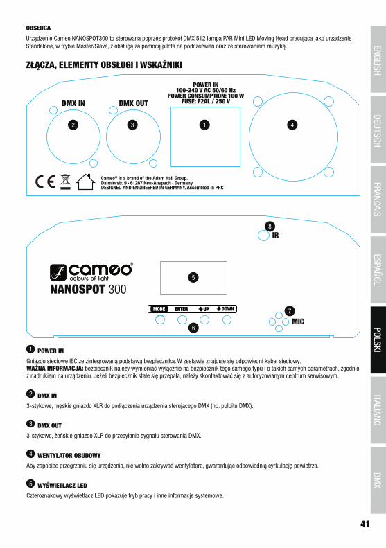
ITALIANOPOLSKI
ESPAÑOLFRANCAIS
DEUTSCHENGLISH
41
DMX
OBSŁUGA
Urządzenie Cameo NANOSPOT300 to sterowana poprzez protokół DMX 512 lampa PAR Mini LED Moving Head pracująca jako urządzenie Standalone, w trybie Master/Slave, z obsługą za pomocą pilota na podczerwień oraz ze sterowaniem muzyką.
ZŁĄCZA, ELEMENTY OBSŁUGI I WSKAŹNIKI
2 3 1 4
5
6
7
8
1 POWER IN
Gniazdo sieciowe IEC ze zintegrowaną podstawą bezpiecznika. W zestawie znajduje się odpowiedni kabel sieciowy. WAŻNA INFORMACJA: bezpiecznik należy wymieniać wyłącznie na bezpiecznik tego samego typu i o takich samych parametrach, zgodnie z nadrukiem na urządzeniu. Jeżeli bezpiecznik stale się przepala, należy skontaktować się z autoryzowanym centrum serwisowym.
2 DMX IN
3-stykowe, męskie gniazdo XLR do podłączenia urządzenia sterującego DMX (np. pulpitu DMX).
3 DMX OUT
3-stykowe, żeńskie gniazdo XLR do przesyłania sygnału sterowania DMX.
4 WENTYLATOR OBUDOWY
Aby zapobiec przegrzaniu się urządzenia, nie wolno zakrywać wentylatora, gwarantując odpowiednią cyrkulację powietrza.
5 WYŚWIETLACZ LED
Czteroznakowy wyświetlacz LED pokazuje tryb pracy i inne informacje systemowe.

42
DEUTSC
HFRAN
CAIS
ESPAÑO
LEN
GLISH
ITALIANO
POLSKI
DMX
6 PRZYCISKI OBSŁUGI
MODE: przejście w strukturze menu o jeden poziom wyżej, aż do widoku głównego.
ENTER: potwierdzenie wyboru programu i zmiany wartości.
UP i DOWN: wybór trybu pracy, ustawień systemu i programów, np. zmiana szybkości programu i adresu DMX.
7 MIC
Mikrofon do trybu pracy Sterowanie muzyką.
8 CZUJNIK PODCZERWIENI
Aby możliwa była wygodna obsługa lampy PAR za pomocą dołączonego pilota na podczerwień, należy pamiętać, aby interfejs podczerwieni pilota umieścić w bezpośrednim „kontakcie wzrokowym” z interfejsem podczerwieni lmpy PAR, w odległości maks. ok. 5 m.
WSKAZÓWKA w głowicy z projektorem znajduje się soczewka skupiająca projekcję na różnych odległościach. Rowkowana oprawka ułatwia obsługę (obrót w kierunku zgodnym z ruchem wskazówek zegara = obszar daleki, obrót w kierunku przeciwnym do ruchu wskazówek zegara = obszar bliski).
OBSŁUGAPo prawidłowym podłączeniu lampy PAR do sieci elektrycznej następuje restart silników (wyświetlacz = „InIt”). Po kilku sekundach lampa PAR jest gotowa do pracy i przełącza się na tryb, który ostatnio wybrano.
USTAWIANIE ADRESU STARTOWEGO I TRYBU PRACY DMXNaciskać przycisk MODE, dopóki na wyświetlaczu nie pojawi się jedna z pozycji menu „dMX”, „PrEF”, „SLAV”, „Soun” lub „Auto”. Za pomo-cą przycisków UP i DOWN wybrać pozycję menu „dMX” i nacisnąć przycisk ENTER. Na wyświetlaczu pojawi się napis „Add”. Po ponownym naciśnięciu przycisku ENTER zostanie wyświetlony adres DMX, który można ustawić za pomocą przycisków UP i DOWN (A001–A508). Po potwierdzeniu przyciskiem ENTER na wyświetlaczu pojawi się na krótko napis „SAVE”. Tryb pracy DMX należy ustawić poprzez wybór po-zycji menu „dMX”, naciśnięcie przycisku ENTER i wybór pozycji menu „ChAn” za pomocą przycisków UP i DOWN. Nacisnąć przycisk ENTER i za pomocą przycisków UP i DOWN wybrać żądany tryb pracy DMX (5Ch, 9Ch, 11Ch). Po potwierdzeniu przyciskiem ENTER na wyświetlaczu pojawi się na krótko napis „SAVE”. Sterowanie synchroniczne kilkoma lampami PAR tego samego modelu za pomocą jednego urządzenia sterującego DMX (np. pulpitu DMX) możliwe jest po ustawieniu w lampach PAR identycznego adresu startowego DMX i tego samego trybu pracy DMX oraz połączeniu ich kablami DMX.
UP/DOWN-> ENTER ->
<- MODEUP/DOWN –
-> ENTER ->
<- MODE
-> ENTER ->
<- MODEUP/DOWN / /
STEROWANIE AUTOMATYCZNE (AUTO)Wybrać jeden z 7 programów automatycznych (Sh01–Sh07) oraz ich szybkość (SP00–SP99). Naciskać przycisk MODE, dopóki na wyświe-tlaczu nie pojawi się jedna z pozycji menu „dMX”, „PrEF”, „SLAV”, „Soun” lub „Auto”. Za pomocą przycisków UP i DOWN wybrać pozycję menu „Auto” i nacisnąć przycisk ENTER (na wyświetlaczu pojawi się na krótko napis „SAVE”). Dwukrotnie nacisnąć przycisk ENTER, aby za pomocą przycisków UP i DOWN wybrać jeden z 7 programów automatycznych (ostatnie 2 cyfry wyświetlacza pulsują). Po potwierdzeniu przyciskiem ENTER na wyświetlaczu pojawi się na krótko napis „SAVE”. Na wyświetlaczu pojawi się aktywowany program i za pomocą przycisków UP i DOWN można wybrać pozycję menu służącą do ustawiania szybkości. Nacisnąć przycisk ENTER (ostatnie 2 znaki wyświe-tlacza pulsują) i za pomocą przycisków UP i DOWN wybrać szybkość w zakresie od SP00 do SP99. Po potwierdzeniu przyciskiem ENTER na wyświetlaczu pojawi się na krótko napis „SAVE”.
UP/DOWN-> ENTER ->
<- MODE
–
-> ENTER ->
<- MODE
UP/DOWNENTER
UP/DOWN
–

ITALIANOPOLSKI
ESPAÑOLFRANCAIS
DEUTSCHENGLISH
43
DMX
STEROWANIE MUZYKĄ (SOUND)Aby móc sterować lampą PAR poprzez zintegrowany mikrofon (impulsy basowe), należy wybrać tryb sterowania muzyką. Naciskać przycisk MODE, dopóki na wyświetlaczu nie pojawi się jedna z pozycji menu „dMX”, „PrEF”, „SLAV”, „Soun” lub „Auto”. Za pomocą przycisków UP i DOWN wybrać pozycję menu „Soun” i nacisnąć przycisk ENTER (na wyświetlaczu pojawi się na krótko napis „SAVE”). Ponowne nacisnąć przycisk ENTER, aby ustawić żądaną czułość, z jaką lampa PAR ma reagować na dźwięki (Su00–Su99). Po potwierdzeniu przyciskiem ENTER na wyświetlaczu pojawi się na krótko napis „SAVE”.
UP/DOWN-> ENTER ->
<- MODE
–
TRYB SLAVENaciskać przycisk MODE, dopóki na wyświetlaczu nie pojawi się jedna z pozycji menu „dMX”, „PrEF”, „SLAV”, „Soun” lub „Auto”. Za pomocą przycisków UP i DOWN wybrać pozycję menu „SLAV” i nacisnąć przycisk ENTER. Za pomocą przycisków UP i DOWN wybrać opcję „YES” i potwierdzić przyciskiem ENTER (na wyświetlaczu pojawi się na krótko napis „SAVE”). Połączyć jednostki Slave i Master (taki sam model) za pomocą kabla DMX i aktywować w jednostce Master jeden z trybów pracy Standalone. Jednostka Slave jest teraz podrzędna w stosunku do jednostki Master.
USTAWIENIA SYSTEMUAby dokonać ustawień systemu, należy naciskać przycisk MODE, dopóki na wyświetlaczu nie pojawi się jedna z pozycji menu „dMX”, „PrEF”, „SLAV”, „Soun” lub „Auto”. Za pomocą przycisków UP i DOWN wybrać pozycję menu „PrEF” i nacisnąć przycisk ENTER. Teraz za pomocą przycisków UP i DOWN można wybrać i edytować jedną z następujących pozycji menu (potwierdzenie za pomocą przycisku ENTER, opuszczenie ustawień za pomocą przycisku MODE):
UP/DOWN-> ENTER ->
<- MODEUP/DOWN /
-> ENTER ->
<- MODE
YES = wskazanie wyświetlaczazostanie obrócone o 180° (montaż nad głową)
-> ENTER ->
<- MODEUP/DOWN /
YES = odwrócenie kierunku ruchu PAN
-> ENTER ->
<- MODEUP/DOWN /
YES = odwrócenie kierunku ruchu TILT
-> ENTER ->
<- MODEUP/DOWN /
on = wyświetlacz włączony na stałeoff = wyświetlacz wyłączy się po ok. 20 sekundach bezczynności
Za pomocą tej pozycji menu można zdefiniowaćstan, w jaki urządzenie ma przejść,gdy nastąpi przerwa w sygnale DMXpodczas pracy w trybie DMX.
-> ENTER ->
<- MODEUP/DOWN
(Zaciem-
(Ostatnie polecenie
(Sterowanie

44
DEUTSC
HFRAN
CAIS
ESPAÑO
LEN
GLISH
ITALIANO
POLSKI
DMX
PILOT NA PODCZERWIEŃAby możliwa była wygodna obsługa lampy PAR za pomocą dołączonego pilota na podczerwień, należy pamiętać, aby interfejs podczerwieni pilota umieścić w bezpośrednim „kontakcie wzrokowym” z interfejsem podczerwieni lampy PAR, w odległości maks. ok. 5 m. Należy także przestrzegać kolejności etapów obsługi (1. „STAND BY”, 2. „FULL ON”).
STAND BY
Aby móc przełączyć lampę PAR na tryb obsługi za pomocą pilota na podczerwień, należy nacisnąć przycisk „STAND BY”. Na wyświetlaczu LED pojawi się napis „StoP”, a głowica ustawi się w pozycji wyprostowanej.
FULL ON
Po przełączeniu lampy PAR na tryb obsługi za pomocą pilota na podczerwień (patrz punkt „STAND BY”), nacisnąć przycisk „FULL ON”, aby włączyć oświetlenie LED.
GOBO
Po naciśnięciu przycisku „GOBO” można za pomocą przycisków numerycznych od 1 do 8 wybrać jedną z 7 tarcz Gobo lub opcję otwartą (1=otwarte).
COLOR
Po naciśnięciu przycisku „COLOR” można za pomocą przycisków numerycznych od 1 do 8 wybrać jeden z 7 filtrów kolorów lub opcję otwartą (1=otwarte).
STROBE
Aby aktywować efekt lampy stroboskopowej, należy nacisnąć przycisk „STROBE” i za pomocą przycisków numerycznych od 1 do 8 wybrać szybkość efektu stroboskopu (1 = stroboskop nieaktywny, 2 = najniższa częstotliwość błysków, 9 = najwyższa częstotliwość błysków).
DIMMER+
Aby zwiększyć jasność, należy nacisnąć przycisk „DIMMER+”.
DIMMER-
Aby zmniejszyć jasność, należy nacisnąć przycisk „DIMMER-”.
1–9
Przyciski numeryczne 1–9 służą do wyboru różnych tarcz Gobo, filtrów kolorów, szybkości efektu stroboskopu i programów wewnętrznych.
SOUND ON
Gdy wybrany jest jeden z 7 wewnętrznych programów z efektami, za pomocą przycisku „SOUND ON” można aktywować tryb sterowania muzyką. Wybrany program jest teraz sterowany poprzez wbudowany mikrofon i pulsuje w rytm muzyki (impulsy basowe).
SOUND OFF
Aby dezaktywować tryb sterowania muzyką, nacisnąć przycisk „SOUND OFF”.
SHOW
Po naciśnięciu przycisku „SHOW” można za pomocą przycisków numerycznych od 1 do 7 aktywować jeden z 7 różnych programów z efektami.
Aby opuścić tryb sterowania za pomocą pilota na podczerwień, nacisnąć ponownie przycisk „STAND BY”. Lampa PAR przełączy się na tryb pracy, który ostatnio wybrano.

ITALIANOPOLSKI
ESPAÑOLFRANCAIS
DEUTSCHENGLISH
45
DMX
USTAWIENIE I MONTAŻDzięki zintegrowanym gumowym nóżkom lampę PAR można ustawić w odpowiednim miejscu na scenie itp.
Do montażu na trawersie służy znajdujący się w zestawie pałąk Omega. Urządzenie należy zabezpieczyć dedykowaną liną zabezpieczającą, którą przymocowuje się do zabezpieczającej śruby oczkowej. Oba elementy przymocować do płyty nośnej lampy PAR, odpowiednie śruby
znajdują się w zestawie. Wskazówka: montaż nad głową może być wykonywany wyłącznie przez odpowiednio przeszkolony personel.
TECHNIKA DMX
DMX-512DMX (Digital Multiplex) to nazwa uniwersalnego protokołu transmisji do komunikacji między odpowiednimi urządzeniami a kontrolerami. Kontroler DMX wysyła dane DMX do podłączonych urządzeń DMX. Transmisja danych DMX następuje zawsze w formie szeregowego strumienia danych, który jest przekazywany z jednego urządzenia do następnego przez znajdujące się w każdym urządzeniu obsługującym standard DMX złącza „DMX IN” i „DMX OUT” (złącza wtykowe XLR), przy czym maksymalna liczba urządzeń nie może przekraczać 32. Ostatnie urządzenie w łańcuchu należy wyposażyć w terminator.
ZŁĄCZE DMX:DMX to wspólny „język”, za pomocą którego różne typy i modele urządzeń różnych producentów porozumiewają się ze sobą i mogą być sterowane przy użyciu centralnego kontrolera, o ile wszystkie urządzenia i kontroler obsługują standard DMX. W celu zapewnienia optymalnej transmisji danych wymagane jest, aby kable połączeniowe między poszczególnymi urządzeniami były możliwie jak najkrótsze. Kolejność, w jakiej urządzenia są podłączone do sieci DMX, nie ma znaczenia dla adresowania. I tak urządzenie z adresem DMX 1 może znajdować się w dowolnym miejscu (szeregowego) łańcucha DMX – na początku, na końcu lub gdzieś pośrodku. Po przydzieleniu urządzeniu adresu DMX 1, kontroler „wie”, że ma on wysyłać wszystkie dane przypisane do adresu 1 do tego urządzenia, niezależnie od jego pozycji w sieci DMX. POŁĄCZENIE SZEREGOWE KILKU REFLEKTORÓW1. Męską wtyczkę XLR (3-stykową lub 5-stykową) kabla DMX podłączyć do wyjścia DMX (żeńskie gniazdo XLR) pierwszego urządzenia DMX (np. kontrolera DMX).2. Żeńską wtyczkę XLR kabla DMX podłączonego do pierwszego reflektora podłączyć do wejścia DMX (męskie gniazdo XLR) następnego urządzenia DMX. Wyjście DMX tego urządzenia podłączyć w taki sam sposób do wejścia DMX następnego urządzenia i tak dalej. Należy pamiętać, że urządzenia DMX podłącza się szeregowo, a połączeń nie można rozdzielać bez aktywnego rozdzielacza. Maksymalna liczba urządzeń DMX w łańcuchu DMX nie może przekraczać 32.
Obszerny wybór odpowiednich kabli DMX oferują linie produktów Adam Hall 3 STAR, 4 STAR i 5 STAR.
KABEL DMX:W przypadku stosowania własnych kabli należy bezwzględnie przestrzegać informacji podanych na ilustracjach na tej stronie. W żadnym wypadku nie wolno łączyć osłony kabla z końcówką uziemiającą wtyczki. Należy także pamiętać, aby osłona nie miała kontaktu z obudową wtyczki XLR. Jeśli osłona ma kontakt z uziemieniem, może dojść do awarii systemu.
Przyporządkowanie wtyczek:Kabel DMX z 3-stykowymi wtyczkami XLR: Kabel DMX z 5-stykowymi wtyczkami XLR (pin 4 i 5 są niepodłączone):
Shield
23
1
23
1
123
45
12
34
5
Shield
TERMINATOR DMX:Aby zapobiec awariom systemu, należy wyposażyć ostatnie urządzenie w łańcuchu DMX w terminator (120 Ω, 1/4 W).3-stykowa wtyczka XLR z terminatorem: K3DMXT35-stykowa wtyczka XLR z terminatorem: K3DMXT5
Przyporządkowanie wtyczek:3-stykowa wtyczka XLR: 5-stykowa wtyczka XLR:
23
1
12
34
5
ADAPTER DMX:Możliwa jest także kombinacja urządzeń DMX z 3-stykowymi przyłączami i urządzeń DXM z 5-stykowymi przyłączami w jednym łańcuchu DMX przy użyciu adapterów.

46
DEUTSC
HFRAN
CAIS
ESPAÑO
LEN
GLISH
ITALIANO
POLSKI
DMX
Przyporządkowanie wtyczekAdapter DMX 5-stykowy XLR, męski, na 3-stykowy XLR, żeński: K3DGF0020Pin 4 i 5 są niepodłączone.
Przyporządkowanie wtyczekAdapter DMX 3-stykowy XLR, męski, na 5-stykowy XLR, żeński: K3DHM0020Pin 4 i 5 są niepodłączone.
DANE TECHNICZNEOznaczenie modelu: CLNS300
Rodzaj produktu: LED Moving Head
Typ: Spot
Spektrum kolorów: W
Liczba diod LED: 1
Typ diod LED: 30 W
Kąt emisji: 13°
Wejście DMX: męskie, 3-stykowe, XLR
Wyjście DMX: żeńskie, 3-stykowe, XLR
Tryb DMX: 5-kanałowy, 9-kanałowy i 11-kanałowy
Funkcje DMX: Pan/Tilt, dokładna regulacja Pan/Tilt, tarcza kolorów, tarcza Gobo, szybkość silnika, programy automatyczne, sterowanie muzyką, stroboskop, ściemnianie
Funkcje Standalone: programy automatyczne, sterowanie muzyką, tryby pracy Master/Slave
Sterowanie: DMX512, pilot na podczerwień
Elementy obsługi: Mode, Enter, Up, Down
Wskaźniki: 4-znakowy wyświetlacz LED
Kąt ruchu PAN: 540°
Kąt ruchu TILT: 230°
Napięcie robocze: 100–240 V AC/50–60 Hz
Pobór mocy: 100 W
Strumień świetlny: 650 lm
Natężenie oświetlenia (w odległości 1 m): 24 500 lx
Złącze zasilania: gniazdo sieciowe IEC
Bezpiecznik: F2 AL/250 V (5 x 20 mm)
Temperatura otoczenia (w trakcie pracy): 0°C–40°C
Względna wilgotność powietrza: < 85%, bez kondensacji
Materiał obudowy: metal, ABS
Kolor obudowy: czarny
Chłodzenie obudowy: wentylator
Wymiary (szer. x wys. x gł., bez pałąka montażo-wego):
165 x 280 x 155 mm
Waga: 3 kg
Pozostałe cechy: kabel sieciowy, pilot na podczerwień, zabezpieczająca śruba oczkowa i pałąk mon-tażowy Omega w zestawie

ITALIANOPOLSKI
ESPAÑOLFRANCAIS
DEUTSCHENGLISH
47
DMX
DEKLARACJE PRODUCENTA
GWARANCJA PRODUCENTA I OGRANICZENIE ODPOWIEDZIALNOŚCI Nasze aktualne warunki gwarancji i informacje dotyczące ograniczenia odpowiedzialności znajdą Państwo na stronie: http://www.adamhall.com/media/shop/downloads/documents/manufacturersdeclarations.pdf. W razie konieczności skorzystania z serwisu proszę skontaktować się z firmą Adam Hall GmbH, Daimlerstraße 9, 61267 Neu Anspach / e-mail [email protected] / +49 (0)6081 / 9419-0.
PRAWIDŁOWA UTYLIZACJA NINIEJSZEGO PRODUKTU (Obowiązuje w Unii Europejskiej i innych krajach europejskich stosujących system sortowania odpadów) Niniejszy symbol na produk-cie lub związanych z nim dokumentach wskazuje, iż urządzenie po zakończeniu okresu użytkowania nie może być utylizowane razem
ze standardowymi odpadami domowymi, aby uniknąć szkód w środowisku lub szkód na osobie powstałych w wyniku niekontrolowanego usuwania odpadów. Niniejszy produkt należy utylizować oddzielnie od innych odpadów i przekazać do punktu recyklingu w celu ponownego wykorzystania użytych w nim materiałów w ramach idei zrównoważonego rozwoju. Klienci prywatni otrzymują informacje w zakresie przyja-znych dla środowiska możliwości usuwania odpadów od sprzedawcy, u którego produkt został zakupiony, lub w odpowiednich placówkach regionalnych. Użytkownicy będący przedsiębiorcami proszeni są o kontakt ze swoimi dostawcami i ewentualne sprawdzenie uzgodnionych umownie warunków utylizacji urządzeń. Niniejszy produkt nie może być utylizowany razem z innymi odpadami przemysłowymi.
Deklaracja zgodności CEFirma Adam Hall GmbH niniejszym oświadcza, że produkt ten jest zgodny z następującymi dyrektywami (o ile mają zastosowanie):dyrektywa w sprawie urządzeń radiowych i końcowych urządzeń telekomunikacyjnych (1999/5/WE) lub dyrektywa w sprawie urządzeń radiowych (2014/53/UE) od czerwca 2017 r.dyrektywa niskonapięciowa (2014/35/UE)dyrektywa w sprawie kompatybilności elektromagnetycznej (2014/30/UE)dyrektywa w sprawie ograniczenia stosowania niektórych niebezpiecznych substancji w sprzęcie elektrycznym i elektronicznym (2011/65/UE)Pełna wersja deklaracji zgodności znajduje się na stronie internetowej www.adamhall.com. Ponadto zapytania w tej sprawie można przesyłać na adres e-mail [email protected].

48
DEUTSC
HFRAN
CAIS
ESPAÑO
LEN
GLISH
ITALIANO
POLSKI
DMX
ITALIANO
Avete fatto la scelta giusta!Questo dispositivo è stato sviluppato e prodotto in conformità con elevati standard qualitativi che ne garantiscono il regolare funzionamento per molti anni. Leggete attentamente questo manuale d‘uso per utilizzare al meglio il vostro nuovo prodotto Cameo Light. Per maggiori informazioni su Cameo Light consultare la nostra pagina Web WWW.CAMEOLIGHT.COM.
MISURE PRECAUZIONALI1. Lesen S1. Leggere attentamente il presente manuale di istruzioni. 2. Conservare tutte le indicazioni e le istruzioni in un luogo sicuro. 3. Seguire le istruzioni. 4. Rispettare tutte le avvertenze. Non rimuovere dal dispositivo le indicazioni sulla sicurezza o altre informazioni. 5. Utilizzare il dispositivo solo nei modi previsti dal manuale. 6. Utilizzare esclusivamente stativi e fissaggi stabili e adatti (per installazioni fisse). Verificare che i supporti a parete siano installati e fissati a regola d‘arte. Verificare che il dispositivo sia installato in modo stabile e non possa cadere. 7. Durante l‘installazione, osservare le normative sulla sicurezza in vigore nel proprio Paese. 8. Non installare né azionare il dispositivo in prossimità di radiatori, accumulatori termici, stufe o altre fonti di calore. Accertarsi che il dispositivo sia sempre installato in modo che venga raffreddato a sufficienza e non possa surriscaldarsi. 9. Non appoggiare sul dispositivo fonti di combustione, quali candele accese. 10. Le fessure di areazione non devono essere bloccate. 11. Il dispositivo è destinato all‘impiego esclusivamente in ambienti chiusi; non deve essere utilizzato nelle immediate vicinanze di acqua (questo punto non interessa i dispositivi specifici per l‘esterno, per i quali valgono le indicazioni speciali riportate di seguito). Non portare mai il dispositivo a contatto con materiali, liquidi o gas infiammabili. 12. Accertarsi che all‘interno del dispositivo non possa penetrare acqua per gocciolamento o spruzzo. Non collocare sul dispositivo oggetti contenenti liquidi, quali vasi, tazze o bicchieri. 13. Assicurarsi che non sia possibile la caduta di oggetti nel dispositivo. 14. Azionare il dispositivo esclusivamente con gli accessori appositamente consigliati e previsti dal produttore. 15. Non aprire né modificare il dispositivo. 16. Una volta collegato il dispositivo, verificare tutti i cavi per evitare danni o incidenti, ad esempio per inciampo. 17. Durante il trasporto, assicurarsi che il dispositivo non possa cadere e causare possibili danni a cose e/o persone.18. Se il dispositivo non funzionasse più correttamente, vi fosse caduto sopra del liquido o un oggetto o fosse stato danneggiato in altro modo, spegnerlo immediatamente e staccare la spina (se si tratta di un dispositivo attivo). La riparazione del dispositivo deve essere affidata esclusivamente a personale qualificato autorizzato. 19. Per la pulizia del dispositivo utilizzare un panno pulito. 20. Rispettare le leggi sullo smaltimento in vigore nel Paese di installazione. Al momento di smaltire l‘imballo, separare la plastica dalla carta e dal cartone. 21. I sacchetti di plastica devono essere tenuti lontani dalla portata dei bambini.
DISPOSITIVI CON ALLACCIAMENTO DI RETE:22. ATTENZIONE: se il cavo di rete è dotato di contatto di protezione, deve essere collegato a una presa di rete con messa a terra. Non disattivare mai la connessione di messa a terra di un cavo di rete. 23. Non accendere il dispositivo subito dopo essere stato sottoposto a forti variazioni di temperatura (ad esempio dopo il trasporto). Umidità e condensa potrebbero danneggiare il dispositivo. Accendere il dispositivo solo dopo che ha raggiunto la temperatura ambiente. 24. Prima di collegare il dispositivo alla presa, controllare innanzitutto se la tensione e la frequenza della rete elettrica coincidono con i valori indicati sul dispositivo stesso. Nel caso di dispositivo munito di selettore di tensione, collegarlo alla presa unicamente se i valori del dispositivo coincidono con quelli della rete elettrica. Se il cavo di rete o l‘adattatore di rete forniti in dotazione non sono compatibili con la presa, rivolgersi a un elettricista. 25. Non calpestare il cavo di rete. Accertarsi che i cavi sotto tensione, in particolare della presa di rete o dell‘adattatore di rete, non vengano pizzicati. 26. Durante il cablaggio del dispositivo, verificare sempre che il cavo di rete e l‘adattatore di rete siano costantemente accessibili. Staccare sempre il dispositivo dall‘alimentazione di rete quando non è utilizzato o durante la pulizia. Per staccare dalla presa il cavo di rete e l‘adatta-tore di rete, tirare sempre dalla spina o dall‘adattatore e non dal cavo. Non toccare mai il cavo di alimentazione e l’alimentatore con le mani umide. 27. Evitare per quanto possibile di accendere e spegnere velocemente il dispositivo per non pregiudicarne la durata.28. NOTA IMPORTANTE: Sostituire i fusibili esclusivamente con fusibili dello stesso tipo e valore. Se un fusibile continua a saltare, rivolgersi a un centro di assistenza autorizzato. 29. Per staccare completamente il dispositivo dalla rete elettrica, rimuovere il cavo di rete o l‘adattatore di rete dalla presa. 30. Per staccare un dispositivo provvisto di presa Volex, è prima necessario sbloccare la relativa spina Volex del dispositivo stesso. Tirando il cavo di rete, però, il dispositivo potrebbe spostarsi e cadere, provocando danni alle persone o di altro genere. Prestare quindi la più scrupo-losa attenzione durante la posa dei cavi. 31. In caso di pericolo di caduta di fulmine, o se il dispositivo rimane inutilizzato a lungo, staccare sempre il cavo di rete e l‘adattatore di rete dalla presa.32. L‘installazione del dispositivo deve essere realizzata unicamente in assenza di tensione (staccare la spina dalla rete elettrica).33. Polvere e depositi di altra natura all‘interno del dispositivo possono danneggiarlo. A seconda delle condizioni ambientali (polvere, nicotina, nebbia ecc.) il dispositivo deve essere sottoposto a regolari interventi di manutenzione e pulizia da parte di personale specializzato

ITALIANOPOLSKI
ESPAÑOLFRANCAIS
DEUTSCHENGLISH
49
DMX
(senza garanzia, interventi a carico del proprietario) per evitare surriscaldamento e malfunzionamenti.34. La distanza dai materiali infiammabili deve essere di almeno 0,5 m35. I cavi di rete utilizzati per l’alimentazione elettrica di più dispositivi devono avere una sezione di almeno 1,5 mm². I cavi impiegati nell’Unione Europea devono essere di tipo H05VV-F o simile. Adam Hall offre cavi idonei. Tali cavi consentono di collegare più dispositivi dalla presa di uscita POWER OUT di un apparecchio alla presa POWER IN di un altro dispositivo. La potenza assorbita complessivamente da tutti i dispositivi non deve superare il valore indicato (v. stampigliatura sul dispositivo stesso). Aver cura di mantenere i cavi di rete quanto più possibile corti.
ATTENZIONE:non togliere mai il coperchio di protezione perché sussiste il pericolo di scosse elettriche. L‘inter-no del dispositivo non contiene parti che possono essere riparate o sottoposte a manutenzione da parte dell‘utente. Per gli interventi di manutenzione e di riparazione rivolgersi esclusivamente a personale qualificato.
Il triangolo equilatero con il simbolo del lampo segnala la presenza di tensioni pericolose non isolate all‘interno dell‘apparec-chio che possono causare scosse elettriche.
Il triangolo equilatero con punto esclamativo segnala la presenza di importanti informazioni relative all’uso e alla manutenzione.
Avvertimento! Questo simbolo indica superfici calde. Alcune parti della cassa potrebbero scaldarsi durante l‘impiego. Dopo aver usato l‘apparecchiatura, lasciarla raffreddare per almeno 10 minuti prima di toccarla o trasportarla.
Avvertimento! Questo dispositivo è destinato per l’utilizzo a un’altitudine non superiore ai 2.000 metri sul livello del mare.
Avvertimento! Questo dispositivo non è destinato all’uso nei climi tropicali.
ATTENZIONE! INDICAZIONI IMPORTANTI RELATIVE AI PRODOTTI DI ILLUMINAZIONE!1. Il prodotto è stato sviluppato per un uso professionale nel settore della tecnologia applicata a spettacoli e non è idoneo all‘impiego nell‘illuminazione domestica.2. Non fissare mai direttamente il fascio di luce, nemmeno per brevi istanti. 3. Non guardare mai il fascio di luce con dispositivi ottici quali le lenti d‘ingrandimento.4. In alcuni casi, in persone sensibili gli effetti stroboscopici possono causare attacchi epilettici! Le persone affette da epilessia devono perciò assolutamente evitare luoghi in cui vengono impiegati effetti stroboscopici.
INTRODUZIONEMINI TESTA MOBILE 30 W
CLNS300
FUNZIONI DI COMANDO
Controllo DMX a 5 canali, 9 canali, 11 canali
Telecomando a infrarossi
Funzionamento master/slave
Modalità standalone
CARATTERISTICHE
Mini testa mobile con LED bianco freddo da 30 W, ruota di colori con 7 colori e 1 libero, ruota gobo con 7 gobo e 1 libero, giro orizzontale a 540° PAN e verticale a 230° TILT, 3 modalità DMX, comando DMX512, funzionamento master/slave, programmi standalone, comando tra-mite musica mediante microfono integrato, opzioni di montaggio universali, piedini in gomma, occhiello a vite di sicurezza e 1 staffa Omega inclusi, tensione di esercizio da 100-240 V AC, 50/60 Hz, potenza assorbita 100 W.
UTILIZZO
Il Cameo NANOSPOT300 è una mini testa mobile a LED con controllo DMX512 impiegabile come apparecchio standalone, con funzionamen-to master/slave, telecomando a infrarossi e con comando tramite musica.

50
DEUTSC
HFRAN
CAIS
ESPAÑO
LEN
GLISH
ITALIANO
POLSKI
DMX
CONNESSIONI, ELEMENTI DI COMANDO E VISUALIZZAZIONE
2 3 1 4
5
6
7
8
1 POWER IN
Presa di rete IEC con portafusibili integrato. In dotazione viene fornito un cavo di alimentazione idoneo. NOTA IMPORTANTE: sostituire il fusibile unicamente con un fusibile dello stesso tipo e avente gli stessi valori serigrafati sul dispositivo. Se il fusibile continua a saltare, rivolgersi a un centro di assistenza autorizzato.
2 DMX IN
Presa XLR maschio a 3 poli per il collegamento di un apparecchio di controllo DMX (ad esempio mixer DMX).
3 DMX OUT
Presa XLR femmina a 3 poli per l’inoltro del segnale di controllo DMX.
4 VENTOLA
Per evitare che il dispositivo si surriscaldi, assicurarsi che la ventola non sia coperta in alcun modo e che l’aria circoli liberamente.
5 DISPLAY LED
Il display LED a quattro digiti mostra la modalità di funzionamento e altre informazioni di sistema.
6 TASTI DI COMANDO
MODE: consente di accedere a un livello superiore della struttura menu, fino alla videata principale.
ENTER: consente di confermare la selezione del programma e delle modifiche dei valori.
UP e DOWN: selezione di una modalità di funzionamento, di impostazioni di sistema e di programmi, ad esempio modifica della velocità programma e dell’indirizzo DMX.

ITALIANOPOLSKI
ESPAÑOLFRANCAIS
DEUTSCHENGLISH
51
DMX
7 MIC
Microfono per la modalità di funzionamento Comando tramite musica.
8 SENSORE INFRAROSSI
Per controllare comodamente la testa mobile utilizzando il telecomando a infrarossi in dotazione, ricordare che l’interfaccia a infrarossi del telecomando deve essere orientata direttamente verso l’interfaccia a infrarossi del proiettore laser a una distanza di circa 5 m.
NOTA la testa del proiettore della testa mobile contiene la lente con cui mettere a fuoco la proiezione a distanze diverse. La forma arro-tondata permette una maggiore maneggevolezza (rotazione in senso orario = lunga distanza, rotazione in senso antiorario = breve distanza).
UTILIZZONon appena il faro è collegato correttamente alla rete elettrica, i motori vengono resettati. (Display = “InIt”). Dopo alcuni secondi, il faro è pronto per l’uso e passa alla modalità di funzionamento precedentemente selezionata.
IMPOSTAZIONE DELL’INDIRIZZO DI AVVIO DMX E DELLA MODALITÀ DMXPremere più volte il tasto MODE finché sul display non appare una delle voci menu “dMX”, “PrEF”, “SLAV”, “Soun” o “Auto”. Con i tasti UP e DOWN selezionare quindi la voce di menu “dMX” e premere ENTER. Ora sul display appare “Add”; premendo di nuovo ENTER viene visualizzato l’indirizzo di avvio DMX, che può essere impostato a piacere con i tasti UP e DOWN (A001 - A508). Dopo la conferma con ENTER, sul display appare brevemente il testo “SAVE”. Per impostare la modalità DMX, selezionare la voce di menu “dMX”, premere ENTER e con i tasti UP e DOWN selezionare la voce di menu “ChAn”. Premere ENTER e con i tasti UP e DOWN selezionare la modalità DMX desiderata (5Ch, 9Ch, 11Ch). Dopo la conferma con ENTER, sul display appare brevemente il testo “SAVE”. Il controllo simultaneo di più fari dello stesso modello (ad esempio mixer DMX) si ottiene impostando i fari su un indirizzo di avvio DMX identico e sulla stessa modalità DMX, collegandoli con i cavi DMX.
UP/DOWN-> ENTER ->
<- MODEUP/DOWN –
-> ENTER ->
<- MODE
-> ENTER ->
<- MODEUP/DOWN / /
COMANDO AUTOMATICO (AUTO)Selezionare uno dei 7 programmi auto (Sh01 - Sh07) e la relativa velocità di avanzamento (SP00 - SP99). Premere più volte il tasto MODE finché sul display non appare una delle voci menu “dMX”, “PrEF”, “SLAV”, “Soun” o “Auto”. Con i tasti UP e DOWN selezionare quindi la voce di menu “Auto” e premere ENTER (sul display appare brevemente il testo “SAVE”). Premere due volte ENTER per selezionare uno dei 7 programmi auto con i tasti UP e DOWN (le ultime 2 cifre del display lampeggiano). Dopo la conferma con ENTER, sul display appare brevemente il testo “SAVE”. Ora sul display viene visualizzato il programma attivato e con i tasti UP e DOWN è possibile selezionare la voce di menu relativa alla velocità di avanzamento. Premere ENTER (le ultime 2 cifre del display lampeggiano) e con i tasti UP e DOWN impostare la velocità su un valore compreso tra SP00 e SP99. Dopo la conferma con ENTER, sul display appare brevemente il testo “SAVE”.
UP/DOWN-> ENTER ->
<- MODE
–
-> ENTER ->
<- MODE
UP/DOWNENTER
UP/DOWN
–
COMANDO TRAMITE MUSICA (SOUND)Selezionare la modalità di funzionamento Comando tramite musica per comandare la testa mobile tramite il microfono integrato (impulsi gravi). Premere più volte il tasto MODE finché sul display non appare una delle voci menu “dMX”, “PrEF”, “SLAV”, “Soun” o “Auto”. Con i tasti UP e DOWN selezionare quindi la voce di menu “Soun” e premere ENTER (sul display appare brevemente il testo “SAVE”). Premere brevemente ENTER per impostare sul valore desiderato (Su00 - Su99) la sensibilità con cui il faro deve reagire ai rumori. Dopo la conferma con ENTER, sul display appare brevemente il testo “SAVE”.
UP/DOWN-> ENTER ->
<- MODE
–

52
DEUTSC
HFRAN
CAIS
ESPAÑO
LEN
GLISH
ITALIANO
POLSKI
DMX
MODALITÀ SLAVEPremere più volte il tasto MODE finché sul display non appare una delle voci menu “dMX”, “PrEF”, “SLAV”, “Soun” o “Auto”. Con i tasti UP e DOWN selezionare quindi la voce di menu “SLAV” e premere ENTER. Con i tasti UP e DOWN selezionare quindi “YES” e confermare con ENTER (sul display appare brevemente il testo “SAVE”). Collegare le unità slave e master (stesso modello) con l’ausilio di un cavo DMX e sull’unità master attivare una delle modalità standalone. Ora l’unità slave segue l’unità master.
IMPOSTAZIONI DI SISTEMAPer eseguire le impostazioni di sistema, premere più volte il tasto MODE finché sul display non appare una delle voci menu “dMX”, “PrEF”, “SLAV”, “Soun” o “Auto”. Con i tasti UP e DOWN selezionare quindi la voce di menu “PrEf” e premere ENTER. Con i tasti UP e DOWN selezio-nare e impostare una delle seguenti voci di menu (confermare con ENTER, uscire con MODE):
UP/DOWN-> ENTER ->
<- MODEUP/DOWN /
-> ENTER ->
<- MODE
YES = la schermata del displayruota di 180° (montaggio sopratesta)
-> ENTER ->
<- MODEUP/DOWN /
YES = inversione giro orizzontale (PAN)
-> ENTER ->
<- MODEUP/DOWN /
YES = inversione giro verticale (TILT)
-> ENTER ->
<- MODEUP/DOWN /
on = display sempre accesooff = il display si spegne dopo circa 20 secondi di inattività
Questa voce di menu consente di definirequale modalità operativa deve attivarsiin caso di interruzione del segnale DMXnella modalità DMX.
-> ENTER ->
<- MODEUP/DOWN
(oscuramento)
(ultimo comando DMX)
(comando tramite musica)
TELECOMANDO A INFRAROSSIPer comandare comodamente la testa mobile con il telecomando a infrarossi in dotazione, ricordare che l’interfaccia a infrarossi del telecomando deve essere orientata direttamente verso l’interfaccia a infrarossi del proiettore laser a una distanza di circa 5 m; continuare con la sequenza dei passi operativi (1. “STAND BY”, 2. “FULL ON”).
STAND BY
Premere “STAND BY” per abilitare la modalità di funzionamento Telecomando a infrarossi della testa mobile. Sul display a LED ora appare “StoP” e la testa si colloca in posizione verticale.
FULL ON
Dopo aver attivato la modalità di funzionamento Telecomando a infrarossi della testa mobile (v. punto “STAND BY”), premere “FULL ON” per attivare il LED di illuminazione.
GOBO
Dopo aver premuto “GOBO”, è possibile selezionare uno dei 7 gobo e 1 libero con i tasti numerici da 1 a 8 (1 = libero).

ITALIANOPOLSKI
ESPAÑOLFRANCAIS
DEUTSCHENGLISH
53
DMX
COLOR
Dopo aver premuto “COLOR”, è possibile selezionare uno dei 7 filtri colore e 1 libero con i tasti numerici da 1 a 8 (1 = libero).
STROBE
Per attivare l’effetto stroboscopio, premere “STROBE”, quindi selezionare la velocità stroboscopica con i tasti numerici da 1 a 9 (1 = strobo-scopio disattivato, 2 = frequenza di lampeggio più lenta, 9 = frequenza di lampeggio più rapida).
DIMMER+
Premere “DIMMER+” per aumentare la luminosità.
DIMMER-
Premere “DIMMER−” per ridurre la luminosità.
1 - 9
I tasti numerici da 1 a 9 consentono di selezionare i diversi gobo, i filtri colore, la velocità stroboscopica e i programmi interni.
SOUND ON
Con uno dei 7 programmi Show interni selezionato, premendo “SOUND ON” è possibile attivare la modalità di funzionamento Comando tramite musica. Il programma selezionato sarà ora comandato tramite il microfono integrato e seguirà il ritmo della musica (impulsi gravi).
SOUND OFF
Per disattivare la modalità di funzionamento Comando tramite musica, premere “SOUND OFF”.
SHOW
Premere “SHOW” per selezionare uno dei 7 programmi Show con i tasti numerici da 1 a 7.
Per uscire dalla modalità di funzionamento con telecomando IR, premere brevemente “STAND BY”. Il faro torna così alla modalità di funzio-namento attiva in precedenza.
INSTALLAZIONE E MONTAGGIOGrazie ai piedini in gomma integrati, il faro può essere collocato in un punto adatto, ad esempio sul pavimento del palco.
Il montaggio su una traversa si esegue mediante la staffa Omega in dotazione; fissare il dispositivo all'occhiello a vite di sicurezza con un
cavo idoneo. Fissare entrambi gli elementi alla base del faro. Le viti idonee sono fornite in dotazione. Nota: Il montaggio sopratesta deve essere eseguito esclusivamente da personale qualificato.

54
DEUTSC
HFRAN
CAIS
ESPAÑO
LEN
GLISH
ITALIANO
POLSKI
DMX
TECNOLOGIA DMX
DMX512DMX (Digital Multiplex) è la sigla di un protocollo di trasmissione universale per la comunicazione tra dispositivi e controller. Un controller DMX invia dati DMX ai dispositivi DMX collegati. I dati DMX vengono sempre trasmessi come flusso di dati seriale, che viene inoltrato da un dispositivo collegato al successivo attraverso le connessioni (connettori XLR) DMX IN e DMX OUT presenti per ogni dispositivo DMX compatibile, per un massimo di 32 dispositivi. L'ultimo dispositivo della catena deve essere dotato di un connettore terminale (terminatore).
COLLEGAMENTO DMX:DMX è il linguaggio condiviso che consente l'accoppiamento tra diversi tipi di dispositivo e modelli di produttori differenti e il controllo da parte di un controller centrale, a condizione che tutti i dispositivi e il controller siano DMX compatibili. Per una trasmissione dei dati ottimale, il cavo che collega i singoli dispositivi deve essere il più corto possibile. L'ordine dei dispositivi nella rete DMX non influisce sull'indirizzamento. Il dispositivo con indirizzo DMX 1 può quindi trovarsi in una posizione qualsiasi della catena DMX (seriale): all'inizio, alla fine o in qualsiasi punto al centro. Se a un dispositivo viene assegnato l'indirizzo DMX 1, il controller "sa" di dover inviare a questo dispositivo tutti i dati attribuiti all'indirizzo 1, indipendentemente dalla sua posizione nella interconnessione DMX.
ACCOPPIAMENTO SERIALE DI PIÙ PROIETTORI1. Collegare il connettore XLR maschio (a 3 o 5 poli) del cavo DMX con l'uscita DMX (presa XLR femmina) del primo dispositivo DMX (ad esempio controller DMX).2. Collegare il connettore XLR femmina del cavo DMX connesso al primo proiettore DMX con l'ingresso DMX (presa XLR maschio) del successivo dispositivo DMX. Analogamente, collegare l'uscita DMX di questo dispositivo con l'ingresso DMX del dispositivo seguente e così via. Tenere presente che in linea di principio i dispositivi DMX sono collegati in serie e i collegamenti non si possono condividere senza uno splitter attivo. In una catena DMX i dispositivi DMX non possono essere più di 32.
Nelle linee di prodotti Adam Hall 3 STAR, 4 STAR e 5 STAR è disponibile un'ampia scelta di cavi DMX.
CAVO DMX:In caso di cavi di propria realizzazione, procedere secondo le figure di questa pagina. Non collegare mai la schermatura dei cavi con il contatto di massa del connettore e assicurarsi che la schermatura non entri in contatto con l'involucro del connettore XLR. Il contatto di massa della schermatura può generare guasti al sistema.
Configurazione dei connettori:Cavo DMX con connettori XLR a 3 poli: Cavo DMX con connettori XLR a 5 poli (pin 4 e 5 non assegnati):
Shield
23
1
23
1
123
45
12
34
5
Shield
CONNETTORE TERMINALE DMX (TERMINATORE):Per evitare errori di sistema, l'ultimo dispositivo di una catena DMX deve essere dotato di una resistenza di terminazione (120 ohm, 1/4 W).Connettore XLR a 3 poli con resistenza di terminazione: K3DMXT3Connettore XLR a 5 poli con resistenza di terminazione: K3DMXT5
Configurazione dei connettori:Connettore XLR a 3 poli: Connettore XLR a 5 poli:
23
1
12
34
5
ADATTATORE DMX:Se si utilizzano degli adattatori, in una catena DMX si possono anche combinare dispositivi DMX con collegamenti a 3 poli e dispositivi DMX con collegamenti a 5 poli.
Configurazione dei connettoriAdattatore DMX XLR maschio 5 poli a XLR femmina 3 poli: K3DGF0020Pin 4 e 5 non assegnati.
Configurazione dei connettoriAdattatore DMX XLR maschio 3 poli a XLR femmina 5 poli: K3DHM0020Pin 4 e 5 non assegnati.

ITALIANOPOLSKI
ESPAÑOLFRANCAIS
DEUTSCHENGLISH
55
DMX
DATI TECNICINome del modello: CLNS300
Tipo di prodotto: Testa mobile LED
Tipo: Spot
Spettro cromatico: Bianco
Numero di LED: 1
Tipo di LED: 30 W
Angolo di proiezione: 13°
Ingresso DMX: XLR maschio a 3 poli
Uscita DMX: XLR femmina a 3 poli
Modalità DMX: 5 canali, 9 canali, 11 canali
Funzioni DMX: Pan/Tilt, Pan/Tilt fine, ruota colori, ruota gobo, velocità motore, programmi auto, comando tramite musica, stroboscopio, dimmer
Funzioni standalone: Programmi auto, comando tramite musica, funzionamento master/slave
Comando: DMX512, telecomando IR
Elementi di comando: Mode, Enter, Up, Down
Indicatori: Display LED a 4 digiti
Angolo del giro orizzontale (pan): 540°
Angolo del giro verticale (tilt): 230°
Tensione di esercizio: 100 - 240 V AC, 50/60 Hz
Potenza assorbita: 100 W
Flusso luminoso: 650 lm
Potenza di illuminazione (a 1 m): 24.500 lx
Collegamento alimentazione elettrica: Presa IEC
Fusibile: F2AL / 250V (5 x 20 mm)
Temperatura ambiente (in esercizio): 0 °C - 40 ℃
Umidità relativa dell'aria: < 85%, senza condensazione
Materiale cassa: Metallo, ABS
Colore cassa: Nero
Raffreddamento della cassa: Ventola
Ingombro (L x H x P, senza staffa di montaggio): 165 x 280 x 155 mm
Peso: 3 kg
Altre caratteristiche: Cavo di alimentazione, telecomando a infrarossi, occhiello a vite di sicurezza e staffa di montaggio Omega in dotazione

56
DEUTSC
HFRAN
CAIS
ESPAÑO
LEN
GLISH
ITALIANO
POLSKI
DMX
DICHIARAZIONI DEL PRODUTTORE
MANUFACTURER’S WARRANTY & LIMITATION OF LIABILITY Le nostre attuali condizioni di garanzia e la limitazione di responsabilità sono consultabili alla pagina: http://www.adamhall.com/media/shop/downloads/documents/manufacturersdeclarations.pdf. In caso di assistenza, rivolgersi a Adam Hall GmbH, Daimlerstraße 9, 61267 Neu Anspach / E-mail [email protected] / +49 (0)6081 / 9419-0.
CORRETTO SMALTIMENTO DEL PRODOTTO(In vigore nell‘Unione Europea e in altri Paesi europei in cui si attui la raccolta differenziata) Questo simbolo apposto sul prodotto o sui relativi documenti indica che, per evitare danni all‘ambiente e alle persone causati da uno smaltimento incontrollato dei rifiuti,
alla fine del suo ciclo di vita l‘apparecchio non deve essere smaltito insieme ai normali rifiuti domestici. Il prodotto deve quindi essere smaltito separatamente da altri rifiuti e riciclato nell‘ottica dell‘incentivazione di cicli economici sostenibili. I clienti privati possono richiedere informazioni sulle possibilità di smaltimento ecosostenibile al rivenditore presso il quale è stato acquistato il prodotto o presso le autorità regionali competenti. I clienti aziendali devono invece contattare il proprio fornitore e controllare le eventuali condizioni contrattuali inerenti allo smaltimento degli apparecchi. Questo prodotto non deve essere smaltito assieme ad altri rifiuti industriali.
Conformità CECon la presente Adam Hall GmbH dichiara che questo prodotto soddisfa le seguenti direttive (ove pertinente):Direttiva R&TTE (1999/5/CE) e RED (2014/53/UE) da giugno 2017Direttiva bassa tensione (2014/35/CE)Direttiva CEM (2014/30/UE)RoHS (2011/65/UE)La dichiarazione di conformità completa è reperibile al sito www.adamhall.com. Per ulteriori informazioni è inoltre possibile scrivere a [email protected].

ITALIANOPOLSKI
ESPAÑOLFRANCAIS
DEUTSCHENGLISH
57
DMX
DMX CONTROL / DMX STEUERUNG / PILOTAGE DMX / CONTROL DMX / STEROWANIE DMX / CONTROLLO DMX
5-CH Mode
CH1
Mechanic Control
000 - 255 Pan Rotation
CH2 000 - 255 Tilt Rotation
CH3 000 - 255 Motor Running Speed (fast to slow)
CH4Light Control
000 - 010 white
011 - 021 red
022 - 032 orange
033 - 043 yellow
044 - 054 green
055 - 065 blue
066 - 076 cyan
077 - 087 purple
088 - 175 colour selection (smooth shift)
176 - 255 colour wheel rotation (slow to fast)
CH5 000 - 255 General Dimmer
9-CH Mode
CH1
Mechanic Control
000 - 255 Pan Rotation
CH2 000 - 255 Tilt Rotation
CH3 000 - 255 Pan Fine
CH4 000 - 255 Tilt Fine
CH5 000 - 255 Motor Running Speed (fast to slow)

58
DEUTSC
HFRAN
CAIS
ESPAÑO
LEN
GLISH
ITALIANO
POLSKI
DMX
CH6
Light Control
000 - 010 white
011 - 021 red
022 - 032 orange
033 - 043 yellow
044 - 054 green
055 - 065 blue
066 - 076 cyan
077 - 087 purple
088 - 175 colour selection (smooth shift)
176 - 255 colour wheel rotation (slow to fast)
CH7
000 - 015 Gobo open
016 - 031 Gobo 1
032 - 046 Gobo 2
047 - 062 Gobo 3
063 - 078 Gobo 4
079 - 093 Gobo 5
094 - 109 Gobo 6
110 - 124 Gobo 7
125 - 140 shaky Gobo 7 (slow -> fast)
141 - 156 shaky Gobo 6 (slow -> fast)
157 - 171 shaky Gobo 5 (slow -> fast)
172 - 187 shaky Gobo 4 (slow -> fast)
188 - 203 shaky Gobo 3 (slow -> fast)
204 - 218 shaky Gobo 2 (slow -> fast)
219 - 234 shaky Gobo 1 (slow -> fast)
235 - 249 Gobo open
250 - 255 Gobo wheel rotation
CH8 000 - 255 General Dimmer
CH9 Strobe000 - 009 no Strobe
010 - 255 Strobe Speed (slow to fast)
11-CH Mode
CH1
Mechanic Control
000 - 255 Pan Rotation
CH2 000 - 255 Tilt Rotation
CH3 000 - 255 Pan Fine
CH4 000 - 255 Tilt Fine
CH5 000 - 255 Motor Running Speed (fast to slow)

ITALIANOPOLSKI
ESPAÑOLFRANCAIS
DEUTSCHENGLISH
59
DMX
CH6
Light Control
000 - 010 white
011 - 021 red
022 - 032 orange
033 - 043 yellow
044 - 054 green
055 - 065 blue
066 - 076 cyan
077 - 087 purple
088 - 175 colour selection (smooth shift)
176 - 255 colour wheel rotation (slow to fast)
CH7
000 - 015 Gobo open
016 - 031 Gobo 1
032 - 046 Gobo 2
047 - 062 Gobo 3
063 - 078 Gobo 4
079 - 093 Gobo 5
094 - 109 Gobo 6
110 - 124 Gobo 7
125 - 140 shaky Gobo 7 (slow -> fast)
141 - 156 shaky Gobo 6 (slow -> fast)
157 - 171 shaky Gobo 5 (slow -> fast)
172 - 187 shaky Gobo 4 (slow -> fast)
188 - 203 shaky Gobo 3 (slow -> fast)
204 - 218 shaky Gobo 2 (slow -> fast)
219 - 234 shaky Gobo 1 (slow -> fast)
235 - 249 Gobo open
250 - 255 Gobo wheel rotation
CH8 000 - 255 General Dimmer
CH9 Strobe000 - 009 no Strobe
010 - 255 Strobe Speed (slow to fast)
CH10 Sound-/Auto- Mode
000 - 029 control CH1 - CH9
030 - 055 Auto Mode show 1
056 - 081 Auto Mode show 2
082 - 107 Auto Mode show 3
108 - 133 Auto Mode show 4
134 - 159 Auto Mode show 5
160 - 185 Auto Mode show 6
186 - 211 Auto Mode show 7
212 - 237 Sound Mode
238 - 250 Reset
251 - 255 Sync (Head goes to mid position and blackout)
CH11 000 - 255 Speed/Sensitivity (slow to fast / low to high)

WWW.CAMEOLIGHT.COM
Adam Hall GmbH | Daimlerstrasse 9 | 61267 Neu-Anspach | Germany Tel. +49(0)6081/9419-0 | Fax +49(0)6081/9419-1000web : www.adamhall.com | e-mail : [email protected] REV: 01


