(M= transition metal), have been under intense investigationas high-energy cathode materials for rechargeable lithiumbatteries because of their high specific capacity and relativelylow cost1–3. However, the commercial deployment of nickel-richoxides has been severely hindered by their intrinsic poorthermal stability at the fully charged state and insufficientcycle life, especially at elevated temperatures1–6. Here, wereport a nickel-rich lithium transition-metal oxide with a veryhigh capacity (215 mA h g−1), where the nickel concentrationdecreases linearly whereas the manganese concentrationincreases linearly from the centre to the outer layer of eachparticle. Using this nano-functional full-gradient approach, weare able to harness the high energy density of the nickel-richcore and the high thermal stability and long life of themanganese-rich outer layers. Moreover, the micrometre-sizesecondary particles of this cathode material are composed ofaligned needle-like nanosize primary particles, resulting in ahigh rate capability. The experimental results suggest that thisnano-functional full-gradient cathode material is promising forapplications that require high energy, long calendar life andexcellent abuse tolerance such as electric vehicles.
In the past decade, major efforts have been devoted to search-ing for high-capacity cathode materials based on LiNi1−xMxO2,mostly on account of their very high practical capacities (220–230mAh g−1) at high voltages (4.4–4.6 V). However, at such highoperating voltages, these materials react aggressively with the elec-trolyte owing to the instability of tetravalent nickel in the chargedstate, leading to very poor cycle and calendar life. Therefore, thesematerials operate reversibly only at a potential range below 4 V,resulting in low capacities of 150mAh g−1. To improve the stabilityof these materials, several researchers have investigated the effect ofMn substitution on cycle and calendar life. The introduction of Mnto the transition-metal layer can help stabilize the transition-metaloxide framework, because part of the Mn does not change valencestate during charge and discharge7–9. Recently, we reported severalapproaches to improve both the life and safety of nickel-rich cath-ode materials for potential use in plug-in hybrid electric vehicles10.For instance, a core–shell approach11 resulted in a nickel-richLiNi0.8Co0.1Mn0.1O2 core that delivered high capacity at high volt-age, and a manganese-rich LiNi0.5Mn0.5O2 shell that stabilized thesurface of the material. However, owing to the structural mismatchand the difference in volume change between the core and the shell,a large void forms at the core/shell interface after long-term cycling,
1Department of WCU Energy Engineering, Hanyang University, Seoul 133-791, South Korea, 2Department of Chemical Engineering, Hanyang University,Seoul 133-791, South Korea, 3Chemical Sciences and Engineering Division, Argonne National Laboratory, 9700 South Cass Avenue, Lemont, Illinois 60439,USA, 4Advanced Photon Source, Argonne National Laboratory, 9700 South Cass Avenue, Lemont, Illinois 60439, USA, 5Department of Materials Scienceand Engineering, Hanyang University, Seoul 133-791, South Korea, 6Department and Institute of Nano Engineering, Sejong University, Seoul 143-747, SouthKorea. †These authors contributed equally to this work. *e-mail: [email protected]; [email protected].
leading to a sudden drop in capacity12,13. We also demonstrated thatthis structural mismatch could be mitigated by nano-engineeringof the core–shell material, where the shell exhibits a concentrationgradient14–16. However, because of the short shell thickness, themanganese concentration at the outer layer of the particle is low;therefore, its effectiveness in stabilizing the surface of the materialis weak, especially during high-temperature cycling (55 ◦C).
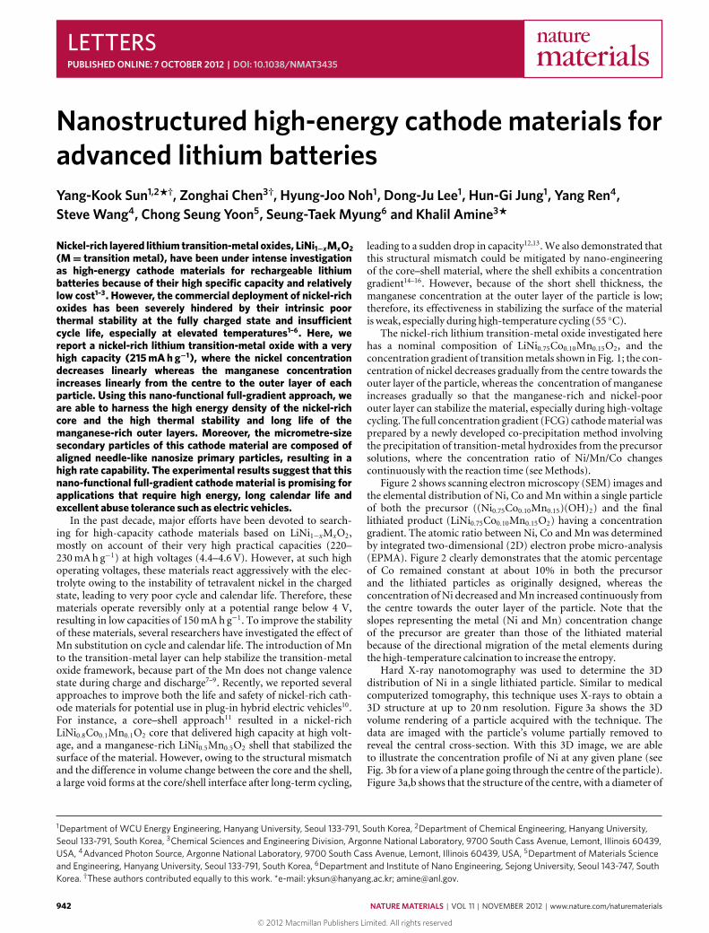
The nickel-rich lithium transition-metal oxide investigated herehas a nominal composition of LiNi0.75Co0.10Mn0.15O2, and theconcentration gradient of transitionmetals shown in Fig. 1; the con-centration of nickel decreases gradually from the centre towards theouter layer of the particle, whereas the concentration of manganeseincreases gradually so that the manganese-rich and nickel-poorouter layer can stabilize the material, especially during high-voltagecycling. The full concentration gradient (FCG) cathodematerial wasprepared by a newly developed co-precipitation method involvingthe precipitation of transition-metal hydroxides from the precursorsolutions, where the concentration ratio of Ni/Mn/Co changescontinuously with the reaction time (seeMethods).
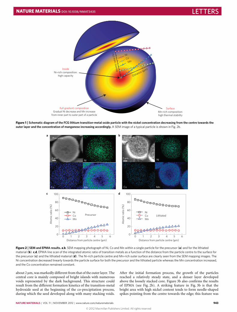
Figure 2 shows scanning electronmicroscopy (SEM) images andthe elemental distribution of Ni, Co andMn within a single particleof both the precursor ((Ni0.75Co0.10Mn0.15)(OH)2) and the finallithiated product (LiNi0.75Co0.10Mn0.15O2) having a concentrationgradient. The atomic ratio between Ni, Co andMn was determinedby integrated two-dimensional (2D) electron probe micro-analysis(EPMA). Figure 2 clearly demonstrates that the atomic percentageof Co remained constant at about 10% in both the precursorand the lithiated particles as originally designed, whereas theconcentration of Ni decreased andMn increased continuously fromthe centre towards the outer layer of the particle. Note that theslopes representing the metal (Ni and Mn) concentration changeof the precursor are greater than those of the lithiated materialbecause of the directional migration of the metal elements duringthe high-temperature calcination to increase the entropy.
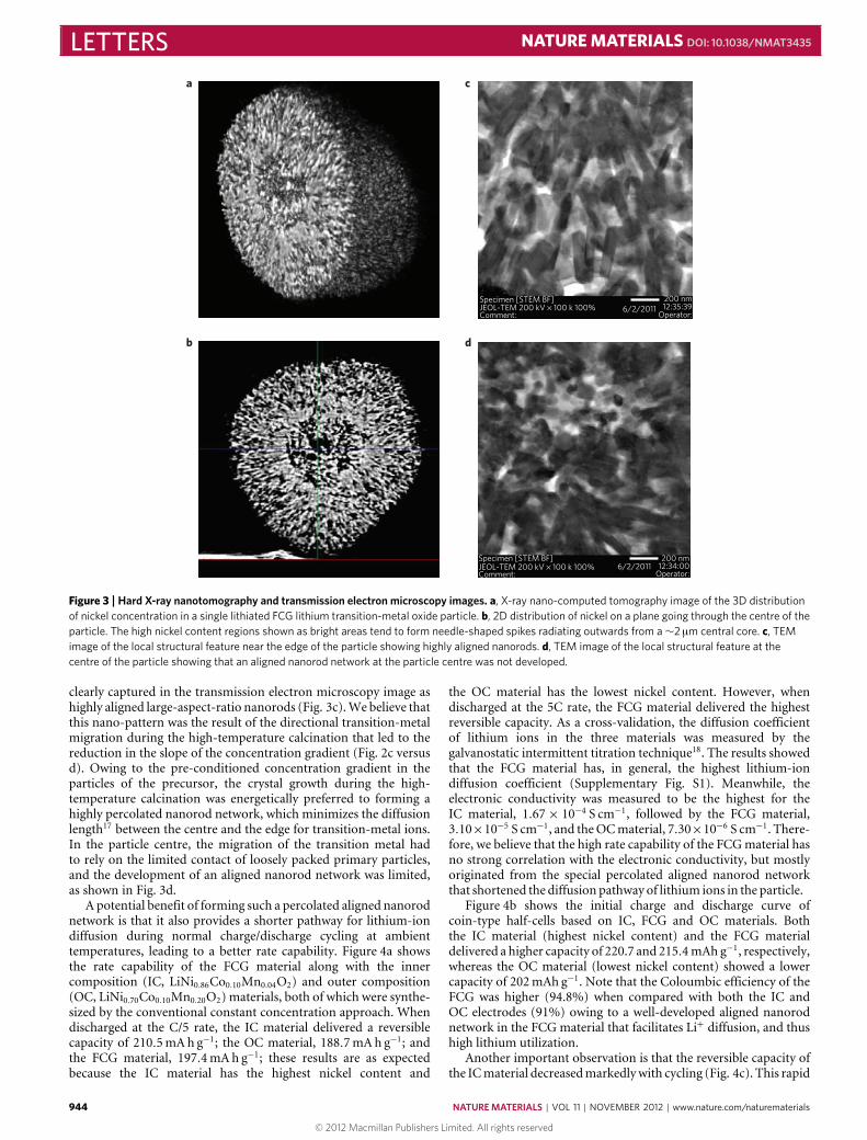
Hard X-ray nanotomography was used to determine the 3Ddistribution of Ni in a single lithiated particle. Similar to medicalcomputerized tomography, this technique uses X-rays to obtain a3D structure at up to 20 nm resolution. Figure 3a shows the 3Dvolume rendering of a particle acquired with the technique. Thedata are imaged with the particle’s volume partially removed toreveal the central cross-section. With this 3D image, we are ableto illustrate the concentration profile of Ni at any given plane (seeFig. 3b for a view of a plane going through the centre of the particle).Figure 3a,b shows that the structure of the centre, with a diameter of
Figure 1 | Schematic diagram of the FCG lithium transition-metal oxide particle with the nickel concentration decreasing from the centre towards theouter layer and the concentration of manganese increasing accordingly. A SEM image of a typical particle is shown in Fig. 2b.
Ni
b
c
Lithiated
Lithiated
2 µm
Co Mn
Precursor
80
60
40
20
1 2 3 54
Ato
mic
rat
io (
%)
0
100
Distance from particle centre (µm)0 6
NiCoMn
d
80
60
40
20
Ato
mic
rat
io (
%)
0
100
Distance from particle centre (µm)
NiCoMn
1 2 3 540 6
aPrecursor
2 µmNi
Co Mn
Figure 2 | SEM and EPMA results. a,b, SEM mapping photograph of Ni, Co and Mn within a single particle for the precursor (a) and for the lithiatedmaterial (b). c,d, EPMA line scan of the integrated atomic ratio of transition metals as a function of the distance from the particle centre to the surface forthe precursor (c) and the lithiated material (d). The Ni-rich particle centre and Mn-rich outer surface are clearly seen from the SEM mapping images. TheNi concentration decreased linearly towards the particle surface for both the precursor and the lithiated particle whereas the Mn concentration increased,and the Co concentration remained constant.
about 2 µm,wasmarkedly different from that of the outer layer. Thecentral core is mainly composed of bright islands with numerousvoids represented by the dark background. This structure couldresult from the different formation kinetics of the transition-metalhydroxide seed at the beginning of the co-precipitation process,during which the seed developed along with many stacking voids.
After the initial formation process, the growth of the particlesreached a relatively steady state, and a denser layer developedabove the loosely stacked core. Figure 3b also confirms the resultsof EPMA (see Fig. 2b). A striking feature in Fig. 3b is that thebright area with high nickel content tends to form needle-shapedspikes pointing from the centre towards the edge; this feature was
Specimen [STEM BF]JEOL-TEM 200 kV × 100 k 100%Comment:
Specimen [STEM BF]JEOL-TEM 200 kV × 100 k 100%Comment:
200 nm12:34:00
Operator:
Figure 3 |Hard X-ray nanotomography and transmission electron microscopy images. a, X-ray nano-computed tomography image of the 3D distributionof nickel concentration in a single lithiated FCG lithium transition-metal oxide particle. b, 2D distribution of nickel on a plane going through the centre of theparticle. The high nickel content regions shown as bright areas tend to form needle-shaped spikes radiating outwards from a∼2 µm central core. c, TEMimage of the local structural feature near the edge of the particle showing highly aligned nanorods. d, TEM image of the local structural feature at thecentre of the particle showing that an aligned nanorod network at the particle centre was not developed.
clearly captured in the transmission electron microscopy image ashighly aligned large-aspect-ratio nanorods (Fig. 3c).We believe thatthis nano-pattern was the result of the directional transition-metalmigration during the high-temperature calcination that led to thereduction in the slope of the concentration gradient (Fig. 2c versusd). Owing to the pre-conditioned concentration gradient in theparticles of the precursor, the crystal growth during the high-temperature calcination was energetically preferred to forming ahighly percolated nanorod network, which minimizes the diffusionlength17 between the centre and the edge for transition-metal ions.In the particle centre, the migration of the transition metal hadto rely on the limited contact of loosely packed primary particles,and the development of an aligned nanorod network was limited,as shown in Fig. 3d.
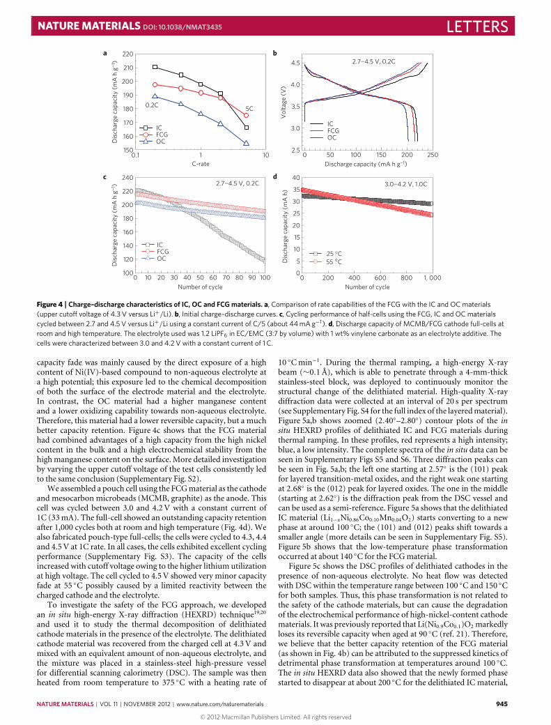
A potential benefit of forming such a percolated aligned nanorodnetwork is that it also provides a shorter pathway for lithium-iondiffusion during normal charge/discharge cycling at ambienttemperatures, leading to a better rate capability. Figure 4a showsthe rate capability of the FCG material along with the innercomposition (IC, LiNi0.86Co0.10Mn0.04O2) and outer composition(OC, LiNi0.70Co0.10Mn0.20O2) materials, both of which were synthe-sized by the conventional constant concentration approach. Whendischarged at the C/5 rate, the IC material delivered a reversiblecapacity of 210.5mAh g−1; the OC material, 188.7mAh g−1; andthe FCG material, 197.4mAh g−1; these results are as expectedbecause the IC material has the highest nickel content and
the OC material has the lowest nickel content. However, whendischarged at the 5C rate, the FCG material delivered the highestreversible capacity. As a cross-validation, the diffusion coefficientof lithium ions in the three materials was measured by thegalvanostatic intermittent titration technique18. The results showedthat the FCG material has, in general, the highest lithium-iondiffusion coefficient (Supplementary Fig. S1). Meanwhile, theelectronic conductivity was measured to be the highest for theIC material, 1.67× 10⁻⁴ S cm−1, followed by the FCG material,3.10×10−5 S cm−1, and theOCmaterial, 7.30×10⁻⁶ S cm−1. There-fore, we believe that the high rate capability of the FCGmaterial hasno strong correlation with the electronic conductivity, but mostlyoriginated from the special percolated aligned nanorod networkthat shortened the diffusion pathway of lithium ions in the particle.
Figure 4b shows the initial charge and discharge curve ofcoin-type half-cells based on IC, FCG and OC materials. Boththe IC material (highest nickel content) and the FCG materialdelivered a higher capacity of 220.7 and 215.4mAh g−1, respectively,whereas the OC material (lowest nickel content) showed a lowercapacity of 202mAh g−1. Note that the Coloumbic efficiency of theFCG was higher (94.8%) when compared with both the IC andOC electrodes (91%) owing to a well-developed aligned nanorodnetwork in the FCG material that facilitates Li+ diffusion, and thushigh lithium utilization.
Another important observation is that the reversible capacity ofthe ICmaterial decreasedmarkedlywith cycling (Fig. 4c). This rapid
Figure 4 | Charge–discharge characteristics of IC, OC and FCG materials. a, Comparison of rate capabilities of the FCG with the IC and OC materials(upper cutoff voltage of 4.3 V versus Li+/Li). b, Initial charge–discharge curves. c, Cycling performance of half-cells using the FCG, IC and OC materialscycled between 2.7 and 4.5 V versus Li+/Li using a constant current of C/5 (about 44 mA g−1). d, Discharge capacity of MCMB/FCG cathode full-cells atroom and high temperature. The electrolyte used was 1.2 LiPF6 in EC/EMC (3:7 by volume) with 1 wt% vinylene carbonate as an electrolyte additive. Thecells were characterized between 3.0 and 4.2 V with a constant current of 1 C.
capacity fade was mainly caused by the direct exposure of a highcontent of Ni(IV)-based compound to non-aqueous electrolyte ata high potential; this exposure led to the chemical decompositionof both the surface of the electrode material and the electrolyte.In contrast, the OC material had a higher manganese contentand a lower oxidizing capability towards non-aqueous electrolyte.Therefore, this material had a lower reversible capacity, but a muchbetter capacity retention. Figure 4c shows that the FCG materialhad combined advantages of a high capacity from the high nickelcontent in the bulk and a high electrochemical stability from thehighmanganese content on the surface. More detailed investigationby varying the upper cutoff voltage of the test cells consistently ledto the same conclusion (Supplementary Fig. S2).
We assembled a pouch cell using the FCGmaterial as the cathodeand mesocarbon microbeads (MCMB, graphite) as the anode. Thiscell was cycled between 3.0 and 4.2 V with a constant current of1C (33mA). The full-cell showed an outstanding capacity retentionafter 1,000 cycles both at room and high temperature (Fig. 4d). Wealso fabricated pouch-type full-cells; the cells were cycled to 4.3, 4.4and 4.5 V at 1C rate. In all cases, the cells exhibited excellent cyclingperformance (Supplementary Fig. S3). The capacity of the cellsincreased with cutoff voltage owing to the higher lithium utilizationat high voltage. The cell cycled to 4.5 V showed very minor capacityfade at 55 ◦C possibly caused by a limited reactivity between thecharged cathode and the electrolyte.
To investigate the safety of the FCG approach, we developedan in situ high-energy X-ray diffraction (HEXRD) technique19,20and used it to study the thermal decomposition of delithiatedcathode materials in the presence of the electrolyte. The delithiatedcathode material was recovered from the charged cell at 4.3 V andmixed with an equivalent amount of non-aqueous electrolyte, andthe mixture was placed in a stainless-steel high-pressure vesselfor differential scanning calorimetry (DSC). The sample was thenheated from room temperature to 375 ◦C with a heating rate of
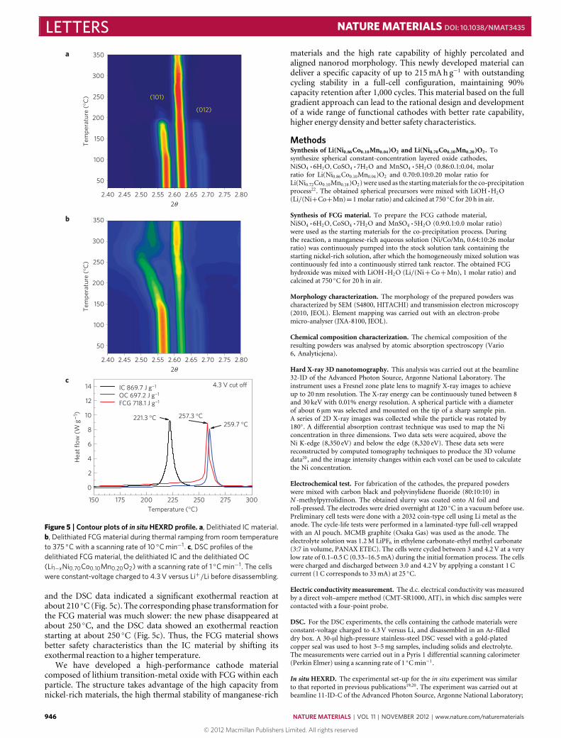
10 ◦Cmin−1. During the thermal ramping, a high-energy X-raybeam (∼0.1Å), which is able to penetrate through a 4-mm-thickstainless-steel block, was deployed to continuously monitor thestructural change of the delithiated material. High-quality X-raydiffraction data were collected at an interval of 20 s per spectrum(see Supplementary Fig. S4 for the full index of the layeredmaterial).Figure 5a,b shows zoomed (2.40◦–2.80◦) contour plots of the insitu HEXRD profiles of delithiated IC and FCG materials duringthermal ramping. In these profiles, red represents a high intensity;blue, a low intensity. The complete spectra of the in situ data can beseen in Supplementary Figs S5 and S6. Three diffraction peaks canbe seen in Fig. 5a,b; the left one starting at 2.57◦ is the (101) peakfor layered transition-metal oxides, and the right weak one startingat 2.68◦ is the (012) peak for layered oxides. The one in the middle(starting at 2.62◦) is the diffraction peak from the DSC vessel andcan be used as a semi-reference. Figure 5a shows that the delithiatedIC material (Li1−xNi0.86Co0.10Mn0.04O2) starts converting to a newphase at around 100 ◦C; the (101) and (012) peaks shift towards asmaller angle (more details can be seen in Supplementary Fig. S5).Figure 5b shows that the low-temperature phase transformationoccurred at about 140 ◦C for the FCGmaterial.
Figure 5c shows the DSC profiles of delithiated cathodes in thepresence of non-aqueous electrolyte. No heat flow was detectedwith DSC within the temperature range between 100 ◦C and 150 ◦Cfor both samples. Thus, this phase transformation is not related tothe safety of the cathode materials, but can cause the degradationof the electrochemical performance of high-nickel-content cathodematerials. It was previously reported that Li(Ni0.9Co0.1)O2 markedlyloses its reversible capacity when aged at 90 ◦C (ref. 21). Therefore,we believe that the better capacity retention of the FCG material(as shown in Fig. 4b) can be attributed to the suppressed kinetics ofdetrimental phase transformation at temperatures around 100 ◦C.The in situ HEXRD data also showed that the newly formed phasestarted to disappear at about 200 ◦C for the delithiated IC material,
Figure 5 | Contour plots of in situ HEXRD profile. a, Delithiated IC material.b, Delithiated FCG material during thermal ramping from room temperatureto 375 ◦C with a scanning rate of 10 ◦C min−1. c, DSC profiles of thedelithiated FCG material, the delithiated IC and the delithiated OC(Li1−xNi0.70Co0.10Mn0.20O2) with a scanning rate of 1 ◦C min−1. The cellswere constant-voltage charged to 4.3 V versus Li+/Li before disassembling.
and the DSC data indicated a significant exothermal reaction atabout 210 ◦C (Fig. 5c). The corresponding phase transformation forthe FCG material was much slower: the new phase disappeared atabout 250 ◦C, and the DSC data showed an exothermal reactionstarting at about 250 ◦C (Fig. 5c). Thus, the FCG material showsbetter safety characteristics than the IC material by shifting itsexothermal reaction to a higher temperature.
We have developed a high-performance cathode materialcomposed of lithium transition-metal oxide with FCG within eachparticle. The structure takes advantage of the high capacity fromnickel-rich materials, the high thermal stability of manganese-rich
materials and the high rate capability of highly percolated andaligned nanorod morphology. This newly developed material candeliver a specific capacity of up to 215mAh g−1 with outstandingcycling stability in a full-cell configuration, maintaining 90%capacity retention after 1,000 cycles. This material based on the fullgradient approach can lead to the rational design and developmentof a wide range of functional cathodes with better rate capability,higher energy density and better safety characteristics.
MethodsSynthesis of Li(Ni0.86Co0.10Mn0.04)O2 and Li(Ni0.70Co0.10Mn0.20)O2. Tosynthesize spherical constant-concentration layered oxide cathodes,NiSO4 ·6H2O,CoSO4 ·7H2O and MnSO4 ·5H2O (0.86:0.1:0.04, molarratio for Li(Ni0.86Co0.10Mn0.04)O2 and 0.70:0.10:0.20 molar ratio forLi(Ni0.72Co0.10Mn0.18)O2) were used as the startingmaterials for the co-precipitationprocess22. The obtained spherical precursors were mixed with LiOH ·H2O(Li/(Ni+Co+Mn)=1molar ratio) and calcined at 750 ◦C for 20 h in air.
Synthesis of FCG material. To prepare the FCG cathode material,NiSO4 ·6H2O,CoSO4 ·7H2O and MnSO4 ·5H2O (0.9:0.1:0.0 molar ratio)were used as the starting materials for the co-precipitation process. Duringthe reaction, a manganese-rich aqueous solution (Ni/Co/Mn, 0.64:10:26 molarratio) was continuously pumped into the stock solution tank containing thestarting nickel-rich solution, after which the homogeneously mixed solution wascontinuously fed into a continuously stirred tank reactor. The obtained FCGhydroxide was mixed with LiOH ·H2O (Li/(Ni+Co+Mn), 1 molar ratio) andcalcined at 750 ◦C for 20 h in air.
Morphology characterization. The morphology of the prepared powders wascharacterized by SEM (S4800, HITACHI) and transmission electron microscopy(2010, JEOL). Element mapping was carried out with an electron-probemicro-analyser (JXA-8100, JEOL).
Chemical composition characterization. The chemical composition of theresulting powders was analysed by atomic absorption spectroscopy (Vario6, Analyticjena).
Hard X-ray 3D nanotomography. This analysis was carried out at the beamline32-ID of the Advanced Photon Source, Argonne National Laboratory. Theinstrument uses a Fresnel zone plate lens to magnify X-ray images to achieveup to 20 nm resolution. The X-ray energy can be continuously tuned between 8and 30 keV with 0.01% energy resolution. A spherical particle with a diameterof about 6 µm was selected and mounted on the tip of a sharp sample pin.A series of 2D X-ray images was collected while the particle was rotated by180◦. A differential absorption contrast technique was used to map the Niconcentration in three dimensions. Two data sets were acquired, above theNi K-edge (8,350 eV) and below the edge (8,320 eV). These data sets werereconstructed by computed tomography techniques to produce the 3D volumedata20, and the image intensity changes within each voxel can be used to calculatethe Ni concentration.
Electrochemical test. For fabrication of the cathodes, the prepared powderswere mixed with carbon black and polyvinylidene fluoride (80:10:10) inN -methylpyrrolidinon. The obtained slurry was coated onto Al foil androll-pressed. The electrodes were dried overnight at 120 ◦C in a vacuum before use.Preliminary cell tests were done with a 2032 coin-type cell using Li metal as theanode. The cycle-life tests were performed in a laminated-type full-cell wrappedwith an Al pouch. MCMB graphite (Osaka Gas) was used as the anode. Theelectrolyte solution was 1.2M LiPF6 in ethylene carbonate-ethyl methyl carbonate(3:7 in volume, PANAX ETEC). The cells were cycled between 3 and 4.2 V at a verylow rate of 0.1–0.5 C (0.33–16.5mA) during the initial formation process. The cellswere charged and discharged between 3.0 and 4.2 V by applying a constant 1 Ccurrent (1 C corresponds to 33mA) at 25 ◦C.
Electric conductivitymeasurement. The d.c. electrical conductivity was measuredby a direct volt–ampere method (CMT-SR1000, AIT), in which disc samples werecontacted with a four-point probe.
DSC. For the DSC experiments, the cells containing the cathode materials wereconstant-voltage charged to 4.3 V versus Li, and disassembled in an Ar-filleddry box. A 30-µl high-pressure stainless-steel DSC vessel with a gold-platedcopper seal was used to host 3–5mg samples, including solids and electrolyte.The measurements were carried out in a Pyris 1 differential scanning calorimeter(Perkin Elmer) using a scanning rate of 1 ◦Cmin−1.
In situHEXRD. The experimental set-up for the in situ experiment was similarto that reported in previous publications19,20. The experiment was carried out atbeamline 11-ID-C of the Advanced Photon Source, Argonne National Laboratory;
NATURE MATERIALS DOI: 10.1038/NMAT3435 LETTERSthe X-ray wavelength was 0.10798Å. A DSC sample contained in a high-pressurestainless-steel vessel was placed vertically in a programmable thermal stage, and thesample was heated up to 350 ◦C with a constant heating rate of 10 ◦C per minute.During the course of thermal ramping, high-energy X-rays penetrated through thesample horizontally, and a Perkin Elmer area detector was used to collect the X-raydiffraction patterns in the transmission geometry with a spectrum data collectionrate of one pattern every 20 s. The collected 2D patterns were then integrated intoconventional 1D data (intensity versus 2θ) using the fit2d program23.
Received 16 February 2012; accepted 27 August 2012;published online 7 October 2012
References1. Dunn, B., Kamath, H. & Tarascon, J. M. Electrical energy storage for the grid:
A battery of choices. Science 334, 928–935 (2011).2. Liu, C., Li, F., Ma, L. P. & Cheng, H. M. Advanced materials for energy storage.
Adv. Mater. 22, E28–E62 (2010).3. Scrosati, B. & Garche, J. Lithium batteries: Status, prospects and future.
J. Power Sources 195, 2419–2430 (2010).4. Goodenough, J. B. & Kim, Y. Challenges for rechargeable Li batteries.
Chem. Mater. 22, 587–603 (2010).5. Etacheri, V., Marom, R., Elazari, R., Salitra, G. & Aurbach, D. Challenges in
the development of advanced Li-ion batteries: A review. Energ. Environ. Sci. 4,3243–3262 (2011).
6. Bandhauer, T. M., Garimella, S. & Fuller, T. F. A critical review of thermalissues in lithium–ion batteries. J. Electrochem. Soc. 158, R1–R25 (2011).
7. MacNeil, D. D., Lu, Z. & Dahn, J. R. Structure and electrochemistryof Li[NixCo1−2xMnx]O2 (0<= x <= 1/2). J. Electrochem. Soc. 149,A1332–A1336 (2002).
8. Hwang, B. J., Tsai, Y. W., Carlier, D. & Ceder, G. A combinedcomputational/experimental study on Li[Ni1/3Co1/3Mn1/3]O2. Chem.Mater. 15, 3676–3682 (2003).
9. Kim,M. G., Shin, H. J., Kim, J. H., Park, S. H. & Sun, Y. K. XAS investigation ofinhomogeneous metal-oxygen bond covalency in bulk and surface for chargecompensation in Li-ion battery cathode Li[Ni1/3Co1/3Mn1/3]O2 material.J. Electrochem. Soc. 152, A1320–A1328 (2005).
10. Chen, Z. H., Lee, D. J., Sun, Y-K. & Amine, K. Advanced cathode materials forlithium–ion batteries.Mater. Res. Soc. Bull. 36, 498–505 (2011).
11. Sun, Y-K. et al. Synthesis and characterization ofLi[(Ni0.8Co0.1Mn0.1)0.8(Ni0.5Mn0.5)0.2]O2 with the microscale core-shellstructure as the positive electrode material for lithium batteries. J. Am. Chem.Soc. 127, 13411–13418 (2005).
12. Sun, Y-K., Myung, S-T., Park, B-C. & Amine, K. Synthesis of spherical nano-to microscale core-shell particles Li[(Ni0.8Co0.1Mn0.1)1−x(Ni0.5Mn0.5)x]O2 andtheir applications to lithium batteries. Chem. Mater. 18, 5199–5163 (2006).
13. Sun, Y-K. et al. Novel core-shell-structured Li[(Ni0.8Co0.2)0.8(Ni0.5Mn0.5)0.2]O2
via coprecipitation as positive electrode material for lithium secondarybatteries. J. Phys. Chem. B 110, 6810–6815 (2006).
14. Sun, Y-K. et al. High-energy cathode material for long-life and safe lithiumbatteries. Nature Mater. 8, 320–324 (2009).
15. Sun, Y-K. et al. A novel cathode material with a concentration-gradientfor high-energy and safe lithium–ion batteries. Adv. Funct. Mater. 20,485–491 (2010).
16. Sun, Y-K. et al. A novel concentration-gradient Li[Ni0.83Co0.07Mn0.10]O2
cathode material for high-energy lithium–ion batteries. J. Mater. Chem. 21,10108–10112 (2011).
17. Berhan, L. & Sastry, A. M. Modeling percolation in high-aspect-ratio fibersystems. II. The effect of waviness on the percolation onset. Phys. Rev. E 75,041121–041127 (2007).
18. Shaju, K. M., Rao, G. V. S. & Chowdari, B. V. R. Li ion kinetic studies onspinel cathodes, Li(M1/6Mn11/6)O4 (M=Mn, Co, CoAl) by GITT and EIS.J. Mater. Chem. 13, 106–113 (2003).
19. Chen, Z. H. et al. Solid state synthesis of LiFePO4 studied by in situ high energyX-ray diffraction. J. Mater. Chem. 21, 5604–5609 (2011).
20. Chen, Z. H. et al. Multi-scale study of thermal stability of lithiated graphite.Energ. Environ. Sci. 4, 4023–4030 (2011).
21. Ahn, D. et al. Suppression of structural degradation of LiNi0.9Co0.1O2 cathodeat 90 ◦C by AlPO4-nanoparticle coating. Current Appl. Phys. 7, 172–175 (2007).
23. Hammersley, A. P., Svensson, S. O., Hanfland, M., Fitch, A. N. & Hausermann,D. Two-dimensional detector software: From real detector to idealised imageor two-theta scan. High Pressure Res. 14, 235–248 (1996).
AcknowledgementsThis work was supported by the Human Resources Development of the Korea Instituteof Energy Technology Evaluation and Planning (KETEP) grant funded by the Koreagovernment Ministry of Knowledge Economy (No. 20114010203150) and the NationalResearch Foundation of KOREA (NRF) grant funded by the Korea government (MEST;No. 2009-0092780). Research at Argonne National Laboratory was funded by theUS Department of Energy, EERE Vehicle Technologies Program. Argonne NationalLaboratory is operated for the US Department of Energy by UChicago Argonne,LLC, under contract DE-AC02-06CH11357. The authors also acknowledge the use ofthe Advanced Photon Source of Argonne National Laboratory supported by the USDepartment of Energy, Office of Science, Office of Basic Energy Sciences.
Author contributionsY-K.S. and K.A. proposed the concept. Z.C., H-J.N., D-J.L., H-G.J., S-T.M., C.S.Y.,Y.R. and S.W. performed the experiments and acquired the data. Y-K.S., Z.C. andK.A. wrote the paper.
Additional informationSupplementary information is available in the online version of the paper. Reprints andpermissions information is available online at www.nature.com/reprints. Correspondenceand requests for materials should be addressed to Y-K.S. or K.A.
Competing financial interestsThe authors declare no competing financial interests.