SANDIA REPORT SAND2010-7086 Unlimited Release November 2010 Nanostructured Material for Advanced Energy Storage -- Magnesium Battery Cathode Development Nelson S. Bell, Ganesh Nagasubramanian, Sandia National Laboratories Karren (Chris) V. Woan, Wolfgang M. Sigmund University of Florida Prepared by Sandia National Laboratories Albuquerque, New Mexico 87185 and Livermore, California 94550 Sandia National Laboratories is a multi-program laboratory managed and operated by Sandia Corporation, a wholly owned subsidiary of Lockheed Martin Corporation, for the U.S. Department of Energy's National Nuclear Security Administration under contract DE-AC04-94AL85000. Approved for public release; further dissemination unlimited.
Transcript
SANDIA REPORT SAND2010-7086 Unlimited Release November 2010
Nanostructured Material for Advanced Energy Storage -- Magnesium Battery Cathode Development Nelson S. Bell, Ganesh Nagasubramanian, Sandia National Laboratories Karren (Chris) V. Woan, Wolfgang M. Sigmund University of Florida Prepared by Sandia National Laboratories Albuquerque, New Mexico 87185 and Livermore, California 94550
Sandia National Laboratories is a multi-program laboratory managed and operated by Sandia Corporation, a wholly owned subsidiary of Lockheed Martin Corporation, for the U.S. Department of Energy's National Nuclear Security Administration under contract DE-AC04-94AL85000. Approved for public release; further dissemination unlimited.
2
Issued by Sandia National Laboratories, operated for the United States Department of Energy by Sandia Corporation. NOTICE: This report was prepared as an account of work sponsored by an agency of the United States Government. Neither the United States Government, nor any agency thereof, nor any of their employees, nor any of their contractors, subcontractors, or their employees, make any warranty, express or implied, or assume any legal liability or responsibility for the accuracy, completeness, or usefulness of any information, apparatus, product, or process disclosed, or represent that its use would not infringe privately owned rights. Reference herein to any specific commercial product, process, or service by trade name, trademark, manufacturer, or otherwise, does not necessarily constitute or imply its endorsement, recommendation, or favoring by the United States Government, any agency thereof, or any of their contractors or subcontractors. The views and opinions expressed herein do not necessarily state or reflect those of the United States Government, any agency thereof, or any of their contractors. Printed in the United States of America. This report has been reproduced directly from the best available copy. Available to DOE and DOE contractors from U.S. Department of Energy Office of Scientific and Technical Information P.O. Box 62 Oak Ridge, TN 37831 Telephone: (865) 576-8401 Facsimile: (865) 576-5728 E-Mail: [email protected] Online ordering: http://www.osti.gov/bridge Available to the public from U.S. Department of Commerce National Technical Information Service 5285 Port Royal Rd. Springfield, VA 22161 Telephone: (800) 553-6847 Facsimile: (703) 605-6900 E-Mail: [email protected] Online order: http://www.ntis.gov/help/ordermethods.asp?loc=7-4-0#online
3
SAND2010-7086 Unlimited Release
Printed November 2010
Nanostructured Material for Advanced Energy Storage -- Magnesium Battery Cathode
Development
Nelson S. Bell Electronic Materials and Nanostructures
Sandia National Laboratories P.O. Box 5800
Albuquerque, New Mexico 87185-MS1411
Karran V. Woan and Wolfgang M. Sigmund Materials Science and Engineering Dept.
University of Florida 100 Rhines Hall P.O. Box 116400
Gainesville, FL 32601-7845
Abstract
Magnesium batteries are alternatives to the use of lithium ion and nickel metal hydride secondary batteries due to magnesium’s abundance, safety of operation, and lower toxicity of disposal. The divalency of the magnesium ion and its chemistry poses some difficulties for its general and industrial use. This work developed a continuous and fibrous nanoscale network of the cathode material through the use of electrospinning with the goal of enhancing performance and reactivity of the battery. The system was characterized and preliminary tests were performed on the constructed battery cells. We were successful in building and testing a series of electrochemical systems that demonstrated good cyclability maintaining 60-70% of discharge capacity after more than 50 charge-discharge cycles.
4
ACKNOWLEDGMENTS We would like to thank the NINE Program for funding the Sandia Fellowship program with the University of Florida, and to the Wolfgang Sigmund group in the Materials Science and Engineering Department for their participation in this program. Their relationship with our work has been particularly enjoyable and productive. Sandia is a multiprogram laboratory operated by Sandia Corporation, a Lockheed Martin Company, for the United States Department of Energy's National Nuclear Security Administration under contract DE-AC04-94AL85000.
5
CONTENTS
Nanostructured Material for Advanced Energy Storage -- Magnesium Battery Cathode Development ................................................................................................................................... 3
Distribution ................................................................................................................................... 22
FIGURES Figure 1. Digital photograph of a cathode composed of electrospun, Chevrel phase Mg2Mo6S8 loaded carbon fibers. The green fibers were punched into ¾” disks that shrank down to approximately ½” during heat treatment. ..................................................................................... 11 Figure 2. TEM micrograph of Electrospun Mg2Mo6S8 fiber, right, and SAD pattern indicating Mg2Mo6S8 was synthesized. ......................................................................................................... 12 Figure 3. XRD patterns of a sample of Mg2Mo6S8 in carbonized PAN. Both scans were of samples from the same run. The top scan was a slower scan of 0.02 o/s and the lower scan rate was 0.04o/s. The sample in the top scan was ground with a mortar and pestle and fixed in epoxy, while the sample in the lower scan was untreated and was merely taped to a glass slide. The broad peak between 15o-30o is typical of carbonized PAN. It is difficult to attribute the other peaks to Mg2Mo6S8 with confidence. ........................................................................................... 12 Figure 4. XRD pattern of a sample Mg2Mo6S8 sample prepared without PAN. It should be noted that this sample was prepared directly from a precursor solution without electrospinning. ......... 13 Figure 5. Manual and automatic crimping machines by Hohsen Corporation used to seal coin cells. .............................................................................................................................................. 14 Figure 6. Sample charge-discharge curves for a 5-cycle run with accompanying diagram of capacity fade. ................................................................................................................................ 15 Figure 7. Initial discharge capacity of the coin cells showing spread of capacity data. ............... 16
6
Figure 8. Capacity fade comparison over 5 cycles comparing the final capacity to the beginning of the linear discharge region ........................................................................................................ 17 Figure 9. Capacity fade comparison over 50 cycles comparing the final capacity to the first complete discharge cycle capacity. In the 50 cycle testing, the actual capacity trend appears to be logarithmic with cycling rather than having a clear linear region. ............................................... 18
7
NOMENCLATURE dB decibel DOE Department of Energy SNL Sandia National Laboratories
8
9
1. INTRODUCTION Advancement and research on the development of secondary, i.e. rechargeable, batteries
has become a hot topic due to the prevalence and ubiquity of mobile devices and the need for energy storage from renewable resources. Such metrics being sought after include increased recharge cycles, safety under punishing conditions, and low toxicity during disposal compared with lithium ion, lead acid, or nickel-cadmium batteries.
Magnesium-ion batteries show promise as an alternative. They have a high specific charge compared to materials beyond lithium and magnesium is abundantly present in nature. Further benefits result from decreased risk of exploding or overheating of the batteries since magnesium is relatively inert compared with lithium. Many challenges persist for the adoption of magnesium-based batteries primarily related to the prevention of surface film formation upon the magnesium anode, the volatility and anodic stability of electrolytes, and the development of cathodes with a high degree of magnesium intercalation and kinetics to yield high capacities (1). As a means of addressing these issues, electrolyte and cathode development continues and notable achievements have been made to address the challenges. The issues of film formation on the magnesium electrode which hinders magnesium ion conduction have been addressed by development of electrolytes which prevent the formation of surface films on magnesium. Currently, the most effective electrolytes have been the use of magnesium salt complexes in ethereal solvents which display good conductivity, have a wide electrochemical window, and allows for the deposition and dissolution of magnesium on the electrodes. Cathode development had lead to the use of Chevrel phases to impart kinetically favorable and reversible reactions for intercalation (insertion) and deintercation (removal) of magnesium ions, and having a theoretical capacity of 128 mAh/g (2-5).
To synthesize an active cathode Chevrel phase, there are a multitude of steps required. High temperature synthesis of 1000-1200 °C of the combined elements and sulfides results in a cation-stabilized phase, such as Cu2Mo6S8. The desired pure Chevrel phase is thermodynamically unstable and requires leaching out of the cation. Aurbach’s research group has demonstrated the preservation of the Chevrel phase during their leaching steps. Furthermore, they synthesized Mg2Mo6S8 directly, but the material had poor electrochemical activity which they believe is due to the presence of MgO surface formations (4, 6).
We proposed the usage of the electrospinning processing technique to directly produce continuous and fibrous networks of the Mg2Mo6S8 cathode material. This has the potential benefits of decreasing the heat treatment temperature, increasing electrochemical activity and conductivity due to the nanoscale of the fibers and the intimate integration of carbon into the fibrous matrix. Electrospinning precursors were determined, the cathode material was spun into a fiber mat, a die was used to punch out cathodes, and the cathodes were processed and subsequently assembled into a battery cell for testing. Short term (5 cycles) and long term (50 cycles) testing were completed on the batteries. Furthermore, temperature effects (25 °C vs 35 °C) on the capacity were examined.
10
11
2. MATERIALS AND METHODOLOGY
2.1 Electrospun Cathode Preparation In order to avoid the leaching of the copper step required to prepare the Cu2Mo6S8 Chevrel phase for magnesium intercalation, the direct preparation of Mg2Mo6S8 in a supporting matrix was attempted and the magnesium Chevrel phase was successfully obtained. Polymers such as polyvinyl alcohol (PVA) or polyvinylpyrrolidone (PVP) were frequently used in the electrospinning of lithium battery cathode materials. They aided in the coordination of the ceramic precursors during calcination. Unlike most other electrospun cathode materials, the Chevrel phase is not an oxide. Polymers and magnesium, molybdenum and sulfur precursors that contain oxygen were not used in the synthesis of Chevrel phase fibers to avoid the formation of oxides during the heat treatment. The electrospinning solutions consisted of N,N dimenthylformamide (DMF) with 5 wt% polyacrylonitrile and 0.01 M magnesium (II) chloride, 0.03 M molybdenum (V) chloride and 0.04 M thiourea (CH4N2S). The flow rate, working distance, and applied voltage will be 0.25 mL/hr, 10 cm, and 15 kV applied potential. The fibers were collected on a 12 cm diameter mandrel rotating at 300 rpm.
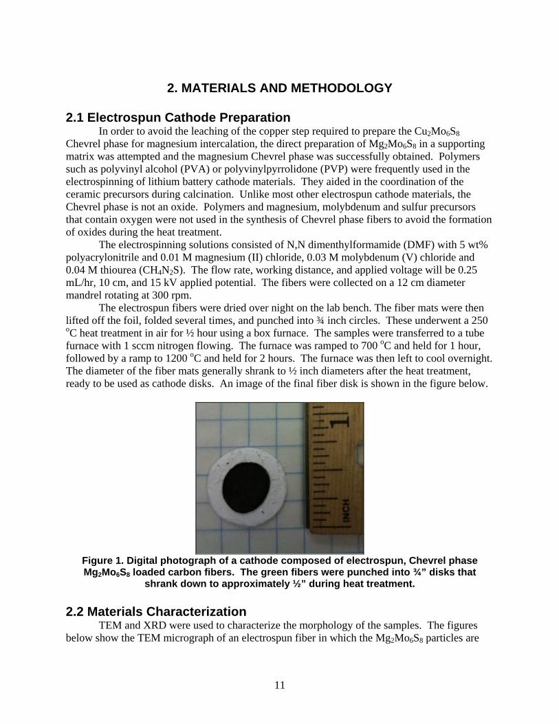
The electrospun fibers were dried over night on the lab bench. The fiber mats were then lifted off the foil, folded several times, and punched into ¾ inch circles. These underwent a 250 oC heat treatment in air for ½ hour using a box furnace. The samples were transferred to a tube furnace with 1 sccm nitrogen flowing. The furnace was ramped to 700 oC and held for 1 hour, followed by a ramp to 1200 oC and held for 2 hours. The furnace was then left to cool overnight. The diameter of the fiber mats generally shrank to ½ inch diameters after the heat treatment, ready to be used as cathode disks. An image of the final fiber disk is shown in the figure below.
Figure 1. Digital photograph of a cathode composed of electrospun, Chevrel phase Mg2Mo6S8 loaded carbon fibers. The green fibers were punched into ¾” disks that
shrank down to approximately ½” during heat treatment.
2.2 Materials Characterization
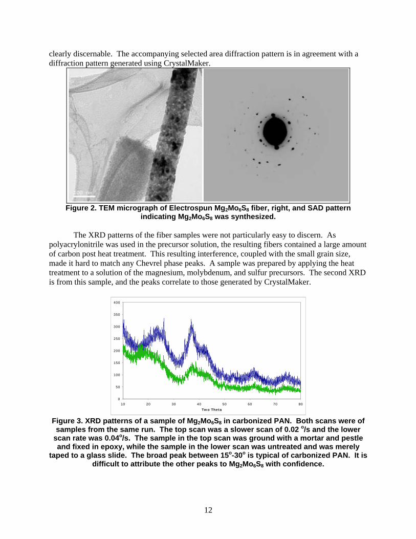
TEM and XRD were used to characterize the morphology of the samples. The figures below show the TEM micrograph of an electrospun fiber in which the Mg2Mo6S8 particles are
12
clearly discernable. The accompanying selected area diffraction pattern is in agreement with a diffraction pattern generated using CrystalMaker.
Figure 2. TEM micrograph of Electrospun Mg2Mo6S8 fiber, right, and SAD pattern
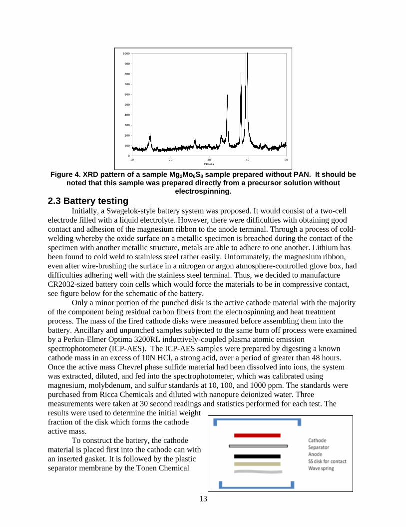
indicating Mg2Mo6S8 was synthesized. The XRD patterns of the fiber samples were not particularly easy to discern. As
polyacrylonitrile was used in the precursor solution, the resulting fibers contained a large amount of carbon post heat treatment. This resulting interference, coupled with the small grain size, made it hard to match any Chevrel phase peaks. A sample was prepared by applying the heat treatment to a solution of the magnesium, molybdenum, and sulfur precursors. The second XRD is from this sample, and the peaks correlate to those generated by CrystalMaker.
0
50
100
150
200
250
300
350
400
10 20 30 40 50 60 70 80
Two Theta
Figure 3. XRD patterns of a sample of Mg2Mo6S8 in carbonized PAN. Both scans were of samples from the same run. The top scan was a slower scan of 0.02 o/s and the lower
scan rate was 0.04o/s. The sample in the top scan was ground with a mortar and pestle and fixed in epoxy, while the sample in the lower scan was untreated and was merely
taped to a glass slide. The broad peak between 15o-30o is typical of carbonized PAN. It is difficult to attribute the other peaks to Mg2Mo6S8 with confidence.
13
0
100
200
300
400
500
600
700
800
900
1000
10 20 30 40 50
2theta
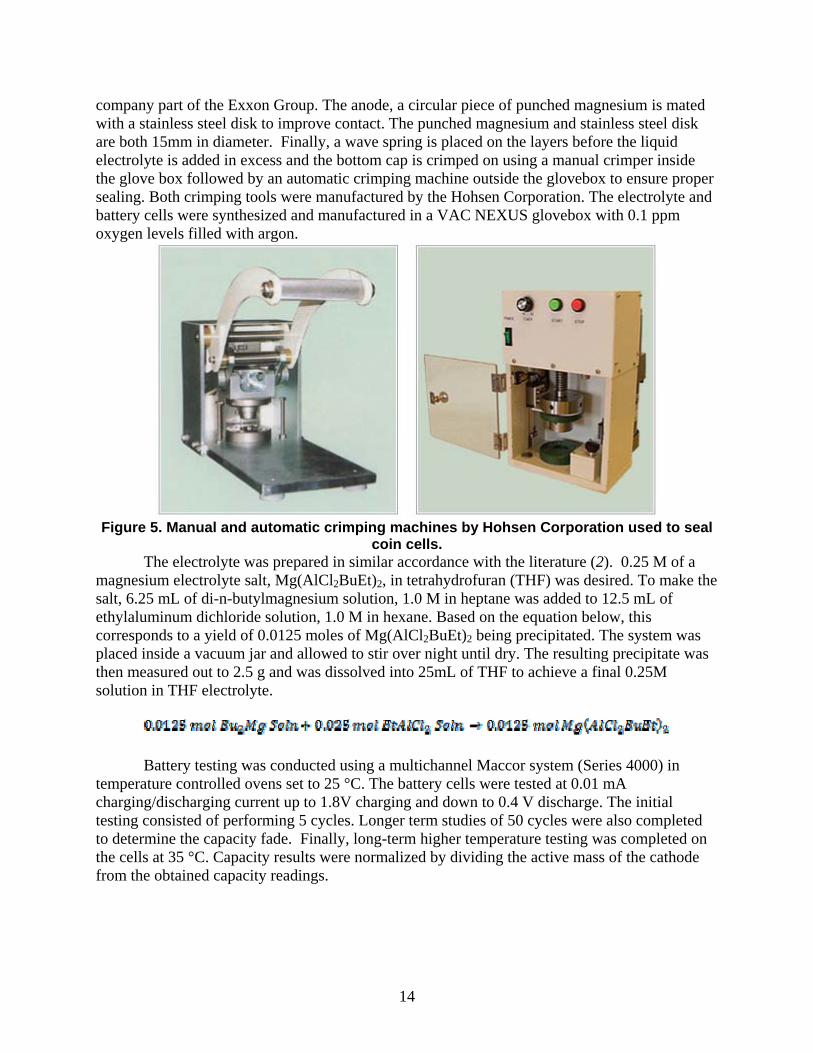
Figure 4. XRD pattern of a sample Mg2Mo6S8 sample prepared without PAN. It should be
noted that this sample was prepared directly from a precursor solution without electrospinning.
2.3 Battery testing Initially, a Swagelok-style battery system was proposed. It would consist of a two-cell
electrode filled with a liquid electrolyte. However, there were difficulties with obtaining good contact and adhesion of the magnesium ribbon to the anode terminal. Through a process of cold-welding whereby the oxide surface on a metallic specimen is breached during the contact of the specimen with another metallic structure, metals are able to adhere to one another. Lithium has been found to cold weld to stainless steel rather easily. Unfortunately, the magnesium ribbon, even after wire-brushing the surface in a nitrogen or argon atmosphere-controlled glove box, had difficulties adhering well with the stainless steel terminal. Thus, we decided to manufacture CR2032-sized battery coin cells which would force the materials to be in compressive contact, see figure below for the schematic of the battery.
Only a minor portion of the punched disk is the active cathode material with the majority of the component being residual carbon fibers from the electrospinning and heat treatment process. The mass of the fired cathode disks were measured before assembling them into the battery. Ancillary and unpunched samples subjected to the same burn off process were examined by a Perkin-Elmer Optima 3200RL inductively-coupled plasma atomic emission spectrophotometer (ICP-AES). The ICP-AES samples were prepared by digesting a known cathode mass in an excess of 10N HCl, a strong acid, over a period of greater than 48 hours. Once the active mass Chevrel phase sulfide material had been dissolved into ions, the system was extracted, diluted, and fed into the spectrophotometer, which was calibrated using magnesium, molybdenum, and sulfur standards at 10, 100, and 1000 ppm. The standards were purchased from Ricca Chemicals and diluted with nanopure deionized water. Three measurements were taken at 30 second readings and statistics performed for each test. The results were used to determine the initial weight fraction of the disk which forms the cathode active mass.
To construct the battery, the cathode material is placed first into the cathode can with an inserted gasket. It is followed by the plastic separator membrane by the Tonen Chemical
14
company part of the Exxon Group. The anode, a circular piece of punched magnesium is mated with a stainless steel disk to improve contact. The punched magnesium and stainless steel disk are both 15mm in diameter. Finally, a wave spring is placed on the layers before the liquid electrolyte is added in excess and the bottom cap is crimped on using a manual crimper inside the glove box followed by an automatic crimping machine outside the glovebox to ensure proper sealing. Both crimping tools were manufactured by the Hohsen Corporation. The electrolyte and battery cells were synthesized and manufactured in a VAC NEXUS glovebox with 0.1 ppm oxygen levels filled with argon.
Figure 5. Manual and automatic crimping machines by Hohsen Corporation used to seal
coin cells. The electrolyte was prepared in similar accordance with the literature (2). 0.25 M of a
magnesium electrolyte salt, Mg(AlCl2BuEt)2, in tetrahydrofuran (THF) was desired. To make the salt, 6.25 mL of di-n-butylmagnesium solution, 1.0 M in heptane was added to 12.5 mL of ethylaluminum dichloride solution, 1.0 M in hexane. Based on the equation below, this corresponds to a yield of 0.0125 moles of Mg(AlCl2BuEt)2 being precipitated. The system was placed inside a vacuum jar and allowed to stir over night until dry. The resulting precipitate was then measured out to 2.5 g and was dissolved into 25mL of THF to achieve a final 0.25M solution in THF electrolyte.
Battery testing was conducted using a multichannel Maccor system (Series 4000) in temperature controlled ovens set to 25 °C. The battery cells were tested at 0.01 mA charging/discharging current up to 1.8V charging and down to 0.4 V discharge. The initial testing consisted of performing 5 cycles. Longer term studies of 50 cycles were also completed to determine the capacity fade. Finally, long-term higher temperature testing was completed on the cells at 35 °C. Capacity results were normalized by dividing the active mass of the cathode from the obtained capacity readings.
15
3. RESULTS AND DISCUSSIONS 3.1 Battery testing
Three sets of batteries were tested to determine the cathode capacity and the capacity fade over multiple charge-discharge cycles. A sample of the voltage cycle test is shown below with accompanying charging and discharging capacity fade. The rest of the graphs can be found in the appendix. The capacity represents the area under the time to charge or time to discharge of the current graph. The initial discharge is usually longer than subsequent cycling due to the lower chemical mobility of the species. Initial magnesium ions are highly incorporated into the Chevrel phase cathode after synthesis. Current is required to drive the magnesium into the cathode. Subsequent discharge and charging cycles occur readily thus shifting the now mobile magnesium from electrode to electrode. This region is deemed to begin on cycle #2, corresponding to the first full discharge, and is termed the initial linear region because the subsequent discharges generally follow a linear trend.
The charge and discharge capacities were divided by the active mass determined from ICP. The active mass fraction of the cathode was found to be around 0.25. This was derived from the 203.845 nm Mo emission peak. The molybdenum peak was chosen due to its consistency of result for all emission lines, and the 203.845 nm peak was chosen for having the lowest standard deviation of the Mo emission lines. All the masses of the cathodes were multiplied by the 0.25 factor with the result representing the active mass. The active mass calculations represent the upper limit because it assumes the complete formation of the Chevrel phase.
Figure 6. Sample charge-discharge curves for a 5-cycle run with accompanying diagram
of capacity fade.
16
Figure 7. Initial discharge capacity of the coin cells showing spread of capacity data.
Unfortunately, the battery capacity measured fell below the theoretical capacity of 128.8
mAh/g. We were only able to achieve a value of at most 20% of theoretical and an average of about 10% of the theoretical capacity. Surface area had a significant role as the “A” batch exhibited quite uniform pellet-shaped geometries, whereas the “E” batteries had more of a brittle wafer-type macrostructure, with the “E” batteries exhibiting a wider range for capacity values. Aurbach’s group had success obtaining around 80% of the theoretical value using the Chevrel phase at cycling conditions of 0.5 – 1.7 V and having current densities about 25x higher than our tests. They attribute the performance of the Chevrel phase to the high level of delocalization of electrons in the structure thus enhancing the magnesium ion’s ability to change its oxidation state to intercalate into the structure. Another enhancement mechanism is based on the octahedral clusters formed by the molybdenums which can acquire four electrons at once and distribute them to the magnesium ions during intercalation (7). Levi et al. also looked at magnesium-chevrel phases synthesized by the high temperature route compared to those synthesized from the leaching of copper Chevrel phases and noted that the decrease in performance is believed to be from the formation of surface MgO which does not conduct magnesium ions (6).
The nanoscale structure of our electrospun Chevrel phase results in a high surface area and fibers which may react with any presence of oxygen to form MgO. During electrospinning or post heat treatment, any excess magnesium species on the surfaces might interact with oxygen leading to the oxide formation. Acid treatment could be used to remove MgO surface films, but this needs to be further explored. The fine grains might also lack the connectivity to effectively redistribute electrons during the intercalation or deintercalation process. Furthermore, the large degree of surface sites could cause the buildup of intercalated surface magnesium which through cation repulsion prevents the ability for subsequent cations to insert into the bulk. However, the fibrous nature of the cathode should allow for the electrolyte to penetrate into the macrostructure, so this might not be the dominating factor. Varying the heat treatment schedule to determine the effects on the grain size to the capacity or measuring the impurity concentrations and comparing them to the electrochemical performance might elucidate the actual mechanisms.
At the end of the five cycles, the average remaining capacity is about 65% of the initial linear region discharge capacity. Further testing of two of the cathodes, A1 and A3 for 50 cycles, the cathode exhibits a logarithmic trend, i.e. initial high capacity region decay followed by a modest linear decay region. This indicates that the cells are becoming more and more reversible,
17
and that there might be some initial contaminant surface films on the electrodes or other battery components which have decomposed over the cycling. On average, over the long cycle test, about 75% of the discharge capacity remained. These findings are exciting in that it suggests the cathodes to be quite reversible and exhibit little long term degradation.
Figure 8. Capacity fade comparison over 5 cycles comparing the final capacity to the
beginning of the linear discharge region Results for the higher temperature testing are also indicated below. Nearly all the 5 cells
tested exhibited similar discharge capacity decay trends as the previous 50 cycle testing. However, the remaining discharge capacity is decreased slightly to about 55% on average of the 5 cell with the highest being around 70% and the lowest at 35%. It must be noted that the same batch of “A” cells exhibited similar discharge properties even at the higher temperature, with a 66% average remaining discharge capacity compared to the first-full cycle initial discharge over the 50 cycle high temperature run. Higher temperatures may result in the degradation of the THF-based electrolyte decreasing the discharge capacity more rapidly than at lower temperatures.
18
Figure 9. Capacity fade comparison over 50 cycles comparing the final capacity to the
first complete discharge cycle capacity. In the 50 cycle testing, the actual capacity trend appears to be logarithmic with cycling rather than having a clear linear region.
19
4. CONCLUSIONS AND FUTURE OUTLOOK Overall, we were successful in implementing the electrospinning process to develope
cathodes with a high degree of cyclability. An electrospinning solution was prepared, the electrospun material characterized and then constructed into a working battery cell to determine its electrochemical properties. Long term stability was seen with a 66% remaining capacity after 50 cycles at high temperatures.
Further work needs to be undertaken to increase the active mass content of the electrospun material. Currently, the active mass content remains only 0.25 of the cathode disk. We also need to investigate the reasons why performance was significantly lower than the theoretical values. This includes determining the macrostructure effects such as the grain size of the magnesium-Chevrel phase on capacity, identifying the presence of surface films post storage or the formation of deposits during intercalation of the cathode which might hinder further intercalation of the Chevrel phase, and examining the products of the degradation from tested cells.
In summary, the milestones were reached in synthesizing and conducting preliminary tests on magnesium-based nanoscale fibrous cathodes, however, more research on intercalation mechanisms and degradation mechanisms are needed to enhance and optimize the cathode material towards its theoretical performance values.
20
21
5. REFERENCES
1. P. Novak, R. Imhof, O. Haas, Electrochim Acta 45, 351 (1999). 2. N. Amir, Y. Vestfrid, O. Chusid, Y. Gofer, D. Aurbach, Journal of Power Sources 174,
1234 (Dec 6, 2007). 3. D. Aurbach et al., Journal of Power Sources 97-8, 28 (Jul, 2001). 4. E. Levi, Y. Gofer, Y. Vestfreed, E. Lancry, D. Aurbach, Chem Mater 14, 2767 (Jun,
2002). 5. Z. Lu, A. Schechter, M. Moshkovich, D. Aurbach, J Electroanal Chem 466, 203 (May
28, 1999). 6. E. Levi, E. Lancry, Y. Gofer, D. Aurbach, J Solid State Electr 10, 176 (Mar, 2006). 7. D. Aurbach, I. Weissman, Y. Gofer, E. Levi, Chem Rec 3, 61 (2003).
22
DISTRIBUTION 1 University of Florida Attn: Wolfgang M. Sigmund (1) Materials Science and Engineering Dept.
University of Florida 100 Rhines Hall P.O. Box 116400 Gainesville, FL 32601-6400
1 University of Florida Attn: Karran V. Woan (1) Materials Science and Engineering Dept.
University of Florida 100 Rhines Hall P.O. Box 116400 Gainesville, FL 32601-6400
1 MS0359 D. Chavez, LDRD Office 1911 1 MS0899 Technical Library 9536 (electronic copy) 1 MS0888 Regan Stinnett 1821 1 MS1411 Nelson S. Bell 1816 1 MS1411 James A. Voigt 1816