NASA CONTRACTOR REPORT NASA CR-61375 ATTITUDE CONTROL SYSTEMS FOR LOAD RELIEF OF SATURN-CLASS LAUNCH VEHICLES By Jerry Sharp Northrop-Huntsville Electro-Mechanical Division Huntsville, Alabama 35812 February 1971 Prepared for NASA-GEORGE C. MARSHALL SPACE FLIGHT CENTER Marshall Space Flight Center, Alabama 35812 https://ntrs.nasa.gov/search.jsp?R=19720011005 2018-08-29T11:29:24+00:00Z
Transcript
NASA CONTRACTORREPORT
NASA CR-61375
ATTITUDE CONTROL SYSTEMS FOR LOAD RELIEF
OF SATURN-CLASS LAUNCH VEHICLES
By Jerry SharpNorthrop-HuntsvilleElectro-Mechanical DivisionHuntsville, Alabama 35812
February 1971
Prepared for
N A S A - G E O R G E C. M A R S H A L L SPACE FLIGHT C E N T E RMarshall Space Flight Center, Alabama 35812
S P O N S O R I N G A G E N C Y N A M E A N D ADDRESS
NASAWashington, D. C. 20546
S U P P L E M E N T A R Y NOTES
3. R E C I P I E N T ' S CATALOG NO.
5. REPORT DATE
February 19725. P E R F O R M I N G O R G A N I Z A T I O N CODE
8. P E R F O R M I N G O R G A N I Z A T I O N R E P O R T S
10. WORK U N I T NO.
11. C O N T R A C T OR G R A N T NO.NAS8-20082
13. TYPE OF REPORT ft PERIOD COVERED
Contractor Report
14. SPONSORING AGENCY CODE
Technical Coordinator: John Livingston, Dynamics and Control Division, Aero-Astrodynamics Laboratory, George C. Marshall Space Flight Center, Alabama 35812
16. A B S T R A C T
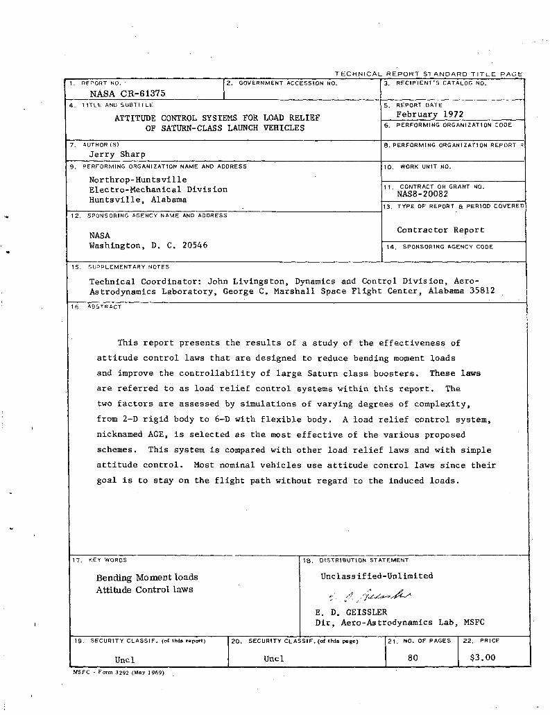
This report presents the results of
attitude control laws that are designed
a study of the effectiveness of
to reduce bending moment loads
and improve the controllability of large Saturn class boosters. These laws
are referred to as load relief control systems within this report. The
two factors are assessed by simulations of varying degrees of complexity,
from 2-D rigid body to 6-D with flexible body. A load relief control system,
nicknamed AGE, is selected as the most effective of the various proposed
schemes. This system is compared with other load relief laws and with simple
attitude control. Most nominal vehicles use attitude control laws since their
goal is to stay on the flight path without regard to the induced loads.
17
19
K.£Y W O R D S
Bending Moment loadsAttitude Control laws
. S E C U R I T Y CLASSIF. (of this report)
Uncl
1S. D I S T R I B U T I O N STATEMENT
Unclassified-Unlimited
-;. J, /ju^-JL*E. D. GEISSLERDir, Aero-Astrodynamics Lab,
20. SECURITY CLASSIF. (of this page)
Uncl
21. NO. OF PAGES
80
MSFC
22. PRICE
$3.00
MSFC - Form 3292 (May 1969)
SUMMARY
This report evaluates the effectiveness of several proposed load relief
control laws and selects a candidate control law that promises to best relieve
bending moment loads while holding dispersions to a minimum.
Saturn class vehicles are capable of lifting very large payloads into
earth orbit. However they are usually limited by bending moment loads to
payloads smaller than their propulsive capability. The principal in-flight
disturbance is wind and wind induces the severest bending moments on the vehicle
other than those caused by mechanical failures.
Since the vehicles considered in this report are aerodynamically unstable
during most or all of their boost stage-, they tend to head away from the wind
with simple attitude control systems, a situation that increases bending
moments and reduces controllability. Therefore the load relief control laws
examined in this report all have one thing in common. They act to turn the
vehicle into the wind.
Simulation of the various vehicles with the proposed control systems
enables the investigator to choose the scheme that best alleviates the flight
problem of the particular booster, whether it is excessive bending moments or
uncontrollability, or both. Using mostly rigid body simulations, a control law
(AGE) was devised that appears to best meet both of these problems. After the
rigid body effects were assessed, the flexible body effects were examined by
simulation programs and stability tools such as closed loop eigenvalue calcu-
lations, root locus, nyquist and Bode plots. The AGE control law appears to
pass all these tests satisfactorily. Flexible body effects have been examined
in full detail on some of the configurations and preliminary filters are
IV OVERALL LOAD RELIEF CONCLUSIONS AND RECOMMENDATIONS 4-1
4.1 CONCLUSIONS 4-14.2 RECOMMENDATIONS 4-1
V REFERENCES AND BIBLIOGRAPHY ...... 5-1
iv
LIST OF ILLUSTRATIONS
Figure Title Page
1-1 VEHICLES EXAMINED IN REPORT 1-2
1-2 DRIFT MINIMUM SYSTEM 1-3
1-3 AGE SYSTEM 1-4
1-4 CONTROL GAIN SCHEDULE FOR THE PROPOSED S-IC AGE SYSTEM 1-5
2-1 EQUATIONS OF MOTION 2-2
2-2 EXAMPLE OF WINDS USED IN INTERMEDIATE-21 STUDY 2-4
3-1 MAXIMUM BENDING MOMENT FOR AC, DM, AND AGE SYSTEMUSING FT ANALYSIS 3-2
3-2 WIND USED IN FIXED TIME STUDY 3-3
3-3 COMPARISON OF BENDING MOMENT OF ATTITUDE AND AGE CONTROLFOR SYNTHETIC AND MEASURED WINDS 3-5
3-4 BENDING MOMENT AS A FUNCTION OF u^ WITH C AS A PARAMETER. . . . 3-7
3-5 BENDING MOMENT AS A FUNCTION OF u^ WITH u^ AS A PARAMETERFOR THE DMWD LAW 3-8
3-6 ENGINE DEFLECTION ANGLE AS A FUNCTION OF u WITH t, ASA PARAMETER . 3-9
3-7 S-IB-AAP GAIN SCHEDULES FOR DM SYSTEM, DMWD SYSTEM,AGE-SYSTEM AND NOMINAL GAIN SCHEDULE i 3-11
3-8 MAXIMUM BENDING MOMENTS FOR VARIOUS CONTROL LAWS FOR 5SYNTHETIC WINDS 3-12
3-9 MAXIMUM BENDING MOMENTS FOR VARIOUS CONTROL LAWS FOR 5MEASURED WINDS ; 3-13
3-10A PITCH WIND SPEED COMPONENT (W ) AT LAUNCH TIME OF AS-504. . . . 3-16X
3-10B YAW WIND SPEED COMPONENT AT LAUNCH TIME OF AS-504 3-16
3-11 RIGID BODY VARIATION OF PEAK a, 0 WITH TIME OF GUST - 95%SYNTHETIC WIND, 141-FOOT PAYLOAD 3-24
3-12 RIGID BODY a, 0 RESPONSES VS PAYLOAD LENGTH - GUST ATMAX Qa - 95% SYNTHETIC WIND 3-24
3-13 ANGLE-OF-ATTACK VS PAYLOAD LENGTH 3-27
3-14 GIMBAL ANGLE VS PAYLOAD LENGTH 3-27
3-15 BENDING MOMENT COMPARISONS - 141-FOOT PAYLOAD 3-28
3-16 AC WITH a-MODAL (141-FOOT) EXCITATION - FULL BOEINGSIMPLIFIED FILTERS 3-30
3-17 AGE WITH a-MODAL EXCITATION SENSOR AT 36.6 M (141-FOOT) .... 3-31
LIST OF TABLES
Table Title Page
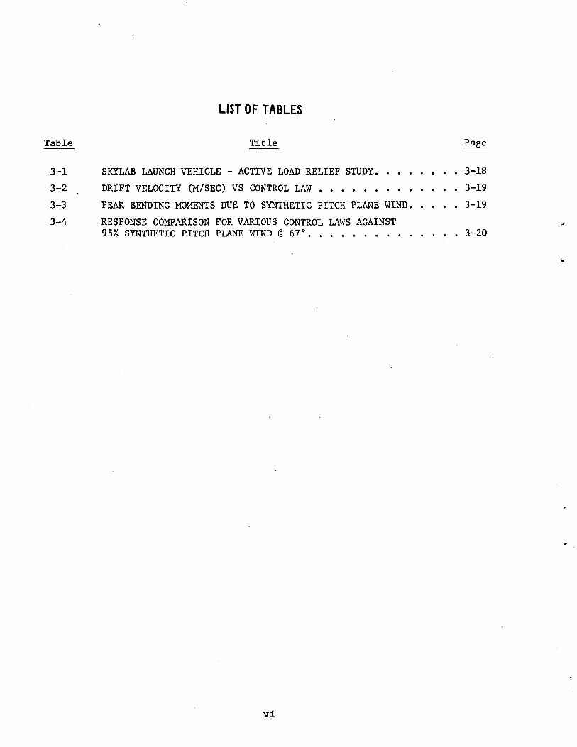
3-1 SKYLAB LAUNCH VEHICLE - ACTIVE LOAD RELIEF STUDY 3-18
3-2 DRIFT VELOCITY (M/SEC) VS CONTROL LAW 3-19
3-3 PEAK BENDING MOMENTS DUE TO SYNTHETIC PITCH PLANE WIND 3-19
3-4 RESPONSE COMPARISON FOR VARIOUS CONTROL LAWS AGAINST95% SYNTHETIC PITCH PLANE WIND @ 67° 3-20
vl
DEFINITION OF SYMBOLS
ENGLISH
Symbol Definition
a attitude feedback gain
a attitude rate feedback gain
AC attitude error plus attitde error feedback or attitude control
AGE attitude rate plus lateral body-axis acceleration and referenceaxis velocity feedback
C aerodynamic moment coefficienta
C aerodynamic force coefficienta
0 \nyC2 R' VXy
D reference diametero
e velocity feedback gain
F total axial thrust
F total axial drag
g_ body accelerometer feedback gain
!„ moment of inertia of movable enginesHi
I moment of inertia of vehicle about y-axis
lc^ length from engine e.g. to engine gimbal point
Kl (FT ~ V /M = *
K Q C /Ma
K3 • R'/M
M mass of vehicle
>L modal mass of i bending mode
vii
DEFINITION OF SYMBOLS (Continued)
ENGLISH
Symbol Definition
fcL mass of movable engines
M . mass of j slosh modesj
MT angle of attack bending moment coefficient
M' engine deflection angle bending moment coefficient
q dynamic pressure
TT q D2
« -R' vectorable thrust
V velocity along trajectory
V wind velocity
x missile body axis (positive forward)
X displacement along missile reference axis (positive forward)
x missile body station of center of gravity
x missile body station of center of pressure
x^ missile body station of engine gimbal
x missile body station of attitude gyro&
X, missile body station of rate gyro,
x x - xcp eg cp
*E Xcg -
XE
y missile body axis
Y displacement along missile reference axis
t~Viy.(x) normalized bending displacement at station (x) of i mode
viii
DEFINITION OF SYMBOLS (Concluded)
ENGLISH
Symbol Definition
y.(x) slope of normalized displacement at station (x) of i mode
z missile body axis
Z displacement along missile reference axis
z acceleration along the z-axis sensed by body mounted accelerometera
Z velocity at station p along the Z-axis
Z lateral reference-axis translationK
GREEK
a rigid body angle of attack
a angle of attack due to windw
6 engine deflection angle
3 engine deflection command
3 engine force command
£ engine quadratic damping
5. damping of i bending mode
n. generalized bending mode coordinate
<)> rigid body yaw attitude error
4> rigid body yaw attitude rate
<f> attitude gyro outputo
<j> rate gyro output
to drift rootD
to natural frequency of engine quadratic
t*V»to natural frequency of i bending mode
to natural frequency of rigid body
ix
Section I
INTRODUCTION
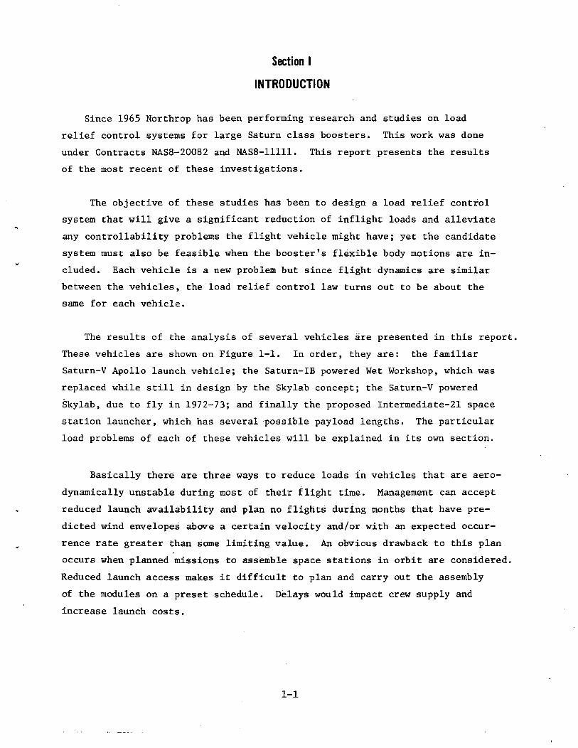
Since 1965 Northrop has been performing research and studies on load
relief control systems for large Saturn class boosters. This work was done
under Contracts NAS8-20082 and NAS8-11111. This report presents the results
of the most recent of these investigations.
The objective of these studies has been to design a load relief control
system that will give a significant reduction of inflight loads and alleviate
any controllability problems the flight vehicle might have; yet the candidate
system must also be feasible when the booster's flexible body motions are in-
cluded. Each vehicle is a new problem but since flight dynamics are similar
between the vehicles, the load relief control law turns out to be about the
same for each vehicle.
The results of the analysis of several vehicles are presented in this report.
These vehicles are shown on Figure 1-1. In order, they are: the familiar
Saturn-V Apollo launch vehicle; the Saturn-IB powered Wet Workshop, which was
replaced while still in design by the Skylab concept; the Saturn-V powered
Skylab, due to fly in 1972-73; and finally the proposed Intermediate-21 space
station launcher, which has several possible payload lengths. The particular
load problems of each of these vehicles will be explained in its own section.
Basically there are three ways to reduce loads in vehicles that are aero-
dynamically unstable during most of their flight time. Management can accept
reduced launch availability and plan no flights during months that have pre-
dicted wind envelopes above a certain velocity and/or with an expected occur-
rence rate greater than some limiting value. An obvious drawback to this plan
occurs when planned missions to assemble space stations in orbit are considered.
Reduced launch access makes it difficult to plan and carry out the assembly
of the modules on a preset schedule. Delays would impact crew supply and
increase launch costs.
1-1
MTEnCOUTC-21 VEHICLES
A
I I,
/ \
11 a
Figure 1-1. VEHICLES EXAMINED IN REPORT
The second load relief procedure is wind biasing. Pitch plane wind biasing
now used on Saturn/Apollo flights and has proved successful in the past. How-
ever, the S-IC has the least severe load problem of any of the other vehicles
under this study and some of the other configurations don't receive enough load
relief from wind biasing to achieve a suitable launch availability. Furthermore,
the wind biasing depends on accurate statistical prediction of the expected wind,
since current launch rules require the biasing program to be programmed several
months before the flight.
The third method, and the technique presented in this report, is active load
relief using a load relief control system. The control system is designed to
turn the booster into the wind to reduce loads. Two different kinds of sensors
can create this effect, accelerometers and angle-of-attack meters. Results have
shown that these two sensors give equivalent rigid body responses (ref. 12).
Allowing the vehicle to turn into the wind reduces the angle-of-attack.
This in turn increases the controllability since the control system is not
trying to hold the vehicle to some preset, open loop programmed, attitude angle.
Since the bending moment is calculated from equation (1) it too will be reduced
if the load relief control system does its work well.
1-2
nBM(a, 3, n, , X) = M'(X) * a + M'(X) * @ + I M-'- (X) * n
Ct P j = = i ' l j 1
The M' are the bending moment partials with respect to angle-of-attack (a),
gimbal angle (g), and flexible body mode acceleration (n.).
(1)
The only terms not obviously reduced by the load relief control law are
those that depend on n.. The text, of the report attempts to assess the impact
of these variables as well as angle-of-attack and gimbal angle. In general
the results show that the effect of the bending vibrations is not enough to
drastically change the bending moment comparisons, and of course the vibrations
don't appreciably change the gimbal angle requirements.
For the most part, only two control laws are used. The first, the "drift
minimum" law, was originally designed to reduce drift on the Saturn I-B, a by-
product being reduced loads. This system feedback paths are shown in Figure 1-2,
Figure 1-2. DRIFT MINIMUM SYSTEM
1-3
A three-gain system like the drift minimum system allows the analyst to
specify the system closed loop natural frequency (u> ), the damping ratio (c),
and the drift root*(co ). It is shown in this report that allowing 01 to get
large increases the load reduction. This may cause some confusion in the
nomenclature since the original drift minimum system was so named because u>
was forced to zero. Perhaps a better name would be free drift or AAG (for an,
a.., g«) but drift minimum is the original name.
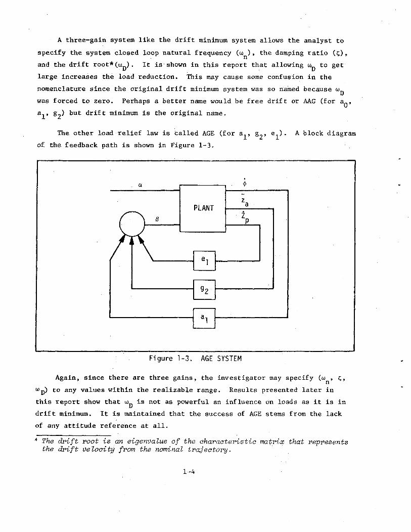
The other load relief law is called AGE (for a.., g?, e ). A block diagram
of the feedback path is shown in Figure 1-3.
Figure 1-3. AGE SYSTEM
Again, since there are three gains, the investigator may specify (w , c;,
Wp) to any values within the realizable range. Results presented later in
this report show that ui is not as powerful an influence on loads as it is in
drift minimum. It is maintained that the success of AGE stems from the lack
of any attitude reference at all.
The drift root is an eigenvalue of the characteristic matrix that representsthe drift velocity from the nominal trajectory.
1-4
Regardless of the load relief control law, it is only used during the high
q region of flight. The actual times depend on the vehicle and its trajectory.
Load relief is not needed during the remainder of flight and there are draw-
backs to load relief during lift-off or near the end of flight. During lift-
off, a load relief control law will have tower clearance problems. Near the end
of first stage flight the Saturn I-C has an attitude freeze in order to avoid
interfering with the second stage iterative guidance and to remove transients
before separation. Any load relief system would be unsuitable for this attitude
freeze.
A typical gain schedule, as used in the report, is shown in Figure 1-4.
The gains are ramped in and out to avoid large artificial transients in the
control system.
1.2-i n -i1 . U
[a 1 fi-ao]'6
0-
1 2n
Fa 1 6-L ^J *4-
0-
.03-,
9? n -
-.03
.0003n
Q-I n -
- nnrn —
C
\\ /\\ s
I I 1 1
/L l 1 1\ /
) 55 60 lOOi 105
Figure 1-4. CONTROL GAIN SCHEDULE FOR THE PROPOSED S-IC AGE SYSTEM
1-5
Section II
MATH MODELS
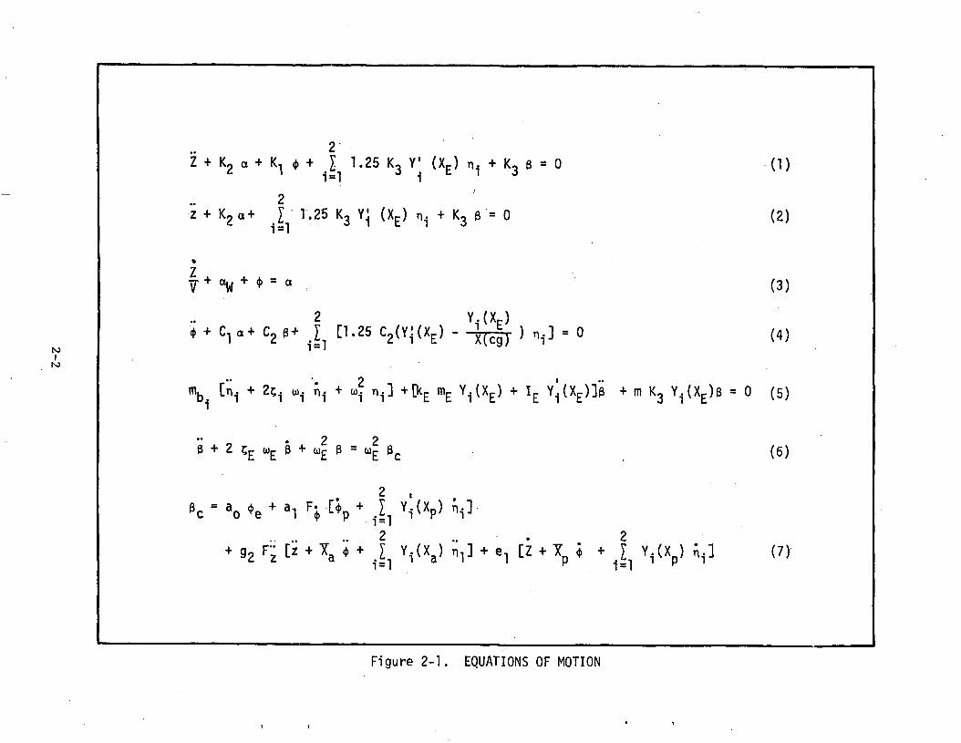
2.) EQUATIONS OF MOTION
Most of the work in this study was done using a perturbation program
having two degrees of rigid body freedom and two bending modes. These equa-
tions are assembled in Figure 2-1 and programmed on an EAI 690 hybrid computer.
This simple model was used for a good percentage of the work, but two other
simulation tools were used when a more detailed examination of some of the
phenomena was required. One of these simulations included a full six-degree-
of-freedom and the other had five-degrees-of-freedom (no roll) with flexible
body effects (a hybrid program on the EAI 8900).
The principal investigative tool is the EAI 690 2-D program. It has the
capability for second-order servo, nonlinear aerodynamics and filters along
with the two degrees of rigid body freedom and two bending modes.
The EAI 8900 system is a hybrid system with two main components. The EAI
8800 analog computer was hooked in a dual patchboard mode with each patchboard
having 60 integrators, 60 summers, 80 inverters (18 of which function as
multipliers), and 220 servo-set potentiometers. This system was interfaced
with an 8400 digital computer with 32 parallel D/A conversion channels.
The EAI 690 also has two main components. The EAI 680 analog computer is
equipped with 30 integrators, 24 summers, 90 inverters, various function genera-
tors and comparators and 120 servo-set potentiometers. It is coupled by 24
A/D trunks and 12 D/A trunks to the EAI 640 digital computer.
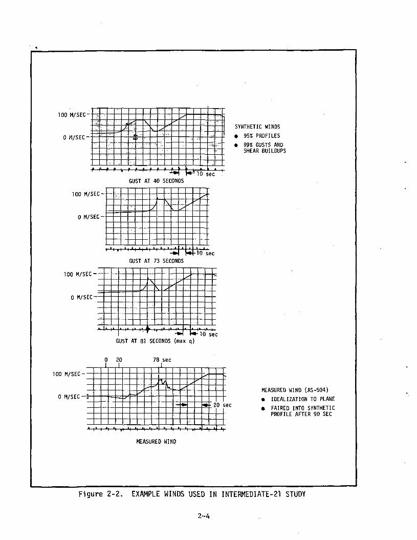
2.2 WIND
The greatest cause of loads during the boost phase of flight is wind. For
the worst case wind, this study uses an artifical wind profile based on references
15 and 16. This profile represents a March wind with magnitude equal to a greater
than 95 percent of previously measured March winds and shear buildup and gust
greater than an equal in severity to 99 percent of measured March values. This
2-1
r—
CM
C
O
. * ;}•
in
to
!"•>•
OIIcaS
~**
•
1
I
Ul
-i-x
• er
XC
O**S
*r~~
e
^+
-
CMC —
111•r—
: ca
4-
r~i
O
ui
• -e-X
II —
' . Q
.O
- -i-
p<
^™
• i»
—
11 -i-
+er
uicaC
O
*~S
£
O
*->Ul
+
11
X^~*
•r- ca
•«
-cr
>-C
O*-
i
Ul
X
4-
—.
I-H
. M
"^
^^J
C7)
^->
, C
O0
Ul
• —
x
+X
^—
•*•t- 1 —
1 1 —
1
• c
: er
Ul
ui
a.
<o
•r
-
X
Ul
XX
CO
U
l >-
*^s X
•1—
.
*f—
•!—
:
+
oC
M
i — i
ca
?—
t—
O
t- C
MC
111
C
MC
^JII
inC
T
CM
U
l T-
t-CM
-i-
in
3•
>-
c\^~
CO
r-
1—
i
1_C
MC
-<J II•r-
inCM
C
Mt-
+
. •
-e- "~
•»t—
a
q
w—
C
M C —
J ||
i
T-
II
J
CM
-r-
+
+3
IIcx
: -e-
J
+
oa
.-e-
1 i
fOf—
-r-
CM
U
l Ip
X-J
ii « cr
3 .-e
-<r"
' i-
4-
U.
+3~
r-
: fs
|3.
«ca
to
i — i
•r"CM
u>
U
l 4-
: : N0
CM
3
U.
+
-e-
+
H(U
4-
Ul
-e-
CM
8
3
+a
^
• "
0C
T
CM
C
M
S
+
+
-r H
.—
: C
T
CM
«a
4-)
1 1
+
II•
*^~
n
I CQ
O:M
: N
»tx
i|^»
:.-e-
£
ca
2^o1—
*
o^u,
oco0£_ir
cy#.
CMS-
_.
1 1
2-2
profile is shown in Figure 2-2 with a gust time at 73 seconds for an Intennediate-21
flight. Other flight times are used for the Intermediate-21 and other vehicles but
the analysis is concentrated in the time near the region of maximum q or maximum
q*a product. In general, this time is different for each vehicle.
This study also uses an example of a severe measured wind. This wind was
measured on the AS-504 flight and is the worst wind a Saturn class vehicle has
yet to actually experience. The wind has a changing azimuth to go with its
varying magnitude so it cannot be shown on a single chart but it is used in the
five-degree hybrid program. However, an idealization of this wind to the plane is
shown in Figure 2-2. This wind is used in the 2-D hybrid program. Other, less
severe, measured winds are also used in the 2-D studies. All these winds were
picked as representative of the more severe winds a vehicle is likely to
encounter in flight.
2-3
TOO M/SEC-
0 M/SEC-
- •~:
•l'- -
fs
;
:
5S,
4•C
• .-.
3
Xs
..-
s
•-
s/
-•~
•.-.~-_
K^IO sec 'GUST AT 40 SECONDS
100 M/SEC-
0 M/SEC-
10 secGUST AT 73 SECONDS
100 M/SEC--
0 M/SEC—
GUST AT 81 SECONDS (max q)10 sec
100 M/SEC--
0 M/SEC -i
0 20I
78 sec
SYNTHETIC WINDS
• 95% PROFILES
• 99% GUSTS ANDSHEAR BUILDUPS
20 sec
MEASURED MIND
MEASURED WIND (AS-504)
• IDEALIZATION TO PLANE
* FAIRED INTO SYNTHETICPROFILE AFTER 90 SEC
Figure 2-2. EXAMPLE WINDS USED IN INTERMEDIATE-21 STUDY
2-4
Section III
RESULTS
3.1 SATURN V/APOLLO
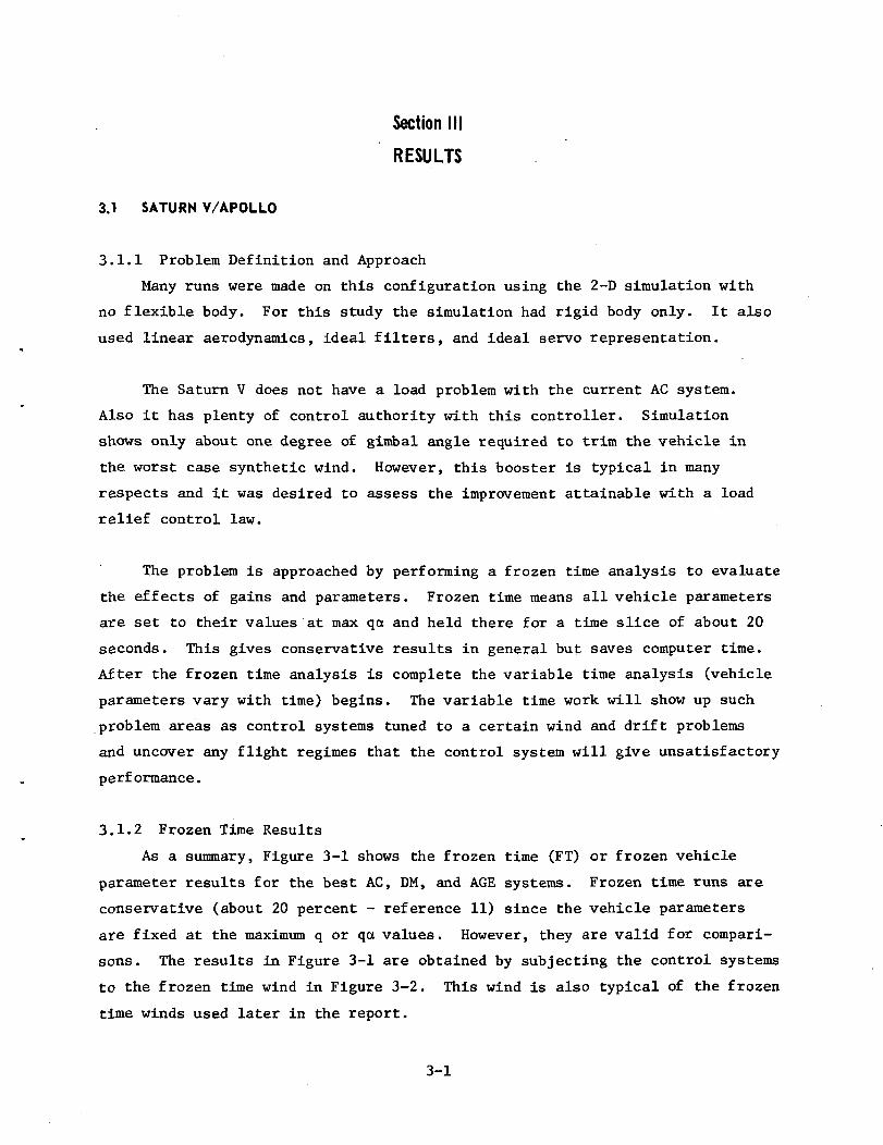
3.1.1 Problem Definition and Approach
Many runs were made on this configuration using the 2-D simulation with
no flexible body. For this study the simulation had rigid body only. It also
used linear aerodynamics, ideal filters, and ideal servo representation.
The Saturn V does not have a load problem with the current AC system.
Also it has plenty of control authority with this controller. Simulation
shows only about one degree of gimbal angle required to trim the vehicle in
the worst case synthetic wind. However, this booster is typical in many
respects and it was desired to assess the improvement attainable with a load
relief control law.
The problem is approached by performing a frozen time analysis to evaluate
the effects of gains and parameters. Frozen time means all vehicle parameters
are set to their values at max qa and held there for a time slice of about 20
seconds. This gives conservative results in general but saves computer time.
After the frozen time analysis is complete the variable time analysis (vehicle
parameters vary with time) begins. The variable time work will show up such
problem areas as control systems tuned to a certain wind and drift problems
and uncover any flight regimes that the control system will give unsatisfactory
performance.
3.1.2 Frozen Time Results
As a summary, Figure 3-1 shows the frozen time (FT) or frozen vehicle
parameter results for the best AC, DM, and AGE systems. Frozen time runs are
conservative (about 20 percent - reference 11) since the vehicle parameters
are fixed at the maximum q or qa values. However, they are valid for compari-
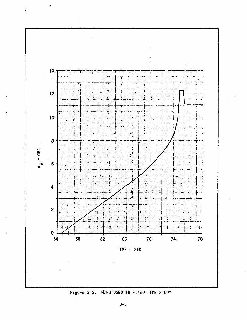
sons. The results in Figure 3-1 are obtained by subjecting the control systems
to the frozen time wind in Figure 3-2. This wind is also typical of the frozen
time winds used later in the report.
3-1
2 9*. • y —
2.8-
2.7-
coC\J
•py0*""* O C1 — C .01—oo
1
rp ?
o * t ! j
X
E
LU
O
CD
S 2 3oLU03
2 2^ • b
2.1 -
2.0-
01>
"N-
"N =
0.5
0.7
,
UN = 1.1
-UN == 1.1
u - n 7
n «;WN
0) =N
1
0.7
0.5
— -^
— 1
•" u.
1 —
\
V
,
— —
X
1
1
— -
'
l\
— „,^^^ • •B
- ^
."'
— -,
> •"
\N
I BI ^ II
^
AC
TTITUDEONTROL (AC)
SYSTEM
DRIFTMINIMUM (DM)
u f*\/f*Tr™RjSYSTEMWn = 0
AGF, SYSTEM
tOn> = 0
0 .1 .2 .3 .4 .5 .6 .7 .8 .9 1.0
c -*•
Figure 3-1. MAXIMUM BENDING MOMENT FOR AC, DM, AND AGE SYSTEM USING FT ANALYSIS
3-2
o><u•o
78
Figure 3-2. WIND USED IN FIXED TIME STUDY
3-3
Results given in reference 7 show that AGE gives slightly better bending
moments (5 percent) with a non-zero drift root but the improvement must be
balanced against larger transients at ramp-out and increased drifts and drift
rates.
A comparison of the results reveals that the best AGE gain set (a),, = 0)
reduces bending moments by about 23 percent compared to AC while DM reduces
loads only about 4.5 percent. On the basis of this study, this AGE system
is chosen as the load relief law for the next part of the study.
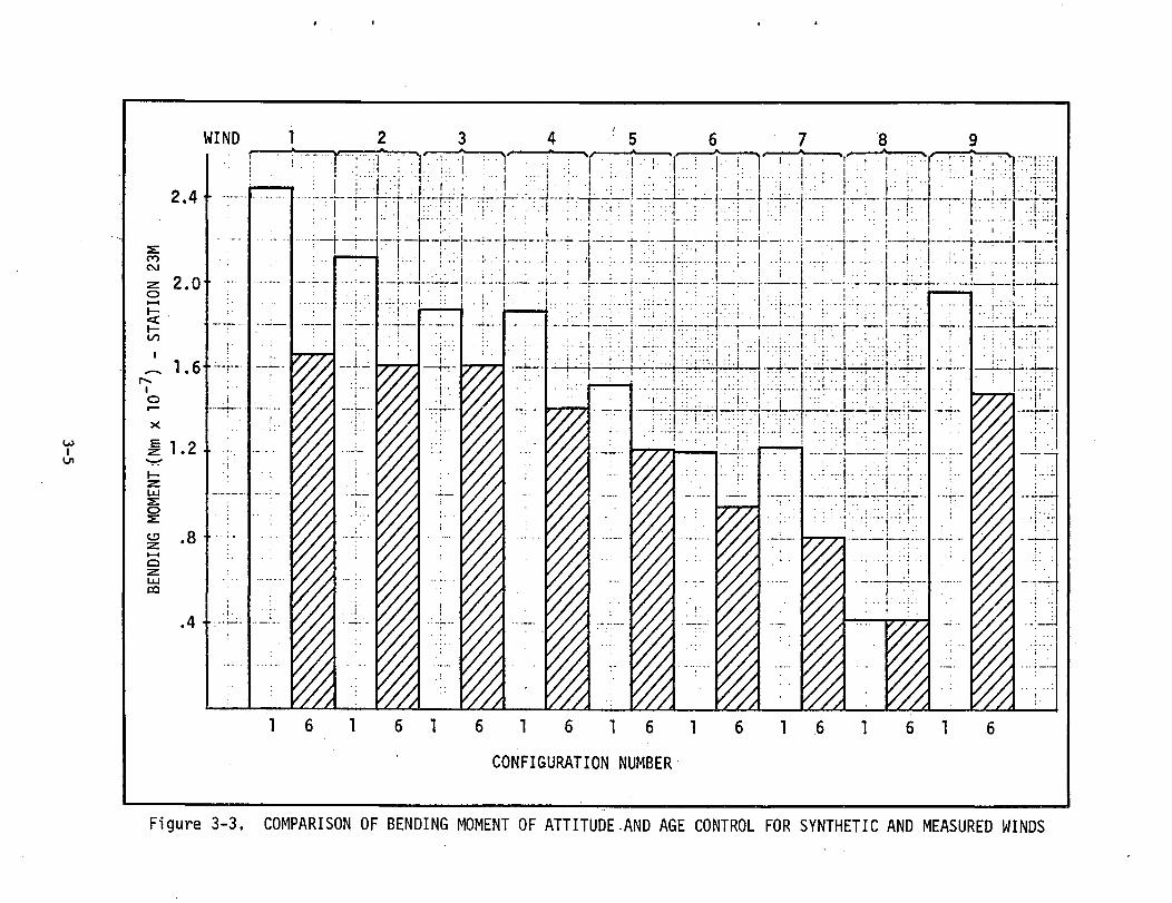
3.1.3 Variable Time Results
Nine different winds are used for this part of the study. They include
three 95-percentile profiles with 99-percentile shears and gusts occurring at
different flight times. One of the winds is a reverse shear with 95-percentile
profile and 99-percentile shear breakoff. Five measured winds make up the
remainder of the nine winds used in the study. These winds are given in
reference 7.
The results of the wind study are in Figure 3-3. Configuration 1 is the
reference AC system and configuration 6 is the AGE system chosen for best all
around response characteristics and best reduction of bending moments. It can
be seen that the bending moment reduction from AC to AGE varies about from 17
to 33 percent, with the exception of wind 8 which is a low magnitude, early
peaking, measured wind. Wind 8 does not cause very high bending moments in
any case.
3.1.4 Summary
In summary, an AGE control law has been shown effective in reducing in
flight bending moments to a significant degree. Since controllability is not a
problem on the S-IC, the increase in gimbal margin is not shown. However, the
interested reader can find the comparison between gimbal angle requirements
for AGE and AC in reference 7. It should be pointed out that no flexible body
equations are used in this vehicle study.
3-4
..i _•__•.
eo<
:| -
"T
"
vo10-n:: :]::i j.
co<
CM
'
,/!••:! ;
l
i
CM
O•
CM
VO
CSJ
W£2
NO
I1V1S -
(Z_OL
009N
IQN
39
oLU
OtL
oI—H
I—LU
vovovo
orLlJ
CO
s<cLUQ
oovovovo
LU
OCD
I-H
Q•z^LUC
D
OI/OoocoICO(U3
3-5
3.2 SATURN IB WET WORKSHOP
3.2.1 Problem Definition and Approach
This study is done almost entirely on the 2-D simulation, which has rigid
body, linear aerodynamics and no filters. The approach is similar to the S-IC
study. First a frozen time analysis is made using the March worst case
synthetic wind shown in Figure 3-2. Vehicle parameters are frozen at max qa
(67.5 seconds). After the frozen time analysis points up the influence of the
various parameters on bending moment, angle-of-attack, and gimbal angle, a
variable time analysis is performed to further tune the gains and examine the
secondary effects of the chosen control systems.
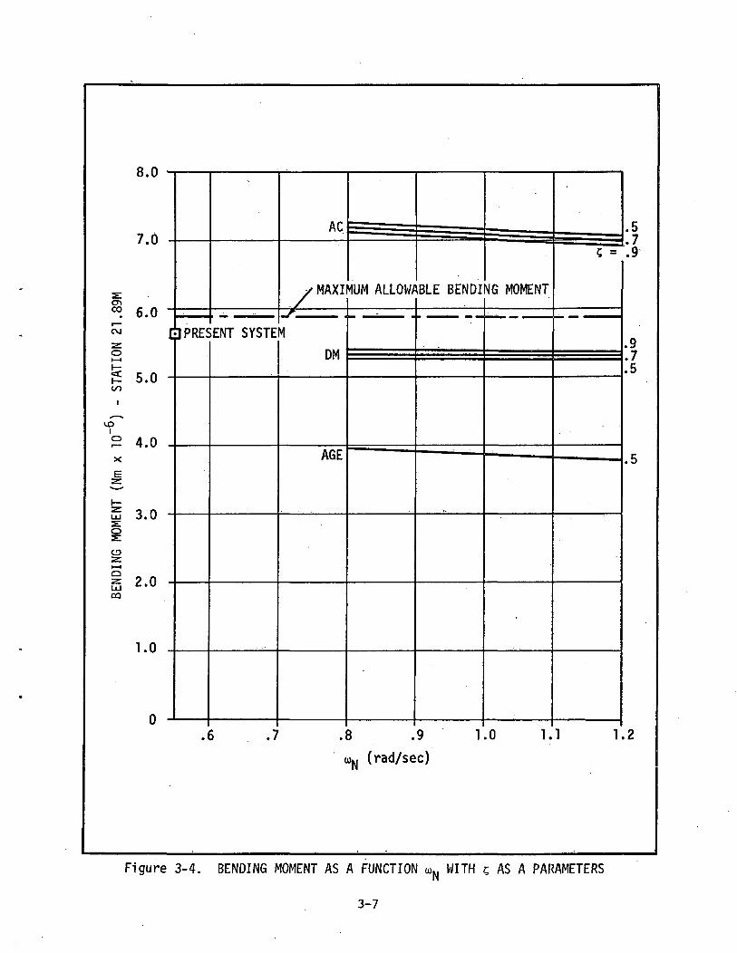
3.2.2 Frozen Time Results
The frozen time analysis is summarized in Figure 3-4. Here it can be seen
that bending moment is, in general, lowest for the AGE control system, higher
for the drift minimum (DM) system, and highest for the AC reference system.
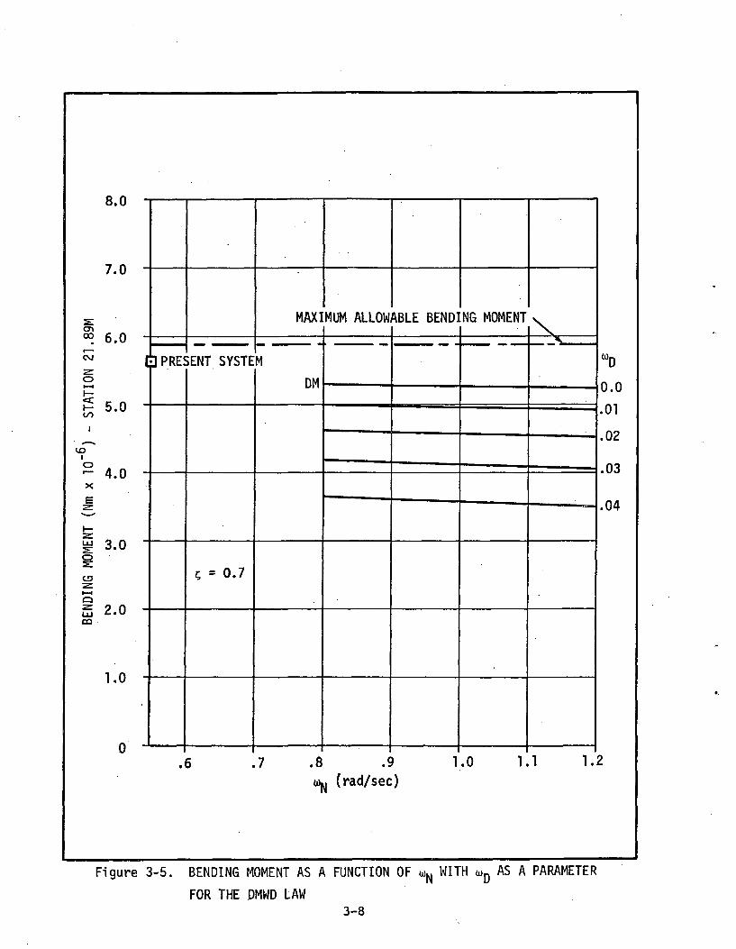
Figure 3-5 shows that the drift minimum control law with non-zero drift root
(DMWD) falls between the drift minimum law and the AGE law, approaching the
latter for increasing magnitudes of u , the drift root. However, the AGE law
used to give the results in Figure 3-4 has w set to zero, and some reduction
in peak bending moment can be gained by letting this root in the AGE law
become larger.
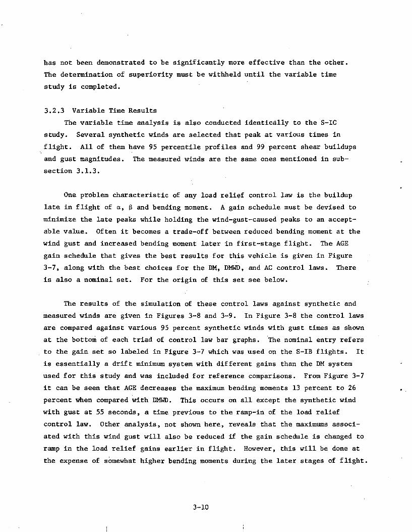
On this configuration, just as on the S-IC booster, controllability is not
a major problem. However, the engine gimbal limits are approached more closely
on the S-IB than on the S-IC. To gain some idea of the controllability margin
on the S-IB, consider Figure 3-6 which gives the gimbal limits and the maximum
gimbal angles for AGE, DM, and AC control laws as a function of w and 5. The
gimbal limits are not exceeded by any control law, even though the study is
done in frozen time which gives conservative results.
Summarizing the frozen time results, we can say that both the DMWD and
AGE control laws yield significant decreases in peak bending moments but one
3-6
8.0
7.0 -
°° 6.0DPRESENT SYSTEM
5.0I/O
2 4.0X
3.0
CD
i 2.(UJ *•"CO
1.0
y MAXIMUM ALLOWABLE BENDING MOMENT
.6 .7
DM
AGE
.8 .9
o»N (rad/sec)
1.0 1.1
.9
.7
.5
.5
1.2
Figure 3-4. BENDING MOMENT AS A FUNCTION u>N WITH 5 AS A PARAMETERS
3-7
8.0 -
7.0 -
s:CT>rv-j c f\ —~ 6.0
^^ t1oi— i
2 c nf— o.Uoo
vo0- 4.0 -X
E
F o « -^ 3.0
CJD
i— «ag 2.0 -ca
1.0 -
] PRE<>ENT SYSTE
? = 0.7
.6
MAXI
M
DM
7 .8
1
MUM ALLOW
•————_
ABLE BEND!
~~—
.9 1^ (rad/sec)
NG MOMENT
- — — —
>^
-
.0 1.1 1.
WD
0.0
.01
.02
.04
2
Figure 3-5. BENDING MOMENT AS A FUNCTION OF <ON WITH UD AS A PARAMETER
FOR THE DMWD LAW3-8
GIMBAL LIMIT
8.0
7.0
6.0
5.0
<u-o
oa
3.0
2.0
1.0
PRESENT SYSTEM
DM
AGE
.6 .7
\
.7
.8 .9 1.0 1.1 1.2U (rad/sec)
Figure 3-6. ENGINE DEFLECTION ANGLE AS A FUNCTION OF o>N WITH 5 AS A PARAMETER
3-9
has not been demonstrated to be significantly more effective than the other.
The determination of superiority must be withheld until the variable time
study is completed.
3.2.3 Variable Time Results
The variable time analysis is also conducted identically to the S-IC
study. Several synthetic winds are selected that peak at various times in
flight. All of them have 95 percentile profiles and 99 percent shear buildups
and gust magnitudes. The measured winds are the same ones mentioned in sub-
section 3.1.3.
One problem characteristic of any load relief control law is the buildup
late in flight of a, g and bending moment. A gain schedule must be devised to
minimize the late peaks while holding the wind-gust-caused peaks to an accept-
able value. Often it becomes a trade-off between reduced bending moment at the
wind gust and increased bending moment later in first-stage flight. The AGE
gain schedule that gives the best results for this vehicle is given in Figure
3-7, along with the best choices for the DM, DMWD, and AC control laws. There
is also a nominal set. For the origin of this set see below.
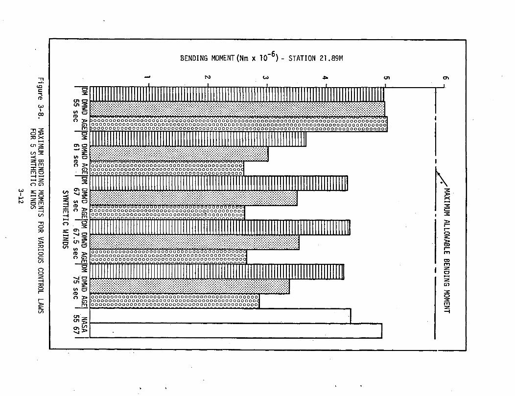
The results of the simulation of these control laws against synthetic and
measured winds are given in Figures 3-8 and 3-9. In Figure 3-8 the control laws
are compared against various 95 percent synthetic winds with gust times as shown
at the bottom of each triad of control law bar graphs. The nominal entry refers
to the gain set so labeled in Figure 3-7 which was used on the S-IB flights. It
is essentially a drift minimum system with different gains than the DM system
used for this study and was included for reference comparisons. From Figure 3-7
it can be seen that AGE decreases the maximum bending moments 13 percent to 26
percent when compared with DMWD. This occurs on all except the synthetic wind
with gust at 55 seconds, a time previous to the ramp-in of the load relief
control law. Other analysis, not shown here, reveals that the maximums associ-
ated with this wind gust will also be reduced if the gain schedule is changed to
ramp in the load relief gains earlier in flight. However, this will be done at
the expense of somewhat higher bending moments during the later stages of flight.
3-10
I I
ao
o
' c\j
1010
CM
O>
(oes/peu/peu)
CO
cooUJ
LU
h- _l
co ro
>- o
CO LU
s o
Q CO
o •-«
u_ <CD
COLU _1
—I <C
13 ^
O I-H
LU s:
DC O
o -z.
co«=C CO
<c >-
i co
co i
I—I
LU
I CD
CO <C
co<u3CD
3-11
6 -
5 -
s—
4 nC
M
0I-H
1—oo
vo'o
3-
Xez:
1—til2:o
2
-•ZLI-H
oLU
DO
1 •]
.^MAXIM
UM
ALLOWABLE
BEND
ING
MOMENT
DM CE )MW
D)5
S6
>ooooooooooooooooooooooooooooooooooooooocoooooooooooooooooooooooooooooooooooooooo) O O O O O O O O O O O O O O O O O O O O O O O O O O O O O O O O O O O O O O O (I O 3> 3 O O O O O O O O O O O O O O O O O O O O O O O O O O O O O O O O O C
f f ) O O O O O O O O O O O O O O O O O O O O O O O O O O O O O O O O O Om jooooooooooooooooooooooooooooooooocDM
C6 MUD
1 se u
O I » r o o O O O O O O O O O O O O O O O O O O O O O O O O O O O O O O O Offjpooooooooooooooooooooooooooooooooocrn|ooooooooooooooooooooooooooooooooooDM C6
•;•:•:•;•;
IMWD
7 s<SYNT 11110
°§
'2
o°c
o°o
cg
og
co
°oc
2o
°c2
o°c
o°o
c2
o2
c°S
§r
go
°c
AGE
iCHET1
DM C6/C W
)MWD
'.5 £
INDS y
oooooooooooooooooooooooooooooooooo H; .. 1DOOOOOOOOOOOOOOOOOOOOOOOOOOOOOOOOOC ~s y \oooooooooooooooooooooooooooooooooo ^ HJ I
pBBBM
MM
q
DM C1 MWD5 se
[ooooooooobooooooooIOOOOOOOOQ
oooooooooooooooooooooooooooooooooolLU 1oooooooooooooooooooooooooooooooooodCJ 1ooooooooooooooooooooooooooooooooool "=C O 1
JOOOOOOOOOOOOOoooooooooooooci n nn firan.qn cv? fv?n
DM DMWD
AGE9
NA55
SA67MEASURED WINDS
Figure 3-9. MAXIMUM BENDING MOMENTS
FOR VARIOUS CONTROL LAWSFOR 5 MEASURED WINDS
3-13
The maximum bending moments for the named control laws against five mea-
sured winds are given in Figure 3-9. It can be seen from this figure that
measured winds produce less severe bending moments than the synthetic winds
used.
Bending moments are approximately the same except AGE is slightly lower
when differences are visible. From this result and other similar results it
is concluded that AGE is relatively less effective when the absolute wind magni-
tudes are lower and when real winds with repeated gusts and shears are considered.
However AGE is never less effective than the other control laws in any wind.
3.2.4 Summary
Summarizing the results for the S-IB Wet Workshop, AGE was again shown to
be the most effective load relief law. Bending moment reductions are no less
than 13 percent when compared with DMWD against synthetic winds. The control-
lability margin is much improved when compared to the current flight controller,
but DMWD gives similar results. Against the measured winds AGE again has the
edge, but the improvement over DMWD is slight. However, any of the proposed
systems, including the current NASA system, will handle these winds.
3.3 SKYLAB LAUNCH VEHICLE
3.3.1 Problem Definition and Approach
This vehicle, designed to launch a small space station in 1972-73, is
the first to show unacceptable bending moments in the AC mode when launched
against a 95 percent March synthetic wind. Even wind biasing will not give
acceptable launch margins for the most severe synthetic winds. Therefore,
load relief control becomes necessary on this booster stack if one is to avoid
reduced launch availability.
The method of attack on this vehicle differs from the previous two in c
several ways.
• The simulation used is a five-degree-of-freedom (no roll) flexiblebody simulation of the Skylab Launch Vehicle.
• Load relief laws used are AGE and load minimum. The latter controlsystem uses the same feedback paths as AGE but does not feedback thereference velocity (associated with e.. gain) .
3-14
• Flexible body effects are included for the first time to determine theinfluence of flexible body modes on the load relief capabilities ofeach control law under investigation.
• There are two stages in the analysis, called "sensed" and "unsensed".In the unsensed analysis flexible body motion is present in the vehiclebut ideal filters are assumed, i.e., no bending motion is fed backthrough the control system. In the "sensed" analysis flexible bodymotion is felt at the sensors and the sensor signals are fed backthrough simple compensating filters.
As in the previous analyses the load relief control laws are used only
during the period of high aerodynamic loads. As in the past this is accomplished
by flying the vehicle under AC during the early flight phase then ramping the
attitude gain to zero while ramping in the desired load relief gains.
Ramp durations of five seconds are used, ramp-in beginning at 45 seconds
and ramp-out at 95 seconds. These times were determined by experimentation
with the synthetic wind profile and the measured wind described below.
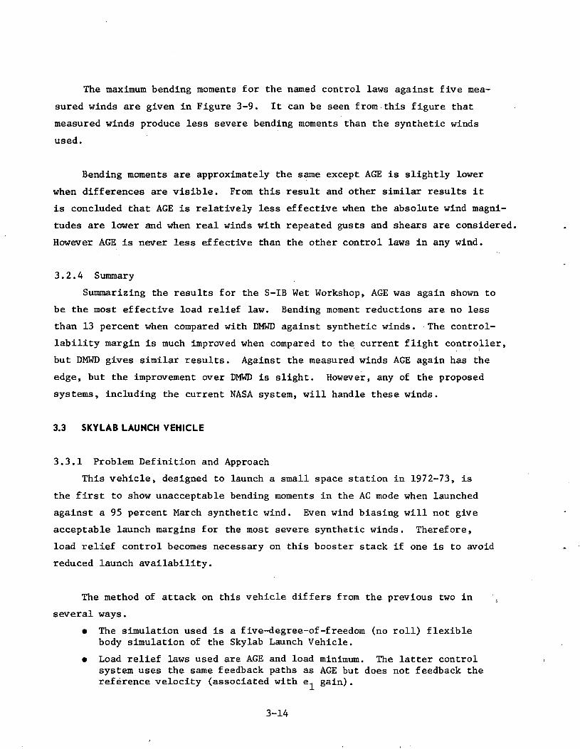
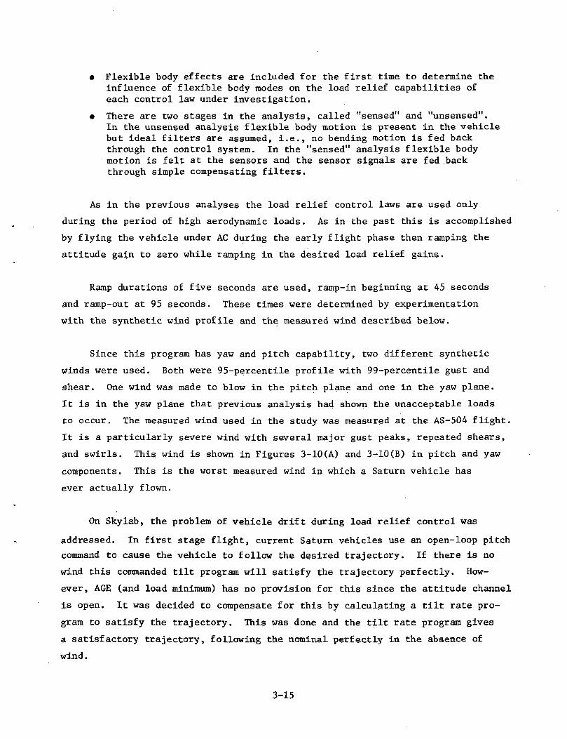
Since this program has yaw and pitch capability, two different synthetic
winds were used. Both were 95-percentile profile with 99-percentile gust and
shear. One wind was made to blow in the pitch plane and one in the yaw plane.
It is in the yaw plane that previous analysis had shown the unacceptable loads
to occur. The measured wind used in the study was measured at the AS-504 flight.
It is a particularly severe wind with several major gust peaks, repeated shears,
and swirls. This wind is shown in Figures 3-10(A) and 3-10(B) in pitch and yaw
components. This is the worst measured wind in which a Saturn vehicle has
ever actually flown.
On Skylab, the problem of vehicle drift during load relief control was
addressed. In first stage flight, current Saturn vehicles use an open-loop pitch
command to cause the vehicle to follow the desired trajectory. If there is no
wind this commanded tilt program will satisfy the trajectory perfectly. How-
ever, AGE (and load minimum) has no provision for this since the attitude channel
is open. It was decided to compensate for this by calculating a tilt rate pro-
gram to satisfy the trajectory. This was done and the tilt rate program gives
a satisfactory trajectory, following the nominal perfectly in the absence of
wind.
3-15
25
WIND PROFILE USED TO DESIGN AS-504WIND BIASED OPERATIONAL TRAJECTORY
0 20 40
W I N D SPEED, m/s
Figure 3-10A. PITCH WIND SPEED COMPONENT (W ) AT LAUNCH TIME OF AS-504/v
40
30
20
IS
10
-60 -40 -20
WINDFROM-UfT
20 40 60
WIND SPEED, m/s
Figure 3-1 OB. YAW WIND SPEED COMPONENT AT LAUNCH TIME OF AS-504
3-16
3.3.2 Results of Unsensed Analysis
Most of the control comparisons are performed using unsensed flexible body
modes. Bending moments are calculated at station 26.0 meters, which is toward
the top of the first stage. This point is chosen since the maximum bending
moment due to engine gimbal angle occurs here. The maximum bending moment due
to angle-of-attack occurs at a station slightly forward of this, but the maxi-
mum total bending moment magnitude should be in this vicinity. Bending moments
include the flexible body contributions in both unsensed and sensed flexible
body studies.
Table 3-1 summarizes the results of the unsensed flexible body analysis
for the Skylab. It can be seen that maximum bending moments are reduced 17
percent or more with AGE and 26 percent or more with load minimum. As in the
past the measured wind is the most troublesome to load relief control laws.
It should be noted that the flexible body bending moment contributions do not
degrade the AGE load reduction capability significantly. The highest bending
moments are seen in the crosswind case due to the increased cross sectional
area exposed to the wind from the side direction. As usual the AGE control
law is most effective on the highest loads.
In the AGE row several entries have two values. The first is the value coin-
cident with the wind gust. The second value is that coming during the post gust
buildup. As mentioned previously, this is a characteristic of AGE. In all cases
bending moments are the maximum bending moments observed at any time in flight.
The load minimum control law is consistently the best performer of the
three, but at the time of compilation of this table no results for load minimum
had been obtained past around 90 seconds into flight. It was known that load
minimum control allowed sizable trajectory and attitude divergence and the drift
velocity exceeded the maximum amplifier scale. Later in the analysis, this prob-
lem was solved and it was found that the terminal drift velocity was considerably
higher than AC or AGE (Table 3-2) and the attitude divergence at the end of the
load minimum flight phase caused a large transient in the control system and
hence a large bending moment at that time (Table 3-3). However information on
the magnitude of the bending moments relative to the bending moment limits is
lacking; therefore no statement can be made on the severity of these transient
induced loads.
3-17
a:Q<coLU
O
I
CJ
zCO
coa>
OH- 1
3C,3.0in(**O§g•z.
•**.iniaz1— 1
totooC£OZ</>tna, ,2
1
I—
CD>— • Z
UJ O IO
CO SI CM
,_a>h- <U
CQ T3•O>
1
CDZ H—
»— i Z
a uj
UJ CD IO
CQ S: CM
— .
1— <U
CQ -a~xO)
1— <U
8 T3
IS« Z
O UJ
^»* y*
UJ O U3
CQ s: CM
CQ T3^^
-•ent— <ua
TS_,
OQi
1—
8
Ei
O IOo
CO
">(
PO•CMini-.
U3O"xOo'f
in z
•*in•rf
r
*ao"xo• E5 z
CO
CO
oCS~
Oa:1—1UJQ a»
Is*
^3 •
*
—•— n
nt—1— 0 t—
0C3CO
CM•
CMOCO
OCO
CMm
*fO,
r~~
t—
O•
5:VO
ro0oO\-a o»
en*"^
• »
— >-. it ni—1—
Oi—
t iQ itl
oCMCM
^«
•~0•C3
C5CM
0CM0^0^10
rCM
CO•s.K- «Sa^o
otnCMCM
CM*^in•*~0o•*•oCM
O•
CM
Ocn*in.«-
o•
VO
10r—*1010CO
CM
r— *—
CM CM »—
CM
tO
1 UJ UJ
t_> CO CO
o<sCO
1-1
1ea
tois0}
§
3-1
8
Table 3-2. DRIFT VELOCITY (M/SEC) VS CONTROL LAW
CONTROL LAW
AC
AGE
Load Minimum
TERMINAL DRIFT VELOCITY
50.0
-17.0
-100.0
Table 3-3. PEAK BENDING MOMENTS DUE TO SYNTHETIC PITCH PLANE WIND
CONTROL LAW BENDING MOMENT (STA 26m)AT WIND GUST (n-m x 10-°)
BENDING MOMENT (STA 26m)DURING LATE FLIGHT (n-m x 10"6)
ACAGE
Load Minimum
41.016.014.0
No buildup or transient13.023.0
This late flight, ramp-in transient is characteristic of a load minimum
control law and there appears to be no action that will reduce the ramp-in
ping without compromising the load relief at the wind gust. Furthermore, the
terminal drift velocity magnitude is significantly larger than the AC or AGE
values and it is believed probable this would impact performance of the booster.
For these reasons load minimum is dropped from further consideration in this
study.
3.3.3 Results of Sensed Analysis
For the sensed part of the analysis AGE is the only load relief control
law used. Table 3-4 compares various responses against the synthetic pitch
wind. The bottom entry is the row that gives the AGE control law with vibra-
tions sensed and using filters that stabilize the two body modes. The filters
cause some degradation in the responses as can be seen. However the degrada-
tion is considered acceptable and indeed the Intermediate-21 work in subsection
3.4 indicates that AC is more sensitive to filters than AGE. Filtered responses
with AC control laws increase by a larger percentage than filtered AGE responses,
3-19
cocoO <
X3
oca>
cora Q
o z
:
o _
iu. a
..
o o
00 I—I—
I I— I
a: Q-
«cex os: I-Ho
i—O
Ul
co zz: >
-O
CO
a.co s«U
l LO
oz. en
cocusre
Of.
Ul
\- z:
«m
^J
"o"
H-
I- o><=>~
u- t/> z: o<S e
o
^^
fc-l,-" O
)
J
a;
o*^™
. !---<
t^^ .
^zS
DC E
o
Q
<S
i CJ
^
>-
£i e
=
^" i
^oaz
e,
1—
OQ
73
C
D
CL
2*3<s>
0 ^
a. 2
»
•"^
~^^D
-g®
cOi
1 —o0
o•
0IT)
Oo.
oCO
<£>O
O
,_! "~"
"«i" X
voCO
oo0r^
<T>
Ul
0
II
1—
•—H
H
rtj1—«=co
•C
C.
1— 1—
II
co z:U
l O
Ooa o
<a
oioCM1
OVD
VO
"""
VO
CO
coCM
^-^h-C
OU
l Ul
CD
CO
00o1
0oo1oj!r—vo""~
CM
ro•*CMs:2:z:
l_«l
s:io0
omooCO
oCO
«r—OIOr—0Ul C
L.C
O O
Z O
Ul —
1I—
I: trui
CO
Ul O
CD
—I
3-2
0
3.3.4 Summary of Skylab Load Relief
• The AGE load relief control scheme reduces in flight loads in theSkylab launch vehicle significantly even when flexible body motionis sensed and fed back, provided suitable filters are used.
• The AGE system demonstrated its ability to handle a variety of in-flight winds and to achieve reasonable end conditions. Crosswindsproduce the largest control excursions and bending moments due tothe larger projected surface area of the vehicle.
• The AS-504 measured wind showed the least improvement under AGE ofany wind used in this study. The ability of the AGE system to reducebending moments caused by this wind was compromised, but bendingmoments caused by this wind are lower than those caused by thesynthetic winds.
• The AGE control system performed better than the AC or load minimumsystems where vehicle drift is concerned.
3.4 INTERMEDIATE-21 LAUNCH VEHICLES
3.4.1 Problem Definition and Approach
Intermediate-21 is a name applied to a stack consisting of the first two
stages of the Saturn V launch vehicle and a payload of the same diameter (33
feet) replacing the third stage. Three payload lengths were studied. Two of
them, 107 feet long and 141 feet long, are large space station modules pro-
posed for the 1980's or late 1970's. The remaining payload is the proposed
Reusable Nuclear Shuttle, 187 feet long.
The first problem facing the investigator on these vehicles is control-
lability. Results shown in references 1 through 3 indicate that the usual
95-percent synthetic wind causes the 107-foot payload's gimbal angle to
approach or equal the current gimbal limits (5.15 degrees) and causes the
141- and 187-foot payloads' gimbal angles to exceed the limits by a substan-
tial margin. Therefore, the controllability problem must be conquered before
the bending moment problem is approached. If controllability can be estab-
lished, then the bending moments can be calculated and it can be determined
if the vehicles will fly without exceeding their structural limits.
3-21
As these vehicles are alike except for the length of their payloads, it
was decided to perform a thorough rigid body analysis of the three configura-
tions in order to get an idea of the effect of payload length. If no unexpected
trends developed, the flexible body stage of the study would concentrate on the
141-foot payload and these results could be extrapolated to the other two pay-
load lengths. The 141 was chosen because it was considered the most likely to
reach the hardware stage.
Since the previous work has shown AGE to consistently be the most effective
load relief control law, no other load relief law is considered in this section.
The major remaining undesirable rigid body effect of AGE is post gust buildup.
Gain tuning is attempted during the rigid body variable time analysis to
relieve this problem.
After the rigid body work is complete, the flexible body math model
(Figure 2-1) is implemented. This is a study to show the feasibility of an
AGE control law considering flexible body effects so the analysis is performed
in frozen time. The time point chosen is maximum qa (71 sec) which is the
worst flight time for rigid body. It is considered a good assumption that if
one stabilizes a control law at maximum qa and still obtains satisfactory per-
formance one can repeat the process at any other flight time.
The flexible body analysis of the Intermediate-21 vehicles follows the
procedure used on Skylab up to a point but several new areas of interest have
been uncovered since the Skylab analysis.
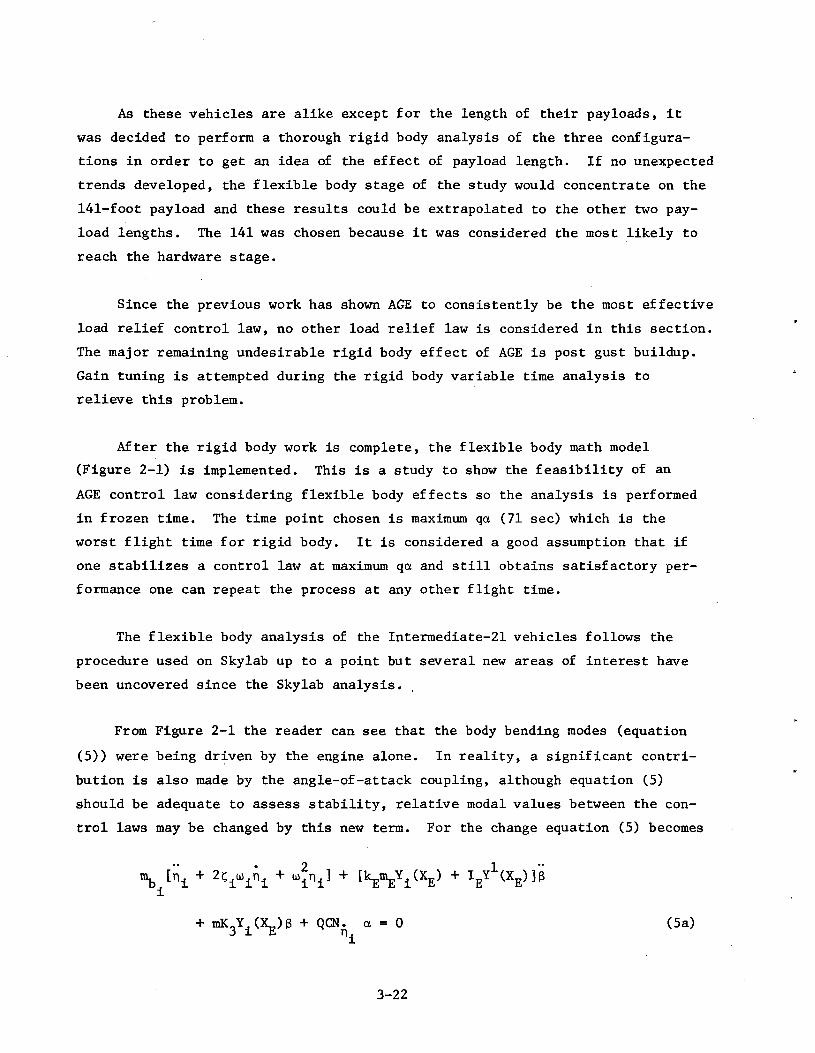
From Figure 2-1 the reader can see that the body bending modes (equation
(5)) were being driven by the engine alone. In reality, a significant contri-
bution is also made by the angle-of-attack coupling, although equation (5)
should be adequate to assess stability, relative modal values between the con-
trol laws may be changed by this new term. For the change equation (5) becomes
\['«± + 2Wl + "i"!1 + IkEBEYl(XE) + VX'J*
+ QCN. a = 0 (5a)
3-22
In the Skylab work and during the first part of the Intermediate-21 work
the accelerometer sensor was located at the first and second interstage (36.6 m).
For implementation reasons it was desired to examine the feasibility of locating
it at the instrument unit (62.2 m on this vehicle). This is considered in this
section.
3.4.2 Rigid Body Results
A wind study was performed on all three payloads, comparing AC against AGE
for each payload. The family of synthetic winds has 95-percentile profiles,
99-percentile shear buildups and gusts occurring at flight times from 55 seconds
to 120 seconds. Added to these is an idealization of the AS-504 measured wind
to one plane. Several of these winds are shown in Figure 2-2. The results of
the synthetic wind study for the 141-foot payload are shown in Figure 3-11. It
can be seen that the peak a and 3 (variable time) occur at maximum q*a for AC
while the AGE control law has its 3 peak at maximum q (81 sec) and a peak at
maximum q*a. This justifies the choice of 71 sec as the frozen time point for
the flexible body study.
Figure 3-12 shows the peak a and 3 associated with each payload length at
maximum q*a. Note the dramatic reductions in a and 3 which are caused by the
AGE control law. Gimbal angles no longer approach the limits with the AGE
control law. They are reduced 47 to 56 percent, depending on the payload length.
Reductions in angle-of-attack are about the same for each payload, roughly 55j
percent. Figure 3-12 points out a significant feature of AGE; i.e., the more
severe the load or controllability problem the greater percentage reductions
AGE yields.
Other results presented in reference 13 show that AGE reduces the a and 3
induced by the AS-504 measured wind to a lesser percentage than those quoted
above. Angle-of-attack is reduced about 28 percent and gimbal angle is reduced
from 7.5 percent to 14 percent. A 95-percentile profile reverse 99-percentile
shear wind causes little problem to either AC or AGE.
The problem of post gust buildup was also attacked in this analysis. It
was believed that gain tuning would eliminate or reduce this problem and that
3-23
14
12
10
2
a. - AGE
MAX qa MAX q
6 - AGE
40 50 60 70 80 90
GUST TIME (sec)
100 110 120 130
Figure 3-11. RIGID BODY VARIATION OF PEAK a, e WITH TIME OF GUST - 95%SYNTHETIC WIND, 141-FOOT PAYLOAD
10.0
I/IUJ
. UJs5.0-
0-c
A A A a - AC
• -O 8 - AC
> ' 107 141 187
PAYLOAD LENGTH (ft)
Figure 3-12. RIGID BODY a, @ RESPONSES VS PAYLOAD LENGTH - GUST AT MAX Qa - 95%SYNTHETIC WIND
3-24
turned out to be a correct assumption. By using a straight line ramp for the
AGE gains so that the booster's closed loop natural frequency (u> ) and damping
ratio (? ) were held nearly constant as the vehicle parameters (mass, aero-
dynamics, etc.) were changing, it proved possible to eliminate the undesirable
buildup. All the previous rigid body results used these gains. Examination
of time traces in reference 11 will show that the characteristic late flight
a, 6 (and bending moment) buildups have been eliminated.
3.4.3 Flexible Body Results
3.4.3.1 Feasibility Study. For reasons given above the flexible body analysis
concentrated on the 141-foot payload at the frozen time point 71 seconds. Much
of the effort on this study was in designing suitable filters at this time
point. At this point guidelines for the study gave the accelerometer location
at 36.6 meters. The math model was the one shown in Figure 2-1.
Reference 13 shows the results of this study. Root-locus and Nyquist pro-
grams established the stability of each payload and a hybrid simulation (2-D)
was used to verify the results of the stability programs. The set of filters
designed for the 141-foot payload proved to be usable for the 107- and 187-foot
payloads. Gain and phase margins can be found in reference 13. AGE margins
are lower than AC throughout. Angle-of-attack and gimbal angle maximums con-
tinued to show the same dramatic reductions with AGE as they showed in the
rigid body study. It should be emphasized that AGE filters are low order pre-
liminary and designed only to show feasibility. Improvements in the gain and
phase margins should be possible with carefully designed, higher order filters.
3.4.3.2 Angle-of-Attack Coupling. As described in subsection 3.4.1 the effect
of a on the bending modes is an important problem. When the math model is so
altered, the bending mode accelerations are increased sharply with both AC and
AGE. The net result is that AC and AGE have about the same modal acceleration
magnitude (ref. 13).
3.4.3.3 Accelerometer at IU. Without changing the simple second-order filters
of subsection 3.4.3.1, the accelerometer was relocated to the IU of this vehicle.
3-25
The modes remained stable but the relative magnitudes of n-i and ru were
changed since the first mode influence coefficient at the IU has about half
the magnitude there as it does at the interstage (ref. 2). Slight oscilla-
tion was displayed by some of the rigid body variables but this was attributed
to the use of the filters designed for an accelerometer mounted at the inter-
stage instead of the IU.
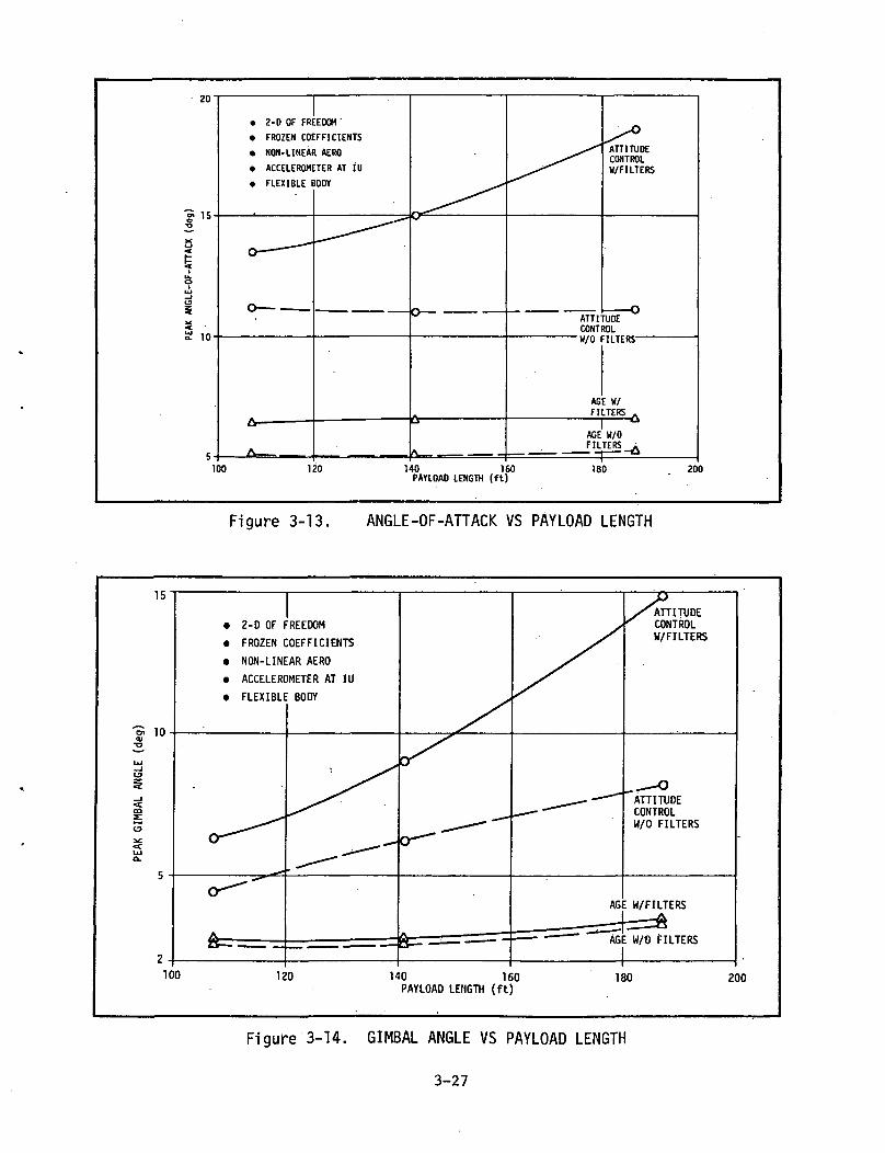
3.4.3.4 Parametric Responses. Figures 3-13 and 3-14 show the peak a and g
values of all three payloads with all these past assumptions in force. Note
the high reductions in a and 3 (about 67 percent for the 141-foot payload).
These results were taken from the 2-D hybrid simulation with flexible body
modes, frozen coefficients, non-linear aerodynamics, and the accelerometer
located at the IU.
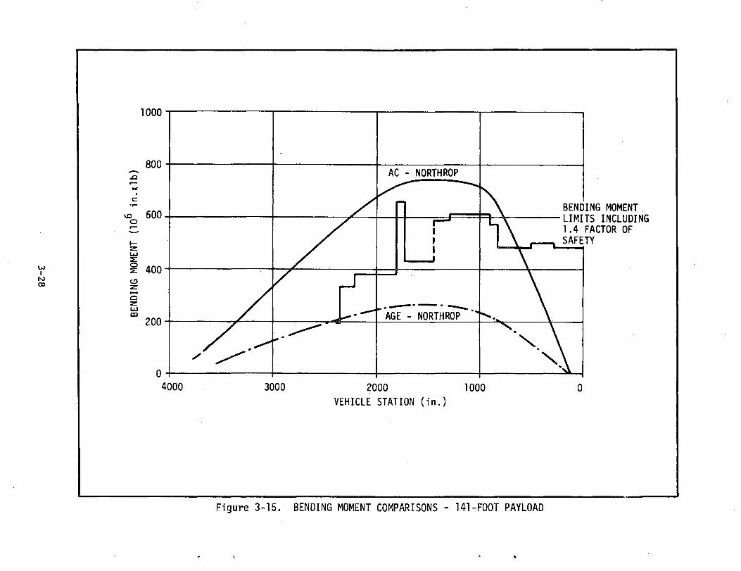
3.4.3.5 Bending Moments. To get some idea of the bending moments caused by
the a, 3 values, Figure 3-15 has the bending moments along the vehicle (141-
foot) for AC and AGE. For comparison it also has the bending moment limits
referenced on the graph. The bending moment limits were obtained for the
Saturn V and they terminate around 2400 inches since no limits are known for
the 141-foot payload substituted for the present S-IV third stage.
The AGE control law reduces the bending moment by as much as 70 percent,
but does not conclusively show the bending moments will not exceed the limits.
In addition, flexible body contributions to bending moment (equation (1)) are
not included for lack of data. They usually add about 10 percent to the value
(ref. 9). (However in section 3.4.3.2 it was established that AC and AGE have
about equal n. so they will not change the relative values of the bending
moments.) On the other hand these are frozen time results; 20 to 30 percent
conservative. Furthermore, the bending moment limits are for a manned vehicle
(1.4 factor of safety) whereas the Intermediate-21 will be unmanned (1.25
factor of safety) (ref. 10). It is believed the net results would let the
vehicle stay within the bending moment limits, but the problem needs further
study.
3-26
20
S1 15T3
*C<_>
«t
^
Ul_lt3
S 10
2-D OF FREEDOM '
FROZEN COEFFICIENTS
NON-LINEAR AERO
ACCELEROMETER AT IU
FLEXIBLE BODY
ATTITUDECONTROLW/FILTERS
o-ATTITUDECONTROL
-W/0 FILTERS-
AGE W/FILTERS
AGE W/0FILTERS
100 120 140 160PAYLOAD LENGTH (ft)
180 200
Figure 3-13. ANGLE-OF-ATTACK VS PAYLOAD LENGTH
15
10
100
• 2-D OF FREEDOM
• FROZEN COEFFICIENTS
• NON-LINEAR AERO
• ACCELEROMETER AT IU
• FLEXIBLE BODY
120 140 160PAYLOAD LENGTH (ft)
ATTITUDECONTROLW/FILTERS
ATTITUDECONTROLW/0 FILTERS
AGE W/FILTERS
=f==AAGE W/0 FILTERS
180 200
Figure 3-14. GIMBAL ANGLE VS PAYLOAD LENGTH
3-27
O<O_l<D.OO
Ioozoco•—icc<Q_OOCJ3
i—<Oz:UJCQLOIco(U3CD
Ol) 1N3WOW 9NIQN38
3-28
3.4.3.6 Typical Responses. To illustrate the comparative effects of AC and
AGE control laws on a vehicle with nonlinear aerodynamics, simplified filters
and two flexible body modes driven by aerodynamics and engines, Figures 3-16
and 3-17 are included. These responses are taken from frozen time. They show
the sharp reductions in a and B that AGE affords. The AGE control law allows
the heading error (4>) to diverge from zero (into the wind) as it encounters
the wind. This is the mechanism that permits the vehicle to incur lower
bending moments during flight. By contrast <|> is away from the wind during AC
flight. Note that the bending accelerations (n.) are about equal in the first
mode but AGE accelerations are higher in the second mode.
3,4.4 SUMMARY
3.4.4.1 Conclusions.
• On any of the Intermediate-21 configurations AGE reduces bendingmoments by more than one-half the corresponding AC value.
• Under AGE control none of the configurations' gimbal angles exceedthe current limits (5.15 deg). However, the 141-foot and 187-footpayloads do exceed 5.15 degrees gimbal angle with AC control.
• Flexible body effects on the accelerometer sensor are controllableby simple filters. Stability margins are lower than those obtainedby an AC control law.
• Flight path drift and a, 3 post gust buildup can be controlled by gaintuning coupled with a path velocity feedback.
3.4.4.2 Recommendations.
• Further filter and stability work should be conducted with theaccelerometer at the IU.
• Additional effort is required to define filters to achieve beststability margins for all flight times during first stage burn.
3-29
u0>tn
I—I—
I—I—
h
H—
I—I—
I—I—
H
H—
I—I—
I
H 1
1 1
1 1
1 1
1.
I—I—
I—I
1
1—
I—I
-\—1—
I—I—
I—I—
I—I—
I
IVAA
1 1
1 1
h
O :
0)
1 1
1 1
1 1
1 h
a
oo-
X
s:
oo
a
>-c
aa
:z i a
LU
_
o U
J <
C3
LU
00 _J
S
00
CC
<Ji-«Q
i-i«
t>-< t—
>-• X
LJ
bos u
iz:
Z 1
-1 _
l i— i
a: uj o: u — i
t-M
(
zo
oo
z
COC£
LLlI—coC
D
OCOIOOXOOVO
r—0)301
3-30
i~tiH
•™wta.
P"H
K=9
=»
U-H
....
J.U
-J
J*u
:-x-s•LJ-J ~
:
^-^x
J-L
J
.-•;j/•>^^UIJ
^-—. •
t*-H
jr
^\1-vx.l)/'
'
uIJH
o/i..-.-
(*"^x^I*-H
uC
—
-«.!u
UJ^
.1 '
, rJ-« "•> l
vlH:fi1: -ei
= ?
=' i
T
, -;
4;i01
70
•CMfj
I?itIOincsi
H.J-) •^:.
uOl
in.._=SIuO
J^«
U«
-j . ~;
-s=•"••H
rr:-
.-- '
•-1-1
^v^ Jv;:~~="";jj
r^
-;
^^d
._ -
— —
*
-: . -
U-"
r-.=
jJUnnv i-milm
l
*— "SYNTHETIC WIND
•.milBfi/a°".X<i
51
C
UJ C
sc
h- •2; ^
jj £N
l
J_ C
— ;
HiIII!
-->,ul_Cs>C
5§
3 U
a -
= e-< >3 U
- *.
3 C
-.—
mil1!litHI!'x
\\\V<
1J>>i)Oi a
:U
JJ<
£
C U
JJ Z
J >——
11E
O- Z
teIs
1 f
1ft 1
14--(--=I ~
^-
:
y ' •1oinCM
1 • .0
"
,•-— '
1
~:
CMC0U
CMt0
.^
1S-.
--* •:.
>
.
^-
1
1fCN
J
4rrr-C\\
41•o-I^~—(
tt-e-i..1
L:~
~.
J "
=
_^
i—:—":
S-.-
"• '
;-/
7-:.
1—O£i•51-
^_,
VD
<JOC
O
J-:«tce:
2:
oo•Z*
O1—<cl— l
OUJ1
aos:rt•y
l— 1
SCD
<c^,1n£3•
^
3-3
1
Section IV
OVERALL LOAD RELIEF CONCLUSIONS AND RECOMMENDATIONS
4.1 CONCLUSIONS
Bending moments are lower on every configuration when an AGE controllaw is used. When compared with the baseline AC law reductions aretypically 10-30 percent with measured winds and 30-60 percent withsynthetic winds. It is believed that the key to the success of AGElies in elimination of the preprogrammed attitude command profile.
Drift and drift rate are lower under AGE control than under the ACcontrol.
Severe ramp transients and post-gust buildups can be eliminated byproper gain choices.
Measured winds cause lower loads than the worst case synthetic windbut AGE is less effective in reducing loads caused by measured winds.
An AGE control law will function just as well in reducing bendingmoments when flexible body effects are considered. However gainand phase margins are lower with the simplified filters. An increasein the order of the filters should provide adequate margins for theAGE control law.
4.2 RECOMMENDATIONS
Additional work should be directed toward flexible body problems,especially filters. Filters are needed that will give suitableresponses and stability margins and be good throughout first stageflight.
Since the alpha meter can give equivalent rigid body load reductionsa study should be made to determine the trades present betweenacceleration and angle-of-attack feedbacks. Problems associated withhardware qualification, location, performance and flexible body inter-actions need consideration.
A cost analysis is needed to compare cost of control system modifica-tions against cost of structural modifications for beefup of thebooster and against launch limitations and turn around expenses.
Reliability of the sensors involved should be compared. Anotherrelated area of future study is engine failure capability.
4-1
Section V
REFERENCES AND BIBLIOGRAPHY
1. The Boeing Company, "Design Data Report - Int-21 Launch Vehicle withMDAC Phase II Payload (107-Foot Long - Clean)", Attachment to Memo5-9406-INT-21-27, July 24, 1970.
2. The Boeing Company, "Design Data Report - Int-21 Launch Vehicle with MDAC141-Foot Payload Configuration", Attachment to Memo 5-9406-INT-21-27,July 24, 1970.
3. The Boeing Company, "Design Data Report - Int-21 Launch Vehicle with MDACReusable Nuclear Shuttle (RNS) Payload, Attachment to Memo 5-9406-INT-21-27,July 24, 1970.
4. Chichester, D. E., "Application of Saturn V Intermediate Launch Vehiclesto Space Station/Space Base Missions", Volume 4 - Controls, The BoeingCompany, 5-9410-H-087-4, October 30, 1970.
5. The Boeing Company, "Digital Program BHA0030-D Saturn V/S-IC FlightDynamics" (Digital Computer Program).
6. The Boeing Company, "Application of Saturn V Intermediate Launch Vehiclesto Space Station Missions - Final Technical Report", D5-15804-2, August 10,1970.
7. Mayeaux, H. J., "Load Relief Control Law Investigation and Data Report forSaturn V/Apollo Launch Vehicle", Northrop-Huntsville, TR-795-8-419,September 1968.
8. Kiefer, H., "Rigid Body Load Relief Study For S-1B-AAP Configuration (WetWorkshop)", Northrop-Huntsville, TR-795-9-653, November 1969.
9. Cerny, 0. P., Foster, L. W. and Sharp, J. B., "Load Relief Attitude Controlof the Skylab Launch Vehicle", Northrop-Huntsville, TR-795-795, October 1970.
10. Lane, L. G., "Intermediate-21 Launch Vehicle Preliminary Description ForPhase B Space Station Design", The Boeing Company, D5-15583, August 22,1969.
11. Sharp, J. B., "Intermediate-21 Rigid Body Response Study", Northrop-Huntsville, 7951-70-30, August 27, 1970.
12. Rheinfurth, M., "The Alleviation of Aerodynamic Loads on Rigid SpaceVehicles", Technical Memorandum X-53397, George C. Marshall Space FlightCenter, Huntsville, Alabama.
13. Sharp, J. B., "Intermediate-21 Load Relief Attitude Control", Northrop-Huntsville, TR-795-895, March 1971.
5-1
14. Livingston, J. M. and Redus, J. R., "Load Reducing Flight Control Systemsfor the Saturn V with Various Payloads", AIAA Paper #68-843, August 1968.
15. "Redefinition of Saturn IB Synthetic Wind Profile", MSFC Memo R-AERO-Y-66-65, September 10, 1965.
16. "FPS-16 Radar/Jimisphere Wind Data Measured at the Eastern Test Range",NASA TMX-53290, December 22, 1965.