Curiosity, the big rover of this artist's concept depicts the moment that NASA's Curiosity rover touched down onto the Martian surface. Image credit: NASA/JPL-Caltech
Shri G. Agarwal NASA – Jet Propulsion Laboratory, California Institute of Technology
• Thank you Tamura-san and JAXA for your invitation. It’s always a pleasure to visit Tsukuba.
• Our congratulations to JAXA on the 26th anniversary of the MEWS Workshop!
• JAXA is our valued partner in NASA Electronic Parts Assurance Group (NEPAG) activities
• This talk is about NASA space component strategies for today and tomorrow.
• It is divided into four parts: – Present Issues – Changing landscape – Challenges associated with infusion of state-of-the art complex devices into
the QML system – the Class Y initiative – Future
2
NASA Electronic Parts Assurance Group (NEPAG) NEPAG PARTICIPANTS
3
Space Component Strategies Today Existing Military Documents
• Microcircuit Devices
– Current Activities
§ MIL-STD-883, Test Method (TM) 2017 (Visual Inspection for Hybrids) u Changes were discussed in last Task Group meeting u The TM is to be updated
§ MIL-HDBK-217, Reliability Prediction u The most recent version is Revision F, Notice 2, released in 1995 u No change in status
§ MIL-STD-883, Test Method 1014 (Hermeticity) u Clarified Krypton leak test for flat-top crystals u Optical leak test
§ MIL-PRF-38534 u Add Photonics?
§ MIL-PRF-38535, Revision K (Draft) u Introduces Class Y
4
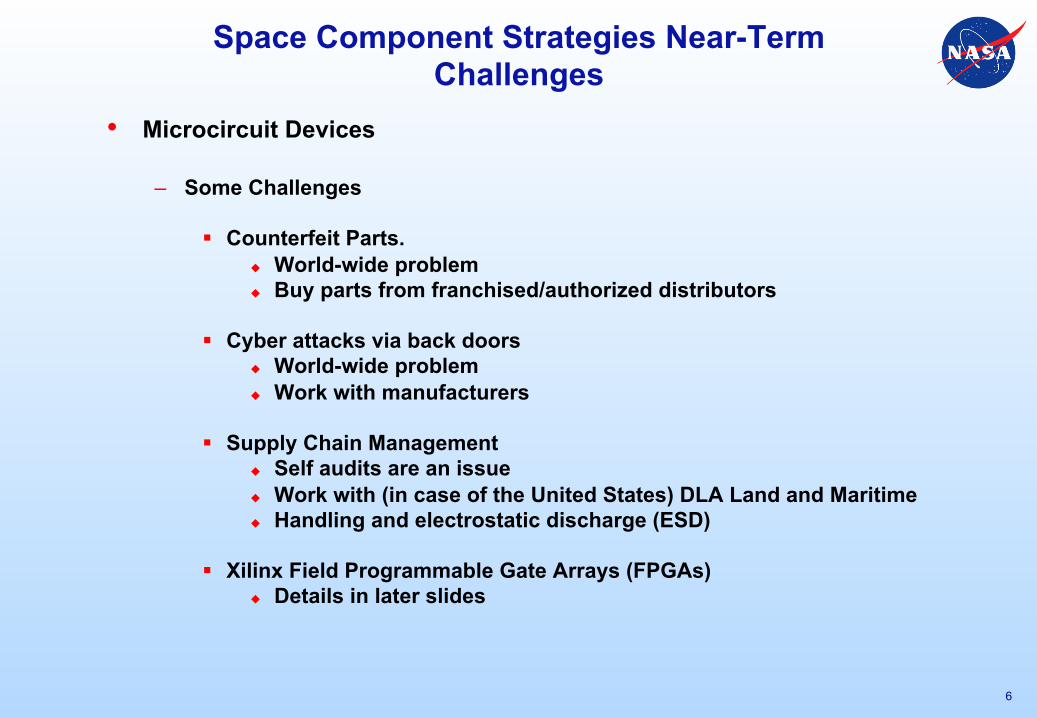
Space Component Strategies Near-Term Challenges
• Microcircuit Devices
– Some Challenges
§ Dual-use Technology u Infusion of selected commercial device functions into QML u Parts might not operate over the full military temperature range u There may be hot spots on the die (use thermal imaging)
§ Testing High-speed Devices u Request new JEDEC task group to address this challenge
« What can be tested? « How? « What is good enough?
u Consider forming consortium with manufacturers and other users
§ Upscreening of plastic encapsulated microcircuits (PEMs), lower grade hermetic parts
u Many challenges: « electrical testing, « type of burn-in, « Glass-transition temperature (for PEMs), « third-party management, etc.
u Several Variations
5
Space Component Strategies Near-Term Challenges
• Microcircuit Devices
– Some Challenges
§ Counterfeit Parts. u World-wide problem u Buy parts from franchised/authorized distributors
§ Cyber attacks via back doors u World-wide problem u Work with manufacturers
§ Supply Chain Management u Self audits are an issue u Work with (in case of the United States) DLA Land and Maritime u Handling and electrostatic discharge (ESD)
§ Xilinx Field Programmable Gate Arrays (FPGAs) u Details in later slides
6
Space Component Strategies Near-Term Challenges
• Microcircuit Devices
– Current Activities
§ Burn-in screening and life test u Clarify requirements u Insure proper implementation u Details in later slides
§ Base-Metal Electrode (BME) Capacitors u Develop a proper screen to allow for their use in space products u Several evaluation efforts in progress u Also, see page 22
§ Column Grid Arrays (CGAs) u Effect on device performance u Details in a later slide
§ Infusion of new technology into U.S. Department of Defense (DoD)
standards u Created a new category (Class Y) u MIL-PRF-38535, Revision K introduces Class Y u Details in later slides
7
Infusion of New Technology into MIL Standards The “Class Y” Initiative
• Advances in packaging and device technology are happening rapidly.
• How do we enable space flight projects to benefit from the newly developed devices?
• NASA is leading a G12 initiative, called Class Y, for infusing this new type of complex devices into military/space standards. Class Y is envisioned as a new category of ceramic-based non-hermetic microcircuits, such as the Virtex-4 and Virtex-5 field programmable gate arrays (FPGAs) offered by Xilinx Corporation.
• Creation of a new class of microcircuits (such as Class Y) has required considerable effort. It must be coordinated with manufacturers, government agencies, prime contractors, and other interested entities (e.g., academia). Also, we need to ensure that all aspects of packaging configuration are adequately covered by the military documents, such as MIL-PRF-38535 and MIL-STD-883. These packaging aspects include flip-chips, underfills, adhesives, column attaches, and others
• New test methods must be created and the existing standards updated as necessary.
8
Infusion of New Technology into MIL Standards Adding Class Y to Microcircuits Specification
• Microcircuits specification, MIL-PRF-38535
Next revision (K) is in preparation Introduces Class Y Second draft available now Comments were due by June 24, 2013
• Acknowledgements
Special thanks to DLA-VA Thanks to everyone including task group (TG) members
and advisors
• Class Y Status
See the next sheet
9
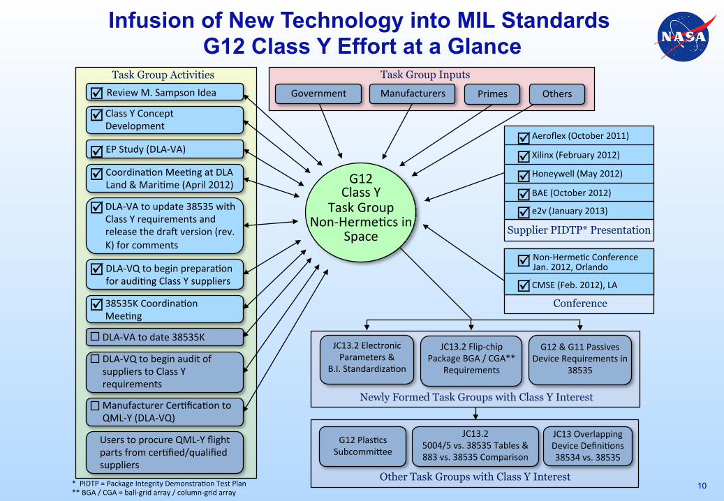
Infusion of New Technology into MIL Standards G12 Class Y Effort at a Glance
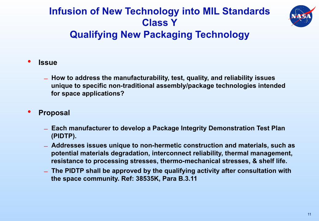
Infusion of New Technology into MIL Standards Class Y
Qualifying New Packaging Technology
• Issue
How to address the manufacturability, test, quality, and reliability issues unique to specific non-traditional assembly/package technologies intended for space applications?
• Proposal
Each manufacturer to develop a Package Integrity Demonstration Test Plan (PIDTP).
Addresses issues unique to non-hermetic construction and materials, such as potential materials degradation, interconnect reliability, thermal management, resistance to processing stresses, thermo-mechanical stresses, & shelf life.
The PIDTP shall be approved by the qualifying activity after consultation with the space community. Ref: 38535K, Para B.3.11
11
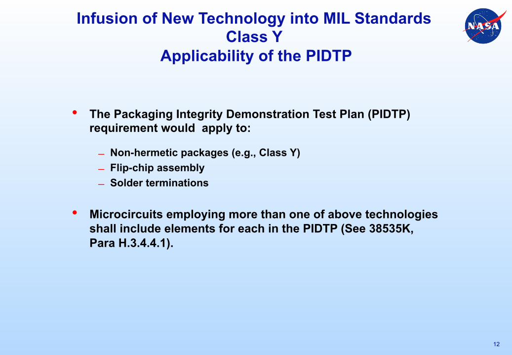
Infusion of New Technology into MIL Standards Class Y
Applicability of the PIDTP
• The Packaging Integrity Demonstration Test Plan (PIDTP) requirement would apply to:
Non-hermetic packages (e.g., Class Y) Flip-chip assembly Solder terminations
• Microcircuits employing more than one of above technologies shall include elements for each in the PIDTP (See 38535K, Para H.3.4.4.1).
12
Screening Requirements in Draft 38535K Class V vs. Class Y
• Screening
Same for both V and Y except the differences related to hermeticity vs. non-hermeticity.
• Column Attached Parts (as offered by Manufacturers)
100% DC electricals post column attachment (same for V and Y)
Visual inspection (same for V and Y) No additional screening requirement
for V or Y
13
The Hubble Space Telescope (HST) is a 2.4-m (7.9-ft) aperture space telescope. It was carried into low Earth orbit by a Space Shuttle in 1990, and it remains in operation.
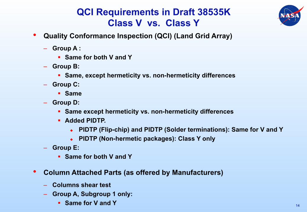
QCI Requirements in Draft 38535K Class V vs. Class Y
• Quality Conformance Inspection (QCI) (Land Grid Array) – Group A :
§ Same for both V and Y – Group B:
§ Same, except hermeticity vs. non-hermeticity differences – Group C:
§ Same – Group D:
§ Same except hermeticity vs. non-hermeticity differences § Added PIDTP.
u PIDTP (Flip-chip) and PIDTP (Solder terminations): Same for V and Y u PIDTP (Non-hermetic packages): Class Y only
– Group E: § Same for both V and Y
• Column Attached Parts (as offered by Manufacturers) – Columns shear test – Group A, Subgroup 1 only:
§ Same for V and Y 14
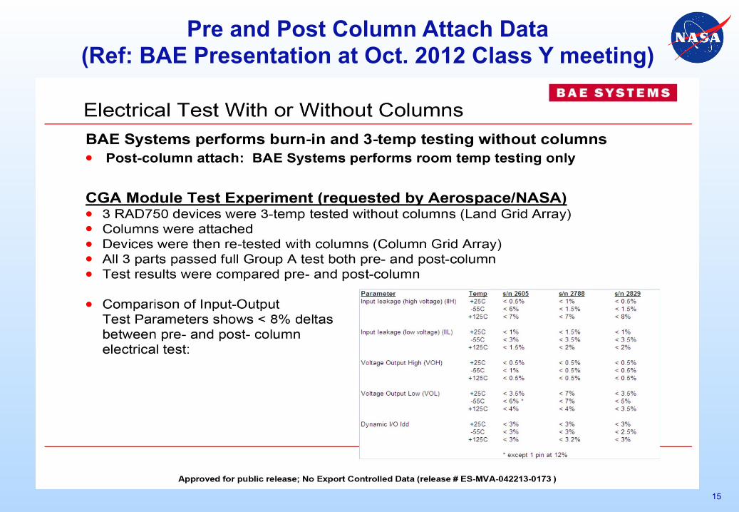
Pre and Post Column Attach Data (Ref: BAE Presentation at Oct. 2012 Class Y meeting)
15
National Aeronautics and Space Administration 2 16
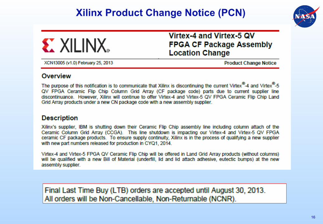
Xilinx Product Change Notice (PCN)
Xilinx PCN CF to PN Package Change
17
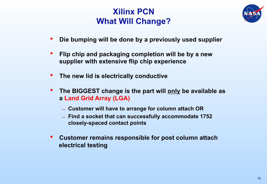
Xilinx PCN What Will Change?
18
• Die bumping will be done by a previously used supplier
• Flip chip and packaging completion will be by a new supplier with extensive flip chip experience
• The new lid is electrically conductive • The BIGGEST change is the part will only be available as
a Land Grid Array (LGA) Customer will have to arrange for column attach OR Find a socket that can successfully accommodate 1752
closely-spaced contact points
• Customer remains responsible for post column attach electrical testing
Xilinx PCN The CF to CN Transition
19
• Availability
IBM still operates until Q3 2014. Xilinx last time buy ended August 2013.
• For Kyocera Qualification
Doing feasibility build and test on representative samples in preparation for qualification builds
By the time qualification is completed and the Qualifying Activity (QA) has given approval, the single-event effects immune reconfigurable (Virtex 5QV) CN parts are expected to be available immediately.
• It is planned to have Class Y (non-hermetic space grade) fully incorporated in M38535 in time to allow Xilinx to qualify as part of their overall qualification program.
Issues with Microcircuits Burn-in (BI) Screening
• BI is the key screening step – the whole industry relies upon burn-in as a critical screening step to weed out product infant mortality.
• The same BI circuit is used for life test (reliability assessment)
• Our recent audit and specification review work has shown that the microcircuits BI screening requirements as specified are out of date and have multiple interpretations.
• Can’t burn-in the new high speed devices at or close to their speeds because – Parts are specified in hundreds of MHz to several GHz – But, the burn-in equipment is limited to ~ 6MHz
• MIL-M-38510 slash sheets used to specify the burn-in circuits. But, the performance specs (SMDs) don’t.
– NASA has recommended that the requirement to supply the burn-in circuits at initial qual review be added to MIL-PRF-38535, Appendix H, Para H.3.4.6.
20
Issues with Microcircuits Burn-in (BI) Screening
• Should review the element level burn-in of the microcircuits used in hybrids, such as DC/DC converters, crystal oscillators, and others.
• NASA and others brought up these issues at the JC13 meeting and a Task Group was formed to address and provide guidance on these issues. Ref: S. Agarwal presentation at the Space Parts Working Group (SPWG), 2013.
• Pool together the expertise in this area
• Any updates made to the MIL specs should be based on test data.
• A dialog with the burn-in equipment manufacturers would be necessary
• Limited test data should be taken by the users – To validate our understanding of the fundamentals of burn-in
21
Monolithic vs. Hybrid Microcircuits and Related Issues Standard
Microcircuits
# Elements
Mil Spec
Issues: (First Reported by NASA)
Mitigation:
BME Used?
Mitigation
Monolithics Single MIL-PRF-38535 Capacitors Inside IC Packages Signal Integrity capacitors Used In IC packages Added capacitor screening requirements In 38535 Spec (Para 3.15) Yes, but not tested to 3.15 (Xilinx V-4/V-5 FPGAs, Class Y candidates) Evaluate BMEs (NASA, Aerospace, Suppliers, ESA, JAXA) Double Derating ?
Hybrids Multiple MIL-PRF-38534 Single Die Hybrids Manufacturers building single die hybrids Encouraging suppliers to also get 38535 Certification (M.S. Kennedy has already received it.) Yes, but meet existing element evaluation requirement which are not as stringent as for 38535. Stop use until evaluation done. (Ref: G12 letter to DLA)
Changes in Last Few Years: The boundary between monolithics and hybrids has become blurred.
A New Issue: No MIL capacitors to satisfy the needs of new high-speed, low voltage designs. They are using Commercial BME (Base Metal Electrode) capacitors with unproven space heritage. Affects Class Y.
22
Space Component Strategies for Tomorrow Evaluating the next generation of (Nano) Devices
• The next generation of nanodevices will be built on 450-mm wafers in a 28-nm and smaller feature sizes. This will increase device complexity tremendously.
• As the next-generation nano devices are developed, the candidates for infusion into the military standards should be identified and evaluated.
• The evaluation for reliability would follow the requirements as given in MIL-PRF-38535, Appendix H.
• The radiation hardness evaluation requirements are given in MIL-PRF-38535.
• It is anticipated that most of the new devices would be microcircuits. Such devices should be classified in one of the quality assurance levels as defined in MIL-PRF-38535.
• In case any of the devices is a hybrid circuit, the classifications for those devices should be per the quality assurance levels as defined in MIL-PRF-38534.
• Ref: S. Agarwal, “Infusion of Next-Generation Nano Devices into Military/Space Standards,” Advanced Technology Workshop on Packaging Next Generation of Nano Devices, Albany, NY, April 30 – May 1, 2013.
23
Concluding Remarks
• The Class Y experiment has shown that it takes a considerable amount of time and effort to infuse new technology into the QML system.
• The next step for Class Y would be the release of MIL-PRF-38535, Rev. K.
• As the next generation nano devices are developed, the candidates for infusion into the military standards should be identified, and evaluation of those candidates should be started as early as possible.
• The military standards should be reviewed on a periodic basis and updated to accommodate the unique features of the new devices.
24
Future Challenges
• Who knows? BUT it will be:
?– Smaller and lighter – More efficient – Faster – Changing continuously – Desirable BUT perhaps not space-worthy
• And we need to be:
– Flexible and innovative – Open-minded – Willing to expand the definition of “part” as integration puts more system
levels on a chip or in a package
25
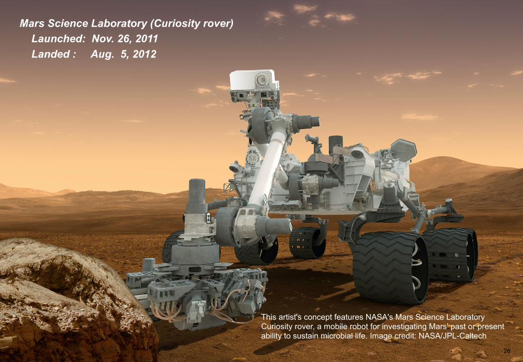
Mars Science Laboratory (Curiosity rover) Launched: Nov. 26, 2011 Landed : Aug. 5, 2012
26
This artist's concept features NASA's Mars Science Laboratory Curiosity rover, a mobile robot for investigating Mars' past or present ability to sustain microbial life. Image credit: NASA/JPL-Caltech
27
http://nepp.nasa.gov
ACKNOWLEDGMENTS The research described in this publication was carried out, in part, at the Jet Propulsion Laboratory, California Institute of Technology, under a contract with the National Aeronautics and Space Administration. Help is gratefully acknowledged from Dr. Charles Barnes, Roger Carlson, Joon Park, and Michael Sampson. Copyright 2013 California Institute of Technology. Government sponsorship acknowledged.


![Conservation Strategies For Today Global Real Estate Market Pp[1]](https://static.documents.pub/doc/80x56/55866024d8b42a99308b46ff/conservation-strategies-for-today-global-real-estate-market-pp1.jpg)


