--- b NASA TECHNICAL NOTE NASA TN D-4090 0 o* 0 P LOA = z c KIR 4 c/) 4 z NONLINEAR FLEXURAL VIBRATIONS OF THIN-WALLED CIRCULAR CYLINDERS by Dauid A. Euensen Langley Research Center Langley Station, Hampton, Vu. 5 NATIONAL AERONAUTICS AND SPACE ADMIJISTRATION WASHINGTON, D. C. AUGUST 1967 https://ntrs.nasa.gov/search.jsp?R=19670024117 2018-06-19T11:16:15+00:00Z
Transcript
---
b
N A S A T E C H N I C A L NOTE N A S A TN D-4090
0 o* 0
P LOA= z c KIR
4 c/)
4 z
NONLINEAR FLEXURAL VIBRATIONS OF THIN-WALLED CIRCULAR CYLINDERS
by Dauid A. Euensen
Langley Research Center Langley Station, Hampton, Vu. 5
N A T I O N A L AERONAUTICS A N D SPACE A D M I J I S T R A T I O N W A S H I N G T O N , D. C. AUGUST 1967
Langley R e s e a r c h Cen te r Langley Station, Hampton, Va.
NATIONAL AERONAUTICs AND SPACE ADMINISTRATION
Far sale by the Clearinghouse far Federal Scientific and Technical Information Springfield, Virginia 22151 - CFSTI price $3.00
NONLINEAR FLEXURAL VIBRATIONS OF
THIN-WALLED CIRCULAR CYLINDERS
By David A. Evensen Langley Research Center
SUMMARY
The nonlinear flexural vibrations of thin-walled circular cylinders are analyzed by assuming two vibration modes and applying Galerkin's procedure. This procedure resuIts in two coupled nonlinear differential equations for the modal amplitudes. Only one of these differential equations contains a forcing function, since the applied loading is so chosen that only one mode (the driven mode) receives external excitation.
Approximate solutions for the modal response are obtained by the method of averaging. One such solution involves the response of only the driven mode; a subsequent stability analysis shows that this single-mode response is unstable for certain combinations of amplitude and frequency. In this unstable region, it is necessary to consider the coupled-mode response involving both modes, and an approximate solution is presented for this problem.
The analysis is in qualitative agreement with the available experiments on the nonlinear vibrations of cylindrical shells, and it exhibits several features that are thought to be characteristic of nonlinear flexural vibrations of thin shells of revolution.
INTRODUCTION
Current design of missiles and launch vehicles relies extensively on the use of thin-walled cylindrical shells as the primary structure. During powered flight, these cylindrical structures are often caused to vibrate to large amplitudes. This problem of large-amplitude vibrations has given rise to a number of theoretical studies of the nonlinear vibration of thin cylindrical shells. (See refs. 1 to 4, for example.) The basic approach used in these studies is to assume the shape of the deflection in space, that is, the shape of the vibration mode, and then to derive a corresponding amplitude-frequency relationship.
In a pioneering work, Reissner (ref. 1) isolated a single half-wave or lobe of the vibration mode and analyzed it. His results indicated that the nonlinearity could be either of the hardening (frequency increasing with amplitude) o r softening (frequency
decreasing with amplitude) type, depending upon the geometry of the lobe. Reissner's work was followed by a similar study by Chu (ref. 2).
Chu employed the same assumed mode shape as reference 1but analyzed ihe problem somewhat differently. His analysis indicated that the nonlinearity was Blways of the hardening type, in which case the frequency increases with the amplitude of vibration.
One reason for the different results of references 1 and 2 was discovered by Cummings (ref. 3). Cummings employed a Galerkin procedure and found that the results varied with the region of integration. When the integration was carried out over a single half-wave o r lobe, the results obtained were the same as those of Reissner. When the integration was extended over the entire shell, the results were similar to those of Chu (ref. 2). Thus, it appeared that Reissner's results were characteristic of curved panels, whereas Chu' s calculations were apparently applicable to complete cylindrical shells. Chu' s calculations subsequently received further confirmation from a study by Nowinski (ref. 4).
A striking feature of the results from references 2 to 4 is the conclusion that the nonlinearity always causes an increase in frequency with amplitude. On the other hand, recent experiments (refs. 5 to 7) indicate that the vibration frequency generally decreases with amplitude. This difference between the trends indicated by theory and experiment led to a reexamination of the previous analyses and thus originated the present study.
A review of the previous analyses revealed that references 1to 3 do not satisfy an important continuity restraint on the in-plane circumferential displacement. Conversely, reference 4 satisfies the circumferential restraint but does not maintain zero transverse deflection at the ends of the cylinder. In order to satisfy the continuity condition and still have no deflection at the ends of the cylinder, the present report employs a deflection shape which is a modification of that used in references 1to 3. Unfortunately, this modified mode shape is not moment-free at the ends of the cylinder. Thus, the mode shape used herein has boundary conditions that lie somewhere between simply supported and clamped ends. I
For the most part, references 1to 4 have concentrated on the problem of free vibrations of a single vibration mode. Cummings (ref. 3) formulated a two-mode forced-vibration analysis but gave few quantitative results and was primarily concerned with the weak coupling problem. For weak coupling sf the modes, each mode can vibrate independently. On the other hand, the present analysis treats a case of strong modal coupling, in which both modes vibrate with comparable amplitudes. The two modes involved are classified as a driven mode and its companion mode, both of which'have the same natural frequency. Related studies on nonlinear vibrations of circular rings
2
(ref. 8) and circular plates (ref. 9) have shown the need for including these coupled modes in the study of nonlinear forced vibrations of axisymmetric structures.
In summary, then, the present study involves both free and forced vibrations of a thin-walled circular cylinder. For forced vibrations, coupled motions involving a driven mode and its companion mode are analyzed. The assumed mode shapes satisfy the circumferential continuity condition, but the longitudinal boundary conditions are somewhere between simply supported and clamped. In-plane inertia effects are neglected, and elastic vibrations are assumed. The nonlinearities considered are of the geometric type, originating in the strain-displacement relations. Many features of the analysis are similar to a previous study on rings (ref. 8) and are thought to be characteristic of nonlinear vibrations of thin shells of revolution.
SYMBOLS
a1,a2,a3,a4 stress function coefficients, defined by
a1 = c?Eh
R ( a 2 + p2)2
a?Eha2 = 32p2
o?Eha3 = 16p2
a4 =
amn amplitude coefficient in equation (4a)
Amn(t),Bmn(t) coefficients of the assumed deflection shape
A(T),B(T) slowly varying amplitudes
-A,B average values (over one period) of A(T) and B(T), respectively
C ( 4 generalized force; as defined in equation (Sa) n
Eh'D bending stiffness, Tqc7J E Young's modulus
3
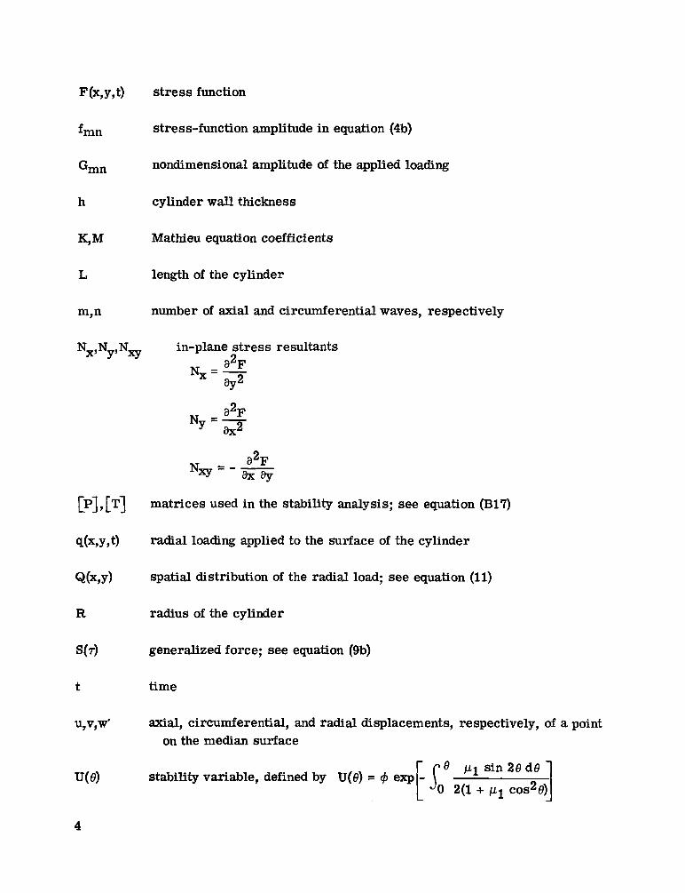
F(x,y,t) stress function
fmn stress-function amplitude in equation (4b)
Gmn nondimensional amplitude of the applied loading
h cylinder wall thickness
K,M Mathieu equation coefficients
length of the cylinder
m,n number of axial and circumferential waves, respectively
Nx,Ny,Nxy in-plane stress resultants a2FNx = aY2
a2F NY = 2
matrices used in the stability analysis; see equation (B17)
radial loading applied to the surface of the cylinder
spatial distribution of the radial load; see equation (11)
radius of the cylinder
generalized force; see equation (9b)
time
axial, circumferential, and radial displacements, respectively, of a point on the median surface
stability variable, defined by U(8) = 9 exp 8 p1 s i n 2 e d e
2(1+ p1 cos%)I
L
CY
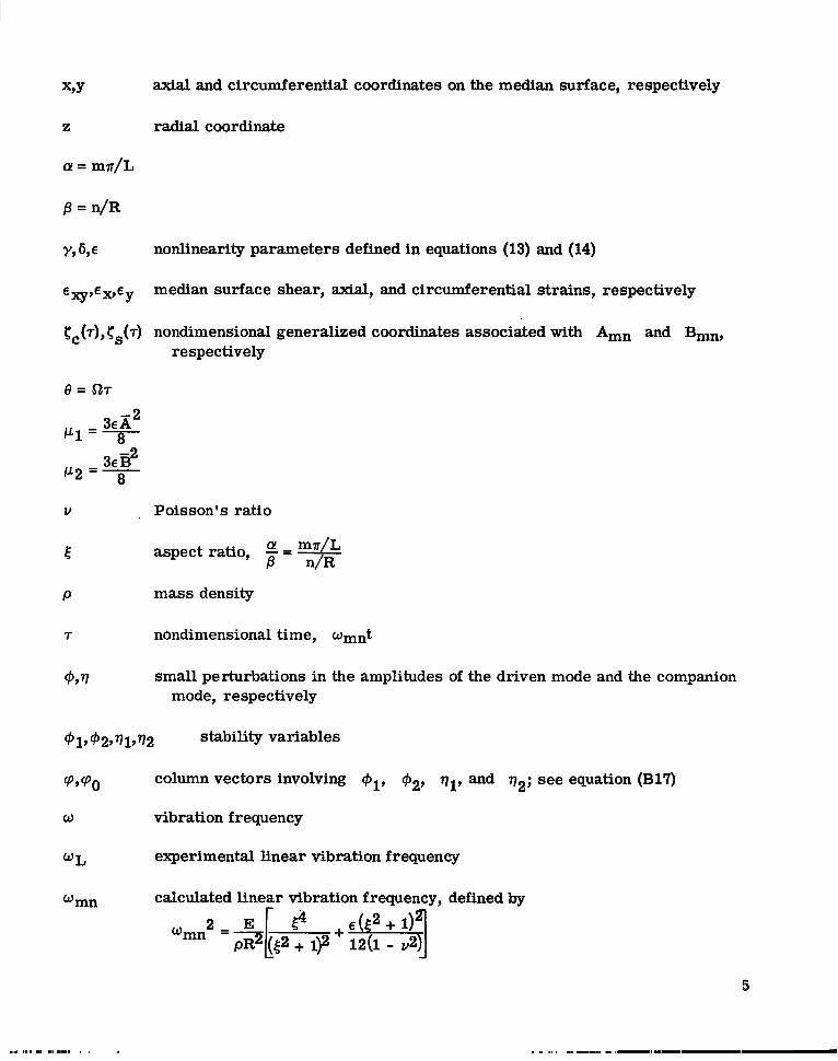
XYY axial and circumferential coordinates on the median surface, respectively
z radial coordinate
B = n/R
Y , O nonlinearity parameters defined in equations (13) and (14)
median surface shear, axial, and circumferential strains, respectivelyE ~ , E ~ , E ~
tC(r),CS(r) nondimensional generalized coordinates associated with Amn and Bmn, respectively
8 = 527
V Poisson’s ratio
5 aspect ratio, -= m?r/L B n/R
P mass density
7 nondimensional time, wmnt
9Y77 small perturbations in the amplitudes of the driven mode and the companion mode, respectively
91, 92,771,772 stability variables
W P O column vectors involving 92, ql, and q2; see equation (B17)
w vibration frequency
WL experimental linear vibration frequency
wmn calculated linear vibration frequency,defined by
A bar over a quantity indicates that it is an average value, where the average is taken over one period of the motion.
THEORY
The governing equations are first presented and briefly discussed. The problem is reduced to one involving ordinary differential equations by applying Galerkin's method. Approximate solutions for the nonlinear vibration of both a driven mode and its companion mode are obtained by the method of averaging. Stability of the response is also discussed.
Governing Equations
The well-known approximations of Dormell's shallow-shell theory for thin-walled circular cylinders as exemplified in reference 2 result in three equations of motion. These equations can be combined to give
and
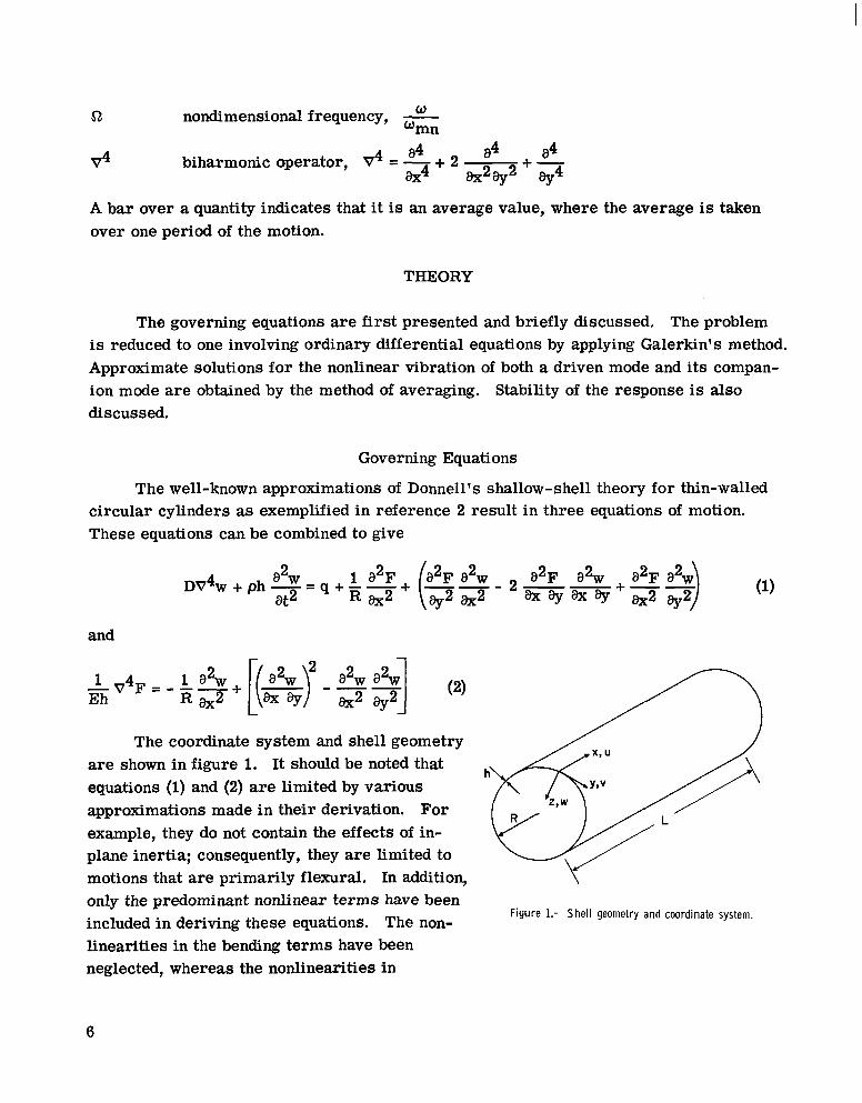
The coordinate system and shell geometry are shown in figure 1. It should be noted that equations (1) and (2) are limited by various approximations made in their derivation. For example, they do not contain the effects of in-plane inertia; consequently, they are limited to motions that are primarily flexural. In addition, only the predominant nonlinear terms have been included in deriving these equations. The non- Figure 1.- Shell geometry and coordinate system.
linearities in the bending terms have been neglected, whereas the nonlinearities in
6
stretching have been estimated by using the following midsurface strain-displacement relations:
Donnell’s approximation(:2 -e< 11has been used, and this assumption limits the analysis
to circumferential wave numbers greater than about 5. The usual thin-shell assumption,
<< 1, has been employed in the derivation, and transverse-shear and rotary-inertia(E)effects have been neglected.
The boundary conditions appropriate to equations (1) and (2) vary with the problem to be analyzed. However, for a complete cylindrical shell, such as is considered in the present problem, it is apparent that the displacements, slope, moments, shears, and stresses must all satisfy continuity conditions of the form
w(x,y,t) = W(X,Y+ (3)
v(x,y,t) = V(X,Y+ 2sR,t)
(Note that it is not sufficient that the stress function F be continuous and periodic in the y-variable.)
The preceding continuity requirements place a restriction on the choice of mode shapes which can be used in approximate analyses; the mode shapes are discussed in the following section.
Reduction to Ordinary Differential Equations
Equations (1) and (2) can be solved, approximately, by choosing a vibration mode for w, solving equation (2) to find F, and then using Galerkin’s method on equation (1). Throughout the calculations, w and F must be examined to verify that the necessary continuity requirements (eq. (3)) are met.
Choice of vibration modes.- For free vibrations of a freely supported cylinder, the linearized versions of equations (1)and (2) have the solution (ref. 2):
7
F(x,y,t) = fmn COS - COS wmntnY sin !?E R L
For nonlinear vibrations of a freely supported cylinder, a deflection of the form
w(x,y,t) = Amn(t)cos 9 sin - (5)mnx R L
was used in references 1to 3. However, as discussed in reference 5, equation (5) together with the corresponding stress function will not satisfy the necessary periodic continuity constraint on the circumferential displacement v. This difficulty is counteracted by replacing equation (5) with
nYW(X,y,t) = Amn(t)cos -R sin
where the term in the brackets is included to satisfy the continuity requirement on v (eq. (3)). Note that equation (6) gives w = 0 at the ends of the cylinder but the axial bending moment is not zero there.
Finally, previous studies on circular rings (ref. 8) and circular plates (ref. 9) have shown the necessity of including a companion mode in the nonlinear analysis. This additional mode has the same linear vibration frequency and the same (m,n) numbers as do the modes given in equations (4) to (6); hence, the term "companion mode" is used to describe it. When the companion mode is included, equation (6) becomes
Equation (7) represents the deflection modes assumed in the present report; these mode shapes are similar to those which apply to rings (ref. 8) and cylindrical shells of infinite length.
Application of Galerkin's method.- Before the Galerkin procedure can be applied, the stress function F must first be found. This function is determined by substituting the assumed deflection (eq. (7)) into equation (2) and solving for the particular solution. This procedure gives
F(x,y,t) = a1 (Amn COS j3y + Bmn sin By)sin @C
- a2(Amn2 - Bmn2)c0s 2j3y - a3AmnBmn sin 2m
+ a4(Amn2 + Bmn2)(Amn COS j3y + Bmn sin ,!@)sin~ C Y X
where CY = mr/L, p = n/R, and the coefficients a1 to a4 are defined in the section "Symbols."
8
At this stage in the analysis, w and F were examined to make certain that all the necessary continuity requirements were satisfied. (See appendix A for a further discussion of this point.) With w and F established as appropriate for a complete cylinder, equations (7) and (8) are substituted into equation (l), which is approximately satisfied by using Galerkin' s procedure. This procedure yields two coupled nonlinear differential equations for Amn(t) and Bmn(t). In nondimensional form, these equations are
and
where 5, and cs are vibration amplitudes, given by-
rs = -BmnJ h
and the dimensionless time T is defined by
T = Wmnt
where wmn is the linear vibration frequency.
The functions C ( T ) and S(T) in equations (9) represent the generalized forces on the two modes and are given by integral expressions involving q(x,y,t), %/aAmn, and %/8Bmn. The external loading q(x,y,t) is assumed to be fixed in space and harmonic in time, so that
q(x,y,t) = Q(X,Y)COSw t (11)
9
The function Q(x,y) is assumed to be symmetric with respect to y and to have zero average value. In this case S(T) is identically zero and
C(T) = Gmn COS 527 (12a)
where a=- w is a nondimensional frequency and the coefficient Gmn is given by wmn
L 2PR m m dxGmn = (LRP)ph2U,n2
s 0
s 0
Q(x,y)cos sin-dyL
Note that every nonlinear term in equations (9) contains the parameter E , which is defined by
Thus, E is the basic nonlinearity parameter in the problem; when E goes to zero the vibrations become linear. The other parameters which influence the nonlinearities are y and 6; they a r e defined by
In the derivation of equations (9), it should be noted that the weighting functions h/aAmn and k/aBmn have been used in the Galerkin procedure. This choice of weighting functions makes the resulting differential equations for Am, and Bmn equivalent to those obtained by using, the Rayleigh-Ritz method on this problem. (See ref. 10 in this regard.)
Furthermore, note that the specification of C(T) = Gmn cos st7 as the forcing function leads naturally to classifying the displacement associated with Amn(t) and cos 9 sin !.E?!as the driven mode. The companion mode is associated with Bmn(t)R L
ny sin -*and sin -R ",L and since S(7) = 0, the companion mode is not directly excited by the forcing function.
Approximate Solutions to the Nonlinear Equations
Inasmuch as C(T) and S(7) have been specified, equations (9) can be solved approximately by the method of averaging (ref. 11). Such solutions will be presented for vibrations involving (a) only the driven mode, and (b) both the driven mode and its companion mode.
Single-mode response.- Because S(7) = 0, a possible solution to equation (9b) is that fS(7) is identically zero. In this case, only rc(7) vibrates, and gives rise to the single-mode response. Using CS('r) = 0 and fC(7) = A(T)COSS ~ T in equations (9) and applying the method of averaging gives the approximate solution
where the average amplitude is computed from
5( l - s t 2 ) ~ - * s t 2 x 3 - y A- 3 +ZE6A =Gmn 16
for given values of E, Gmn, and the other quantities. A typical response curve of 1x1 as a function of 51 is given in figure 2 for E = 0.01 and 5 = 0.1. For purposes of comparison, E = 0.01 corresponds to n = 1Q and h/R = 0.001, and 5 = 0.1 corresponds to m = 1, n = 10, and L/R = 7r.
The solution for free vibrations involving DRIVEN MODE,
a single mode can be obtained from equation (17) by putting Gmn = 0. This solution gives the one-mode "backbone" curves shown in figures 3 and 4. These curves were computed from the expression
.88 .92 .96 1.00 1.04 1.08 FREQUENCY, A?,
and give the amplitude-frequency relation for Figure 2.- Single mode response. Forced and free vibrations,
free vibrations of a single mode. E = = 0.01, = n R / n - 0.1.L /m
11
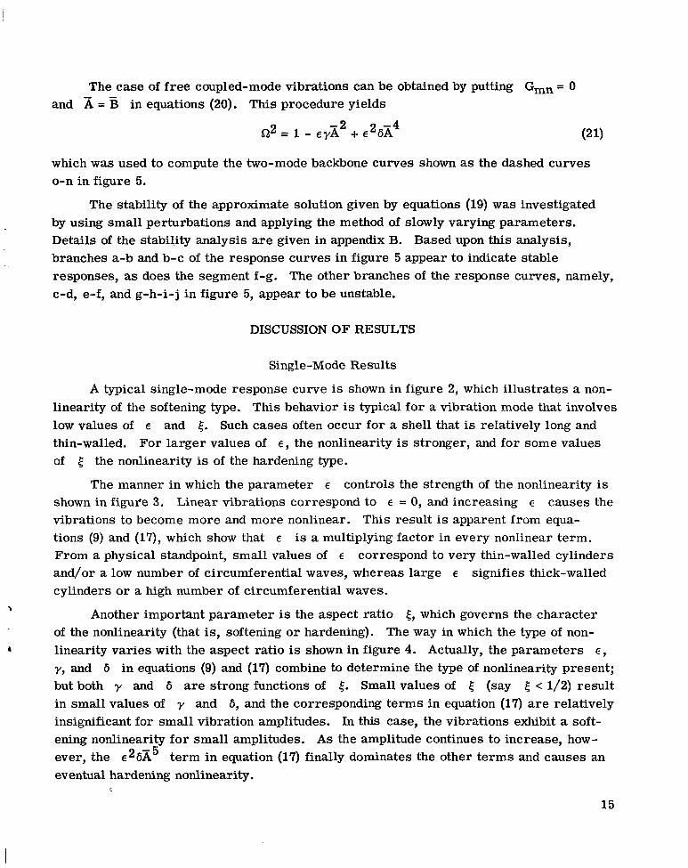
I I I I I .6 .8 I.o 1.2 1.4 1.6
FREQUENCY, i?, Figure 3.- Influence of large amplitudes on vibration frequency for various values of E. Free vibrations; one mode;
= 112 and 2; u = 0.3.
The stability of the approximate solution given by equation (16) was examined by the usual techniques of perturbation analysis, as described in appendix B. The resulting Mathieu-Hill stability equations (ref. 12) indicate that within terms of order e2:
(a) Perturbations of Cc are unstable within the area bounded by (eq. (B8)) -2
<n<1- 8 8
(b) Perturbations of fs are unstable within the region (eq. (B9)) -2
8
(c) Both types of perturbations are unstable in narrow regions near G? = 1/2, 1/3, . . .
The first instability region (a) coincides with the locus of vertical tangents to the response curves and indicates the well-known jump phenomena. The narrow areas (c)
12
AMPLITUDE,
AMPLITUDE, IzI
2.o
.8:::i.40 --if
I .2
0-.6 FREQUENCY,
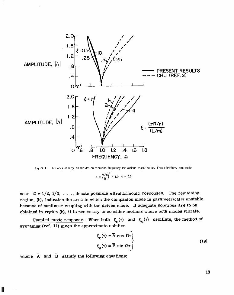
Figure 4.- Influence of large amplitudes on vibration frequency for various aspect ratios.
PRESENT RESULTS CHU (REF.2)
Free vibrations; one mode;
near 52 = 1/2, 1/3, . . .,denote possible ultraharmonic responses. The remaining region, (b), indicates the area in which the companion mode is parametrically unstable because of nonlinear coupling with the driven mode. If adequate solutions are to be obtained in region (b), it is necessary to consider motions where both modes vibrate.
Coupled-mode response.- When both rS(7) and rc(7) oscillate, the method of averaging (ref. 11) gives the approximate solution
Note that one possible solution to equations (20) is that = 0. In this case, equations (19) and (20a) revert to equations (16) and (17), respectively. Furthermore, inspection of equation (20b) reveals that real, nonzero values of B exist only if St satisfies the condition
which agrees with the preceding single-mode stability results, region (b).
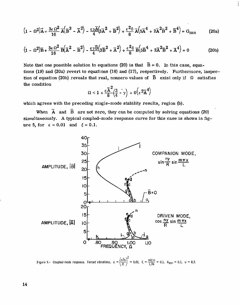
When and are not zero, they can be computed by solving equations (20) simultaneously. A typical coupled-mode response curve for this case is shown in figure 5, for E = 0.01 and 4 = 0.1.
AMPLITUDE, 1B1
I5- DRIVEN MODE, AMPLITUDE, 1x1 IO - cos”Y sin=
LR 5
h, I I
0 .80 .90 1.00 1.10 FREQUENCY, il,
Figure 5.- Coupled-mode response. Forced vibrations; E = = 0.1; G,, = 0.1; u = 0.3.
14
The case of free coupled-mode vibrations can be obtained by putting Gmn = 0 and A = in equations (20). This procedure yields
-2 2 -4Q2 = 1 - EYA + E 6A
which was used to compute the two-mode backbone curves shown as the dashed curves o-n in figure 5.
The stability of the approximate solution given by equations (19)was investigated by using small perturbations and applying the method of slowly varying parameters. Details of the stability analysis are given in appendix B. Based upon this analysis, branches a-b and b-c of the response curves in figure 5 appear to indicate stable responses, as does the segment f-g. The other branches of the response curves, namely, c-d, e-f, and g-h-i-j in figure 5, appear to be unstable.
DISCUSSION OF RESULTS
Single-Mode Results
A typical single-mode response curve is shown in figure 2, which illustrates a nonlinearity of the softening type. This behavior is typical for a vibration mode that involves low values of E and E,. Such cases often occur for a shell that is relatively long and thin-walled. For larger values of E , the nonlinearity is stronger, and for some values of E, the nonlinearity is of the hardening type.
The manner in which the parameter E controls the strength of the nonlinearity is shown in figul'e 3. Linear vibrations correspond to E = 0, and increasing E causes the vibrations to become more and more nonlinear. This result is apparent from equations (9)and (17), which show that E is a multiplying factor in every nonlinear term. From a physical standpoint, small values of E correspond to very thin-walled cylinders and/or a low number of circumferential waves, whereas large E signifies thick-walled cylinders or a high number of circumferential waves.
\ Another important parameter is the aspect ratio E,, which governs the character of the nonlinearity (that is, softening or hardening). The way in which the type of non-
I linearity varies with the aspect ratio is shown in figure 4. Actually, the parameters E,
y, and 6 in equations (9)and (17) combine to determine the type of nonlinearity present; but both y and 6 are strong functions of E,. Small values of 5 (say 5 < 1/2) result in small values of y and 6 , and the corresponding terms in equation (17) are relatively insignificant for small vibration amplitudes. In this case, the vibrations exhibit a softening nonlinearity for small amplitudes. As the amplitude continues to increase, however, the e26A5 term in equation (17) finally dominates the other terms and causes an eventual hardening nonlinearity.
15
For large values of 5 (say 5 > 2) the y and 6 terms in equation (17)dominate the nonlinearities immediately, and a corresponding hardening type of nonlinearity is observed for all amplitudes. The remaining area, where z < 5 < 2, represents a transition region in which the parameter y experiences a change in sign. Note that from its definition, small values of the aspect ratio 5 correspond to short circumferential and long axial wavelengths, whereas the reverse is true for large values of 5.
Of particular interest is the limiting case when the aspect ratio tends to zero. Such a case occurs when the length L tends to infinity. When free vibrations of a single mode are examined as L -c 03, both y and 6 vanish and equation (Sa) reduces to
This equation gives rise to a softening type nonlinearity and bears a strong resemblance to results obtained for inextensional nonlinear vibrations of rings (ref. 8).
For comparison purposes, Chu's results (ref. 2) have been plotted in figure 4. The theory of reference 2 indicates that the nonlinearity is always of the hardening type; similar results were obtained in references 3 and 4. It should be noted that the results of references 2 to 4 indicate a symmetric dependence on the aspect ratio 5, whereby the
1 1 1curves for 5 = -2, 8) . . . coincide with those for [ = 2, 4, 8, . . ., respectively. Such a symmetric dependence on the aspect ratio occurs for the nonlinear vibration of simply supported flat rectangular plates (ref. 13), as would be expected from the physical symmetry of the plate problem.
On the other hand, the problem of a thin-walled circular cylinder is physically nonsymmetric, since the cylinder is curved circumferentially but not axially. In the present problem then, it appears that the calculations should exhibit a nonsymmetric dependence on the aspect ratio 5. Such a nonsymmetric dependence on 5 is borne out by the results of the present analysis, as figure 4 shows.
Coupled-Mode Results LA plot of a typical response involving a driven mode and its companion mode is
shown in figure 5. The results are analogous to those obtained for nonlinear vibrations of rings (ref. 8) and for nonlinear vibration absorbers (ref. 14). Along the a-b portion of the curves (fig. 5), E is zero and only the driven mode responds. The segments b-c-d and e-f-g indicate vibrations in which both modes have comparable amplitudes; note that they are adjacent to the two-mode "backbone" curves, o-n. Along g-h-i-j, the response of the companion mode is much greater than that of the driven mode; note that the response of E as a function of SZ and the one-mode backbone curve (0-h-i-j) in
16
figure 5 then coincide. This result is analogous to the vibration-absorber response in which the driven mass experiences very little motion while the absorber mass vibrates with large displacements.
Points of vertical tangents to the response curves occur at c,f,g, and h, and the stability analysis indicates that the segments c-d, e-f, and g-h-i-j of the response curves are unstable. Instead of responding along the segment g-h-i-j, beyond the point g the vibrations apparently revert to the one-mode case, with B = 0 and x given by equation (17). In some cases, a gap in the solutions may occur, and then both the one-mode solution (eq. (16)) and the two-mode solution (eq. (19)) are unstable. Similar unstable gaps have been observed in related problems, and analog computer studies indicate that nonsteady vibrations with rapidly changing amplitudes occur in these regions. (For example, see refs. 8, 15, and 16 in this regard.)
Comparison With Available Experimental Results
Experimental results for the nonlinear flexural vibrations of thin-walled circular cylinders are rather scarce. Reference 6 gives nonlinear vibration data for cylinders both with and without an internal liquid. The results exhibit a softening type of nonlinearity, and for an empty cylinder the nonlinearity observed was very slight. Similar qualitative observations were reported in reference 5, and some recent quantitative results have been given by Olson, reference 7.
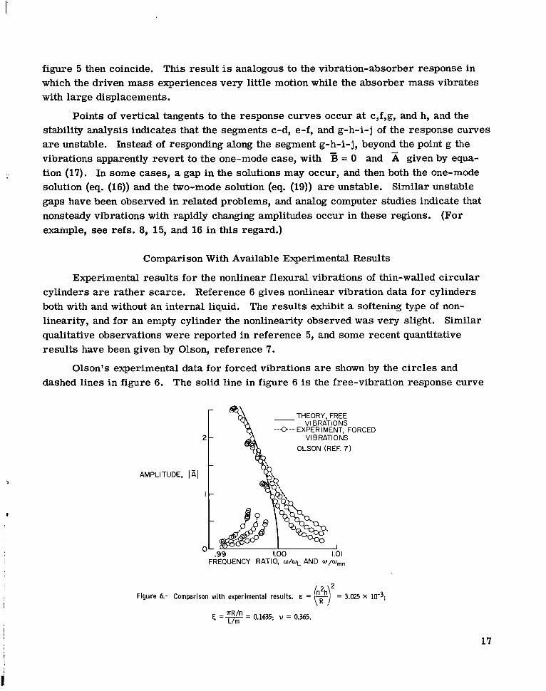
Olson's experimental data for forced vibrations are shown by the circles and dashed lines in figure 6. The solid line in figure 6 is the free-vibration response curve
THEORY, FREE - VIBRATIONS --e--EXPERIMENT, FORCED
VIBRATIONS OLSON (REF. 7)
AMPLITUDE,
FREQUENCY RATIO, W/WL AND W/wmn
Figure 6.- Comparison with experimental results. E = - = 3.025 X 10⁻³;
E, =%= 0.1635; i~ = 0.365.
17
-(cos
calculated from equation (18) with values of E , y, and 6 that correspond to Olson's experiment. Note that the experimental results are nondimensionalized with respect to the experimental linear frequency WL, whereas the analytical results are divided by the calculated frequency Wmn. Both theory and experiment indicate a nonlinearity of the softening type for this case, whereas the results of references 2 to 4 indicate a hardening type of nonlinearity for all cylinders.
Olson also detected a "double frequency contraction" at the nodes of cos 9R 'Because of the presence of the bracketed term in equation (6), the present analysis predicts such a double-frequency effect. For sufficiently large amplitudes, nonsteady vibrations were also observed (ref. 7); this behavior may have been due to the presence of the companion mode.
Vibrations involving both a driven mode and its companion mode have been found for ring vibrations, and traveling-wave responses can result (ref. 8). In the present case, the theory yields a traveling wave if the amplitudes and 5 are identical. When = B, the deflection becomes
h cos ~ i - nY + sin sin ?sin + n27i2 2or + sin2&)sin2 1 1 1 7 ~ ~cos -
R R 4R L
= cos(? - W7)sin - 2 - 2 sin2m m + -A L 4R
where the first term represents a circumferentially traveling wave. Traveling-wave responses have been observed in the vibration studies of reference 17 and in recent flutter tests on thin cylindrical shells (ref. 18).
CONCLUDING REMARKS
The nonlinear flexural vibrations of thin-walled circular cylinders were analyzed by choosing vibration modes and applying Galerkin's method. Although only one mode was directly driven by the forcing function, it was necessary to include two vibration modes in the calculations. Two modes were required because under certain conditions nonlinear coupling caused the companion mode to respond and participate in the motion. For other conditions, the single-mode response was sufficient. In both cases (single and coupled modes) the degree of nonlinearity is dependent upon wall-thickness- radius ratio and number of circumferential waves, and the type of nonlinearity is determined by the aspect ratio 4. Small values of 5 generally result in softening characteristics, and large values of 4 give rise to hardening effects.
t
18
c
The single-mode calculations are in qualitative agreement with the available test results, which indicate a slight nonlinearity of the softening type. Additional experiments are necessary to confirm the response of the companion mode and to examine the nonlinear behavior for larger values of 4. Measurements of the experimental vibration shape would also be worthwhile; the mode-shape data available to date are in substantial agreement with the radial deflection used in the analysis.
It should be noted that the present theory imposes no restraints on the axial in-plane displacements at the ends of the cylinder. Imposing the boundary condition that the axial displacement u = 0 at the cylinder ends might strongly alter the nonlinear behavior, especially for high values of 4 (that is, for "short" cylinders). In addition, it will be recalled that the present analysis loses accuracy for low values of the circumferential mode number n (for example, n < 5). This loss of accuracy is not expected to alter the qualitative behavior of the solutions, however.
Langley Research Center, National Aeronautics and Space Administration,
Langley Station, Hampton, Va., March 2, 1967, 124-08-0 5- 08-23.
,
19 !
APPENDIX A
DISCUSSION OF THE CONTINUITY REQUIREMENT
FOR THE CIRCUMFERENTIAL DISPLACEMENT
Since the cylindrical shell is assumed to be complete and circular, the displacements, slope, moments, shears, and s t resses must satisfy continuity requirements as noted in equation (3). In particular, the continuity requirement on the circumferential displacement v results in conditions which the functions w and F must satisfy. The purpose of this appendix is to derive and discuss these conditions for w and F.
The continuity requirement for v is given by
v(x,y,t) = ~(x ,y+2~R, t ) (A1)
This condition can be rewritten in the form
v(xYy+2nR,t)- v(x,y,t) = 0 = 1y+hR
$dyY
If an expression for h / a y is to be found in terms of w and F, it is necessary to examine the force-displacement relations. These relations are given by (see ref. 2)
Eliminating %/ax from these expressions and then solving for av/% gives
6
Substituting this expression for av/ay into the continuity condition given by equation (A2) results in the following relation between w and F:
Equation (A5) represents a condition on w and F which must be satisfied if the circumferential displacement v is to be continuous.
20
.I
APPENDIX A
When the expressions for w and F given in references 1 to 3 are substituted into equation (A5),the integral does not vanish. In other words, the functions for w and F given in these references will not satisfy the continuity requirement for the circumferential displacement v.
In order to satisfy the continuity requirement, it is necessary to modify w or F, o r both. For this reason, the deflection in the present report is chosen as given by equation (7). When w and F from equations (7) and (8) are substituted into equation (A5), the integral vanishes as required. Thus, the continuity condition for v is satisfied by the w and F givenin the present report.
. !
21
APPENDIX B
STABILITY ANALYSIS
The purpose of this appendix is to discuss the details of the stability calculations and to derive the stability boundaries previously discussed.
Stability of the Single-Mode Response
When only the driven mode responds, the response is given approximately by
As a test of the stability of the response, small-perturbation terms @ and r ]
are added to the approximate solution (Bl); that is, -
Cc(T) = A cos 517 +
Cs(d = 0 + r](4
Equations (B2) are substituted into equations (9) for Cc and 0,. The approximate solution given by equations (Bl) is assumed to satisfy equations (9) exactly, and the equations governing @ and r ] are therefore homogeneous. Only first-order terms in the perturbations a re retained, and the equations for @ and r ] become
and t
7
- (3~522-A2 -2 2 -4 2 x8 E yA ~ 2 ~ 6 252T E ~ 86A ) COS~ ~ ~
22
APPENDIX B
Equation (B3) is then simplified by the following transformations:
Let 8 = S ~ T , so that
Define pl = - and substitute for Cp:3EA2 8
e p1 sin28dB
+ p1 COS e
Then, equation (B3) yields
d2U+ pl COS2 e-+
)de2
3p1 a sin220
+plu=o2 2 1 This equation is further simplified by dividing by (1 + p1 cos2 0) and expanding the
denominator for small values of pl. Retaining only first-order terms namely, terms of order c x 2 ) gives
n
d'U-+ (M + 16K COS 2B)U = 0 d O2
where
Equation (B6) is now in the form of Mathieu's equation, which is discussed in detail by Stoker (ref. 12). The results of reference 12 are directly applicable to this analysis and can be used to determine approximate stability boundaries for the perturbation Cp(7).
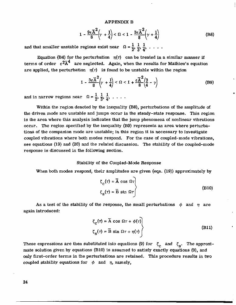
I The result of these calculations indicates that the perturbation Cp is unstable within the region given by
23
I
APPENDIX B
and that smaller unstable regions exist near 52 = -,-,1 1 1 2 3 4'""
Equation (B4)for the perturbation ~ ( 7 )can be treated in a similar manner if terms of order e2x4 are neglected. Again, when the results for Mathieu's equation are applied, the perturbation ~ ( 7 )is found to be unstable within the region
-2
8
1 1 1and in narrow regions near 52 = z' 5' . . . . Within the region denoted by the inequality (B8),perturbations of the amplitude of
the driven mode are unstable and jumps occur in the steady-state response. This region is the area where this analysis indicates that the jump phenomena of nonlinear vibrations occur. The region specified by the inequality (B9)represents an area where perturbations of the companion mode are unstable; in this region it is necessary to investigate coupled vibrations where both modes respond. For the case of coupled-mode vibrations, see equations (19)and (20)and the related discussion. The stability of the coupled-mode response is discussed in the following section.
Stability of the Coupled-Mode Response
When both modes respond, their amplitudes are given (eqs. (19))approximately by
Cc(7) = iicos 52.7
-cs(7) = B sin 527J
A s a test of the stability of the response, the small perturbations 6 and 7 are again introduced: <
Cc(7) = COS 527 4-@(7)
-ts(r)= B sin 527 + q ( ~ )1
These expressions are then substituted into equations (9)for Cc and Cs. The approximate solution given by equations (B10)is assumed to satisfy exactly equations (9), and only first-order terms in the perturbations are retained. This procedure results in two coupled stability equations for @ and ?,I,namely,
24
-- --
--
APPENDIX B
- ~ y ( 3 ~ ~ c o s ~ O + 6A-2-2+ B2sin2e)+ ~ ~ 6 ( 5 x ~ c o s ~ eB sin2O cos2e + B4cos4e] cp
3e 3E 2-+ g x B s i n e c o s eQ+-S2xEcos28$- k ( S 2 A B s i n O c o s 0) 8 d?? 4
and
- 2 2 ) 2 (-4 -2-2- Ey(x2cos20 + 3B sin 8 + E 6 A cos 4 8 + 6A B sin2e cos'e + 5B4sin48)l q
+-ABsin Ocos e- -qQABsin 2 e-+3e 3E :$ [FQ ~ A Bsin e cos e 8 d?
+ EYE sin 2e - 2E 26AB sin 2e(x2cOs e + B2sin2e)l + = 0
where the substitutions
e = QT
PI=- 3EX2 8
3E B2p2=- 8
have been used to simplify the results. ,
Equations (B12) and (B13) are coupled equations with periodic coefficients, and exact solutions to them are not known. However, approximate results for the stability boundaries of these equations can be obtained by using the method of slowly varying parameters (ref. 19).
25
APPENDIX B
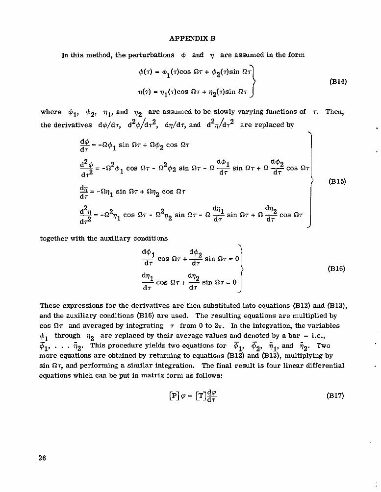
In this method, the perturbations @ and q are assumed in the form
@(r)= @l(r)cos5127 + r#12(r)sin 0314)
q(r)= ql(r)cos 517 + q2(r)sin 517
where @2, ql, and q2 are assumed to be slowly varying functions of r. Then,
the derivatives d@/dr, d2@/d?, dq/dr, and d2q/dr2 are replaced by
9= sin or + cos 517d r
2 d@l d@2!A = -&pl cos 517 - 512 $2 sin 527 - 51 -d r sin 517 + 51 -d r cos 51r
d? I (B15)d3= -nql sin + nq2 cos 517d r
2 dql dq29= -$ql cos 517 - n2q2sin 517 - 51 -sin 07 + 51 -cos 517d? d r d r J
together with the auxiliary conditions \
d@l d@2-d r cos 517- + -d r sin 517 = 0
dql cos 51r + - dq2 sin 517 = 0 d r d r I
These expressions for the derivatives a re then substituted into equations (B12)and (B13), and the auxiliary conditions (B16)are used. The resulting equations a re multiplied by cos 517 and averaged by integrating r from 0 to 27r. In the integration, the variables
@1 through q2 are replaced by their average values and denoted by a bar - i.e., ql, . . . i2.This procedure yields two equations for Fl, F2, Gl, and t2. Two more equations are obtained by returning to equations (B12)and (B13),multiplying by sin 517, and performing a similar integration. The final result is four linear differential equations which can be put in matrix form as follows:
26
APPENDIX B
where
r p =
and the matrices [PI and [T] contain elements that are constants which depend upon-the steady-state solution through the values of x, B, 52, E, y, and 6.
Equation (B17)is solved by using rp = rpoeAT and leads to an eigenvalue problem for the A:
IP-AT1 = O ( B W
The matrices [PI and [TI are nonsymmetric, and equation (B18)yields complex roots. If any of the roots have a positive real part, then the corresponding perturbations increase exponentially with time. In this case, the associated steady-state solution is said to be unstable; conversely, if none of the roots of equation (B18)has a positive real part, the solution is said to be stable.
Stability of the steady-state solution given by equation (B10)was investigated by-substituting representative values of A, B, and 52 into equation (B18)along with the associated parameters E , y, and 6 . For each case, the roots were examined to determine whether or not they had a positive real part. In this manner, the stability of the solution plotted in figure 5 was determined; the results of the calculations a re discussed in the main text.
27
I
REFERENCES
1. Reissner, Eric: Non-Linear Effects in the Vibrations of Cylindrical Shells. Rept. No, AM 5-6, Guided Missile Res. Div., The Ramo-Wooldridge Corp., Sept. 30, 1955.
2. Chu, Hu-Nan: Influence of Large Amplitudes on Flexural Vibrations of a Thin Circular Cylindrical Shell. J. Aerospace Sci., vol. 28, no. 8, Aug. 1961, pp. 602-609.
3. Cummings, Benjamin E.: Some Nonlinear Vibration and Response Problems of Cylindrical Panels and Shells. SM 62-32 (AFOSR 3123) Graduate Aeron. Labs., Calif. Inst. Technol., June 1962.
4. Nowinski, J. L.: Nonlinear Transverse Vibrations of Orthotropic Cylindrical Shells. AIAA J., vol. 1, no. 3, Mar. 1963, pp. 617-620.
5. Evensen, David A.: Some Observations on the Nonlinear Vibration of Thin Cylindrical Shells. AIAA J. (Tech. Notes and Comments), vol. 1, no. 12, Dec. 1963, pp. 2857-2858.
6. Kana, Daniel D.;Lindholm, Ulric S.; and Abramson, H. Norman: An Experimental Study of Liquid Instability in a Vibrating Elastic Tank. J. Spacecraft Rockets, vol. 3, no. 8, Aug. 1966, pp. 1183-1188.
7. Olson, Mervyn D.: Some Experimental Observations on the Nonlinear Vibration of Cylindrical Shells. ALAA J. (Tech. Notes), vol. 3, no. 9, Sept. 1965, pp. 1775-1777.
8. Evensen, David A.: A Theoretical and Experimental Study of the Nonlinear Flexural Vibrations of Thin Circular Rings. NASA TR R-227, 1965.
9. Tobias, S. A.: Non-Linear Forced Vibrations of Circular Discs. Engineering, vol. 186, no. 4818, July 11, 1958, pp. 51-56.
10. Singer, Josef: On the Equivalence of the Galerkin and Rayleigh-Ritz Methods. J. Roy. Aeron. SOC.,vol. 66, no. 621, Sept. 1962, p. 592.
11. Bogoliubov, N. N.; and Mitropolsky, Y.A.: Asymptotic Methods in the Theory of Non-Linear Oscillations. Gordon & Breach Sci. Publ., Inc., 1961.
12. Stoker, J. J.: Nonlinear Vibrations in Mechanical and Electrical Systems. Interscience Publ., Inc., c.1950.
13. Herrmann, George: Influence of Large Amplitudes on Flexural Motions of Elastic Plates. NACA TN 3578, 1956.
14. Arnold, F.R.: Steady-State Behavior of Systems Provided With Nonlinear Dynamic Vibration Absorbers. J. Appl. Mech., vol. 22, no. 4, Dec. 1955, pp. 487-492.
28
I
15. Miles, John W.: Stability of Forced Oscillations of a Spherical Pendulum. Quart. Appl. Math., vol. XX,no. 1, Apr. 1962,pp. 21-32.
16.Hutton, R.E.: An Investigation of Resonant, Nonlinear, Nonplanar Free Surface Oscillations of a Fluid. NASA TN D-1870, 1963.
17.Mixson, John S.; and Herr, Robert W.: An Investigation of the Vibration Characteristics of Pressurized Thin-Walled Circular Cylinders Partly Filled with Liquid. NASA TR R-145, 1962.
i 18. Olson, Mervyn D.;and Fung, Y.C.: Supersonic Flutter of Circular Cylindrical f
Shells Subjected to Internal Pressure and Axial Compression. AIAA J., vol. 4, 8 no. 5, May 1966,pp. 858-864.
19. McLachlan, N. W.: Ordinary Non-Linear Differential Equations in Engineering and Physical Sciences. Second ed., The Clarendon Press (Odord), 1956.
I,'
!
NASA-Langley, 1967 -32 L-4658 29
1.
r
“The aeronautical and space activities of the United States shall be conducted so as to contribute . . . to the expansion of human knowledge of phenomena in the atmosphere and space. The Administration shall provide for the widest practicable and appropriate dissemination of information concerning its activities and the results thereof.”
-NATIONAL AERONAUTICS AND SPACE ACT OF 1958
NASA SCIENTIFIC AND TECHNICAL PUBLICATIONS
TECHNICAL REPORTS: Scientific and technical information considered important, complete, and a lasting contribution to existing knowle&e.
TECHNICAL NOTES: Information less broad in scope but nevertheless of importance as a contribution to existing knowledge.
TECHNICAL MEMORANDUMS: Information receiving limited distributionbecause of preliminary data, security classification,or other reasons.
CONTRACTOR REPORTS: Scientific and technical information generated under a NASA contract or grant and considered an important contribution to existing knowledge.
TECHNICAL TRANSLATIONS: Information published in a foreign language considered to merit NASA distribution in English.
SPECIAL PUBLICATIONS: Information derived from or of value to NASA activities. Publications include conference proceedings, monographs, data compilations, handbooks, sourcebooks, and special bibliographies.
TECHNOLOGY UTILIZATION PUBLICATIONS: Information on technology used by NASA that may be of particular interest in commercial and other non-aerospace applications. Publications include Tech Briefs, Technology Utilization Reports and Notes, and Technology Surveys.
Details on the availability of these publications may be obtained from:
SCIENTIFIC AND TECHNICAL INFORMATION DIVISION
NAT10NA L A ER 0NA UTICS A ND SPACE AD MI NISTR AT ION Washington, D.C. PO546