Page 1
W..e_: NASA Technical Memorandum 4628
Recommended Techniques for Effective
Maintainability
A Continuous Improvement Initiative of the NASA Reliability and
Maintainability Steering Committee
December 1994
=
|
w
(NASA-TM-4628) RECOMMENOEO
TECHNIQUES FOR EFFECTIVE
MAINTAINABILITY. A CONTINUOUS
IMPROVEMENT INITIATIVE OF THE NASA
RELIABILITY AND MAINTAINABILITY
STEERING COMMITTEE (NASA) 105 p
#
\
N95-31530
Unclas
H1/38 0060399
Page 2
= J
J
Ira!
J]
ii
U
mmm
mini
mJ
r -
w
J
_JW
IL
u
h_
Page 3
. ,w
rw
n
__°
w
w
w
w
w
PREFACE
Current and future NASA programs face the challenge of achieving a high degree of mission
success with a minimum degree of technical risk. Although technical risk has several
elements, such as safety, reliability, and performance, a proven track record of overall system
effectiveness ultimately will be the NASA benchmark. This will foster the accomplishment of
mission objectives within cost and schedule expectations without compromising safety or
program risk. A key CharaCteristic of systems effeci_veness is the impiementation of
appropriate levels of maintainability throughout the program life cycle.
Maintainability is a process for assuring the ease by which a system can be restored to
operation following a failure. It is an essential consideration for any program requiring ground
and/or on-orbit maintenance. TheiOffice of S_._ty"and Mission Assurance (OSMA) has
undertaken a continuous improvement initiative to develop a technical roadmap that will
provide a path toward achieving the desired degree of maintainability while realizing cost and
schedule benefits. Although early life cycle costs are a characteristic of any assurance
program, operational cost savings and improved system availability almost always result from
a properlY administered maintainability assurance program. Past experience on NASA
programs has demonstrated the value of an effective maintainability program initiated early in
the program life cycle.
This memorandum provides guidance towards continuous improvement of the life cycle
development process within NASA. It has been developed from NASA, Department of
Defense, and industry experience. The degree to which these proven techniques should be
imposed resides with the project/program, and will require an objective evaluation of the
applicability of each technique. However, each applicable suggestion not implemented may
represent an increase in program risk. Also, the information presented is consistent with
OSMA policy, which advocates an Integrated Product Team (IPT) approach for NASA
systems acquisition. Therefore, this memorandum should be used to communicate technical
knowledge that will promote proven maintainability design and implementation methods
resulting in the highest possible degree of mission success while balancing cost effectiveness
and programmatic risk.
Frederick D. GregoryAssociate Administrator for
Safety and Mission Assurance
w
Page 4
DEVELOPING ACTIVITY
The development of this technical memorandum has been overseen by the NASA Reliability and
Maintainability (R&M) Steering Committee, which consists of senior technical representatives
from NASA Headquarters and participating NASA field installations. This Committee exists to
provide recommendations for the continuous improvement of the R&M discipline within the
NASA community, and this manual represents the best technical "advice" on designing and
operating maintainable systems from the participating Centers and the Committee. Each
technique presented in this memorandum has been reviewed and approved by the Committee.
CENTER CONTACTS
Appreciation is expressed for the dedication, time, and technical contributions of the following
individuals in the preparation of thismanual. Without the support of their individual Centers,
and their enthusiastic personal support and willingness to serve on the NASA R&M Steering
c-bmmittee, the capture oftlie m_inffinab_tytechniques _ofi/a_ned in this manual would not be
possible. -"
All of the NASA Centers are invited to participate in this activity and contribute to this manual.
The Committee members listed below may be contacted for more information pertaining to these
maintainability techniques.
Mr. Donald Bush
George C. Marshall Space Flight Center
CR85 Bldg 4203
Marshall Space Flight Center, Alabama 35812
Mr. Vincent Lalli
Lewis Research Center
MS 501-4 Code 0152
21000 Brookpark Road
Cleveland, Ohio 44135
Mr. Malcolm Himel
Lyndon B. Johnson Space Center
Bldg. 45 RM 618A, Code NB2
Houston, Texas 77058
Mr. Leon Migdalski
John F. Kennedy Space Center
RT-SRD-2 KSC HQS 3548
Kennedy Space Center, Florida 32899
Mr. Ronald Lisk
NASA Headquarters Code QS
200 E Street, SW
Washington, DC 20546
w
U
m
mJ
m
M
U
R
i
m
I
B
g
u
m
w
J
ii U
mI
Page 5
. J
w
w
w
22w
TABLE OF CONTENTS
SECTION PAGENUMBER
PREFACE ................................................................ i
DEVELOPING ACTIVITY .................................................. ii
CENTER CONTACTS ...................................................... ii
I. INTRODUCTION ...................................................... v
II.
A. Purpose .......................................................... v
B. Control/Contributions ............................................... v
C. Maintainability Technique Format Summary ........................... vi
RECOMMENDED TECHNIQUES FOR EFFECTIVE MAINTAINABILITY
Program Management
Technique PM-I : The Benefits of Implementing Maqntainability on NASA Programs .... PM-2
Technique PM-2 : Maintainability Program Management Considerations ............. PM-8
Technique PM-3: Maintenance Concept for Space Systems ....................... PM-14
Design Factors and Engineering
Technique DFE-I : Selection of Robotically Compatible Fasteners and
Handling Mechanisms .................................... DFE-2
Technique DFE-2: False Alarm Mitigation ................................... DFE-8
Analysis and Test
Technique A T-l: Neutral Buoyancy Simulation of On-Orbit Maintenance ............ AT-2
Technique A T-2: Mean Time To Repair Predictions ............................. AT-7
Technique A T-3: Availability Prediction and Analysis ........................... AT-12
Technique A 7-4: Availability, Cost, and Resource Allocation (ACARA) Model
to Support Maintenance Requirements ......................... AT- 17
Technique AT-5: Rocket Engine Failure Detection Using an Average Signal
Power Technique ......................................... AT-21
Operations and Operational Design Considerations
Technique OPS-I : SRB Maintainability and Refurbishment Practices ............... OPS-2
Technique OPS-2: Electrical Connector Protection ............................. OPS-9
Technique OPS-3: Robotic Removal and Application of SRB Thermal Systems ....... OPS- 11
Technique OPS-4: GHe Purging of H 2 Systems ............................... OPS- 17
Technique OPS-5: Programmable Logic Controller ........................... OPS-20
III
Page 6
TABLE OF CONTENTS (CONT.)
SECTION: PAGE NUMBER
Operations and Operational Design Considerations (cont.)
Technique OPS-6: DC Drive - Solid State Controls ............................ OPS-24
Technique OPS-7: AC- Variable Frequency Drive Systems ..................... OPS-28
Technique OPS-8: Fiber Optic Systems ..................................... OPS-32
Technique OPS-9: Pneumatic Systems-Dome Loaded Pressure Regulator Loading .... OPS-36
Technique OPS-IO: Modular Automatic Power Source Switching Device OPS-39
Technique OPS-11: Pneumatic System Contamination Protection ................. OPS-42
m. APPENDIX A: CANDIDATE TECHNIQUES FOR
FUTURE DEVELOPMENT ............................................ A-1
m
IBm
m
im
I
m
m
g
I
M
il
IB
J
m_
w
E
mw
u
I
1v
m
u
Page 7
w
r
w
? f
w
L_
w
W
w
L .
I. INTRODUCTION
A. PURPOSE
Maintainability is a process for assuring the ease by which a system can be restored to
operation following a failure. Designing and operating cost effective, maintainable systems
(both on-orbit and on the ground) has become a necessity within NASA. In addition, NASA
cannot afford to lose public support by designing less than successful projects. In this era of
shrinking budgets, the temptation to reduce up front costs rather than consider total program
life cycle costs should be avoided. In the past, relaxation of R&M requirements to reduce up
front costs has resulted in end-items that did not perform as advertised and could not be
properly maintained in a cost effective manner. Additional costs result when attempts are
made late in the design phase to correct for the early relaxation of requirements.
The purpose of this manual is to present a series of recommended techniques that can
increase overall operational effectiveness of both flight- and ground-based NASA systems.
Although each technique contains useful information, none should be interpreted as a
requirement. The objective is to provide a set of tools to minimize the risk associated with:
• Restoring failed functions (both ground and flight based)
• Conducting complex and highly visible maintenance operations
• Sustaining a technical capability to support the NASA mission utilizing aging equipmentor facilities.
This document provides (1) program management considerations - key elements of an effective
maintainability effort; (2) design and development considerations; (3) analysis and test
considerations - quantitative and qualitative analysis processes and testing techniques; and (4)
operations and operational design considerations that address NASA field experience. Updates
will include a section applicable to on-orbit maintenance with practical experience from NASA
EVA maintenance operations (including ground and on-orbit operations and ground-based
simulations). This document is a valuable resource for continuous improvement ideas in
executing the systems development process in accordance with the NASA "better, faster,
smaller, and cheaper" goal without compromising mission safety.
B. CONTROL/CONTRIBU_ONS
This document will be revised periodically to add-new techniques or revisions to the existing
techniques as additional technical data becomes available. Contributions from aerospace
contractors and NASA Field Installations are encofir_/ged. Any technique based on
project/program experience that appears appropriate for inclusionin this manual should be
submitted for review. Submissions should be fo _n-nattedid_entical!y to the techniques in thismemorandum (Figure 1) and sent to the address below for consideration.
National Aeronautics and Space Administration
Code QS
300 E Street S.W.
Washington, DC 20546
V
Page 8
Organizations submitting techniques that are selected for inclusion in this manual will berecognized on the lower portion of the first page of the published item. Contacts listed earlier in
this document should be used for assistance. If additional information on any technique isdesired, the contacts listed earlier in this document can be utilized for assistance.
C. MAINTAINABILITY TECHNIQUE FORMAT SUMMARY
The maintainability techniques included in this manual are Center-specific descriptions ofprocesses that contribute to maintainability design, test, analysis and/or operations. Eachtechnique follows a specific format so users can easily extract necessary information. The firstpage of each technique is a summary of the information contained, and the rest of the techniquecontains the specific detail of the process. Figure 1 shows the baseline format that has been usedto develop each technique.
W
D
D
I
=_
g
B
Technique Title, page numbeJ
Technique XXX-._ *_
TECHNIQUE FORMAT
Techniaue: A brief statement defining the design technique and how it is used.
Benefits: A concise statement of the technical improvement and�or impact on resource expenditurerealized from implementing the technique.
Key Words: Any term that captures the theme of the technique or provides insight into the scope.
Utilized for document search purposes.
Application Experience: Identifiable programs or projects that have applied the technique within NASA
and/or industry.
Technical Rationale: A brief technical justification for the use of the technique.
Contact Center: Source of additional information, usually sponsoring NASA Center.
Techniaue Description: A technical discussion that is intended to give the details of the process. The
information should be sufficient to understand how the technique should be implemented.
References: Publications that contain additional information about the technique.
'* Each technique within a section is identified using one of the following acronyms specific to that section'ollowed by the associated sequential technique number.
• PM: Program Management
• DFE: Design Factors and Engineering• AT: Analysis and Test
• OPS: Operations and Operational Design Considerations
m
IB
m
J
BB
U
w
m
m
Figure 1: Technique Format Definitionsw
!
vi!
I
Page 9
w
w
w
Program Management
w
A fundamental key to program and mission success is the development of systems that are reliable
and affordable to operate and maintain with today's limited resources. Early definition of both
hardware and software requirements that provide the capability for rapid restoration when failures
occur is essential. While incorporation of a maintainability program may require some additional
early investment, the resulting benefits will include operational cost savings and improved system
availability. The techniques included in this section are intended to provide management personnel
with an understanding of all information necessary to develop, foster, and integrate a successful
maintainability program that will enhance mission success and lower overall costs. Each technique
provides high-level information on a specific subject, and can be tailored or expanded to achieve
optimum application.
W
Page PM- 1
Page 10
W
I
m
l
I
U
m
imii
mm
II
z
RmD
m
I
IB
mWi
D
m
L_
Im
w
g
mm
II
Page 11
The Benefits of Impleraenting Maintainability on NASA Programs, Page I
Technique PM-I
t
_ T
_5
_z_r
r _
Technique Programmatic provisions for ease of maintenance greatly enhance
hardware and software system operational effectiveness for both in-
space and ground support systems.
':i:i:_::i:-:_:i_:iiii_:_-_.i:ii:._:_!_i_-..:'_'_!_?.i_i:_?_:i_-ii.:i?ii_i:!__'i_i:_i_i_:,.'.:i:'_-'._.:.:_.:'_ii!_i:_:._!_:_:_;_:..`._._..:_!._!_!_._;_._¢._.:_i_k_.!!_:_.iiii:.:_#.`:.._..:::_!::._!._.:_`:_.:._::i_:::_:_!_i:.::_..`._.`:._?:i!_.`..:_:_.`..:_:!:_.`.:_`.._!_..:_:._:._?.`.._i_i.`_.`..i_i_i.:_i_i_ii._._._f_!:..':_._._!:i::.!._:_
._'!i_'::!::!_i_::_:'._..;._..`._:_.:_4._...._.._!_..``_`:_i..`.:.._?.;_.:_:i_:_._:_ii_.__:._._:_i:i:?.i_:::_:_:!:i:i:_:is_i_a_:_._._._..:_:`:_'.._.k:[_?;._._:_.:`.:_:_`::::.':_:_:_:_:_::::_:!:i_i_:_:_:_:_i:i_:_:_g:_:_::::.:_:_:._,'._,'-_:.'.*'.::_i:_-:::_._::_.'."::_.'.':?-!._:i:!_-::.'._:_ __;i:'_ ___-.'-__-'.:_:_:_:'.:::_:_:m::-:::-'."i.:_i_i:-.:_iiii_i_:,:_:?'.;._i_._..,.!_!_!_._!-_:"_ ..`::_:_:_:i.`:.:¢_:_:_i::<i:?..::_t_¢:._.!_.::_::_::`::_;g_:!.:_:i:i_:i_:i:i:i:_:_:_:_:._:._.:::._:.:_:i:_.:_:i:_:_.x._z._:_..._:_!:_!__'::.:_:i:_-'::__i:_;'.": ":",_._i_:__'_;_......... ===============================================.... _i,__
e_)_ __._.::_._i_._i_``_`!_.:.._._'.:_:_.`_:::_`:_::.`:::_:::.:::_:_:_::_:_:_:_:_::*_:._:::::::::::::::::::::::::::::::::::::::::::::::::::::::::::::.................¢::_,:_:_:_,:.,.,...:_:._:::._::.,:::::.:_,:::.,_,.:..,,: :,,:,.,,,_ _ .-..,...... .?.......... _:,_::':':_".,.'_:_!_............._.:_i!i_:.:!!_!._:.:.:.::_!.:.._.....`!.:..``....`.._....:._.:.:......`_...._?.¢.:_..`:!_.:...._i_...._:...::_....:.`:_..._._:_;_......_...:_i!_........:._......:._..........:'.:"i_'"'"_:_:'_ _: i" !_!
: :_:$'..'::.:::."::_:_'._. : _:..:.:-_:::¢':':":':'_.$':::::::::::':,:::::::::::_.::_.:::::.':::::5::.":::: :'2:..:....,..'.'_.::U.'¢ ._ _._...-:..:4.:...>'..:_.-.-.:-.-:, _:`::.:....:.:._:.:_.::.:.:_.+:.`_:.::::::::._._:.:_..:_:_:.:._:._:+_+::.._:._:.:_:¢_:.:_:_._......_:_.:_.+_._ _::-...:---:--c.,._.-.:.:::..::.'- -%:$ -. ,::::::::::::::::::::::::::::: _:::".:::_:.'.:_:_%".::_:"<:_-:_.:_-'.:_.:.'.:::::::::::::::::::::::: :::: _.'.<-'.':?.!:!::E:._'_-'.:!:i_:_.'.:E_:_.'.':_!::$i:i:i:i:.::i:i:_::_:_:!:_:.'.:i:_:: :i:_::::._::: :.::i:'_:_:_kq_:_::_ _:_'_._ i:: _.
::'".':._::::-:":::::'_:_:::::_!!:'.' ,'-:::_:._:_:_::_:':::-5:_.::_:'..::_:':_:_:_:_:$:::_ :.:_<._.:._:.:+:_:+:.:.:.:_:.:.._`...:_:.:.:._<_:+:.::;:<.:._:_2:_..:.:_:::::::_::::..<_:.:._:.:.a:.:_.x.:.:.:.:.x_:<.:<.:.:_`:.:.:.:.:._:+:.:_:.:.:.:_:.:.:_._:_..:._<:`+:_:.:_:.:_:._:.:+:.:.:.:.:_.._:::._:::.._..:_ ::-':::_::+':::-:-'_.:_'...'_..:,,:,-.:?.::_,.:.._::_.,..<:_,:._-_::_::_.,,-.._:,,._::::,::._:.:.:_.:.,,:..,_,,.._:.:.:.:....:.:.:.:.:,.:,,,..,:._!:.....!_!i!_.:_._.i_.i.:.:`:ii_i_.i._r..i...:_:_:_..`::._.._:._!_!_:.._.:_._...>:_!_._.`:_i_._:_ii`_!_!_!_:_i_i_i_i:i_;_!_!_i_!_:_ii!_:_i_:'::: _._ _.i__.".:_::_:_'-':_¢_!_. :._:-_:_::_:_-':_-::::-:-:-:-:-:-.'--'-':,':':'.::.......... ,__'.-":::*.'.':':'_::>:::_:.-:::_::::.":."-":_.".".:"::'::_:..'-_::i-:'_:::.,::_:_#:.-"_:_:'i_/..:!::::i:_:_:_._:_."_':i:_..':.":::;::::'.-:!:_-:.':#_:_'._::'::?.::::!::::';'.:._.__':':_.!_'_.i_i.:i;_.".::._i_.:ii-'!_ii_i!i:,:i:_:_ii:_._:-._:".<._?:i_._!!-:::'.:,__:_ _ii!
::::::::::::::::::::::::::::::::::::::::':.::_::_!:::?._:_?-_:'_'_::':_::::-5:_::-::_:..:_:$:_.:::'_,'.:.::::_.:._::::.::::::'¥.'..:::.::::::::::.:_:.:.:-:..:,:.:.tt::.2-'.:.'-....".........:.:..:-:-::.'+:.:.':*:-:...:.....,-.........-..-,...........:.-...--.--'.-------.----'--.--:.:.-_'.-".'-<-.":-'.'.'..'.'.:.'-'--<<.<-_.-:-+_:.:.::_'-':_:'-'_$.::!:!:::::_:_:::::::::::-.::?.::?.::.:_:_:::......... .... .... _: -.. ::..
:_ t-_i__#ii_..'..'_::_ _._i?..'_i_'.._:_i_-;._i.'::_._;..!._._i;..._i_::::::::::::::::::::::::::::::::::::::::::::::::::::::::::::::::::::::::::::::::- ._.:_:._:_._<_._:_:_!:!:_.....`_:::._::_:_._.`::_.._.`..:i.`..:!:!::.._:_:_i_._::i::__:''_:::_:-_';":-_:_:_:_-:'._; :.__g__i:_:"_'.._?.._:.-':!'!i_'iii_i'i:':?._ii-i-_i'_!_.:'.f.__ :_"-i_i.::_:!__:._::_: :__?:.!_:_,.'.:_:_:i:?_;:.,'_.__'..__'_:'__: :_::._._:-_ :_.,.'::_!_i::_E'i_i:'...'.'i:i_-::_!.'.._?.":_'?.':_::g!::::: :_._(<__:.::_.'..:_::-_-":_!:'-:':i._
:_ ...::_:::_::::'-:.:-:_:_::-:::::.:.:.:.:-_ ::::::::::::::::::::::::::::::::::::::::::: :_::_..::::_:::::::::::::::::::::::::::::::::::::::::::::::::::::::::::::::::::::::::::::::::::::::::::::::::::::::::::::::::::::::::::::::::::::::::::::::::::::::::::::::::::::::::::::::::::::::::::::::::::::::::::::::::::::: :-:::::::::::::::::_
_._:: _: :::x 4_: :::._:: _.:::_.:: _:._ _: _ ._: .'.:.'._: ::::::::::::::::::::::.<::??:i_::_..:_.::_!?-_:.::_:.::_:!(¢:$_:!_:_:i$_i:::_ : :'_: ::_::: :_:': _:_ _:_ _:_ :_:: _:_:_:_ _: :_:: _: :_:-_::: :_:.:_:_: :_::_?.:-.':.::'::::_
Benefits Implementation of maintainability principles can reduce risk by
increasing operational availability and reducing lifecycle costs.
Provisions for system maintainability also yields long term benefits that
include decreased maintenance times, less wear and tear on project
personnel, and extended useful life of ground and in-space assets.
Key Words System maintainability, program management, lifecycle costs,
availability, concept development, human factors
Application International Space Station Program, Hubble Space Telescope, SRB's,
Experience Shuttle GSE, Space Acceleration Measurement System, and others.
Technical Maintainability requirements for programs that require ground and/or
Rationale in-space maintenance and anomaly resolution have to be established
early in the program to be cost effective. Lack of management support
to properly fund maintainability activities up-front can result in
increased program risk. Including maintainability in the design process
will greatly reduce the number of operational problems associated with
system maintenance, improve the availability of the system, and reduce
program costs.
Contact Center All NASA Field Installations
.. ,
Page PM-2
Page 12
The Benefits of Implementing Maintainability on NASA Programs, Page 2Technique PM-1
Be_fits of Implementing Maintainability
on NASA Programs
Techniqm _ PM-1
environment under which maintenance is:
performed. Applying maintainability principles
will enhance the systems readiness/availability
through factors such as visibility, accessibility,
testability, simplicity, and interchangeability of
Over the years, NASA has =successfully the Systems being maintained. Using
launched manned spacecraft to the moon, sent maintainability prediction techniques and other
unmanned probes into the outer reaches_f - = qu_titativ e m_n_tainability analyses can greatly
the sc' system, and developed reusable enhance the confidence in operational
space zems for earth orbitable missions.
NASA alS ° _performs v_uable atmos.pheric -
research and development of ground systems,
all of which contain complex hardware and
: ,ftware that must be maintained during all
:_ases of operafior[s an-d-in multiple
environments. However, in this age of
shrinking budgets, doing more with less is
becoming the overall programmatic theme.
NASA space flight programs are being driven
towards more automated, compact designs in
which fewer support resources will be
available than in past programs. This
technique will outline _e _nefits of ......
implementing well-defined and user-friendly
principles of maintainability on all NASA
programs, regardless of the operational
scenario. Emphasis is placed on how and
why a maintainability program can enhance
the effectiveness of a system and its overall
operation. It must be noted, however, that
maintainability of unmanned deep space
systems provides a different set of challenges.
Mal tainabilitY is defined inNASAHandbook
53(_).4(1E), "Maintainability Program
Requirements for Space Systems," as: "A
measure of the e a_ and rapiditY with which a
system or equipment can be restored to
operational status following a failure," and is
consistent with NHB 7120.5, "Management
of Major Systems and Projects." It is a
characteristic of equipment and installation,
capabilities of a design. These predictions can
also ai___d!n des!gn dec!sions_an_d [fade studies
whe_sex, erfil-design options are being _
considered. Also, cost savings and fewer
schedule impacts in- tl3e oPerational phase of the
program will result due to decreased
maintenance time, minimization of support
equipment, and increased system availability.
Another benefit is a decrease in management
overhead later on in the life cycle as a result of
including maintainability planning as a full
par-trier in early maintenance/logistics concept
planning and development.
PROGRAMMA TIC BENEFITS
Maintainability Program ImplementationProject management is responsible for
implementing maintainability on a program via
development of specific requirements for cost
effective system maintenance in the early phases
of the life cycle. Trade studies of the impacts of
maintainability design on life cycle costs areused to evaluate the balance between cost of
designing to minim!ze maintenance times andthe associated increase m system availability
resulting from the decrease in maintenance
times. Usually, the up-front cost of designing- =
in maintainability is much less than the cost
savings realized over the operational portion of
the life cycle.
Several programs have opted to accept the
personnel availability inthe_qu_ed s_.kiH .... short-term cost savings by deleting = _levels, adequacy of maintenance procedures maintainability requirements in the design
and test equipment, and the physical phase, but the associated increase in
Page PM-3
w
II
i
ill
lI
i
g
I
I
ii
mI
m
w
,= .
u
Mw
[HI
D
w
m
g
Page 13
! .
f
L
w
a
w
r--
Z= ,
L
L,
_=_
The Benefits of Implementing Maintainability on NASA Programs, Page 3
Technique PM-1
maintenance and support costs incurred
during operations would have been
significant. An example of this is the Space
Station Program, which had deleted
requirements for on-orbit automated fault
detection, isolation and recovery (FDIR),
saving the program up-front money.
However, the alternative concept was to
increase the mission control center manpower
during operations for ground based FDIR, but
this presented a significant cost increase when
averaged over the life cycle. Another positive
example is the Hubble Space Telescope
Program. Maintainability concepts were
included early in the life cycle, where
maintenance planning and optimum ORU
usage in design saved the program significant
costs when on-orbit repairs became
necessary. Figure 1 accentuates the cost
tradeoffs between introducing maintainability
concepts into a program and the time at
which they are introduced. These tradeoffscan mean the difference between a successful
maintainability program and a costly, lesseffective one.
Figure 1: Effect of Implementing
Maintainability Program vs. Phase
The NASA systems engineering process
should require that the system be designed for
ease of maintenance within it's specified
operating environment(s), and should ensure
that the proper personnel (design and
operations maintainability experts) and funds
are committed to development of the process
to achieve maximum program benefit.
Program schedule will be affected by lack of
system maintainability because necessary
ground support will increase, maintenance
times will be higher, necessary maintenance
actions will increase, EVA will be at a
premium, and system availability will be
lower. Table 1 highlights key program
benefits.
Maintenance�Logistics Concept Development
Development of the maintenance and logistics
concepts for a program early in the life cycle
must include the maintainability characteristics
of the design. The maintenance concept is a
plan for maintenance and support of end-items
on a program once it is operational. It provides
the basis for design of the operational support
system and also defines the logistics support
program, which will determine the application
of spares and tools necessary for maintenance.
The use of other logistic resources, such as
tools and test equipment, facilities and spare
parts, will be optimized through including
maintainability planning as a key operational
element. Derivation of these plans early on in
the life cycle solidifies many operational aspects
Y_
H
Page PM-4
Page 14
The Benefits of Implementing Maintainability on NASA Programs, Page 4Technique PM-I
Table 1: Maintainability Programmatic
Benefits
• Enhanced System Readiness/Availability- Reduced Downtime
- Supportable Systems- Ease of Troubleshooting and Repair
• System Growth Opportunities- Hardware/Software Modifications
- Interchangeability- Modular Designs
- Decreased Storage Considerations• Reduced Maintenance Manpower
• Reduced Operational Costs
• Compatibility with other Programs• Reduced Management Overhead
of the program, thus allowing for integrated
design and support planning development.
MAINTAINABILITY DESIGN BENEFITS
Visibility
Visibility is an element of maintainability
design that provides the system maintainer
visual access to a system component for
maintenance action(s). Even short duration
tasks such as NASA space shuttle orbiter
component inspection can increase downtime
if the component is blocked from view.
Designing for visibility greatly reducesmaintenance times.
Accessibility
Accessibility is the ease of which an item can
be accessed during maintenance and can
greatly impact maintenance times if not
inherent in the design, especially on systems
where on-orbit maintenance will be required.
When accessibility is poor, other failures are
often caused by removal/disconnection and
incorrect re-installation of other items that
hamper access, Causing rework. Accessibility
of all replaceable, maintainable items will
provide key time and energy savings to the
system maintainer.
Testability
Testability is a measure of the ability to detect
system faults and to isolate them at the lowest
replaceable component(s). The speed with
which faults are diagnosed can greatly influence
downtime and maintenance costs. For example,
deficiencies in Space Shuttle Orbiter testability
design have caused launch delays, which
translate to higher program costs. As
technology advances continue to increase the
capability and complexity of systems, use of
automatic diagnostics as a means of FDIR
substantially reduces the need for highly trained
maintenance personnel and can decrease
maintenance costs by reducing the erroneous
replacement of non-faulty equipment. FDIR
systems include both internal diagnostic
systems, referred to as built-in-test (BIT) or
built-in-test-equipment (BITE), and external
diagnostic systems,referred to as automatic test
equipment (ATE), test sets or off-line test
equipment used as part of a reduced ground
support system, all of which will minimize
down-time and cost over the operational life
cycle.
Simplicity
System simplicity relates to the number of
subsystems that are within the system, the
number of parts in a system, and whether the
parts are standard or special purpose. System
simplification reduces spares investment,enhances the effectiveness of maintenance
troubleshooting, and reduces the overall cost of
the system while increasing the reliability. For
example, the International Space Station Alpha
program has simplified the design and
potentially increased the on-orbit maintainability
of the space station, thus avoiding many
operational problems that might have flown
with the Freedom Programl One example is the
Command and Data Handling Subsystem,
which is the data processing backbone for the
space station. Formerly, the system consisted
of several different central processing units,
Page PM-5
w
m
m
I
i
n
II
I
II
II
i
i
m
I
J
u
B
L_
g
J
m
w
g
Page 15
z
w
LJ
w
w
t_
r
=
The Benefits of lmplementing Maintainability on NASA Programs, Page 5
Technique PM-1
of several different central processing units,
multiple level architecture, and several
different network standards. The new design
comprises only one network standard, one
standard CPU, and a greatly reduced number
of orbital replaceable units (ORU's).
Maintainability design criteria were definite
factors in the design changes to this space
station subsystem.
Reduced training costs can also be a direct
result of design simplification. Maintenance
requires skilled personnel in quantities and
skill levels commensurate with the complexity
of the maintenance characteristics of the
system. An easily maintainable system can be
quickly restored to service by the skills of
available maintenance personnel, thus
increasing the availability of the system.
Interchangeability
Interchangeability refers to a component's
ability to be replaced with a similar
component without a requirement for
recalibration. This flexibility in designreduces the number of maintenance
procedures and consequently reduces
maintenance costs. Interchangeability also
allows for system growth with minimum
associated costs, due to the use of standard or
common end-items.
Human Factors
Human factors design requirements also
should be applied to ensure proper design
consideration. The human factors discipline
identifies structure and equipment features
that impede task performance by inhibiting or
prohibiting maintainer body movement, and
also identifies requirements necessary to
provide an efficient workspace for
maintainers. Normally, the system design
must be well specified and represented in
drawings or sketches before detailed
anthropometric evaluation can be effective.
However, early evaluation during concept
development can assure early application of
anthrop0metriee0nsiderations. Use of these
evaluations results leads to improved designs
largely in the areas of system provisions for
equipment access, arrangement, assembly,
storage, and maintenance task procedures. Thebenefits of the evaluation include less time to
effect repairs, lower maintenance costs,
improved supportability systems, and improved
safety.
Summary
Implementation of maintainability features in a
design can bring about operational cost savings
for both manned and unmanned systems. The
programmatic benefits of designing systemhardware and software for ease and reduction
of maintenance are numerous, and can save a
program, as seen with NASA's Hubble Space
Telescope. Maintenance in a hostile, micro-
gravity environment is a difficult and
undesirable task for humans. Minimal exposure
time to this environment can be achieved by
implementing maintainability features in the
design. The most successful NASA programs
have been those which included maintainability
features in all facets of the life cycle. Remote
system restoration by redundancy management
and contingency planning is particularly
essential to assuring mission success on projectswhere manned intervention is either
undesireable or impractical.
References
1. NASA Handbook 5300.4(1E)
"Maintainability Program Requirements for
Space Systems, "March 10, 1987, NASA
Headquarters.
2. NASA Handbook 7120.5, "Management of
Major Systems and Projects, "November 1993,
NASA Headquarters
Page PM-6
Page 16
The Benefits of Implementing Maintainability on NASA Programs, Page 6
Technique PM-1
3. Air Force Design Handbook 1-9
"Maintainability (for Ground Electronic
Systems)," Second Edition, Revision 7,
Febm_r'y 25, 1988, United States Air FOrce
Aeronautical Systems Division.
4. "Maintainability Engineering Design and
Cost of Maintainability," Revision II, January
1975, Rome Air Development Center.
5. Reliability, Maintainability, and
Supportability (RMS) Guidebook, Second
Edition, 1992, Society of Automotive
Engineers G- 11 International RMS
Committee.
6. MIL-STD-470B "Maintainability
Program for Systems and Equipment," May
30, 1989, Department of Defense
I
I
m
m
aim
I
I
i
im
i.al
I
I
g
w
J
u
Page PM-7 J
ilI
Page 17
Maintainability Program Management Considerations, Page 1Technique PM-2
T
_J
LJ
Z ;
Technique
_::. =======================
£ ilMil:li,!ii:i
Nl!!l!j!illili l!l,i !l!ili!I!i
::: :::?.;:::::_:%:8.._:__:£_:: .'::__.:__:. .::========================================= - .
:::£_::'::::::.,..'.._:::_::::::::::::::_:F.,.:::::::::::::::::::::::::::::::::::::::::::::::::::::::::::::::::::::::::::::::::::::::::::::::::::::::::::::::
Benefits
KeyWords
Application
Experience
Technical
Rationale
Contact Center
Identify program management considerations necessary whenimplementing maintainability principles for NASA spaceflight,
atmospheric, or ground support programs.
Early and effective planning and implementation of a maintainability
program can significantly lower the risk of reduced system operational
effectiveness resulting from maintainability design shortfalls. This
reduces maintenance time/support, which directly relates to reduced
operating costs and increased system operational time.
Maintainability Management, Maintenance Concept, Logistics Support,
Quantitative Requirements, Maintainability Planning
Hubble Space Telescope, SRB's, Shuttle GSE, and Space Acceleration
Measurement System•
Decisions by program management to establish maintainability
requirements early in the program will provide design impetus towards
a system with higher operational availability at lower operational costs•
Lower downtime and less complicated maintenance actions will be
needed when maintenance is required.
NASA Headquarters
w
__ Page PM-8
Page 18
Maintainabili_F Program Management Considerations, Page 2
Technique PM-2
Maintainability Program ManagementConsiderations
Technique PM-2
This technique outlines management
considerations to observe when applying the
principles of maintainability on a program at
NASA. It also provides information on how
to realize cost savings and reduced system
downtime. This information complements
PM- 1, "Benefits of Implementing
Maintainability on NASA Programs," by
providing guidelines for establishing a
maintainability program once the benefits have
been understood.
Program management is responsible for
establishing proper integration of
maintainability early in program development
and ensuring adequate control of the
application of the maintainability discipline
throughout the development program. Figure
1 provides flow diagram for an effective
Maintainability program beginning with
development of its goals and objectives,
followed by development of the program/system
maintenance concept and the Mainta[nability
Program Plan, and establishment of program
control and evaluation during design, production
(manufacturing) and operations. The order of
these program development elements is
important, as each affects the next step in the
process.
PROGRAM
PROGRAMCONTROL
Figure 1: Maintainability Program
Development
reflect the function (mission) of the
system/subsystem and the impact on
operational objectives of the program if the
system isnon'operational for any length of
time. System availability (the ability of the
system to operate whenever called upon to do
so) is very important, _and maximum
availability should be a goal of the program.
Program maintainability goals and objectives
must be developed with cost and schedule in
....... mindi hqwever, careful considerationo must(1) ESTABLISH MAINTAINABILITY AS also be given to the technical-and operationalPART OF THE OVERALL SYSTEMS
ENGINEERING AND OPERA TION
PLANNING PROCESS.
Set Goals and Objectives
One of the missions of the maintainability
program is to measure the ability of an item to
be retained or restored to a specified condition
when maintenance is performed. The degree of
maintainability designed into a system should
goals of the program. These qualitative goals
and objectives are developed by analyzing the
system oPerating cycle, the physical and
maintenance support environments, and other
equipment characteristics consistent with
mission and cost objectives.
Attention must also be given to existing
support programs to avoid needless
duplication during development of new
Page PM-9
D
Zg
g
D
m
m
m
II
r_
I
m
m
= =
i
w
J
D
HJ
w
H
Im
H
m
Page 19
Maintainability Program Management Considerations, Page 3
Technique PM-2
support systems. Development of the
maintainability goals and objectives will lead to
derivation of the maintenance concept,
maintainability plan, and definition of
maintainability requirements discussed in the
following paragraphs.
Establish Interfaces with Other Engineering
Disciplines
Maintainability engineering is a system
engineering discipline that combines system
analysis and equipment design with a knowledge
of safety, reliability, human factors, and life-cycle
costing to optimize the maintenance
characteristics of system design and to provide
an awareness of interface problems. Its goal is
to optimize the combination of design features,
repair policies, and maintenance resources to
the desired level of maintainability at
acceptable life-cycle costs. The many
interfaces and feedback paths between
maintainability engineering and other product
development and operational disciplines are
shown in Figure 2.
While maintainability personnel must be
intimately involved in the product
development process and provide inputs to
design through design techniques and
analysis, it is program management's
responsibility to develop and support the
relationship between maintainability and the
rest of the system engineering disciplines.
This support is key to establishment of a
-': 4
F_
w
E REQU|REMENTS DEF|N|'_ON I SYSTEM DESIGN AC'R_PI'r_ES I
TEST AND EVALUATION
Characteristic:
OperationalSuitabilityAnalysis
I Design d
Trades II _' I _
Operations |1_ [ Test& I& Support
Concepts _' ........................ _ Evaluation I
DesignFeedback
SYSTEMAVAILABILITY
PERFORMANCE
SYSTEMREADINESS
PERFORMANCE
SYSTEM
PERFORMANCE
DesignFeedback
Figure 2: System Reliability, Maintainability and Support Relationships (typical)
Page PM- 10
Page 20
Maintainability Program Management Considerations, Page 4
Technique PM-2
concurrent engineering process. These
relationships must be mirrored in the
Maintainability Program Plan.
(2) DEVELOP MAINTENANCE ANDLOGISTICS CONCEPTS EARL Y IN THE
CONCEPTUAL PHASE OF THE
PROGRAM..
The program maintenance concept provides the
basis for establishing overall maintainability
design = quirements on the program, and
contains detailed planning on maintenance
policy.
It defines overall repair policy, organizational
and depot maintenance, system availability,
repair vs. replacement policy, level of
replacement, skill level requirements, sparing
philosophy, diagnostic/testing principles and
concepts, contractor maintenance
responsibilities, payload maintenance
responsibilities, and crew time allocations for
maintenance (PM-3 provides details on each of
these elements). Development of the
maintenance concept is based on initial
maintainability analysis and program inputs such
as mission profile, system availability and
reliability requirements, system mass properties
constraints, and personnel considerationsl Ttie
maintenance concept may be developed from the
ground up, or may come from a similar
successful program, tailored to meet the needs of
the new program. New technology may also
dictate the maintenance concept, :e.g.
maintainable items may be scrapped instead of
repaired because the cost of repair outweighs the
replacement cost.
Definition of logistics and support concepts is a
function &the maintenance concept. The
operational environment of the system, the level
of support personnel defined by the maintenance
concept, and cost and schedule are important
drivers for the logistics/support programs.
These elements are also important _
contributors to system maintainability in that
logistics planning can define how much
system down time is required during
maintenance operations.
For example, downtime can be held to a
minimum if spares are co-located with the
system during operations. It is important that
Program management closely monitor all
logistics development to ensure inclusion of
maintenance and logistics concepts early in
the program. Both concepts drive the
development of lower-level requirements.
Assess Existing Resources
Another important aspect of planning for a
new program is assessment of the existing
logistic and support infrastructure. As an
example, the infrastructure of the NSTS=:
system at KSC comprises the launch pad,
numerous assembly and support buildings,
and support personnel and equipment. These
are important factors to consider when
planning for new programs that will use KSC
as the central operations base. If some of the
existing structures and equipment can be used
by the new program, then the developmental
and operational costs of the program will be
reduced. During early planning stages,
management should also look at how the new
program can adapt to the existing support
infrastructure, and what equipment and
personnel may be used to eliminate
unnecessary costs.
Establish a Maintainability Program Plan
The maintainability program plan is the
master planning and control document for the
maintainability program. It provides detailed
activities and resources necessary-to attain the
goals and objectives of the maintainability
program. It must be developed with the _
program contractor(s) if they exist, or if the
program is in-house, all developmental and
Page PM-11
l
g
Page 21
Maintainability Program Management Considerations, Page 5
Technique PM-2
w
=
B
7
w
operational disciplines must be represented. The
plan must be consistent with the type and
complexity of the system or equipment and must
be integrated with the systems engineering
process. It identifies how the
contractor/program office will tailor the
maintainability program to meet requirements
throughout the three major program phases •
Development, Production, and Operations/
Support. Typically it contains the followingelements shown in Table 1"
Table 1. Elements of the Maintainability
Program Plan
Duties of each organizational dement
involved in the accomplishment of the
maintainability tasks cited in the product
specification or statement of work.
Interfaces between maintainability and
other project organizations, such as design
engineering, software, reliability, safety,
maintenance, and logistics.
Identification of each maintainability task,
narrative task descriptions, schedules, and
supporting documentation of plans for
task execution and management
Description of the nature and extent that
the maintainability function participates in
formal and informal design reviews, and
authority of maintainability personnel in
approval cycle for drawing release.
(3) PROVIDE UNIFORM QUALITATIVE
AND QUANTITATIVE MAINTAINABILITY
REQUIREMENTS.
Maintainability design requirements are
established from the Maintainability Program
Plan and the derived maintenance concept.
These requirements are intended as rules
system designers follow to meet overall
program goals and objectives. They include
mission, operational environment, and system
concepts. They must be baselined early and
not changed unless absolutely necessary.
The requirements can include both
quantitative and qualitative values of
maintainability parameters. Quantitative
maintainability requirements are usually the
result of maintainability allocations based on
system availability and operational timing
requirements, with allocations made at each
level down to the replaceable module,
assembly or component level as needed.
Examples of quantitative requirements areshown in Table 2:
Table 2. Examples of Quantitative
Requirements
• Maintenance manhours per operating
hour (MMH]OI-I)
• Mean-Time-To-Repair (MTTR)
• Mean-Time-To-Restore-System
(M'rrgS)• Fault detection and isolation of sub-
systems task times
• End item change out time
• Unit removal/installation times
• Availability
They may be established at any, or all, levels
of maintenance and can help definemaintenance criticalities and reduction of
necessary system components. Qualitative
requirements are used to accomplish two
purposes. First, they address maintainability
design features which are vital in achieving
the maintainability goals, but cannot be
measured. For example, elimination of
safetywire/lockwire, standardization of
Page PM- 12
Page 22
Maintainability Program Management Considerations, Page 6
Technique PM-2
fasteners, use of captive fasteners, and color-
coding of electrical wiring are some basic
qualitative maintainability requirements used on
orbital programs. Second, qualitative
requirements are used to meet customer/
program requirements and enhance the
maintainability:characteristics of the system.
Examples include specification of common
handtools only for organizational and
intermediate levels of maintenance, and
designing so that only one skill level is required
for all organizational level maintenance
personnel.
(4) EXERCISE PROGRAM CONTROL ANDE VAL UA TI ON.
and existence of these examples will enhance
the chance of program success (based on
historical experience).
References
I. NASA Handbook 5300.4(iE),
"Maintainability Program Requirements for
Space Systems, "March 10, 1987, NASA
Headquarters.
2. Air Force Design Handbook 1-9,
"Maintainability (for Ground Electronic
Systems)," Second Edition, Revision 7,
February 25, 1988, United States Air Force
Aeronautical Systems Division.
The maintainability program must be an integral
part of the systems engineering process and all
design and development activities. Activities
include design reviews, development and
implementation of methods for assessing
maintainability effectiveness, dissemination of
maintainability data, and proper implementation
of program test and evaluation. Subcontractor/
supplier control is also a key areas for program
evaluation and monitoring.
3. ''Maintainability Engineering Design and
Cost of Maintainability, "Revision II,
January, 1975, Rome Air DevelopmentCenter.
4. Reliability, Maintainability, and
Supportability _S) Guidebook, 'Second
Edition, 1992, Society of Automotive
Engineers G- 11 International RMSCommittee.
Summary
Program management's participation in the
development and implementation of sound
maintainability practices on NASA programs is
extremely important. Whether the program
contains ground based systems, or is orbital and
beyond, maintainability plays a key role in
system operations, providing for increased
system effectiveness and availability, and lower
life cycle costs. The steps outlined above are
guidelines towards success, and can be tailored
depending on the type of program. However,
the importance of a concurrent engineering
apT.,'oach and the existence of intimate
p" _essional relationships between
ma:ntainability personnel and other systems
engineering disciplines can not be overstated,
Related Techniques
Technique PM- 1, "Benefits of ImPlementingMaintainability on NASA Programs"
Technique PM-3: "Maintenance Concept for
Space Systems."
Page PM- 13
g
B
IB
m
I
Z!I
11
I
g
J
lI
I
J
m
m
J
_m
J
g
i
m
g
Page 23
Maintenance Concept for Space Systems, Page 1
Technique PM-3
w
w
h _
L
Technique
::_ ================================================================================================
ili!i!iiiii__iiili/iiiiiiiilii/i/iiiiiii/ii::_';4::::._::::::: ::::::::::::::::::::::::::::::::::
:::::::::::::::::::::::::::::::::
•_.¢ ::::::: ::::::::::::::::::::::::::::::::::,_:: :::::::::::::::::::::
_itlli!i_iii_ii_iiiiiiiiiiii!i!iililiiit!i/!iiiiiii_iiiiliii_iiilili_iili/ii
:::::::::::::::::::::::::::::::::::::::::::::::::::::=======================================
• :::::::::::::::::::::::::::::::::::::::: :._:._::_::._..'&:::::._
:::::::::::::::::::::::::::::::::::::::::::::::::::::::
Benefits
Key Words
Application
Experience
Technical
Rationale
Contact Center
Develop a maintenance concept early in the program life cycle to
provide a basis for full maintainability support. It should be used to
influence systems design to ensure that attributes for ease of
maintenance, minimization of repair and down time, and logistics
support will be present in the final design.
:: : :.__:._:: :.__:_ : _:.__:._:_ .'.::':_::::::::: :_ _::: :.¢:: :::::__:_. :':.'.'::: : :?.::_ : :_: :_ : :_ _:_::._ ::_ ::. :::._ : :._4._: :::_:::.:: _:::::::: :_:: :::::::._ : _:.__::: _:'. : _::_:.'::'::: :._.__:_ :: :._ $_:: :_.,::.¢::::::_:: ._'_
:_:_:_:.. .<:._:,_!:i_:i:!;i:!:i:_:_:_:i:i:_:_:i:i:i:i:_::...:_:.._.:?,:.::.._..._:::i::::.::._)!:::. ::.'.::_:::_S.'.::._::::::::::::::::::::::::::::::::::::::::::::::::::::::':.'::;::': :.'..:.:.:..,:.:.:..,:._.:.'.. :.:.>>'._:.:....,:.:.:.:,. ::..:.:...,'.:..,:+ .,:-:........
i_iiiiiiiIIiiIiii_!i_iIIiiii!i_.:..`.._i_i!!Ii_iiiI_i_iiiiiii_i_i___i!i_iiii_i!iii!IiI!_i_i!_iiIi!!iIiii_!!!!iiii_i_!!_i!i_iii!ii!i_!!i!iiiiii!!iIii_i_i_i_iIIiii_ii!i_'_:g__:'_"::::":::&?:::::::_*i__:::"_::::::*:*._:*:::_:_:::_.::*::::_'_:_:_':_ _::': :::,".".':_.'.'.'.':.".':_:::*::'.:!.':!::?.':::::?.:::.':::::':_:*:_,::_*_*:_N_:::_i_:::::::::::::::::::::::::::": _.::'_::::::: :':'_:::: :'_ :":':>:':'_:':':+'_:':'::'::':':':':<<':"_:+:':':':':':'::':"_:'_:[:i:i::" _:,:.:..,:.:.:.:.:_.:.:_..._:+:+:.:+:.:.:.:-:.:.:.:.:.:,:-:.:.:.._:,:,._:_-:.:.:,:.:.:_.:.:.._:,._,_:_:.:.._:.:-:.:.:.::_:._+ :.:.z.:.:.z._:::::f::..'.:.,._.::::::::::::::::::::::::: :::_:::.:_:._:_?.::::::::.,.:_:__ _ ::"::::::..:::::::::::!:_.:_:_.:::::::,,'.:!:::!:::_::::::::::::::::::::::::::::::::::::.:.:::::.,..::::.:_ _:::::_:_:.::.:::._.:::.,::::_:::::::.,:::::::::::::.:::::.:::::::. :::::::::::::::::::::::.:::::::::::::::::::::::::::::::.-..:_.,.?_:::::::..).:.':.-__'_
:_::?.':_::_:::":::::::::*?_:::_:::::::::::_'.':::_i _.__'.'__'___:_ _.""___ _'._:_:'.';_'_-__;_____._:_:_:_:__._.__"______._.______':_:.__ _! _._i _!_ !-__t_ _ _..'.'__::..:_::::::::::::::::::::::_:::::::::::::::::_::::::::::::::::::::::::::::::..:.>:_:_:5:_:_.::_::_:_::::_ :_::::.q_ ::::::_:::_::.:_ _:_::::::::::::_._:::::::_:::::::::::::::_:_::::_.::::::::__:_:_:::::::::::::::-:::::::::::::::::::::::::::::::::::::.::...':::_::::_::._.::_:::::::::::_::::::_:::':::__.::::::_::;:_:,::_.'.:_.:::::::_
_.__!_i.'.._i_i_:_//_i_i__i_!!l_._._i/_i__i_i_i_i/.-'.:..'_!_i_i_i_i_i/_::_il_i__::_.__i_i_i_i_i_fi_i_i_¢.::_!_i_!_i_i_:_..':_!_ __ _i_?_i _i_i___i_:::_i!_::_?_i_._::_!_i_i_¥_ _i_i_ _._ _ ._..'.'__i_,..'i__::_ ======================================================================================================================================================:::::::::::::::::::::::::::::::::::::::::::::::::::::::: <:_
:_::: '" ." .:_:" .:: " : - " ." -::: .... ". ':: !:. ' : ._!_!_:_`_i_!._!_i_._i_._i_._``_..`._.`.._?. .
:::::::_:_.:. ::::::::::::::::::::::::: _._.._._>_`_..._:_._._:_..`._.._.`...'_._..•_•_._.__.× _.:
:::::::::::::::::::::::::::::::::::::::::::::::::_................:'::':'.':_i:_i_:_':'..':':,.:::_..':':':'..'::.':::::.':-':::'_.._':':'..... _'.":':':'.':':'_:'...+_:_':'_:':•:_:::::::::':':'.:':':':':_.:_':':':':'_:':':'::':':'_:'::'.':'":':_'_.':*::':'_:'_':'_:_.................._.................._..............::::::::::::::::::::::_!'_":_,_::"_::_::::_....... "_*::::*::::::'"_iii:::*_:::'_:"_':': :'_......."_::_::_::::*:::::_........._:*:**::::_::_':::_*:_:::::::::::::::::::::::::::::::::::::::::::::::::::::::::::::::::::::::::::::::::::::::::::::::::::::::::::::::::::::::::::::::::::::::::::::::::: :::::::::::::::::::::::::::::::::::::::::::::::::::::::::::::::::::::::::::::::::::::
Effective development of a maintenance concept can enhance the
effectiveness of maintenance support planning and aid both logistics
planning and design of a maintainable system. The maintenance concept
can also provide assessments of cost savings for maintenance activitiesand resources allowable at each maintenance level.
Maintenance Concept, Spares Requirement, Logistics Support,
Maintenance Plan, Maintainability Requirements.
Space Acceleration Measurement System (SAMS), Combustion
Module- 1 (CM- 1) Shuttle/Station Experiment.
The need to identify quantity, cost, types of spares, and related
servicing techniques required to sustain a space system mission
capability is a prime driver in developing maintainability requirements
for a space system at the onset of its design. A system maintenance
concept should be developed to define the basis for establishing
maintainability requirements and to support design in the system
conceptual phase. The maintenance concept provides the practical basis
for design, layout, and packaging of the system and its equipment. The
number of problems associated with product support and maintenance
of space systems can be reduced, if not eliminated, by applying the
principles prescribed in the system's maintenance concept.
Lewis Research Center (LeRC)
,.., Page PM- 14
Page 24
Maintenance Concept for Space Systems, Page 2
Technique PM-3
Maintenance Concept for Space Systems
Technique PM-3
orbital space program where on-orbit and
ground maintenance is planned.
The maintenance concept provides the basis for
overall maintainability design requirements for
the program, and contains detailed planning of
maintenance policy for the operational system.
It establishes the scope of maintenance
responsibility for each level (echelon) of
maintenance and the pers0_el resources _ .......
(maintenance manning and skill levels) required
to maintain a space system. Early development
and application of the maintenance concept in
structuring the maintainability plan can
eliafinate or reduce occurrence of problems that
m: interrupt system operation.
The maintenance concept for a new system
must be systematically formulated during the
early conceptual design phase of a program to
minimize maintenance problems during the
operational phase. This proactive approach is
being used on Space Station-based experiment
development programs at LeRC to incorporate
current Space Station Program support
principles, prescribed Space Acceleration
Measurement System (SAMS) and Combustion
Module One (CM-1) operational and repair
policy, and identified sparing requirements.
Elements
This maintenance concept will aid in logistics
planning and will guide design by providing the
basis for establishment of maintenance support
requirements in terms of tasks to be performed,
frequency of maintenance, preventive and
corrective maintenance downtime, personnel
numbers and skill levels, test and support
equipment, tools, repair items, and information.
Inputs to the maintenance concept should
include: a mission profile, system reliability and
availability requirements, overall size and
weight constraints, and crew considerations.
The concept should support the following
design elements as they apply to a manned
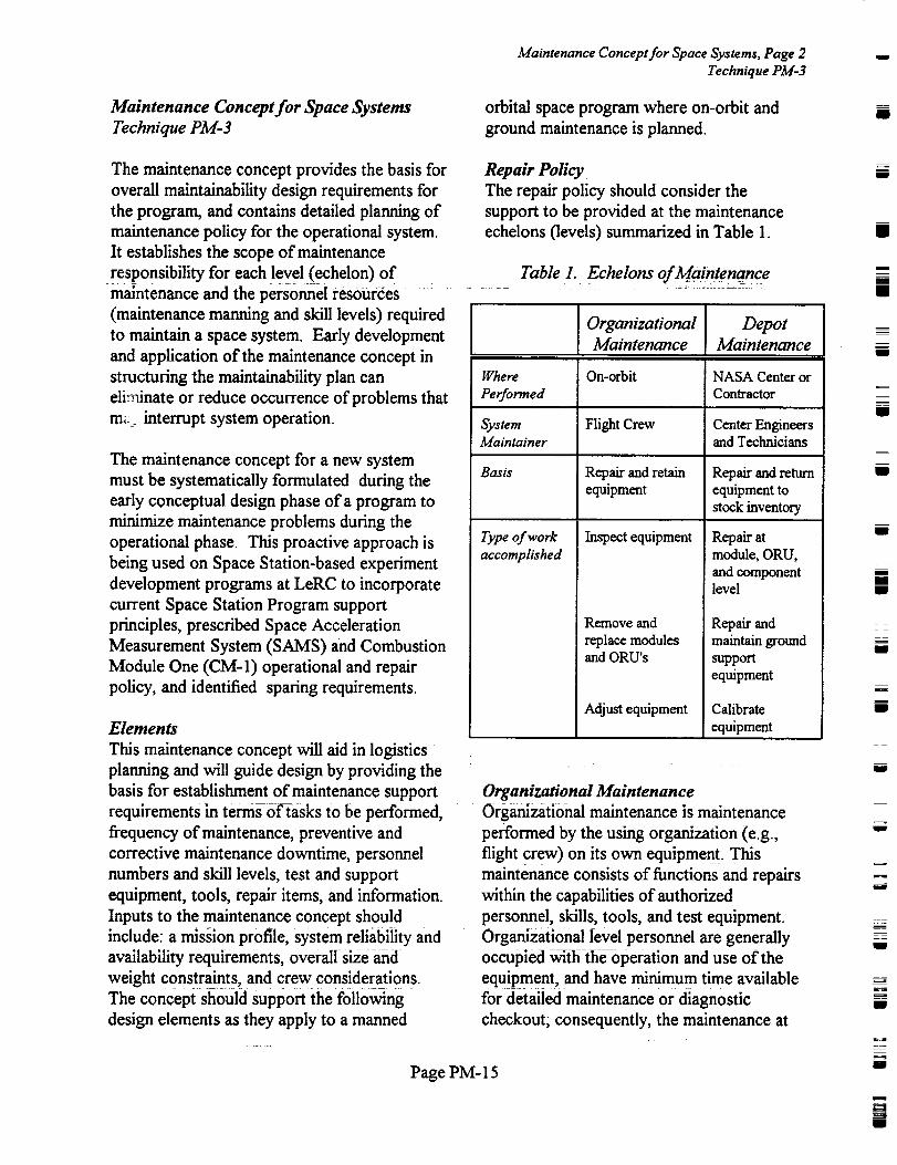
Repair Policy
The repair policy should consider the
support to be provided at the maintenance
echelons (levels) summarized in Table 1.
Table 1. Echelons of Maintenance
Where
Performed
SystemMaintainer
Basis
Type of work
accomplished
Organizational
Maintenance
On-orbit
Flight Crew
Repair and retainequipment
Inspect equipment
Remove and
replace modulesand ORU's
Adjust equipment
DepotMaintenance
ii
NASA Center orContractor
Center Engineersand Technicians
Repair and return
equipment tostock inventory
Repair atmodule, ORU,
and componentlevel
Repair andmaintain ground
support
equipment
Calibrate
equipment
Organizational Maintenance
Organizational maintenance is maintenance
performed by the using organization (e.g.,
flight crew) on its own equipment. This
maintenance consists of functions and repairs
within the capabilities of authorized
personnel, skills, tools, and test equipment.
Organizational level personnel are generally
occupied w_th the operation and use of the
equipment,: and have minimum time available
for detailed maintenance or diagnostic
checkout; consequently, the maintenance at
Page PM- 15
Page 25
w
this level is restricted to periodic checks of
equipment performance. Cleaning of
equipment, front panel adjustments, and the
removal and replacement of certain plug-in
modules and Orbital Replaceable Units (ORUs),
referred to as black boxes, are removed and
forwarded to the Depot Level.
Depot Maintenance
Depot maintenance is maintenance performed at
NASA Centers or contractor facilities for
completely overhauling and rebuilding the
equipment as well as to perform highly complex
maintenance actions. The support includes
tasks to repair faulty equipment to the part
level, if deemed necessary. This level of
maintenance provides the necessary standards
for equipment calibration purposes, and also
serves as the major supply for spares.
@stem Availability
Operational Availability (Ao) is defined as the
probability that at an arbitrary point in time, the
system is operable, i.e., is "up." It is a function
of the frequency of maintenance, active
maintenance time, waiting time, logistics time,
administrative time, and the ready time of the
system, and is expressed as:
UPTIMEA
o TOTAL TIME (1)
Where:
UPTIME = the total time a system is in an
operable state, and
TOTAL TIME = the combination ofuptime
and downtime, in which downtime is the time in
which a system spends in an inoperable state.
Repair v_ Replacement Policy
Normally, on-orbit repair should not be
performed on any plug-in modules or 0RUs. If
Maintenance Concept for Space Systems, Page 3
Technique PM-3
any on-orbit repair actions are planned, they
should be clearly identified in the concept.
At the organizational level, failed itemsshould be either discarded or sent to the
NASA Center or contractor for exchange
and repair in accordance with repair/discard
policies identified in the system
requirements. Corrective maintenance,
limited to replacement of faulty ORUs and
plug-in modules, should be specified to be
performed during the mission period. Prime
equipment should be designed to have ready
access for maintenance. Quick-opening
fasteners should also be specified.
Level of Replacement
The design for proper level of ORU
definition should consider compatible failure
rates for hardware parts within the same
ORU. Relative ranking of ORLPs through
reliability and maintainability considerations
and mission criticality analysis can also
contribute toward the proper level of
replacement definitions. The required level
of replacement should be specified at the
plug-in module and ORU levels.
Maintenance and support of a system should
involve two-tier maintenance echelons. The
first level provides for repair of the end-item
on-orbit by replacing select faulty or
defective plug-in modules and ORUs
identified through use of specified diagnostic
procedures. Faulty ORUs should then beevacuated to the second level of the
maintenance echelon (depot level), which
will be at a NASA Center for repair if
deemed necessary. The particular NASA
center/facility should act as the depot for
repair of faulty items.
Skill Level Requirements
Hardware should be designed to aid on-orbit
and ground maintenance, inspection, and
repair. Special skills should not be required
to maintain a system. The following design
Page PM- 16
Page 26
Maintenance Concept for Space Systems, Page 4
Technique PM-3
features should be incorporated:
• Plug-in module and 0RU design to minimize
installation/removal time and requirements for
hand tools, special tools, and maintenance
skills.
• Plug-in modules and ORUs should be
designed for corrective maintenance by removal
and replacement.
• Plug-in module and 0RU designs requiring
preventive maintenance should be optimized
with respect to the access, maintenance hours,
and maintenance complexity.
• Software and its associated hardware should
be designed so that software revisions/
corrections can be easily installed on-orbit with
minimum skill level requirements.
• Flight crew training for payload flight
operation should identify hands-on
crewmember training, at the NASA center
where the system is built, to familiarize
crewmembers with the removal/replacement ofhardware.
Spares Philosophy
Two basic types of spares should be required to
support a maintainable system: development
spares and operational spares. Development
spares are those that must be identified and
acquired to support planned system test
activities, integration, assembly, check-out and
production. Operational spares are those spares
that must be acquired to support on-going
operations on-orbit.
The quantity of development spares required
for each system, and the total quantities to
sustain the required availability during the
planned test activities, integration, assembly,and check'out test should be determined
according to the following:
• Custom-made components/parts
• Long-lead time items
The quantity of spares required for each
system and the total quantities to sustain the
required operational availability on-orbit
should be determined according to the
following:
• Items that are critical to system operation
• Items that have high failure rate• Items that have limited life
In the initial spares provisioning period and
to the maximum extent practical, spares
should be purchased directly from the actual
manufacturer; i.e., lowest-tier subcontractor,
to eliminate the layers of support costs at
each tier. The initial provisioning period
should cover early test and evaluation, plus a
short period of operation, to gain sufficient
operational experience with the system. This
will provide a basis for fully competitive
acquisition of spares.
Spares with limited shelf life should be
identified and should be acquired periodically
to ensure that adequate quantities of spares
are available when needed. Spares with
expired shelf lives should be removed and
replaced.
Procurement of spares should be initiated insufficient advance of need to account for
procurement lead time (administrative and
production lead time).
The location of the spares inventory (on-
orbit and on-ground) should be a function of
the on-orbit stowage allocation capabilities
and requirements. A volume/weight analysisshould be conducted to determine the
quantity and types of spare items necessary
to sustain satisfactoryoperationai
availability. The volume/weight analysis shall
Page PM- 17
I
w
l
I
m
U
U
u
l
W
m
I
m
g
Page 27
w
U
u
L :
[_
assure available or planned payload volume and
weight limits, and planned or available on-board
stowage area.
Breakout should be addressed during initial
provisioning and throughout the replenishment
process in accordance with NMI 5900.1,
Reference 1. Breakout is the spares
procurement directly from the original
equipment manufacturer, prime contractor, or
other source, whichever proves most cost-
effective. A spare item requirement list should
be maintained by procurement and technical
personnel.
Diagnostic/7"esting Principles and Concepts
The system should meet the following failure
detection requirements as a minimum:
• The system should have the capability to
detect, isolate and support the display of
failures to the plug-in module level. Crew
observations may be used as a method of failure
detection of the following: visual displays,
keyboards/buttons, general lighting, speakers.
• System design should provide the capability
for monitoring, checkout, fault detection, and
isolation to the on-orbit repairable level without
requiring removal of items.
• Manual override and/or inhibit capability forall automatic control functions should be
provided for crew safety and to simplify
checkout and troubleshooting.
• All failures of the system should be
automatically detected and enunciated either to
the flight crew or the ground crew.
• Accesses and covers should be devoid of
sharp corners/edges and be equipped with graspareas for safe maintenance activities.
• Systems/subsystems/items should be designed
Maintenance Concept for Space Systems, Page 5
Technique PM-3
to be functionally, mechanically, electrically,
and electronically as independent as practicalto facilitate maintenance.
The concept should also describe
operating/testing techniques to identify
problems and consider the complexity of the
various types of items in the space system
and associated maintenance personnel skills
(for all software, firmware, or hardware).
The techniques will identify maintenance
problems. In all cases of fault simulation, the
safety of personnel and potential damage to
system/equipment should be evaluated in the
concept. The concept should request that a
safety fault tree analysis be the basis for
determining simulation. Also, a Failure
Modes, Effects, and Criticality Analysisshould be used to evaluate and determine
fault simulation. Some of the fundamental
maintenance actions to be evaluated,
monitored, and recorded are as follows:
• Preparation and visual inspection time• Functional check-out time
• Diagnostic time: fault locate and faultisolate
• Repair time: gain access, remove and
replace, adjust, align, calibrate, and close
access
• Clean, lubricate, service time
• Functional check-out of the repair action
Responsibilities for ContractorMaintenance
The prime contractor's maintainability
program should provide controls for assuring
adequate maintenance of purchasedhardware. Such assurance is achieved
through the following:
• Selection of subcontractors from the
standpoint of demonstrated capability to
produce a maintainable product.
Page PM- 18
Page 28
• Developmentof adequate design
specifications and test requirements for the
subcontractor-produced product.
• Development of proper maintainability
requirements to impose on each subcontractor.
• Close technical liaison with the subcontractor
(both in design and maintainability areas) to
minimize communication problems and to
facilitate early identification and correction of
interface or interrelation design problems.
• Continuous review and assessment to assure
that each subcontractor is implementing his
maintainability program effectively.
Maintenance Concept for Space Systems, Page 6
Technique PM-3
ground processing or maintenance
operations. The rationale for supporting
these recommendations should include
factors such as reduction in ground
turnaround time and operational support
COSTS.
Allocation of Crew Time for MaintenanceAction: _: _
Crew time for maintenance should be
identified in accordance with system
complexity, reliability, and criticality of the
items to the system and mission
requirements. Analytical methods exist
which can be used to prioritize and allocate
crew time for maintenance actions.
i
u
I
lm
II
m
II
U
I
Responsibilities for Payload Maintenance
Director of field installations responsible for
launch preparation, maintenance, or repair
activities should be responsible for maintenance
planning and for providing the resources
necessary to support the efficient identification
of maintenance related problems in accordance
with system requirements. These
responsibilities include:
• Implementing a system that will identify,
track, and status problems related to routine
maintenance activities attributable to the design
characteristics of flight hardware and sofcware.
• Providing information for use in a data
collection system to improve the accuracy of
quantitative maintainability and availability
estimates. This information can be used to
identify failure trends influencing reliability
growth characteristics during design and to
communicate "lessons learned" from ground
maintenance experience.
• Recommending to the Program Manager,
responsible for design and development of flight
hardware/software, areas for design
improvement to increase the efficiency in
RefeYencg$ L
1. NASA Management Instruction, Spare
Parts Acquisition Policy, NMI 5900.1A,
NASA Responsible Office: HM/Procurement
Systems Division, Washington, DC,
November 6, 1992.
2. NASA Management Instruction,
Maintainability and Maintenance Planning
Policy, NMI 5350.1A, NASA Responsible
Office: Q/Office of Safety and Mission
Quality, Washington, DC, September 26,1991.
3. NASA Handbook, Maintainability
Program Requirements for Space Systems,
NHB 5300.4(1E), Reliability, :_ ........ _=_
Maintainability, and Quality Assurance
Publication, Washington, DC, March 10,19871
4. Space Acceleration Measurement System
(SAMS) Experiment, SAMS-SS Product
Assurance Plan, SAMS-SS-005 (Preliminary),
NASA Lewis Research Center, Ohio.
5. Space Acceleration Measurement System
Page PM-19
|
|
II
m
I
mi
w
m
t
U
u
U
m
Page 29
w
w
(SAMS) Experiment, Express Payload
Integration Agreement, SAMS-SS PIA, NASA
Lewis Research Center, Ohio.
6. Space Station Program, Space Station
Program Definition and Requirements, Sections
3 and 4, SSP 30000, NASA Lewis Research
Center, Ohio.
7. Combustion Module One (CM-1) Experiment,
Product Assurance Plan, NASA Lewis Research
Center, Ohio.
8. Blanchard, Benjamin S., Jr. and Lowery, E.
Edward of General Dynamics, Electronics
Division, Maintainability Principles and
Practices, McGraw-Hill Inc., N.Y., 1969.
Maintenance Concept for Space Systems, Page 7
Technique PM-3
W
w
=_
w
Page PM-20
Page 30
wig
mi
i
i
U
i
i
i
U
i
i
aiD
wi
i
i
U
Page 31
|_
|_
Design Factors and
Engineering
The objective of the A4aintainabilityfunction is to influence system design such that the end product
can be maintained m a cost effective operational condition with minimum downtime. In order for
the Maintainability discipline to provide maximum influence to a program, design principles to
obtain these objectives must be implemented early in the design phase. Techniques that have proven
to be beneficial on previous programs are presented in this section as design recommendations for
future programs.
= =
w
F
= .
w
Page DFE- 1
Page 32
II
mmii
z
m
mi
J
I
im
II
i i
II
i
Im
mRB
w
I
m
I
u
u
D
Page 33
J
Selec#on (f Robotically Compatible Faswners" and Handling Mechanisms, Page 1
Technique DFE-1
; 2
ri ,
7 ?
!
w
w
7
w
==:
,,,t..=,
L_
Technique Provide guidelines for the design of maintainable equipment for
compatibility with dexterous robots by outlining selection criteria for
associated fasteners and handling fixtures.
iiiiiiiiiii!iiiiiiiiiiiiiii{iiiiiiiiiiiiiiii!iiiiiiiiiiiiiii!!iiiiiYiiiilliJiiiiiii!iiiiiiiiiiiiiiii!iii!iiiii iiiiiiiiii iiii i_'_'i'_'_'i'i'_'B'_'j_;ii'i_i'i'i'I_,_i'iJi'i':ii'i'iii'i':':i:i:i:i:iiiii_,i:_:':i:_:i:i:i:i:iS_TEiE_'i'Oi'N'i_i'i_'FI_'R_B_|i_ _L:_i:_:_:_:_;i:_:_i:_:_:i:_:_:_:i:i:i:i:i:_:J:_:_:_:i::Miii!iiiifk_l_:_ ::!! ::i_ii!i:2:!i!i::::i::ii::ii::i::i::iii::::i!i ii]iff:ili!i::ii::iii::iiii::::ii::ii!i::::::::_::_i::_::_::_i_::__ i_!: _:_:_:i__:__:_..........._i!i::!_:_i;:!i_;_._i:_::i_i!_:i!i!!_i::!_::_::!i::ii!::i_::i::::ii::i_i_:::_::::_::!::_!!:_::ii::iiii_::i::_i_i_:_!i_!ii_iiiiii::iiii_i_ii::ii:: _ i i _ ii_ _+_#:_i_i::::::::ii!::ii::ii::i_::i_
i!iii_iiiiiii_ii_ii_i_iiiii_ii_ii_iiiiii!iii_iiiiiiiiJiiiiiiiiiiiiiii_ii_i!_iii!iiiii_!!_i_!ii_i!iii_ii_iiiiii_iiiiiiiiiii_i_iiiiii_iiiiii_iiiii_iii_i_i_iiii!i!_ii_i_iD.:_Ei|i_iiii_i_iE_i_i_i_._iM_!iiiiiiii_i_i_iiiiii!_i!ii_iii_iiiiii_iii_
iiiiiii_iiiiiiiJiii!i_iiiii_iii_iiiii_i_iii_!_i_iW_ii_J_!i_iiii_i_iii_i_i_iJ_i_i!_i_i_i_iJ_i_i_iiiii!iiiiiiiiiiiiiiiJiiJii!!i!i!i!i_i!!i!i!i_ii!!ii_Ji!iii!ii!iiiiiii!iiii!i_!ii!_!!ii_iiii_i_ii_i!ii_!i_!ii_!_!ii!_!i!i!i!ii!iJ!i!_ii_!iiiJii!i_iiii_ii_ii_i!i!iii!ii!i!!iii!i!i!_!_!i!_iiiii_!i!_ii!iiJii_i_i!iii_i_i_iJiiiiiiiiiii_iii_i_iii_iiiiiiiiiiiiiiiiii!iiiiiii!iiiii!ii_i_iiii!_i_iiii_i_i_i_i_ii_iii_iii_i_iii_iiiiiiiiiiiii!i_iiiii_ii_!ii_i_iii_Benefits
Key Words
Application
Experience
Technical
Rationale
Contact Center
The application of these guidelines to the design process will increase
the effectiveness of dexterous robots by allowing for optimized design
of robotics components used during maintenance tasks. In addition,
because Extra Vehicular Activity (EVA) tasks performed with robots
must be simplified to accommodate robotics dexterity (which is
intrinsically inferior to that of a human crew member), robotically
compatible designs will facilitate the simplified (less time consuming)
EVA tasks. This equates to less system downtime and higher
availability for both ground and on-orbit systems.
Robotically compatible; maintenance: fasteners; handling fixtures
International Space Station Program
The following selection guidelines enable design engineers to identify
the criteria required for robotics compatibility and to tailor their
specifications to different robotics systems and environments. They
provide general concepts for using robotically compatible fasteners and
handling fixtures that have been applied on the Space Station program
and states the advantages of these concepts.
,lohnson Space Center (JSC)
Page DFE-2
Page 34
Selection _f Roborically Comparibh, Fasteners and Handling Mechanisms', Page 2
Technique DFE- 1
Selection of Robotically Compatible Fa._'teners
and Handling Mechanisms
Technique DFE-I
Before designing an ORU or other component
for robotics compatibility, the feasibility of suchan effort must first be assessed. Some ;tei-ns
(e.g., thermal blankets), because &their
flexibility, cannot be manipulated by robotics
Systemsl The assessment should show (i) if the
ORU or component can be manipulated by a
robot, (2) if not, whether a major redesign of
the_tem will be required to make it robot
compatible, and (3) what effect the redesign
will have on weight and cost (a factor that can
be d-etermined by simple ana]_yses),
Reference 1 describes a preliminary analysis
that might be used to determine the feasibility
of designing for robotics compatibility. Once it
is determined that the item can be designed to
be manipulated by a robot, it must then be
determined how the design relates to and
affects the design of(l) other components in
the system, (2) the system's layout, and (3) the
robotics system with which it will interface
• Provide for alignment.
• Avoid jamming and binding.
• Withstand the loads that may be imparted by
the robotics systems.
• Provide adequate access.
• Simplify the operation .......
• Assist ORUal_gnment and S0_d6ck and
harddock functions. "Softdock" is defined as
the initial temporary attachment between two
or more pieces of equipinen(t_ pre_ent
inadvertent release prior to permanent
attachment.
Reference 2 lists a number of guidelines and
reqt!!ren2ents that may be applicable t 9
designing for-iobotics Compatibility of SpaceStation hardware. Reference 3 lists a number
of different robotically compatible fasteners
and handling fixtures for Space Station use.
The purpose of this technique, however, is to
assist designers in applying the stated concepts
to their system ORU's and not to list
contractual requirements. The six design
objectives for fastener and handling fixture
design requirements are addressed in the
tbllowing section.
Figure 1, which illustrates the process tbr
redesigning for robotics compatibility as
detailed in Reference 1, shows the sequence by
which the design of items higher in a process
flow impact the design of the lower items.
Although the sequence may be altered, the
alteration may result in increased costs, in
schedule delays, and in less flexibility in
applying robotics compatibility. The
bidirectional arrows indicate processes that
should be performed using an integrated
approach that considers the impacts the ORU,
system, and robot design have on each other.
Once the above mentioned analysis is
performed and design of the robotically
compatible fasteners or handling fixtures is
begun, the objectives then must be to:
FASTENER AND HANDLING FIXTURE
I)ESIGN REQUIREMENTS
Provide for alignment
Alignment provisions may be implemented as
(1) markings, (2) alignment guides, and (3)
design of the robotics system and its control
system Only the second of these options,
alignment guides, is addressed in this section.
Markings and robotics system designs are
described in References I, 2, and 3.
Fa,_teners
There are more options available for aligning
fasteners than there are for handling fixtures.
For example, fasteners are captive and are an
integral part of an ORU. Therefore, if the
ORU contains proper alignment features and is
_m
m
I
m
[]
[]
m
I
m
i
m
l
I
[]
m
m
m
m
!
w
F_
!
Page DFE-3
I
Page 35
Selection of Robotically Compatible Fasteners and Handling Mechanisms, Page 3
Technique DFE-1
o
- i
L_w
w
Revise
Robot's
Pa rameters/
Capabilities
+Dr.fine Factors of SalYtv
for Loads
Determine/Revise
System'sParameters
. ,
2
W
t
Define/St'lcct Fastener Type,
Torque Values, and
Location
DefiJle/Design Targets Iand Markings
Dennc/Sek'ct Handling
Fi_llll't_ ._lll(| Lo¢;itiou
Define/Design ]Alignmenl Guides
= :
¢,7
w
_=_
FigTire 1. f'roce+s'x for RohrJlic'._ ("om/_alihi/iO_ De.s_q77
properly aligned and inserted, the fasteners will
be properly aligned as well. However, since
handling fixtures are grappled independent of
the insertion and alignment of the 0RU, the
incorporation of alignrnent features is confinedto the fixture and end effector. The ORU
alignment feature design, which is discussed in
References 2 and 3, is an important
Page DFE-4
Page 36
Selection of Robotically Compatible Fasteners and Handling Mechanisms, Page 4
Technique DFE-1
consideration, since it can lessen fastener
complexity. The alignment techniques being
used for Space Station fasteners are described
below.
Alignment of Tool to Fastener Head
Robotic testing has shown that, provided there
is proper visual contrast between the fastener
head and the surrounding structure, a 7/16- inch
fastener with a flat head can be easily captured
by the robotics end effector (nut driver).
Earlier concepts specified or recornmended
rounded heads because it was believed the
rounded head would accommodate greater
misalignment tolerances. It was found,
however, that a flat-headed fastener provided
the robot with the same misalignmenttolerances as the same fastener with a rounded
top.
Alignment of Fastener to Nut
The bolt is aligned to a nut by tapering the end
(pilot) of the bolt and by having a cone orcountersink around the nut. For fasteners that
form an assembly or that are, in Space Station
terminology, "attachment mechanisms," there
are housings which contain tapered "fingers."
Handling FLvtures
The two alignment techniques for Space Station
handling fixtures are described below.
V-slot Insertion
The V-slot insertion technique is used with the
microfixture and H handle, which interface with
the Special Purpose Dextrous Manipulator
(SPDM) end effector or the ORU tool
changeout mechanism (OTCM). The OTCM
fits as a V into the grooves of the H handle
closes its V-shaped grooves around the corners
of the microinterface (see reference 2 for a
detailed description). The positional
misalignment tolerance allowed for the H
fixture is approximately 0.5 inch with angular
misalignment tolerance of about +2°. The
microfixture allows positional misalignments of
about 0.3 inch and angular misalignments ofabout +3 °
Cylinder-over-cone
The microconical tool slips over and attaches
collets to the microconical interface, which is
shaped like a cone. The allowable translational
and angular misalignment tolerances for the
microconical tool are 0.25 inch and +1 °,
respectively
A VOID .lAMMING AND BINDING
Fltsteil ers
Once alignment is accomplished and the
fastener begins to enter the nut, th_e_r¢is still
the possibility of cross-threading Cross, _
threading can be avoided by aligning the nut
using the unthreaded portion on the bolt, and it
can also be avoided by using an expandabie
thread diameter nut; i.e., a Zipnut. A Zipnut
consists of three separate segments within a
housing that, when assernbled, form the
internal threads of a nut. The segments are
held against the threads of a bolt or screw by
springs that force them to a minimal diameter,
and a ramp that allows them to separate or
come together, depending on the direction in
which the bolt is inserted. When a bolt is
inserted, the segments are allowed to slide
back and away, allowing the b01t to slide
through without obstruction. This type of nutis described in detail in Reference 2.
Handling Fixtures
When using robotically compatible handling
fixtures which apply the slot in the V-groove
concept as described above (i.e., the
microinterface or X handle), care must betaken that the corners are rounded. This
precaution must be taken to keep the handle
from binding to the end effector, as happenedin t]ie JSC _?obotlcslabora;cories with the firs(
H handle concept which had sharp corners.
Page DFE-5
mi
m
u
i
=--
=
Zmu
Ill
z
!
I
i
g
W
J
ii
U
Page 37
r
-2
m
_-7
w
w
W
w
w
L_2
Z=i
a =
= .
Selection of Rohofically Compatible Fasteners and Handling Mechanisms, Page 5
Technique DFE-I
The corners of the H handle (renamed the X
handle) were rounded, and the binding effectwas thus eliminated.
WITHSTAND LOADS THAT MAY BE
IMPARTED BY ROBOTICS" SE._TEMS FOR
FASTENEIL9 AND HANDLING FIXTURES
SSP 30000, table 3-3, "Factors of Safety,"
specifies that for metallic flight structures, the
general factor of safety is a yield of 1.25 and anultimate of 2.00.
PRO VIDE ADEQ UA TEA CCESS
Fasten ers
Adequate access for fasteners is provided by
designing a proper layout of the system asdescribed in reference 3. The fastener selection
(or fastening scheme) can be influenced by the
robotics access if more than 1 degree of
freedom is required by the robot to engage and
disengage the fastener. A lever, for example,
requires more than 1 degree of freedom and
therefore requires significantly more access
space to operate than that required to engage a
bolt. In addition, the higher the torque value,
the larger the end effector (motor), lessening
the allowable robotics access space. For Space
Station, no levers will be used by robots.
Handling FLvtures
Certain small Space Station ORU's are being
placed so close to each other that inadequate
access space is provided for the robot to open
its jaws around the interface. The problem was
resolved by using the microconical interface
that snaps around the interface in a "stabbing"
motion. By using a tool that does not require
jaws to open around an interface: i.e, the
microconical tool, the required access space is
significantly reduced.
Simplify the Operation Fasteners
The robotics operation can be simplified by the
following methods:
Use Captive Fasteners
Use of captive fasteners is the best method for
simplifying robotics operation. This eliminates
the need for the robot to carry and insert the
fasteners and thus increases the probability of
mission success.
Reduce Number of Operations
The type of fastener selected can reduce the
number of operations required. For example,
using the Zipnut eliminates the need for
rotation, since the bolt can be slid through the
nut and then tightened with a single rotation.
Choose Proper Forms of Fastening
Forms of fastening that require the robot to
use more than 1 degree of freedom should be
eliminated. Levers, for example, not only will
increase the access space requirements (as
described previously), but may also
necessitate force moment accommodation and
more complex control software.
A void Fasteners Requiring Excessive Torque
To engage fasteners that require excessive
torque (ie., 50 foot-pounds or over), the robot
must stabilize itself with one arm, constricting
the allowable configurations for removing and
replacing the ORU. This necessitatesadditional hardware for robot stabilization. In
general, care must be taken when using robotic
systems for fasteneing due to the reaction
forces that will be present.
Reduce Sizes and T.vpes of Fastener Heads
Using different sizes and types of fastener
heads will reduce the number of tools required
by the robot.
Handling Fbctures
The grasping of the interface can be simplified
by allowing the robot to grasp the interfacefiom a number of different orientations. For
Page DFE-6
Page 38
Selection of Robotically Compatible Fastener_" attd Handling Mechanisms, Page 6
Technique DFE-1
example, the microinterface and the
microconical interface can be grasped from two
different orientations of the OTCM relative to
the handling fixture, while the X handle can
only be grasped from one orientation, There
may be some instances, however, in which it
would be advisable to limit the allowable
orientations. For example, if the robot can
grasp an ORU from only one orientation, there
is less chance that the ORU will be improperly
inserted in its base plate.
ASSIST ORU ALIGNMENT AND
SOFTDOCK AND HARDDOCK
FUNCTIONS
Fasteners
When designing robotically compatible ORU's,
the alignment guides and softdock features may
be incorporated as part of the ORU, or
fasteners with these features may be designed
or selected. Sofldock fasteners are thus more
complex and are called "attachment
mechanisms" in the Space Station Program.
Alignment and sofldock functions are describedbelow.
Alignment Functions
If alignment features are lacking for the ORU,
they can be incorporated via the tapering of
pins, or fingers, located on the housings of theattachment mechanisms.
Softdock Functions
For the Space Station Freedom Program,attachment mechanisms achieve sofldock either
through the use ofdetents that are housed on
an outer casing of the attachment mechanisms
or via the Zipnut method. The Zipnut is
ramped such that if an attempt is made to
separate the bolt from the nut, the segments are
pulled together allowing the bolt to be remo\,ed
via rotation only. The Zipnut thereby functions
as an excellent sofidock attachment.
Handling FL,ctures
Alignment and sofldock functions aredescribed below.
Alignment Functions
The location of the handling fixture can
significantly impact ORU alignment. The
further the handling fixture is from the ORU's
center of gravity, for example, the mote -
difficult it is for the robot to maintain a line of
insertion that will be perpendicular to its
attachment plate.
Other factors to be considered when placing
handling fixtures are the size of the ORU, the
location and type of alignment guides, and the
placement of fasteners. These items are
discussed in Reference 3 because of their
dependence on ORU features.
So.fidock Function
Softdock features may be used to prevent an
ORU fi'om "floating away" prior to its being
fastened. This may also be achieved by
fastening the ORU without releasing the
handling fixture. The three above mentioned
handling fixtures for Space Station have holes
in their centers for fasteners, which allows the
OTCM to grasp the ORU, insert it, and thendrive the bolt with its nut driver without ever
releasing the ORU handle.
Re[erences
1. t?ohoticx System_ htter/'ace Standards,
I ?drone l, Robotics A ccommodation
Requirements (Draft), SSP 30550.
2. Rohotic'x ,S);stems Interlace Standard.',
}drone 2. Robotics Interface Standards"
(Draft), SSP 30550.
3. 7he [)e.s'i_l Proce.s:sfor AchJevJng
Robotics (;ompatibJlity, Contractor Report
No. <TBD>.
Page DFE-7
i
m
I
I
i
I
g
B
i
l
mm
i
I
I
mm
i
u
m
W
u
J
R
Page 39
r_
w
w
_.i
False Alarrn Mitigation Techniques, Page I
Technique DFE-2
Technique
:::::::::::::::::::::::::::::::::::::::::::::::::::::
#iiii!i/i/ii:, :i::iiiii::ilii/i/jii!/!!
iii_iIiiii_i_!i_iiii_iiIi_Ii_iiIii_iI_ii_iiiiiiii::_iiiiiiii_iIiiii_iiii_ii_ii
::::::::::::::::::::::::::::::: :::: : ::_:::. :, ,...,..::"_i_'_/i_._i_'_'_!i_-_!:_::::::::::::::::::::::::::::::::::::::::::::::::::::::: !'":..::
:::::::::::::::::::::::::::::::::::::::::::::::::::::::::::::::::::::::::::::::::::::::::::::
Benefits
Key Words
Application
Experience
Technical
Rationale
Contact Center
Minimize the occurrence and effect of Built In Test (BIT) false alarms
by applying principles and techniques that are intended to reduce the
probability of false alarms and increase the reliability of BIT in avionics
and other electronic equipment.
::::::::::::::::::::::::::::::::::::::::::::::::::::::::::::::::::::::::::::::::::::::::::::::::::::::::::::::::::::::::::::::::::::::::::: : :::-:::: :::: ::_. .._.'.._.-_-.+-..._ ...... _.q::._.:. ......
_ _i i _i i _ _i_/! i! i _:'.' ".x::._:_::::._:: :::::::::_: :::::::::::::::::::::: :_ _:::: :.,.::'.:::::..,:_::_:.,.':: _:_:_:_ _:::q::_?:_::::::_.'.':i:':ii" !:!:_._:!:!:!:!:_:!:!:!.'.:_:_:_i i:_:i:_:_:__._?.':_'."i:i._:i:_:_:_:_:_:.!!_::_ i i:;:_:i_:::!:_5! _ i _i__i _._! i _! _i_! _:!
_li!_i!!liii!i!i!ii!iiliiiI_!_!_iif/i_:_iiiiii!ii_iiii!i)iiii!i_i_i_i_iiiiiii/iiii!i!ili!iiiii iiiiliii_iii!!_i_i_i_;""'f_____iiiiiiii::iiiii"'"ii_::"'iii"'!i"'::i"_i"!_:''::_.............if"i::iff:f"]i::::%i_ii!i#:ii_::!_::_i!i_i!!ii_iiiiii_::!_!i!!::!!iii!iiiiiii_ii_iIiiiiiiiiii_iii::ii_i_iig_::_i_i_ii::_i!_iiiiiiiiiiii i ilii iiiii iii lli ii!i.__:, _ i_ _.__._i_,_:_!i!_ii_i_._:q:!:_:._i:;i_:_:.._.,'_:_::?..:._:: :_:_ ::: ::: :::: _:: ::: ::: _:._: :i::: :_:i:_._ _:_ _:, _._ ::_: :: :_:: _ _:. _::.:.'..-"::_._':::: :._:_ :_:: :_':_._:_: _: :_ ::: ?..:_'.._::_.:::_g:: :._::: ::::.".:_.::.>_:::::::::::::::::::::::::::::::::::::::::::::::::::::::::::::::::::::::::: :::.:.:.:-!:_,.:...,..:,. :._. ,._:..,_...:._._ .:..: ....... +...._ ................. _......._..._ _.:: _,_. - .._.._ _............ x.:.- .:.:.:.-:-.:.:.:.:_.:_....:.:::::::::::::::::::::::
::::::::::::::::_:::::_:_'..:_ _:_:._::._?._!_._:':_._i_:'.._!?:i _'?." i :?i..'..:i:_:_:i._.__: ::/_ : :::::::::::::::::::::::::: :::::::::::::::::::::::::::::::::::::::::::::::::::::::::::::::
:: :::::::::.,.: ::::::::::::::::::::::::::::::::::::::::::::::::::::::::::::::::::::::::::::::::::::::::::::::::::::::::::::::::::::::::::::::::::::::::::::::::::::::::::::::::::::::::::::::
_::..:._:.::"::::.:::::._.::::::::::::::::::::::::::::::::::::::::::::: ============================================================================================================================================================================================================================.. . .
:.: '?:..'.' _.'._..../.._....._._._......,._..,. ........... ......_.... _. >......... _........................... _ <_.:.• .:........ __..._...... _....,.:+, .... ....... +.. ::....... . ,.,..:.. _., .::. _.,..._, ,_ ........... _. _¢<_
:!:!"!P'"::!:!_;i'_!_:i:i!!_i_:ii_:%:%!_!i!i!_?:i%!:'!;_:::.:. 'ii:_!:_::::li.............i!":!ii:':"%::!_i:";!!i;!i_;:!ii_::!_i:"!i!_!i!i!;i_!!'.,'.i:i_;i_/:_:_-:'_!i:%_itli_!_i_i/_j_ii_.';..'::_!iliii_!!.-11_lt¢i!i_i_i!ii!i#iil
Effectively implementing BIT techniques automatically reduces the
number of BIT false alarms. Decreasing the number of BIT false alarms
increases a system's availability and decreases the maintenance man-
hours required. The overall result is a reduction of the system's life
cycle cost.
Anomalies, Built-In-Test, False Alarms, Circuit Monitoring
International Space Station Program, National Space Transportation
System
The reliability of a system's BIT can be determined in part by the
number of false alarms it experiences. If the BIT can not accurately
identify and report the occurrence of failures then the test has failed its
mission. Testability must be treated with the same level of importance
as other design disciplines. BIT reliability must be considered just as
critical as any other performance requirement. A system can not
perform its mission if its components are constantly being removed forfalse maintenance.
Johnson Space Center
===
w
Page DFE-8
Page 40
False Alarm Mitigation Techniques, Page 2Technique DFE-2
False Alarm Mitigation Techniques
Technique DFE-2
the test data reported while only requiring a
single computer or processor.
In order to mitigate false alarms, a system's
Built In Test (BIT) circuitry must be able to
cope with a limited amount of anomalous
performance. NASA Handbook 5300.4 (1E)
defines a false alarm as "an indicated fault
where no fault exists." Based on this definition,
this technique is concerned only with BIT
_" _nd]cadons0f system mai_ncdoh-ffhi_'-cause
Continuous Monitoring
Continuous monitoring with BIT filtering can
be used in place of the voting scheme. With
this technique, BIT results are based offa
integration of successive measurements of a
signal over a period of time instead of a single
check of the signal. The monitoring of the
signal does not have to be continuous but only
sampled over the time period. -The-fi-lteHng
unnecessary maintenance a_ions.The inabiii@ .......i_olves comparing the current reading of a
of a system to detect or report the occurrence signal with past and future readings of the
of a failure, a "fails to alarm condition", is not a same signall This filtering aI!ows for the
false alarm and is not addressed, disregarding of sporadic out-of-limit
measurements. Only when a signal is out-of-
BIT should be designed to distinguish between limits for a predefined time limit or a sequenceactual failures and anomalies which must be
tolerated due to adverse operating conditions or
that are normal anomalies within acceptable
limits. To accomplish this, the following
principles and techniques must be mandated in
the system specifications, requirement
documents, and design policies and
implemented in the system design.
Voting Scheme
One technique is called the "Voting Scheme."
With the voting scheme, all test data are
analyzed by three or more different computers.
A failure is declared only when a majority of the
computers detect the same failure. An example
of this type of architecture is the Space Shuttle
Orbiter Avionics System. The five General
Purpose Computers (GPCs) are allinterconnected to the same 28 serial data
channels. The GPCs perfo_ ai[system-level
processing and require a majority agreement on
all test signals. This technique requires an
extensive use of resources but is extremely
effective at mitigating false alarms. A less
complicated version of this is the use of double
or triple redundant monitors. Having two or
more sensors in series increases the reliability of
of tests identify the same failure, should the
BIT flag be set.
To maximize the effectiveness of continuous
monitoring, the BIT data must be recorded.
Once recorded, the data need to be
summarized and evaluated so that trends can
be tracked and weaknesses identified. To help
manage all this data, controls should be
implemented. The number of signals
monitored and the maximum sample rate can
be limited. The time span over which data are
collected should be set at a reasonable period,
and the type of data accumulated should be
restricted. Finally, computing techniques can
be used that do not require the storage of old
data. Once the information is gathered, a
failure log should be created.
This failure log is the basis for future
modifications to the system's BIT. To improve
the BIT, every instant of anomalous
performance not related to an identified failure
mode should be analyzed and the root causes
identified. Some form of corrective action
must be taken to avoid recurrence. Ira design
change cannot be made, then the BIT must be
mI
D
I
U
mu
m
D
= =immm
i
II
w
w
n
i
D
Page DFE-9
mm
Page 41
False Alarm Mitigation Techniques, Page 3Technique DFE-2
_=_
w
k=O
L
W
W
y
Sb='O
modified to accommodate the non-failure
causing anomaly.
The need for modification requires BIT to be
flexible. Test parameters and limits must be
easily changed. The operator should be able to
control or even change the test sequence. This
flexibility allows the necessary changes in the
BIT to be made if false alarms start occurring.
For example, the Space Station's Command and
Data Handling System uses programmable
Deadman Timers in the multiplexer/
demultiplexer (MDM's) and standard data
processor (SDP's). The response intervals of
the timers can be adjusted by the system
controller to accommodate changes in system
configuration or mode of operation. However,
the BIT software must be changed without
disturbing the system operation. For this to be
possible, the BIT soi_ware must be independent
of the operating software.
Decentralized Architecture
Another technique for mitigating false alarms is
the use of a distributed or decentralized BIT
architecture. With this approach the BIT is
implemented so that a "NO GO" on a given test
directly isolates the implied failure to a
replaceable unit. Locating most of the BIT
internal to a unit greatly reduces the possibility
of incorrect isolation of a failure. Although the
decentralized BIT concept consists primarily of
unit level tests, some system level testing is still
required.
An excellent technology for combining unit
level testing with system level testing is
boundary scan. Boundary scan is the
application of a partitioning scan ring at the
boundary of integrated circuit (IC) designs to
provide controllability and observability access
via scan operations. In Figure 1, an IC is
shown with an application logic section,
related input and output, and a boundary scan
path consisting of a series of boundary scan
cells (BSC), one BSC per IC function pin.
The BSCs are interconnected to form a scan
path between the host IC's Test Data Input
(TDI) pin and Test Data Output (TDO) pin,for serial access.
During normal IC operation, input and output
signals pass freely through each BSC, from the
Normal Data Input (N-DI) to the Normal Data
Output 0qDO). However, when the boundary
test mode is entered, the IC's boundary is
partitioned in such a way that test stimulus can
be shifted in and applied from each BSC
output (N'DO). The test response can then be
captured at each BSC input (NDI) and shifted
out for inspection. Internal testing of the
application logic is accomplished by applying
test stimulus from the input BSCs and
capturing test response at the output BSCs.
External testing of wiring interconnects and
neighboring ICs on a board assembly is
accomplished by applying test stimulus from
the output BSCs and capturing test response at
the input BSCs. This application of a scan
I TDO
BSC " _-_
APPLICATION
LOGIC
TDI
BSC
OUTPUT
Figure 1: Built In Test Architecture
Page DFE- 10
Page 42
path at the boundary of IC designs provides an
embedded testing capability that can overcome
test access problems. The unit level tests can
also be combined for a subsystem or system
level verification (Figure 2). More details on
applying these techniques are in IEEE
Standards 1149.1 "Boundary Scan" and 1149.5
"System and Maintenance Bus."
Finally, high-reliability components should be
used in the design. The reliability of the BIT
hardware should at least equal or exceed that of
the hardware it is testing. The BiT software
also needs to be thoroughly tested and verified
to ensure that it will not be a source of false
alarms. Accordingly, adequate amounts of
effort and resources must be allocated during
the design phase. The designer should not be
unduly limited by memory size, component
count, or any other allocated resource.
These guidelines are not all inclusive. The
false alarm problem is very complex. Each
system is unique and must be approached
differently. The best approach is simply toeliminate each factor as it is identified.
False Alarm Mitigation Techniques, Page 4
Technique DFE-2
References
1. Coppola, Anthony, A Design Guide for
Built-In-Test (BIT), RADC-TR-78-224, April1979.
2. Malcolm, John G., Highland, Richard W.,
Analysis of Built-In-Test False Alarm
Conditions, RADC-TR-81-220, August 1981.=
3. NASA Handbook 5300.4 (1E),
Maintainability Program Requirements for
Space Systems, March 10, 1987.
4. Texas Instruments Inc., TESTABILITE,
Test and Emulation Primer, 1989.
W
I
l
m
i
II
m
I
I
I
m
!
lI
__=ml
m
m
IC TEST
BOARD TEST
SYSTEM TEST
BOX TEST
_ii_i..`:@_:.:ii.:_:i!!_.:_!_:i!!i!_!!:'..!_!i:.!!!!_i_ii!_ii_!_!!_i__iiiii::_s.:_i8._i_.:_.)_i_i_i_.::!:_i_._i_i:i_!_._!_:._._i:i_i_!:!_!_?.i:!_._:!i!i_i_iii_: ....... __ii.iii!_i_i:._ii._i!_!.!i_._i.:i_i!i_i_i_.':i!i_ii:_._:_!_i_i_i@!_!_:@!__!i!_.! ...._]_`%_i[i._:_:[:_:_:[:i:i:i:i:_1i].::i:?:i:i:_:_i:i:.:i:i:i:i_.:i:i:_:::i:_@!:_:!:_:_?:':':
::::::::::::::::::::::::::::::::::::::::::::::::::::::::::::::::::::::::::::::::::::i_:i:_::_._j:
iiiii;i:@ii::i_;::ii_::;i;i::i_;i'_::;i_ii_i!?.:_i_!!;ii::__i::i _i::iS_
Figure 2: Typical Test Regimen for Space Systems
===1
g
m
m
=1w
m
I
Page DIE-11
mg
Page 43
7
w
-__:_
w
AnalysisAnd
Test
w
w
Maintainability analysis is a very important part of the design process in which aspects of the
maintenance concept are quantified and design decisions are made based on results. Hardware and
Software testing not only verifies that the item(s) in question will perform within the specific
environment, but also allows for maintenance items to be identified and verifies maintainability
design features. The techniques containedwithin this section describe a wide range of analysis and
test processes used within the NASA community and should provide a vehicle for education,
communication, and continuous improvement.
u
Page AT- 1
Page 44
I
I
mzZI
IB
mm
ID
_rm
m
[]J
Z
m
lid
iI
gm
L_
lm
i
w
w
qmw
I
Page 45
k.a
F_
t J
w
o ,
Neutral Buoyancy Simulation of On-Orbit Maintenance, Page 1
Technique AT-1
Technique
_!._li_._'..,.'i_._!i_ii._!_! :_:_ _:_
!ii!ii iiiiiiii!!iii!iiilliiill illil iiiiiiiiii II/_:!:i:i:_:_:_:i:i:_:_:__:::_:.'.5!_[i!ii_!;_ _._i_i_ii_i.":_!_i_(:':..'.'__ _.':_:'_.".._
_._......... _...!:?... :: .-_:....._..._.:.:_::.:::::::
._:::_:::._:::_.::::::_::.:i:_i!_!i__:_:_i_;i_..'.'?.i_._iii
iiiii/iiiiiiilt ii iii i!i!i!iiiiiiiiiiiii i i !ii ii!i
Benefit
Key Words
Application
Experience
Technical
Rationale
Contact Center
Simulate on-orbit space maintenance activities by using a neutral
buoyancy facility to assist in making design decisions that will ensure
optimum on-orbit maintainability of space hardware.
i_!'!_ _ _._:._ii_i::::._::_::_::_:iii_i_i:_.:_§_i_._:ii_`..i_!_.`..._::::.`..::_:::_':_.::_.`..:::_ii:_:i:::i::_._:_!._.`:!i:_i_i::_:: : ::::::::::::::::::::::::::::::::::::::::::::::::::::::::::::::::::
::_.q:::._:: :::._:: _::._ -_::_:: :::- :_:::: :.¢:.¢.__:: :::_:._._:::'.: :__:: ,¢:: _:_.::_:_:_:_.'.:.__::_¢? _:_5:i:_:':_:._:.'.'_:.:_:: _¢..-:_: _::: 15:;: _.::._:::: _::: ::::: :._:::._ ._:::::::_: _:::::::: _:::::_::_:::: _::: :::::: :_,-'.:::_:::: :_: :::.¢:::i._ii_i_._:'.._ _..'.. _..'._i_._._._!_:._:..`.._:`.._.`..:::¢:::.``_i:_::::`.._._`::_._::_._:_::_!::! ._._.,.. ., _ _ .._........ _..................................................::::: :8:_:::: ::::: ::: :'_::: _:':.'2:: _:_ :.::_:. _.:.:::+:.:.:.:.,_:.:.:.:-:.:.:.:.:.:.:._.:..:: ....... ,'._ _....... _-.,. -_ +_ ._ ..--:.. _. ....... '..* -._.'... :_,'.• -., ...... :: ::;::: :'.'::: .'.':_:_.".':_::._ ::: _::: :_-'.'_:::_:: _ ?.,','._:::_._,:_::::::::
_:._._ii_#_.:#_.:..._!_::_:_:::_!_:.._i_._i_!_:::_._...:.`:_?.._:_:_:_;:_:_:_:_:_:_:_:_:_:?_:_:_._:_:_:_:_:_:_:_i_::_.`.._:_:_:_i_..._i:_-:_._`._
:::::::::::::::::::::::::::::::::::::::::::::::::::::::::::::::::::::::::::::::::::::::::::::::: . ..::::'.: .... :::::::::::::::::::::::::::::::::::::::::::::::::::::::::::::::::::::::::::::::::::::::::::::::::::::::::::::_._::_._._.-.'..._._--======================================================::,_.:...::_.:::_.:..:;_i_!i:.:.::-_.:..::.'..:-_ .-.._._...,....... :::::::::::::::::::::::::::::::::::::::::::::::::::::::::::::::....,':_'_.:-:.+:.:::.:.:::.:.:::::_::::::_.¢:_:::_'_¢_':: ..... _2 '_'_. ....... ::"_ ........ _..._...+..._._?._:_:::::_::::::::::::::::_:_:._:::.::_:._:_::::_.::_:::: :: :::::-¢:: : _::_ _ _ ._:' _ •":':'_:_'+:+:':':':'":':"_:'" _._."_.:_.:._.:::_._.._:::_..._.....::...:_::::._:::_._:::::::::::._:_.:::::::.::::_._:.:::._:::.:::_::::._.`:_::_: .< _ .._'_. ' .'::_:_ _ ' _ _2" .':::.'::.:. ::_.::::.::.:::+::.:_:.:.:+:.:_-5:::.:.:.:+_..,:.,.:...._.. -..-_.._.,_..-_ ...... _.......... _._ ....... _'--'.'_':.<'-_.+'.-...._+..+:.-.*._:-..'....._,_......_.-._._5 _ _::-: _ _. :::::: :::::::_" ::'" :::::::::i _:_:i:i:_:_i:_:i:_:_:_:__:!:_.'.':_:___:_::"i:i:i:_:i:_!:!:i:!"':_:i::::'._ .".'_:.'.':: : :';:_:::: _.:: :.'.':-_::::: ::'_ "": :._.'_ _: : _ : .'.':!:_:.'.::_::"""" :_.,.'_:_:_'::_/: _: :_:.,.':::: :_:: ::: : : : :,,._:: _::::: ::::::- "::::::: _:: _::: _:: :::__: : :
i:_i__i__!____i._...'.'__!_'_i_ii:iiii_ii_i_li_i_:iii'::"" " . : " ..i:: ,.'" .i:_" " ....... . . ::_:' " !:." : '. :' .._::_:_i:_:!.'.':i:i:!:i:i:_:i:i:i:::i:_:_!::_:_.:_::'.i:i_._:_:i:i:
": : +' _"............... _"-"_i _'" "" " ........ _ +'"' +'" '::::::::::::::::::::::::::::::::::::::::::::: "::' :' :::" _:_'" +_ ................... _ ......... +'_ " ....... _'"'" :_:....... + "" _'" _'_ _"'"'" _'''• " "':'"! ..... i"_' :: ....... •....... ::::::::::::::::::::::::::::_::.'..:::_:::_:!:!`::_:._!..`._?:!_!_:_:_:.:._._!ii!_ ..'.'._!_! :_._:::-_::._:_ -'.'_! ?." _ ..'.'_: ::_:_ :._,_:.,'::::.'.'::::
::::::::::::::::::::::::::::::::::::::::::::::::: _ ::::::::::::::::::::::::::::::::::::::::::::::::::::::::::::::::::::::::::::::::::: _'::: ._:._ _: ._ _ _.,'_ Z_ _- ,_::_ '_S_ :"." :
_iI!i_':_i_iiIi::i_ii_i_ii!_ii_i_iiiIi_i_I?:_i_i_ii?:i_!_i_i!_iI_Ii_i_i_i_ii_ii_I_iiIiIi_iIiIi_i_ii_i_`i`:_iI_i_;iI_i_i_i::ii_i_::_i_I!i_iIii_i_iiiIi_i_iii_i_i_i_ii_ii_i_ii::_i!_._i!!_i_i_ii_ii_iiiI!_i_iiii_iiiii_iiiii_i::ii::i::i_i_i::?:i!iii_Ii::i!_i_!_!_i_i_
Neutral buoyancy simulation can provide valuable information for
designing-in accessibility, modularity, simplicity, and standardization. It
can also provide cost-effective, specific design information on the
effectiveness of crew stability aids, crew maneuvering aids, specialized
tools, and operational timeliness. Maintainability criteria that can be
established by utilizing this process include: component accessibility;
fasteners accessibility, systems installation; and the configuration and
operation of crew stability aids and tools.
Neutral Buoyancy Simulation, Maintainability Design Criteria, Space
Maintenance Activities, On-Orbit Maintainability, Simulated Weightless
Environment, Orbital Maintenance Special Tools, ORU
Skylab, Hubble Space Telescope, Space Shuttle Orbiter, International
Space Station, Apollo
Equipment and crew interface testing in a simulated weightless
environment at an early development stage in NASA programs is an
accurate means of assessing hardware and tool design features and
determining crew capabilities and requirements. While other forms of
weightlessness simulations (e.g., parabolic flight, motion base, and
computer models) have proven effective in specific applications,
underwater simulations have proven particularly beneficial in hardware
development, crew/hardware interface design, and operations planning,
since they can accommodate a large worksite volume and extended testtimes.
Marshall Space Flight Center (MSFC)
.. Page AT-2
Page 46
Neutral Buoyancy Simulation of On-OrbitMaintenance
Technique A 7'-1
Neutral Buoyancy Simulation of On-Orbit Maintenance, Page 2
Technique A T- 1
T.V. monitors, communications with test
subjects, audio/video taping capability,
pressure and de, th displays of test
subjects, and lightning warning systems.
u
The neutral buoyancy facility at MSFC has
beenused since 1968to effectlve-ly simulate
the weightlessness of space, and has assisted
in th-e establishnaentpf rnaint_nabilFty design _
criteria, particularly in extravehicular activity
(EVA). Use of full-scale neutral buoyancysimulations has also allowed for direct
human participation in test operations, as
well as for access to the large body mock-up
hardware _veloped for EVA simulations.
These methods are a very effective way of
simulating on-orbit environments for the
purpose of verifying and solidifying
operations :._.d maintenance procedures.
Other neutral buoyancy facilities used for
NASA hardware development and test and
crew training are the Weightless
Environment Test Facility (WETF) at
Johnson Space Center, the Neutral
Buoyancy Research Facility at-the University
of Maryland, College Park, Maryland and the
neutral buoyancy facility at McDonnell
Douglas, Huntington Beach, California.
Neutral Buoyancy Characteristics
The MSFC neutral buoyancy facility has the
following overall characteristics:
Six-console control room.
• Three-person, double-lock hyperbaric
chamber.
Floating crane for underwater movement
of hardware (one 2000-pound hoist, one
500-pound hoist).
• Removable roof section to accommodate
large hardware.
Support of up to four Shuttle space suitedcrew members.
• Umbi!ical'supplied underwater primary
life support systems.
• Operational Remote Manipulator Systems
fP.MS).
• Air-lock for emergency test subjectevacuation.
=*lae neutral buoyancy tank within the facility
is a 1.3 million-gallon water tank that
measures 40 ft. deep and 75 ft. in
diameter. The water temperature is
maintained at a range of 88 to 92 degrees
Fahrenheit and a pH of 7.50. Cathodic
protection systems are used to inhibit
corrosion. The tank accommodates up to
four pressure-suited test subjects
simultaneously. Extravehicular Mobility
Units are available for four test subjects.
The tank can accommodate test durations of
up to 6 hours.
lIST Simulations :
Underwater simulations in the neutral
buoyancy facility strongly influenced the
maintainability design criteria for the Hubble
Space Telescope (I/ST) and its components;
particularly with regard to visibility,
accessibility, and simplicity. Oneofthe
primary considerations in maintainability of
space hardware is the accessibility of
components and systems by crew members:
during EVA. To be maintained in space, the
components of a hardware item must be seen
and reached by a pressure-suited astronaut
or be within range of the appropriate tools.
Page AT-3
mm
mm
B
II
m
u
II
m
D
m
ii
m
m
i
m
I
ma
w
II
Page 47
Neutral Buoyancy Simulation of On-Orbit Maintenance, Page 3
Technique AT-1
U
-= j
--2
Altogether, some 70 Orbital Replacement
Units (ORUs) on the HST can be replaced
on-orbit. Some of the largest ORUs are
batteries, computers, reaction wheel
assemblies, science instruments, fine
guidance sensors, and wide field planetary
cameras. One of the telephone-booth-sized
science experiments weighs over 700
pounds. These items are mounted in
equipment bays around the perimeter of the
spacecraft. The bays open with large doors
so components can be readily inspected and
handled. Using neutral buoyancy
simulations, design features of these
components were validated, verified, andrefined to ensure that the ORU features of
modularity, accessibility, and simplicity were
inherent in the design. Other features
included a series of crew stability aids;
including handrails, portable handles, tether
attachments, and foot restraints. Neutral
buoyancy simulation studies also determined
the placement of foot restraints on both theHST and the RMS arm for maximum
accessibility. These design features give the
crew mobility and stability during unstowing,
transporting, and stowing ORUs.
Door latch design criteria were also
addressed in neutral buoyancy simulations
involving the HST. All internally stowed
ORUs except the Radial Science Instrument
are concealed by doors that must be opened
and closed by a crew member before ORUsare installed or removed.
Simulations and Design Influence
A design criterion that has become
increasingly important in on-orbit
maintenance and which has been studied
using neutral buoyancy simulation is
standardization of the EVA interface to
ORUs. The practice of standardization
became a key issue in HST developmentwith the decision to mount ORUs with 7/16-
inch double height hex head bolts in three
types of fittings: J-hooks, captive fasteners,
and keyhole fasteners. Neutral buoyancy
simulations have proven that the use of
standardized bolt heads, clearances, and
torque limits reduces the complexity of ORU
maintenance in space. To achieve electrical
connector standardization, neutral buoyancysimulation studies have evaluated such
criteria as connector geometry (wing-tab
presence, length, and diameter) and surface
texture (knurls, ridges, and irregular shapes).
Response variables studied included ease of
alignment, firmness of grip, and level of
torque required to lock the connectors.
Studies of this type led to the development
of a standard for blind-mate, scoop-proof,
low-force, and subminiature connectors. If
accepted as a standard, these connectors
would be used in the Upper Atmosphere
Research Satellite, Explorer Platform,
International Space Station, and in robotic
manipulators.
Human factors studies have been a
significant part of neutral buoyancy
simulation tests with large space structures.
For example, experiments have been
conducted to determine the effect of fatigue
on productivity during lengthy EVA
structural assembly operations. An
experienced test subject assembled a 36
element tetrahedral truss structure repeatedly
for 4 hours, while the subject's heart rate and
general conditions were monitored. These
neutral buoyancy simulations demonstrated
EVA productivity to be significantly higher
in space than in comparable conditions
simulated in ground tests. Assembly time for
structural assembly tasks was approximately
20 percent less in actual flight. The
Experimental Assembly of Structures in
EVA (EASE) project, an experiment flown
on Space Shuttle mission STS 61-B,revealed that a flexible structure can be
r
Page AT-4
Page 48
assembledin underwaterconditionswith a
learning curve of 78 percent. It was
determined that learning rate is independent
of the strength, coordination, or size of the
test subject; or the fit of the pressure suit.
Structural configurations have been used at
the MSFC neutral buoyancy simulator toobtain human factors data. In one
experiment, six-element tetrahedrons were
used to obtain data on learning and on the
relative value of a variety of assembly aids.
The structural elements in these tetrahedrons
were 11-foot-long tubes of PVC plastic, 4
inches in diameter. Sleeve-locking
connectors were used to join the beams at
the nodes of the structure, or "joint cluster."
Much more complex structures were used to
collect information on fatigue, and on crew
members' ability to deal with complicated
configurations and hardware. A single 3 6-
element tetrahedral truss served as a baseline
structure for comparing single-person
assembly with two-person assembly, for
quantifying productivity changes due to the
use of various assembly aids, and for
evaluating other structural configurations.
Results of structural assembly experiments
have shown that test subject learning rate is
much higher in the weightless conditions of
neutral buoyancy than in conditions on dry
land. The most time-consuming task during
assembly operations is aligning the beams.
This large time consumption is due to the
kinematics of water drag. Fatigue is not a
significant factorin the assembly process if
the subjects pace themselves. None the less,
the following considerations must be taken
when running a simulation to avoid
problems:
Assign two safety divers per test subject
to manage the umbilical and monitor the
test subjects performance.
Neutral Buoyancy Simulation of On-Orbit Maintenance, Page 4
Technique AT-1
When possible, conduct paper computer
simulations, and one-g dry run simulations
prior to neutral buoyancy simulations.
Principal Limitations
The principal limitations of neutral buoyancy
simulations include: (1) the need to design
hardware to accommodate the effects of
water corrosion, (2) varying water pressure
with depth, and (3) frictional resistance of
the water to body and equipment movement.
The impact of not taking full advantage of
the neutral buoyancy simulation capabilities
at MSFC and other locations could mean
entering a space mission without full
knowledge of the effects of weightlessness
on mission tasks, particularly in EVA's.
Maximum emphasis should be placed on
conducting simulations with the highest
fidelity possible to ensure mission success.
Failure to do so results in a greater
probability of incurring safety hazards,
anomalies, increased maintenance resources
(man-hours), and hardware damage.
References
Publications that contain additional
information related to this practice are listedbelow:
1. Akin, David L. and Howard, Russell D.:
Neutral Buoyancy Simulation for Space
Telerobotics Operations, In SPIE,
Cooperative Intelligence Robotics in Space,
Vol. II, pp. 414-420, 1991.
2. Akin, David L. and Bowden, Mary L.:
"EVA Capabilities for the Assembly of
Large Space Structures," IAF-82-393, -
Massachusetts Institute of Technology,
October 1, 1982.
3. Akin, David L." A Design Methodology
Page AT-5
I
mU
I
i[]ii
E
B
u
II
1B
II
_z
lllB
__=
I
II1
m
[]
U
II
Page 49
! ,
w
E
w
= =
p_
B
=._
2
for Neutral Buoyancy Simulation of Space
Operations, 88-4628-CP, Massachusetts
Institute of Technology, September 1988
4. Barnby, Mary E. and Griffin, Thomas J.:
Neutral Buoyancy Methodology for Studying
Satellite Servicing EVA Crewmember
Interfaces, Proceedings of the Human
Factors Society 33rd Annual Meeting, pp.
149-153, 1989.
5. Designing an Observatory for
Maintenance in Orbit: The Hubble Space
Telescope Experience, NASA/MSFC, April1987.
6. EIA Standard for Connector, Electrical,
Rectangular, Blind-Mate, Scoop-Proof
Low-Force, Subminiature, AN/S/fEIA S-
XXX-1991 (drag), American National
Standards Institute, Inc., November 18,
1991.
7. Griffin, B.N.: Zero-G Simulation Verifies
EVA Servicing of Space Station Modules,
AIAA-86-2312, AIAA, Space Station in the
Twenty-First Century, Reno, Nevada,
September 3-5, 1986.
8. Neutral Buoyancy Simulator Test and
Checkout Procedures for NBS Test
Operations, NBS-TCP-90, NASA/MSFC,
April 17, 1992.
9. Sanders, Fred G.: Space Telescope
Neutral Buoyancy Simulations - The First
Two Years, NASA-TM-82485,
NASA/MSFC, June 1982.
10. The Design ancl Development of the
Hubble Space Telescope Neutral Buoyancy
Trainer, Final Report for Contract
NAS8-35318, Essex Corporation, December
31, 1990.
Neutral Buoyancy Simulation of On-Orbit Maintenance, Page 5
Technique A 7"-1
11. Lessons Learned Document from
Neutral Buoyancy Simulation Testing
Activities, MDC H34111, McDonnell
Douglas Astronautics Company, Huntington
Beach, CA, October 1987.
12. Sexton, I.D.: Report for Neutral
Buoyancy Simulations of Transfer Orbit
Stage Contingency Extravehicular Activities,
NASA-TM- 103583, NASA/MSFC, June
1992.
13. Sexton, J.D.: Test Report for Neutral
Buoyancy Simulations of Hubble Space
Telescope Maintenance and Refurbishment
Operations: Simulations of liST
Maintenance and Refurbishment Mission
and New Block H ORU Access Study,
NASA/MSFC, May 1989.
= Z
w
Page AT-6
Page 50
_ _-b r <_% _i _ _ _ _i
m
ii
|
i
i
ND
miD
i
m
Hi
|
Page 51
Mean Time to Repair Prediction, Page 1
Technique AT-2
m
w
LJ
w
w
w
H
Technique
::::_: ::_: ."._:: :_ ! ! _:_:: _ ::! :: ::: .'.'::_:.':: ._[_i:_:[:::
_.:::'::::::" 'i_::.__::.::::::::..-.:.:.:_
:::::::::::::::::::::::::::: .- . ::.:::::::::::::::::::::::::::::::::::::::
Benefits
Key Words
Application
Experience
Technical
Rationale
Contact Center
Predict the mean time to repair (MTTR) of avionics and ground
electronics systems at any level of maintenance (on orbit, intermediate
or depot level) using analytical methods. This technique assumes a
constant failure rate, and should be used accordingly.
iii_:iii._i_i._i__!i!_!ii!i_ii_'i_ilil ::::,:_%•..•'::.':'_z+:':_.'. _+:_:_._.:.:_:.:.:.:._.:.:.:.:.:.:.:.:.:.:.:._+:.:.:._.:.:.:_:...:.:.:.:_:.:_:_.:.:`.._:.:.`._.:_::.::::_:.:_::_:.:_.:_..:.:_:.:._...:._:.:`:.:.:.`.._:_:.:.:.:...:.:`:.:_:.:_:.:.:_:.._.:.`.._.:_..:._.`..`...`_._::.`.`:::::::_.:_::._:_:::::_:_.:,
::_//_i_ili_i_ ::::::::::::::::::::::::::::::::::::::................._.._._....._.._.._...........,........_._.._._.:::.._:._::::._:.::::::.,._r<::::::::::::::::::::::::::::"'".'_'""._'_'"'_w:_:::: :::::_:: ::: ::_: :_::::_:::_:!:_:_?.'::::_:_i:i:i:_:_i:i_i:_:"_li._ :.".':_:::.__:.__: :::<_:_:: _::: _ _::_: :'_!_:_:::_: ::: ::: ::: _:: ::: _:?_::_ ::: _':::::?.:::: ?::: :: :_ _:x.:!::':!:?.!:?-._.¢:_:i:_::'-i:_:'.':_?.'::!'i:_?_,':_::_ _:::::. _:::_:::::::?-:::_._:.::._:::_:::_:_::::_:_::::::: i:_:.__-_:_:: _:.@ _:: _.:__::::_:::::._:_-_ fi::._::': ::_: :_::_::: .'::_:_ ::_._:: :: ::i._ _: _:':_ :::::: :: :::::::_:::_::::::::_._:::::::::::::::::::::::::
l !iiiit!i! ti i...... ........................................................................,,.:. .......... .....
i/i/i/ii_i/i_ii!!.,"i_i_i_ii_i!._!_i_i_...........?,.':_:::_:.".:_::::_:_..........,'._:,_,.::::*:::'.......:::::::::::::::::::::::::::::::::::::::::::::::::_:._........"_::_._...........'.::._•
[::.:-:_!ii[:-.::%:::.:._.:.:.:.:::.:.:.:. _.:..::::.:.:_:.:.::.:.::.:. :.:.:.:.._:.:.::+:...:.:.:.:_:.. ==============================================================================================================================================
._:_:_:i:_:::_:i:!:::::i::::.,'..":_ ,'::: :_..':'_';:'_i:::::::::::-¢:::. _ :.":::: .':._:::: ::::::::::::::::::::::::::::::::::::::::::::::::::::::::::::i:::_ :::_: :_:?' :_ :::: ::.".':-.':_._::: :._ ::._:.":': ::_._::::::::::::::::::::::::::::::::::::::::::::::::::::::::::::::::::::::::::::::::::::::::::::::::::::::::::::::::::::::::::::::::::::::::::::::::::::::::::::::::::::::::::::::::::::::::::::::::::::::::: :_;
The predictions can be used to highlight those areas of a system that
exhibit poor maintainability in order to justify improvement,
modification, or a change of design. They also permit the user to make
an early assessment of whether the system predicted downtime and
logistic requirements are adequate and consistent with the system
operational requirements and allocations.
Maintainability Parameter, Mean Time To Repair (MTTR), Space
Prediction, Failure Rate, Maintenance Action
International Space Station Program
This MTTR prediction technique is a fast, simple, accurate and effective
approach for providing a design baseline for repair times. Design and
product assurance engineers can use the MTTR data to effectively
define sparing, logistics and maintenance programs for a pending
design.
Johnson Space Center (JSC)
Page AT-7
Page 52
Mean Time to Repair Predictions
Technique A T-2
In general, the MTTR of a system is an estimated
average elapsed time required to perform
corrective maintenance, which consists of fault
isolation and correction. For analysis purposes,
fault correction is divided into disassembly,
Mean Time to Repair Predictions, Page 2
Technique A T-2
to troubleshoot, remove, repair, and replace a
failed system component. An interval estimator
for MTTR can be developed from the mean of
the sample data, within a lower and a upper limit
with a confidence bound. For example, from a
sample data set, one can find with 90-percent
confidence that the range 3.2 to 4.2 will contain
the population mean. Unfortunately, the exact
interchange, reassembly, alignment and checkout MTTR of a system can never be found due to
:tasks. The repatr_ime o-Ta_n-ain_aiffdbl_ti_ ......... dataunce_ainties.
generally consists: of both a large number of_relatively short-time repair periods and a small
number of long-time repair periods. The former
would correspond to the more usual case where
the failed unit is replaced by a spare at the
operational site on detection of a failure. The
long downtimes would occur when diagnosis is
difficult or removing a defective part is
complicated due to, for instance, rusted/stripped
Log-Nq_rmal D]stn'bution
The distribution most commonly used to
describe the actual frequencies of occurrence of
system repair time is the log normal because it
reflects short duration repair-time, a large
number of observations closely grouped about
some modal value, and long repair-time data
points. The general shape of log normal
mounted nuts. Having a co!lection of such fi_dd distribution is shown in Figure 1.
data provides the design engineer an opportunity
to assess the Mean Time To Repair (MTTR) of
the current system as it matures, or to predict the
MTTR of a new system according to its features
with the current system.
MTTR is a useful parameter that should be
used early in planning and designing stages of a
system. The parameter is used in assessing the
accessibility/locations of system components;
for example, a component that often fails
should be located where it can easily be
removed and replaced. The estimated MTTR
may also dictate changes in system designs inorder to meet the turn-around time criteria for
critical systems, such as communication and
life support systems on the Space Station. In
addition, the parameter helps in calculating the
life cycle cost of a system, which includes cost
of the average time technicians spend on a
repair task, or how much Extravehicular
Activity (EVA) time is required for astronauts
to repair a system.
MTTR is defined as the average time necessary
Without getting involved in the derivation of the
distribution equations which can be found in any
statistical textbook, the following example will
illustrate how MTTR of a replaceable unit may
Frequency
Figure 1:
Timeto Repak (0
Lognorma! Distribution
Page AT-8
-w
m
I
I
I
I
|
I
i=_mm
I
iii
w
I
zm
m
g
Page 53
Mean Time to Repair Predictions, Page 3
Technique AT-2
r
w
= =
w
i
F
w
w
be calculated from a finite observed set of data.
Example 1: The repair times t_ for an orbital
replaceable unit (ORU) are observed to be 1.3,
1.5, 1.7, 1.8, 2.2, 2.6, 3.0, 3.1, and 3.9 hours.
Using log normal distribution to estimate the
MTTR of the unit.
Solution:
ti '= in ti (1)
Utilizing statistical methods, the Maximum
Likelihood Estimator (MLE), or the bestestimated value of the mean is:
i
Then, t / = 0.79124
The Maximum Likelihood Estimator of the
variance is:
s/2_ _1 _ (t/i - t/ / 2n 1_:1
Then, s / 2 = 0.1374
(2)
(3)
$/2
(?, -T)_t = MTTR = e
(0.79124÷ 0.1374)± e 2 _
Therefore, the mean of the log normal
distribution of this example is:
and its variability of time to repair is:
(4)
= MTTR _/(e_'2- 1)
=2.36 _/(e °'1374- 1) = 0.90 h
(s)
Page AT-9
How to Implement the MgTR Process
Accurately estimating the MTTR of a new
system is more than applying the derived
formulas on field data of any existing systems.
The designer must know the overall maintenance
concept and operating conditions of the new
system; for example, how and where the system
is going to be operated and how its failed units
will be swapped out. With this background, the
designer can proceed to approximate the
maintenance procedure of the new system, then
select an existing system that has been exposed
to similar operating conditions and that has a
mature set of operating data. After the similarity
between the two systems is assessed, the
designer then can determine certain conversion
factors needed to make the existing system data
more applicable to the new system. Once this is
done, the predictions for the new system are
more meaningful and accurate.
Elements of MTTR
The MTTR prediction of a system begins at the
replaceable unit level (RUL) where a defective
unit is removed and replaced in order to restore
the system to its original condition. Then the
system MTTR predictions are accomplished by
integrating the MTTR's of maintainable units.
The following defines the elements used in the
MTTR prediction of a system:
Fault Isolation: Time associated with those
tasks required to isolate the fault to the item.
Disassembly: Time associated with gaining
access to the replaceable item or items identified
during the fault correction process.
Interchange: Time associated with the removal
and replacement of a faulty replaceable item or
suspected faulty item.
Reassembly: Time associated with closing up
the equipment after interchange is performed.
Page 54
Alignment: Time associated with aligning the
system or replaceable item after a fault has been
corrected. ......
Checkout: Time associated with the verification
that a fault has been corrected and the system is
operational.
Constant failure rates: The rate of failures that
result l_om strictly random or chance Causes.
This type of failure occurs predominantly in the
useful life period of a unit.
K factor: For on-orbit tasks, a conversion factor
may be applied to convert elemental task times
performed in 1-g environment to Micro-gravity
environment. The conversion factor may be
derived from data of past similar programs or
from the neutral buoyancy testing.
Ground Rules and Assumptions
In the prediction, certain ground rules and
assumptions apply:
• Mean Time To Repair (MTTR.) does not
include the maintenance overhead, which is
generally non-related task time such as time to
fill out a requisition, time to go get tools, break-
time, time waiting for parts, etc.
• Worksite time is the only variable considered.
• All equipment experiences a constant failurerate.
• All tasks are performed sequentially by one
crew member unless otherwise noted.
• Maintenance is performed in accordance with
established maintenance procedures and
appropriately trained personnel.
• The prediction depends upon the use of
recorded reliability and maintainability data and
experience that have been obtained from
Mean Time to Repair Predictions, Page 4
Technique A T-2
comparable systems and components under
similar conditions of use and operation.
System Level Prediction
At the system level, MTTR is calculated by
summing the product of the replaceable items'
MTTR's and their corresponding failure rates;the result is then divided into the sum of all
replaceable items' failure rates. Mathematically,
it can be e_pj_d as:llsystem = system
n
_ 1 ),iMT)u i=1
Where _,i = failure rate of
to be repair-
i= 1
(6)
and system variance:
1 2 n
= (-i) x,'-a,'i= 1
As an example, assume the three OR.Us of a
system have the following MTTR'S, Variance
(V), and failure rates (Z,):
MTTP. V MTTP.*; ORU 1 4.5 0.5 12.7 57.15
ORU2 2.3 0.7 500.0 1150.00
ORU 3 11.4 0.56 2..2.2 25.08
Total: 514.9 1232.23
Apply the above formula to calculate the systemMTTR:
Page AT-10
m
==
t
=m
i
mB
I
I
I
J
=
w
Page 55
w
F
w
L_
w
w
w
LA
1MrrR - (1232.
_t_ 514.9
and its variance:
o 2 _ 1 (0.5x12system (514.9)2
(7)
+ .0 7_><5002 + 0 56x2The results" o/the above e_/ampl-e indicate that the
most otten failed unit will essentially drive the
MTTR and variance of a system.
Overall, the prediction is a straight forward
process and is useful in estimating a system's
MTTR. Even with a limited set of data, if the
prediction is used early in the design phase, the
derived value should help in shaping a preliminary
design guideline for the system. In addition, the
prediction can also verify logistics and
maintainability requirements at some later stage.
References
1. Lamarre, B. G., MathematicalModelling,
Reliability and Maintainability &Electronic
Systems, Edited by: J.E. Arsenault and J.A.
Roberts, Computer Science Press, p372 - 373.
2. Miller, Irwin, Probability and Statistics for
Engineers, Prentice Hall Inc., Englewood Cliffs,
pl16.
3. MIL-HDBK-338-1 A, Electronic Reliability
Design Handbook, Department of Defense.
Page AT- 11
Mean Time to Repair Predictions, Page 5
Technique AT-2
Page 56
W
m
u
Ill
il
M
U
m
I
m
Ill
U
i
I
Page 57
Availability Prediction and Analysis, Page ITechnique AT-3
:...;
=
J
!
w
e
=. == =
w
= :
m
= .
Technique
:::::::::::::::::::::::::::::::::: :_:::::::_.: _::_ _:_:_.,.
__.::: :::::::::::::::::::::::::::::::::::::::::::::::::::::::::::::::::::::::::::::::[:_' .:_:_i_i_!i_..':_i_...'::::'::::::'_..",.'_i]_::i[_:::.'.':_:::.".5::.'.'::
::::::::::::::::::::::::::::::::::::::::::::::::::i_,_.iiiii!i!:., :i::_!!i_i!::i_iiii/iIt_ilil
:._lii_jiiiliii_i_iiiii_i_iii:,..i!::lil!::: : :_'.: _:: :::_: ::i: ::_:_:_:_:_:i:_:':i:_:i:!:_:!:!:!?::_i::'_::;_:_:_
!_._::::::.:.:.:...:.:<::::.5:_.:.:.:.:.:..e._:.:.:.:.:.:.:.:.:.:.:..:.:.:.:.:.:.:-:.:,.:::.:.:._::.,. ========================================================================================
i iliiiItili/iii !iiiiii!iiil!lii!iiiiiiii!i?i/ii! e?_:__"_..',,_:_.___..'.:__:.;_i_i_:'.._____!:_.,._:_:'_:_:_: ::.'..::.::: :_:_: .'::: ::_: :_ .,':._::._.,'_::_:_ :?.::_:;
::::::::::::::::::::::::::::::::::::::::::::::::::::::::::::::::::::::::::::::::::::::::::::::
Benefits
Key Words
Application
Experience
Technical
Rationale
Contact Center
Estimate or predict the future availability of a system, function, or unit
where availability is defined as the probability that the system, function,
or unit will be in an operable state at a random time. Availability may
be assessed for a single component, a repairable unit, a replaceable unit,
a system of many replaceable units, or a function performed by multiple
systems.
•::..... _.._........ ::..:: ........ ::_ ::', ::::5 _::::: :'::.. :::: ::.::: ::::_ :::: _.:::::::::::::::::::::::::::::::::::::::::::::::: ._::._.<:::: .<:::::::.<::.<:::::: :.::::::,.: ........ :..:...: ...::,_ ............... ._. s.. ¢._. _.5 ... _..._:...
:._:::_::::_:_::_:_::_::::_:..::::::_::_:_.`:.``.h:_::`..!:_iii_:ii_.`.._`.._¥:_h`._:_:.``_:`.._!:`.._:_!._i_.::::: i i ."._:_::! ::::::::::::::::::::::::::::::::::::::::::::::::::::::::::::::::::::::
._::::::::."::::" '::::'i:_:_:!:::::" :" ':" ".' "? -':i" 'il !'! ........ "''" "'" " "...........
i:!:?:_"::__:.:.'.':_!::_.":_:_:_:_::_: .'.'::._:_..: :). :_:?::::?.._'..::'-'-_: _ i ."..!___}_!_ii_:..::!:._ _:! i_':_.::!ii:_!: _:i :_ :i:_:_:_:i:_:_:_:_:.'?.':_:_,':::_:?_:_i:_:i::'.::::_:i:__:_:_i:::::i:_:i:_:::i_: _: :i:i: _.::_:f."I:._:::::::.'.'::: :_ _::::: .".'::_: :__:_:._
_::::-:._::::::.:.'.'_.:_.-'.'*::_,_i_..';_::_._::s_:::.,.-:::.,..:::_::_-..t.i,,._}:_._'.'._!:i:_:,_i.,.':._:.,::_i::.:!:::_.,:___g_.__::_:::_._:_._:_::._::_:::_::::::::.,.:._:s_:::_.::.,_::::::::::::_:_.._:::_::_::::::i:_::;.. _: :_::: :.:: :.:_:::: v::_:1:::::.:.:.:.:._:_.:.:.:.:_.::.::::.. <. _._... ::::::::::::::::::::::::::::::::::::::::::::::::::::::::::::::::::::::::::::::::::::::::::::::::::::::::::::::::::::::::::::::::
_:_:.::!:_:_:.:_:_:_:_:.:::.:_:_:_:[:_:.:_:.``..._:_:!_:i:!:!_[:_:_:_:_:_:::_:i:!:_:!:_:_:._.:_:_:._:_.`.:_:.:_:::_:_:::_:_:_:_:i:!:!:[:_i:_:!:..`...`.[:!:_:!::`.!:_!:!::`.!:_:!:..`.!_._:_:_`'.:_:_:_:::!.,....[:_:_:_::._:_.:.._.`..:_:[:_::_:!:_:_:._:_:.:_:!:.:!:_:!:.``::_:::_:_._.._:_:_:.._:_:_:_:::::_.'.b::::_:::_:_::::::::_:_:::::_:::!:_:_::!:_:!:_:_:_:_:_:::_.<_:[
Availability prediction and assessment methods can provide quantitative
performance measures that may be used in assessing a given design or
to compare system alternatives to reduce life cycle costs. This
technique increases the probability of mission success by ensuring
operational readiness. Analyses based on availability predictions will
help assess design options and can lead to definition of maintenance
support concepts that will increase future system availability, anticipate
logistics and maintenance resource needs, and provide long term
savings in operations and maintenance costs based on optimization of
logistics support.
Availability, Achieved Availability, Inherent Availability, Operational,
Stochastic Simulation, Maintainability, RMAT, Markov Model
International Space Station Program
Availability estimation is a valuable design aid and assessment tool for
any system whose operating profile allows for repair of failed units or
components. These systems include those that operate on earth such as
control centers, system test facilities, or flight simulation
systems/facilities. Applying availability prediction and analysis
techniques is also an extremely valuable process for guiding the
development of maintenance concepts and requirements.
Johnson Space Center (JSC)
wa_
Page AT-12
Page 58
Availability Prediction and Analysis, Page 2
Technique A T-3
=m
Availability Prediction and Analysis
Technique ,4 T-3
Availability can be predicted or estimated
using various methods and measures.
Availability is a characteristic of repairable or
restorable items or systems, and assumes that
a failed item can be restoied to operation
through maintenance,_ec0nIigu_tio_or
reset. It is a function of how often a unit
fails (reliability) and how fast the unit can be
restored after failure (maintainability). A
foundation to support both the establishment
of reliability and maintainability (R&M)
parameters and trade-offs between these
parameters is created by availability
prediction and analyses. Availability can be
estimated for components, items, or units,
but overall spacecraft system or ground
system availability estimation is based on the
combinations and connectivity of the units
within the system that perform the functions,
i.e., the series and redundant operations
paths.
Availability Measures
One basic measure of availability, called
inherent availability, is useful during the
design process to assess design
characteristics. The measure involves only
the as-designed reliability and maintainability
characteristics and can be calculated usingthe estimated mean-time-between-failure
(MTBF) and mean-time-to repair (MTTR)
parameters. The predicted or estimated
measure of inherent availability is calculated
as:
M'TBF
Ai = MTBF + MTTR (1)
The MTTR time in the inherent availability
calculation does not include such times as
administrative or logistic delay time, which
generally are beyond the control of the
designer, and does not include preventive
maintenance time. However, effective trade-
offs using the basic times and parameters are
possible. Trade-off techniques and some
sample uses are included in Reference 1,Section 5.5.:
Another measure of availability, achieved
availability or A_, can be expressed as:
OTa OT+ TCM+ TP
(3)
where OT is the total time spent in an
operating state, TCM is the total correctivemaintenance time that does not include
before-and-after maintenance checks, supply,
or administrative waiting periods; and TPM
is the total time spent performing preventive
maintenance. Aa is more specifically directedtoward the hardware characteristics than the
operational availability measure, which
considers the operating and logistics policies.
A third basic measure of availability,
operational availability, considers all repair
time: corrective and pi-dveia-tive ma_rttenance
time, administrative delay time, and logistic
support time. This is a more realistic
definition of availability in terms providing ameasure to assess alternative maintenance
and logistics support concepts associated
with the operation of a system or fianction.
It is usually defined by the equation:
Uptime _ Upti
Uptime + Downtime Total
m
Page AT-13
(2)
II
m
m
mm
I
mg
lt
!III
m
m
I
il
g
u
_m
m
U
!
I
ml
W
Page 59
= .
i
L_
w
_--i
t
=
w
where Uptime is the total time a system is in
an operable state, and Downtime is the total
time the system is in an inoperable state.
The sum of Uptime and Downtime, or Total
Time, is usually known, specified as a
requisite operating time, or is a given time to
perform a critical function. Downtime often
is broken down into a variety of
subcategories such as detection and
diagnosis time, time waiting for repair parts,
actual unit repair or replacement time, test
and checkout time, etc. Table 1 shows the
basic difference between the availabilitymeasures defined above.
Table 1: Commonly Used AvailabilityMeasures
AvailabilityMeasure
i
Inherent
(A,)
Achieved
Operational
(Ao)
Function of."
i i
hardware design
hardware designbut also includes
active,
preventative, andcorrectivernaintenanee
downtime
Product of actual
operationalenvironment
including ready
time, logistics time,and administrative
downtime
Excludes:
"1.... I
ready time,
preventativemaintenance
downtime, andadministrative
downtime
logistics timeand
administrative
downtime
All inclusive
System or Function Availability Estimation
System/function availability estimates may be
derived in a limited fashion by algebraically
combining mean value estimates of the
system units, or more rigorously by using
computer-aided simulation methods.
Availability Prediction and Analysis, Page 3Technique A 7"-3
Mean Value Estimation
Mean value estimation of system availability
is usually performed by algebraically
combining component, LRU, and ORU
availabilities calculated using equation (1).
When the system is composed of a number
of components, LRU's, or ORU's, the failure
of any one of which results in the system
being down, the system availability is
calculated from the product of these units'
availability. When the system involves item
redundancy, redundant block availability
estimates can be calculated using simple
Boolean mathematical decomposition
procedures similar to reliability block
diagram solution methods. See Reference 1,Section 10.4.
Computer-Aided Simulation
Availability prediction using computer-aided
simulation modeling may use either astochastic simulation or a Markov model
approach. Stochastic simulation modeling
uses statistical distributions for the system's
reliability, maintainability, and other
maintenance and delay time parameters.These distributions are used as mathematical
models for estimating individual failure andrestoration times and can include failure
effects and other operational conditions. A
computer program generates random drawsfrom these distributions to simulate when the
system is up and down, maintains tables of
failures, repairs, failure effects, etc., and
tracks system or function capability over
time. These data may then be used to
calculate and output system operational
availability estimates using equation (2).
Stochastic Simulation Methods
Discrete event stochastic simulation
programs are recommended to perform
operational availability predictions and
analyses for large, repairable systems such as
the space station or large ground systemsand facilities. These methods simulate and
Page AT- 14
Page 60
Availability Prediction and Analysis, Page 4
Technique A T-3
monitor the availability status of defined
systems or functions that are composed of a
collection of Replaceable Units (PUs). The
following process is generally used:
(i)_ Generate simulated futur_ fa_qUre times
for each designated RU based on
predicted RU reliability distributions and
parameters.
(2) Step through simulated operating time,
and when failure events are encountered,
evaluate the failure impact or function
status given the specific failuresencountered.
(3) Repair or replace the failed RU using a
maintenance policy and procedure based
on the availability of required
maintenance resources, priority or
criticality of the failure, or the current
system or function status. Once an RU is
repaired or replaced, the system or
function status is reset appropriately, and
a future failure time for the RU is again
generated.
Generation of simulated failures and
maintenance actions for RUs requires as
input the estimated RU time-to-failure
distribution model parameters and factors
that define the frequency of other scheduled
or unscheduled maintenance. The
maintenance actions can include equipment
failures, preventive maintenance tasks, and
environmentally or human-induced failures.
To evaluate the effect of a simulated failure
on the function's operational capability at a
particular point in time, minimal cut sets of
failure events that define the system or
function failure conditions can be used.
Minimal cut sets of failure events can be
generated from reliability block diagrams or
fault tree analysis of the functions, and then
used during a simulation run to dynamically
determine queuing priorities based upon
functional criticality and the current level of
remaining redundancy after the simulatedfailure occurs.
Maintenance is simulated by allocating
available maintenance resources and spare
parts to the awaiting maintenance action (or
waiting for resources to become available).
Groups of maintenance actions may also be
packaged into shiRs of work. If the system
under consideration is in a space
environment, both external (extravehicular
activity or EVA) or internal (intravehicular
activity or IVA) can be considered.
When the stochastic simulation method is
used, each run of the simulation model
(called an iteration) will yield a single value
of the availability measure that depends on
the chance component or unit failures and
repairs that happened during that iteration.
Therefore, many iterations are required to
cover as many potential failure situations as
possible, and to give the analyst a better
understanding of the variation in the
resulting availability as a function of the
variations in the random failure and repair
process. The number of iterations required
for accurate availability measure results will
depend on the iteration to iteration variation
in the output measure. Experience has
shown that in system availability simulations
with a large iteration-to-iteration variation,
200 to 1000 iterations or more may be
required to obtain a statistically accurate
estimate of the average system availability.
For example, the Reliability and
Maintainability Asse-: ment Tool (RMAT) is
a stochastic computer-aided simulation
method like that described that has been used
at Johnson Space Center for assessing the
maintainability and availability characteristics
Page AT- 15
m
u
lmmD
mlmtill
m
I
m
!
I
mI
g
!
I
u
m
B
m
I
m
I
Page 61
i
_-.--
w
w
w
of the Space Station. The output of the
RMAT includes the percent of total (or
specified mission) time each defined space
station function spends in a "down" state as
well as the percent of time each defined
function is one failure away from functional
outage (is zero failure tolerant). Using
RMAT, analysts at J'SC have been able to
perform trade studies that quantify the
differences between alternative Space Station
configurations in terms of their respective
operational availability and maintainabilitymeasure estimates.
The same simulation methods (such as
RMAT) that provide for operational
availability measures will also provide
maintenance resource usage measures such
as maintenance manpower needs and spare
part requirements. With this capability, JSChas been able to estimate the maintenance
manpower needs, including EVA
requirements, of various Space Station
alternative configurations.
Markov Model Approach
A Markov process, or state-space analysis is
a mathematical tool particularly well suited
to computer simulation of the availability of
complex systems when the necessary
assumptions are valid. This analysis
technique also is well adapted to use in
conjunction with Fault Tree Analysis or
Reliability Block Diagram Analysis (RBDA).
Examples of the use of Markov process
analysis may be found in Reference 1 or in
such standard reliability textbooks asReference 2.
Failure to use availability predictions and
analysis during the design process may lead
to costly sub-optimization of the as-designed
system reliability and maintainability
characteristics. Where operations and
support costs are a major portion of the life
Page AT- 16
Availability Prediction and Analysis, Page 5Technique A 7"-3
cycle costs, availability prediction and
analysis are critical to understanding the
impact of insufficiently defined maintenance
resources (personnel, spare parts, test
equipment, facilities, etc.), and maintenance
concepts on overall system operational
availability and mission success probabilities.
These analyses can therefore greatly reduce
the life cycle costs associated with deploying
and supporting a space or ground system.
References
1. MIL-HDBK-338; Electronic Reliability
Design Handbook, Reliability Analysis
Center, Rome, NY, 1989.
2. O'Connor, J.T.; PracticalReliability
Engineering, John Wiley & Sons Ltd.,
Chichester, 1991.
Page 62
" T!
m
U
[]
m
m
i
m
i
[]J
m
imp
m
m|
L_JmL_a
U
ii
U
Page 63
Availability, Cost, and Resource Allocation (ACARA) Model to Support Maintenance Requirements, Page 1
Technique A 1"-4
u
U
k.d
=
Technique
i'.-'_:"Y.'.':'__:.:"_::_::::: .'::'>.'_?._:::.".:_?.::.".'?.':?.::_::!._:._._::__+::: ._/...::_.::::::,' ::::::::::::::::::::::::::::::
i_.¥ i!!JlllU_ :::::::::::::::::::::::::. :::::::: ._: :::::_ :_ _ :.q:: '.:: ,..:
iiiiiIilit!!iil!iliiiiii_}_!._i_i:i"_!_.:_}-":::':::::_:_:_:..':._:::..'.:"::_:::::i::._ii_i_!i
::i_i_iI_::i_iii_!_iiIiiii!iii_iIi!i_ii_ii_iiiii?:i::ii_::i_i_::i_::::iii`:iii_`iiI_iiIiiii
iiitiii!}liiliiiiililiiilllt!i_i_:_:_$$_i:_:_:[:i_.:'_:_,_:>:i:_:i:""?";':'::iF"$t:?::::_::::::_::::::._
:::x ':_::._.:.>_.::.._.: . _::
• ._.: ...... +._ _,... +. _•..:.:.:.:.:.._:_....._. ¢.?_:_::_....'._: :::
Benefits
Key Words
Application
Experience
Technical
Rationale
Contact Center
Employ statistical Monte Carlo methods to analyze availability, life
cycle cost (LCC), and resource scheduling by using the Availability
Cost and Resource Allocation (ACARA) program, which is a soPtware
tool developed at Lewis Research Center
_!i!_!!_:_!_._:_._!_!!_!_$5i_i_i_._iii:_ii_!_!:_![_!!:_i:i_[:i_i_i:i:_:i_i_:_::;_:_:._.`._:_$`._:_:_:_.``.:_:!:!:_:_!_:_::!::::_ :_:::?.::_i::.,.':.,::i::_:_"<:'_:.`..::_._.`..::::::_$i.`_:_i_!:i_i:i:i:_:._:_:_:_:i:_:>.`..:_:_:i:[:_:_!:_:!:!_:_:_!:[:i:_:!:!_:_:.:_
_.,:_:_:_:::.:_::..,.:::,:.:_::.:.:.:::_::_.•,..:_:•::......................::::::::::::::::::::::::::::::::::::::::::::::::::::::::::::::::::::::::::::::::::::::::::::::::::::::::::::::::::::::::::::::::::::::::::::
:_i_i_il."..I_!i_i:_:i_!ii:':_;i;_.."._ii;i_ii"_:: ::i::: .- ' _' ": '" :: i:_. :!:"':_i!!:":!!_::!"!:''::!........ :"":'::!!iiii_::!_C'::(':! :" ..._!..."_!;!_;_i.`.._i..`_:`.._i;!i_!_i_ii_`:_ig:_!:i:`...`:_:`..!_$``
• 'i..... "" ! . "- - ' _::!_:iHH__ i_::_ :_iili_ii:!i!_i_._i_ii!__!_._?:_..'.__:`_i_i?.._.:_?._ii:;i_i!?_i!_!._!:::_I_ii:_:?...?._:!_:_:_:?._i_i:_i:i:i_i:i.`..$i:;_i_i::_:_:_:::: :.","::_ ::_?:::.".;-_.".':_.'.'::!:: "_'>;:
The ACARA program is an inexpensive tool for conducting
maintainability, reliability and availability simulations to assess a
system's maintenance requirements over a prescribed time interval
Also, availability parameters such as equivalent availability, state
availability (percentage of time at a particular output state capability),
and number of state occurrences can be computed.
Maintainability Modelling, Availability, Computer Simulation
International Space Station Program, LeRC Micro-gravity Experiments
The development of the Space Station and other space systems (i.e.,
Space Station payloads and experiments) requiring long-term
maintenance support dictates maintenance planning with emphasis on an
understanding of the level of support required over a given period of
time. The program is written specifically for analyzing availability, LCC,
and resource scheduling A combination of exponential and Weibull
probability distribution functions are used to model component failures,
and ACARA schedules component replacement to achieve optimum
system performance. The scheduling will comply with any constraints
on component production, resupply vehicle capacity, on-site spares,
crew manpower and equipment.
Lewis Research Center (LeRC)
_ Page AT- 17
Page 64
Availabilite, Cost, and Resource Allocation (ACARA) Model to Support Maintenance Requirements, Page 2
Technique A 1"-4
Availability, Cost, and Resource Allocation
(A CARA) Model to Support Maintenance
Requirements
Technique A T-4
• Frequency of failure and repair.
• Lifecycle cost, including hardware,
transportation, and maintenance.
The ACARA program models systems
represented by reliability block diagrams
comprising series, parallel, and M-of-N
parallel redundan_ blocks. A hierarchical
description of the system is needed to
identify the subsystems and blocks contained
in the system. Given a reliability block
diagram (RBD) representation of a system,
the program simulates the behavior of the
system over a specified period &time using
Monte Carlo techniques to generate block
failure and repair intervals as a function of
exponential and/or Weibull distributions.
ACARA interprets the results of a simulation
and displays tables and charts for the
following: =_
• Performance, i.e., availability and
reliability of capacity states
• Usage of available resources, including
maintenance man-hours.
ACARA Inputs - =_ =:_
A RBD must be prepared for ACARA to
simulate a system's availability. The RBD
depicts a system, and the arrangement of the
blocks depicts a performed function.
RBD does not necessarily depict physical •
connections in the actual system, but rather
shows the role of each block in contributing
to the system's function. The blocks are
sequentially numbered as B 1, B2, B3, etc.
and subsystems are numbered as S 1, $2, etc,which are defined from the inside out.
Figure 1 shows an example of a system with
its corresponding blocks and subsystems.
Beginning with the innermost set of blocks,
each parallel or series set of blocks is
1 (Var)
16 Battl
2 (Vat)
[9" Baet I-:]. I
I0 Bat_ I-i I
11 Bat¢ I-i I
4 (Bin)
Figure 1: Diagram of Blocks and Subsystems
Page AT- 18
I
mI
I
I
|
g
[]
|
II
[]
= =
i
w
I
W
B
Page 65
m
w
w
w
w
= =
w
Availability, Cost, and Resource Allocation (ACARA) Model to Support Maintenance Requirements, Page 3
Technique A T-4
partitioned into a subsystem which in turn
may combined with other blocks or
subsystems.
The system shown in Figure 1 contains 6
subsystems:
Subsystems 1 and 2 are both variable M-
of-N parallel arrangement of batteries.
These subsystems respectively contain
Blocks 6 through 8 and Blocks 9 through11.
• Subsystem 3 consists of Subsystems 1 and
2 in parallel.
Subsystem 4 is a binary M-of-N parallel
arrangement of diodes, Blocks 3 through5.
• Subsystem 5 is a parallel arrangement of
two turbines, Blocks 1 and 13.
Subsystem 6 comprises the entire system
and is a series arrangement of Subsystems
3 through 5 and Blocks 2 and 12.
Modeling Time-to- Failure
The ACARA program uses the Weibull
distribution function to model the time-to-
failure for the system. The shape and scale
factors are adjusted to modify the form ofthe distribution. Uniform random numbers
from 0 to 1 are generated and substituted for
the reliability, R. ACARA uses the early
failure(i.e., infant mortality), random failure,
and wearout failure (life-limiting failure)
models. These models are adjusted by user-
defined parameters to approximate thefailure characteristics of each block.
Random failure is modelled by theWeibull distribution function where the
shape factor is equal to 1 (equivalent to the
exponential distribution) and the scale
parameter is equal to the Mean Time
Between Failure (MTBF).
Wearout failure is also modeled by the
Weibull function. The shape factor must be
1 or more. If the block with an initial age
(i.e., it is not brand new) is installed, its
initial age is subtracted from its first time-to-
failure due to wearout. Likewise, if it
undergoes a failure-free period, this period isadded to its first time-to-failure.
ACARA generates time-to-failure events
using one or a combination of these models
and assigns the minimum resulting time foreach block as its next failure event. The
early failure model is canceled by assigning
to the block type an early failure probability
of zero; random failure, by an excessively
large MTBF; and wearout failure, by an
excessively large mean life.
ACARA also simulates redundant pairs of
active and standby blocks. A standby blockis installed as dormant and its time-to-failure
is initially modelled by random failure, in
which the MTBF is multiplied by itscharacteristic "Dormant MTBF Factor."
Then, the corresponding active time-to-
failure is modelled by early, random, and
wearout failure until the active block is
replaced.
Modeling Down Time
The downtime for a failed block depends in
part upon the availability of spares and
resources. These spares may be local spares,
i.e., initially located at the site. Ifa local
spare is available when the block fails, the
block is immediately replaced and downtime
will depend only on the mean-time-to-repair
(MTTR). If no local spares are available,
ACARA will schedule a replacement
according to the schedule production
quantities for that block type, the constraints
r •
Page AT- 19
Page 66
Availability, Cost, and Resource Allocation (ACARA) Model to Support Maintenance Requirements, Page 4
Technique A 7"-4
on mass, volume, and delay associated with
the manifesting and loading spares to the
resupply vehicle. ACARA also checks the
constraints on the maintenance agents to
determine when the block can be replaced.
Once all the above conditions are met to
allow the block to be replaced, ACARA then
estimates the time required to replace it. The
time-to-repair depends upon the MTTR's for
that block type. MTTR's may be specified
for up to three separate maintenance agents.
Examples of maintenance agents are crew,
equipment, and robotics. ACARA assumes
that the maintenance actions occur
simultaneously, so that the block's repair
time is determined by the maintenance agent
having the maximum MTTR. During the
simulation, the time-to-repair may either be
set equal to the maximum defined MTTR or
to be determined stochastically. Refer to
Reference 1 for a complete guide on the use
of ACARA and the explanation for entering
data and the output of graphs and
information. ACARA may be obtained from
the Computer Software Management and
Information Center (COSMIC) at the
University of Georgia, (706) 542-3265.
References
1. Stalnaker, Dale K., ACARA User's
Manual, NASA-TM- 103751, February
1991.
2. Hines, W.W. and Montgomery, D.C.,
Probability and Statistics m Engineering
and Management Science, 2nd Ed., John
Wiley & Sons, 1980
mE
U[]il
II
mi
m!
II
im
[]
I
i
m
w
i
w
Page AT-20M
U
Page 67
w Rocket Engine Failure Detection Using an Average Signal Power Technique, Page 1Technique A 7"-5
r
w
_:_
W
E ,L_
w
Technique
_:.::::'.:::::.-'.:?.::__:..'.:::..'.::::!::::_._:'_i:_:i:_._:i:_!:!:i:_:i.......
::::::::::::::::::::::::::::::::::::::::::::::::::::::::
N/_i_il_isili_i_l_iNi_:,slsii_i::iiiiiii::ili!i!i!::i_i!:iiii/i_-iiiiiiiiil====================================================
Nl!ii i#i ii!iii 4 !iiiiiiiiiiii !ii iiiiliiiiiiiiiiiiiiiii Niiiiill!i!iliNil i iiiiiiNii
Benefits
Key Words
Application
Experience
Technical
Rationale
Contact Center
Apply a univariate failure prediction algorithm using a signal processing
technique to rocket engine test firing data to provide an early failure
indication. The predictive maintenance technique involves tracking the
variations in the average signal power over time.
_._:::::::::::: :_:::_!_.:.'_.>:.'___!_[_'.:i_:':_.;.':'_:.,'.i:_:i.... _":: ...... ._.'".'-.:'..:• . :::..'_.'.::;'.'.!i.............__!i!_i_!_i_i_..":i_ii_i..'.._._!i!_i_!_!
itiliiiiiiiliiilli!iiiiiiiilililiiiiii!iiiiiiiiiil!iiiiilii iiiii!iiliiii!iiWiiiiiii!i
_:_..`._:_:_i_:i_..!..:*.._:_:_:_:_*_::_:#_`::_i_i_*.`_:ii!_...._i........._ii:i.::::.........................._[i::....:::ii._i::iii_::_::_::i_ii_i_i/#iiiiii#_ii#i!_i_::::iii::iiii!i
ii/:ili:i:_:ii:i:i:::i:_i..iiiii_i!i..,._ii_%_!i_liiii_,.._/_"'":.":!"'_:::............".............:!::"-":::_'"::!""i:!:!_,.:i
i_ i_ ::i:i:i:iiiiii:_:::: _: " 'i'i'i_'..:'..'_.__' .............,.:
__ !_i i iii!)__'''':'' " -.::,....,:..- ..::.... +......:.,.........:::::.%,..: ::: :_: :._ ::
_:_::i_i::!::iiii::iiiii_ii_ ::iii_::::::::_ii_ii/_ii/ii.::3!iii::i_i_i
This technique will therefore reduce unnecessary failures attributed to
the traditionally used redline-based system. The average signal power
algorithm can be used with engine test firing data to provide
significantly earlier failure indication times than the present method of
using redline limits. Limit monitoring techniques are not capable of
detecting certain modes of failures with sufficient warning to avoid
major hardware and facility damage.
Rocket Engines, Failure Detection, Detectability
Space Transportation System (STS)
Detection of anomalous behavior is critical during the operation of the
Space Shuttle Main Engine (SSME). Increasing the detectability of
failures during the steady-state operation of the SSME will minimize the
likelihood of costly engine damage and maintenance. The average
power signal algorithm is superior to the time series algorithm because
more parameters contribute to the first simultaneous failure indication
times. This increases the agreement between several parameters, thus
increasing the likelihood that an engine anomaly has occurred. This
method also reduces the number of false failure indications that can
prematurely shut down the engine during testing or operation.
Lewis Research Center (LeRC)
w
w
Page AT-21
Page 68
Rocket Engine Failure Detection Using an Average Signal Power Technique, Page 2Technique A T-5
Rocket Engine Failure Detection using An
Average Signal Power TechniqueTechnique A T-5
For discrete random processes, probabilisticfunctions are-used to describe the behavirr
of the rocket engine system. The PowerSpectral Density _SD)is computed todescribe how the variation of the random
average signal power calculations are
performed over 2-second, 50-percent
overlapping window for nominal test firings
at both 104- and a 109-percent-rated powerlevels. A smaller time increment must be
used to improve the failure detection
capability of the algorithm.
The average plUs three standard deviationsof/he average signal poWer _e computed
process is distributed with frequency. For for all the nominal firings at both enginestationary=si_ais,- t_e Pg-D is bandi|_nqied to power ievels._ Tiaese Values are combinedto
±l/(2T), where T is the sampling interval inseconds.
Average Signal Power CalculationsThe PSD is defined as the discrete-timeFourier transform of an autocorrelation
function. (The derivation &theautocorrelation function is shown in
Reference 1.) When the autocorrelation
function is evaluated at zero lag, then an
expression for the average signal power
(ASP) of a random stationary processresults:
+__12T
P = r I0] = f1
2T
(1)
P=(f) = discrete- time
Fourier transforr=[0] = reverse discret
Fourier transfor
The average signal power for several SSME
para_ _ters is determined by calculating the
autoc _ elation at zero lag for the
parak ers provided in Table 1. The
assu_, _ion is made that the signal is
stationary over the computation interval. The
calculate the thresholds (see Reference 1).
A safety factor ranging from 1.5 to 3.5 isneeded to ensure no false failure indications
are computed for the nominal firings. The
range of safety factors reflected signalbehavior variations that occurred over seven
nominal A2 firings. When used in the failure
detection mode, failure &the average signal
power of a parameter to fall outside itsthreshold results in a failure indication. Also
shown in Table 1 are the thresholds
calculated from the SSME nominal test
firings based on the average signal poweralgorithm along with the associated safetyfactors.
Table 1: Signal Threshold and Safety
Factor for SSME's
Average Power
Parameter Threshold SafetyFactor
Mixture Ratio 0.00112 1.5
MCC Coolant Discharge 200 1.5
MCC Hot Gas Injector Pressure 125 1.5
LPOP Shaft Speed 1598 2.5
LPFP Discharge Pressure 2509 1.5
IqPFP Discharge Pressure 436 1.5
232Fuel PreburnerChamber Pressure 1.5
Page AT-22
m
[]
m
I
g
m
I
U
I
i
J
I
m
w
J
m
I
Page 69
w
w
w
w
W
w
w
m
Rocket Engine Failure Detection Using an Average Signal Power Technique, Page 3
Technique AT-5
PBP Discharge Pressure 911 1.5
HPOP Discharge Pressure 268 1.5
PBP Discharge Temperature 0.04 3.0
MCC Pressure 47 1.5
HPFP Inlet Pressure 4 1.5
HPOP Inlet Pressure 6 1.5
HPFT Discharge Temperature A 32 2.0
HPFT Discharge Temperature B 38 2.5
I-IPOT Discharge Temperature A 154 3.5
I-IPOT Discharge Temperature B 104 3.5
I-IPFP Shat_ Speed 550000 3.5
one nominal firing were tested using the
thresholds shown in Table 2. An example of
the application of the average signal power
algorithm to a SSME anomalous test firing is
shown in Figures 1 and 2. Figure 1
illustrates the interval over which the average
signal power was computed for a single
parameter, HPFP discharge pressure and one
test firing. Figure 2 displays the resulting
average signal power, as a function of time.
As shown, the threshold for the average
signal power algorithm has been exceeded.
Algorithm Implementation
A system identification and signal processing
software package on a RISC workstation
provides the average signal power algorithm.
Command and Data Simulator (CADS) data
from a predetermined number of SSME test
firings are used to establish the failure
indication thresholds.
Several system conditions must be
considered to ensure that the algorithm does
not erroneously indicate an engine fault.
These conditions include sensor failure,
propellant tank venting and pressurization,
and propellant transfer. Sensor failure
detection techniques must be exercised
before, or concurrently, with safety
monitoring algorithms in order to eliminate
the possibility of a sensor failure being
interpreted as an engine problem. Typically,
all parameters exhibiting sensor problems are
removed prior to the application of the
algorithm.
Failure indication thresholds are established
by applying the average signal power
algorithm to a set number of nominal tests.
For the SSME four anomalous firings and
7000 m
G_0
Gg00
68OO
GT_
$700
b
i!l
I l a_
I_ !I$1_IIIIIIII_IIIIIIIIRIII
IIIlUlUlIIIIItlll IIIIIllllJlJl IJ! _: t
I, I I I I I l I I
TI_. sic
Figure 1: Application of the Average Signal
Power Algorithm to the HPFP DischargePressure
Page AT-23
Page 70
Rocket Engine Failure Detection Using an Average Signal Power Technique, Page 4
Technique A 7"-5
B
25OO ........ FAILIII[
INDIr..ATIGII
_._,,..,,.'_-,_,_.,_,_,_,,_.-i.o 50 Ioo I._ 2oo zso _ j_
TI_. u¢
I= •
I
I
I
a
m
U
m
I
Figure 2: Average Signal Power for that
Interval with the Failure Indication
Threshold
M
i
Nomenclature:
HPFP high pressure fuel pump
HPFT high pressure fuel turbineHPFTP high pressure fuel turbopump
HPOP high pressure oxidizer pump
H:POT high pressure oxidizer turbine
LPFP low pressure fuel pump
MCC main combustion chamber
PID " p-_ameter identification :=
SSME space shuttle main engine
Reference
Meyer, C.M., Zakrajsek, J.F., Rocket Engine
=F_lure Detection Using System
Identification Techniques, AIAA Paper
90,!993. July 1990.
m
m
B
H
I
w
Page AT-24
m
g
Page 71
w
caw
w
7m,_
Operations
And Operational
Design Considerations
=:=
= =
Iwl
This section provides a rich source of ideas to any organization that is involved in either spaceflight
operations or design to support those operations. The techniques reflect actual spaceflight
operations experience and related field experience that can be used to achieve continuous
improvement. They can provide a mechanism for feearback from operators of flight hardware to
system designers to make the systems easier, safer, and less costly to operate. Also, they provide
the design engineer with valuable information on the latest technology advances in the operations
environment. These techniques also can serve as a communications tool for operations personnel,
allowing for transfer of knowledge and enhancement of professional development. The techniques
contained herein are the most up-to-date NASA operational processes, process improvements, and
feedback to design engineers, all of which are dedicated to making NASA systems as maintainable
and cost efficient as possible.
w
Page OP S- 1
Page 72
g
mm
i
i
mI
mmI
m
l
m_m
I
mmmii
mm_
IBg
mw
L_
I
J
m
m
J
I
g
Page 73
w SRB Refurbishment Practices, Page 1Technique OPS-1
tL-I
w
J
L__LJ
w
w
w
L
Technique
Benefits
Key Words
Application
Experience
Technical
Rationale
Contact Center
Engage in refurbishment activities to rebuild and prepare for reuse of
the Solid Rocket Boosters (SRB's) after each Space Shuttle Orbiter
launch. These refurbishment activities include: (1) inspection, (2)
reworking of anomalies to specification, (3) material review board
(MRB) acceptance or scrapping, (4) cleaning, (5) corrosion protection
and prevention, (6) scheduled part replacement, (7) test and checkout,
and (8) preparation for storage or return to flight buildup.
Refurbishment, Maintainability Design Criteria, Salt Water Protection,
Galvanic Corrosion, Sealant, Electronic Component Vibration Testing
Space Shuttle Solid Rocket Booster (SRB), Space Shuttle Solid Rocket
Motor (SRM).
Through the past decade of maintaining the SRB by refurbishing the
structures and components; MSFC and its contractors have developed
and implemented successful refurbishment specifications and procedures
that have proven their effectiveness. For example, failure to adhere to
the proven practice of refurbishing recovered hardware from salt water
impact can result in unacceptable performance, scrapping of otherwise
usable hardware, expenditure of unnecessary resources, and possibleschedule delays.
Marshall Space Flight Center (MSFC)
Page OPS-2
Page 74
SRB Refurbishment Practices, Page 2
Technique OPS-I
SRB Refurbishment Practices
Technique OPS-1.
2.
3.Solid Rocket Booster (SRB) Refurbishment
encompasses the activities required to return
the reusable SRB component to a 4.
flightworthy condition after SRB ignition,
l_off, and flight; separation from the
external tank; descent (free fall and
parachute); ocean impact; and retrieval.When the decision was made to recover and
reuse the SRB hardware, a design team was
organized to formulate the maintainability
criteria for a reus_le booster__The S_K!3_...................
Flow Chart forMaintainability is shown in
Figure 1. The maintainability design team
.
6.
7.
8.
9.
10.
Table 1. SRB Maintainability Factors
Accessibility
Commonality of Fasteners
Electrical Subsystem Installation andRemoval
Thrust Vector Control (TVC) SubsystemInstallation and Removal
Ordnance Installation and Removal
Markings and Color Coding
Unitization of Subsystems
lrreversibility of Connectors
Tool and Equipment Design
Spares Provisioning
produced the Solid Rocket Booster Design Process Condderations .Maintainab_ilty-Design (_ritei'ia-Document I, ......... Table2Ti]-st-s_]calm_intenanee a_ions that
a document that was used by designers as were considered during the design process.
.. they conceived each design feature,performed the necessary tradeoffs of the
design parameters, and made other design
and product engineering decisions. The
design team included maintainability as a
design goal and incorporated the desired
maintainability features into components of
the end item throughout the design process.
Maintainability factors that were considered
during the design of the SRB are shown inTable 1.
The SRB was designed t° withstan__d launch,
water impact, and towback environments,-
incorporating the capability of I 0 flights for
the parachutes; 20 flights for
electrical/electronic components, Thrust
Vector Control (TVC) components, and
SRM components; and 40 flights for the
structures. SRB structures are typically
welded and/or mechanically fastened
aluminum except for the external tank attach
ring, which is mechanically fastened steel.
m
I
I
I
lIi
g
t
l
i
m
i
mB
I
I
I
m
Dccision to _ Estalish _ DesignRecover Maintainability for
and Reuse Design Criteria Pease ___ Manufactme
and/or
Assembly
IPreflight andStorage Refurbish
Rcgovct
Test
(_atio_aad
Launch
Figure 1. S_ Flow Chart for Maintainability ......
Page OPS-3
Page 75
Table 2. Maintenance Actions
SRB Refurbishment Practices, Page 3
Technique OPS-1
to some components of the TVC system.
w
z
L_
w
w
w
W
w
= :
1. Inspection
2. Troubleshooting
3. Calibration and Adjustment
4. Repair
All aluminum structural assemblies are first
painted and then coated with an ablative
insulation. The SRM segments are forged
D6AC steel. All structural components are
cleaned and/or alodined as appropriate,
before being primed and top coated with
paint. The mechanically fastened aluminum
and steel structural cgmponents are designed
to be protected from salt water intrusion by
applying sealant between adjoining surfaces,
installing the fasteners with sealant, torquing
the fasteners, and applying a fillet of sealant
along the edge of brackets where they jointhe main structure. The electronic/electrical
components exposed to salt water are sealed,
and the external surfaces &these
components are painted. The TVC hydraulic
system is a closed-loop system that does not
permit the intrusion of sea water. The SRM
segments' external surfaces are protected
with an epoxy paint finish, and the internal
surfaces are protected by the propellantinsulator that is bonded to the inside surfaces
of the SRM segments. Areas not protected
with paint or bonded-on insulation are
protected with a water-repellent grease.
2. The aft skirts of the first few SRB'S
experienced water impact damage. Thecorrective action included the addition of
gusset reinforcements to the structural rings.
Foam was sprayed on the interior of the aft
skirt to protect the reinforcement rings and
the TVC components. Impact force with the
water was reduced by increasing the
diameter of the main parachutes from 115
feet to 136 feet. The larger parachutes
decreased the SRB's water impact velocity
from 88 ft/sec to 75.5 _sec (60 mph to 51.5
mph, respectively).
3. During initial teardown and inspection,
water and corrosion were found between the
mating surfaces of structural members. To
correct this problem, the sealant application
specifications were modified to require the
sealant to be applied to both surfaces before
joining.
4. To eliminate potential water entry into
the forward skirt, the following areas were
modified or redesigned:
a. The aft seal on the forward skirt was
changed from a rectangular to a "D"
configuration to allow better contact
between the forward skirt and the forward
dome of the SRM.
LJ
B_
r--
W
Specific Improvements
Typical areas of the SRB that have been
redesigned or modified as a result of trouble
areas found during recovery andrefurbishment are discussed below:
1. Galvanic corrosion occurred in the aft
skirt of the first few SRB's recovered. To
prevent this from recurring the design team
added a zinc coating to selected metal
components, and bolted anodes (Zinc bars)
Page OPS-4
b. A fillet of sealant was added between
the access door and the surroundingstructure after final close-out of the
forward skirt.
c. Sealant was added to the mating
surfaces and the installation bolts of the
separation nut housing for the main
parachute attach fittings.
5. The following practices improved
Page 76
SRB Refurbishment Practices, Page 4
Technique OPS-1
I
z SRB Flight Configuration
maintainability, parachute deployment, and
parachute inflation:
a. To avoid abrasive damage that
occurred during main parachute
deployment, foam and ablative material
were added to portions &the frustum
and the main parachute support structure.
b. To avoid damage to the parachutes
during deployment, the parachutes are
now packed in a circular pattern rather
than the previous zig-zag pattern.
c. The opening at the top of the main
parachute canopy was decreased in
diameter to allow quicker inflation of the
parachute.
6. After every flight electronic components
were being returned to the vendor for
refurbishment. After refurbishment,
acceptance test procedures (ATP) were
performed, including vibration and thermal
testing. The vibration level of these tests
caused the remaining life of the component
to be reduced. To prevent the excessive
expenditure of components' lifetime (except
for the range safety system components)
vibration and thermal testing has been
eliminated during normal turnaround.
The constant improvement of electronic
parts by the manufacturer presents a unique
problem to the SRB refurbishment effort
because the improved parts are often not
interchangeable with their predecessors.
A sufficient quantity of spare parts must be
procured to meet logistics requirements until
the components are redesigned to use the
improved parts.
Page OPS-5 OI QIN,JJ.., isoF I :)On,"QU ITY
g
m
II
H
U
i
III
El
U
U
igml
U
11111
N
Page 77
w
vam_
LI
z :
Typical Refurbishment Procedures
Figure 2 depicts the SRB flight
configuration. After approximately 125
seconds into the Shuttle flight, the SRB'S
are jettisoned from the external tank. During
reentry, the nose cap is jettisoned (it is not
recovered), deploying the drogue parachute.
After the SRB is stabilized in a vertical
position, the frustum is jettisoned and
descends into the ocean. Its descent is held
to a safe velocity by the drogue parachute.
In the meantime, the jettisoning of the
frustum deploys the three main parachutes,
lowering the remaining portion of the SRB
into the ocean. Once in the ocean, the
parachutes (which are jettisoned at water
impact) and the frustum are removed by the
recovery team and positioned onto the
recovery vessel. A plug is inserted into the
SRM nozzle throat and the SRB is
dewatered. Removal of the water from the
SRB allows the SRB to be positioned from a
vertical position to a horizontal position.
The SRB is then towed to the disassemblyarea dock.
At dockside, the SRB is lifted from the water
and placed on dollies. The SRB
pyrotechnics are disarmed, the TVC fuel
system is depressurized, and an assessment
team inspects and documents anomalies that
may have occurred during flight. Then the
SRB is washed with a detergent solution in a
semiautomated wash facility. The aft skirt is
removed and routed to the TVC disassembly
facility. Table 3 lists a typical flow sequence
for major structure refurbishment. After the
aft skirt is removed, the remainder of the
SRB is routed to the disassembly facility.
As the SRB components are removed, they
are identified by attaching a metal tag with
their part number and dispositioned per the
Predisposition List for SRB Flight
Hardware 2 . The SRB component is then• .. .-
Table 3.
SRB Refurbishment Practices, Page 5
Technique OPS-1
Typical Structure RefurbishmentFlow
1. Tow SRB from water impact area to dock
2. Remove SRB from ocean, Rinse with potable
water.
3. Place SRB on transporter.
4. Safe SRB Ordnance and Hydrazine Systems.
5. Assessment Team Inspection
6. Wash SRB with detergent solution and rinse.
7. Remove aft skirt assembly.
8. TVC refurbishment facility.
9. Remove TVC Components.
10. Disassembly area: remove components.
11. Critical dimension check.
12. Thermal protection system removal, robotic
hydrolaser.
13. Inspect, Visual and NDE (XRAY and
Ultrasonics).
14. Rework, Touch-up paint (repaint everyftfth
use.)
15. Inspect and identify.
16. Preflight storage.
routed to the refurbishment area where a
prepared refurbishment procedure document
is attached to the part. The part is reworked
to conform to the Refurbishment
Engineering Specification. This specification
lists the requirements for refurbishing each
component to flightworthy condition before
it is returned to storage.
The SRM segments are disassembled in the
disassembly facility at dockside, placed on
rail cars, and transported to the SRM
contractor located in Utah. At the
contractor's plant, the segments are off-loaded and routed to refurbishment areas.
All segments that are to be reused must
meet the requirements of specification
STW7-27443. If segment dimensions fall
outside the acceptable requirements of this
specification, an individual analysis is
required to determine the effect on the
structural and sealing capability before
reusability is determined. All documented
Page OPS-6
Page 78
Table4. Types of Hardware That Have
Been Successfully Refurbished
1. Major Structures (Frustrum, Forward Skirt,
Aft Skirt, External Tank Attach (ETA) Ring,
Solid Rocket Motor (SRM) Segments, etc.
2. Electronic Components: Integrated Electronic
Assembly (lEA), Integrated receiver Decoder(1RD), etc.
3. Electrical Cables.
4. TVC Components Auxiliary Power Unit
(APU), Hydraulic Pump, Hydraulic Reservoir,Fuel Service Module (FSM), etc.
nonconformances are reviewed to determine
if the condition of the hardware has changed.The most critical areas to be reviewed are
case membrane thickness, vent port and leak
port threaded areas and sealing surfaces, and
aft segment stiffener stubs. No surface
defects (corrosion, pitting, scratches,
noncrack-like flaws, etc.) deeper than 0.010
inch are permitted. All segments are
hydrotested to 1.125 times the Maximum
Expected Operating Pressure and magnetic-
particle inspected.
References
1. NASA/MSFC: Soild Rocket Booster
Maintainability Design Criteria
Document, SE-019-022-21-1, ......
NASA/Marshall Space Flight Center, AL.
2. USBI: Predisposition List for SRB
Flight Hardware, 10PLN-0027, USBI,
United Technologies, Huntsville, AL.
3. Thiokol: Space Shuttle SRM
Refurbished Case Acceptance Criteria,
STW7-2744, Thiokol Corporation, Space
Operations, Brigham City, Utah.
4. NASA/MSFC: Sealing of Faying
Surfaces Subject to Sea Water Exposure
SRB Refurbishment Practices, Page 6
Technique OPS-1
.
.
on the SRB Excluding the SRM,,
10A00526, NASA/Marshall Space Flight
Center, AL.
NASA/MSFC: Sealing of Fasteners
Subject to Sea Water Exposure on the
SRB Excluding the SRM, 10A00527,
NASA/Marshall Space Flight Center, AL.
NAS_SFC: Protective Finishes for
Aluminum and Steel Alloys Subject to
Seawater Exposure on the SRB Excluding
the SRM, 10A00528, NASA/Marshall
Space Flight Center, AL.
7. NASA/MSFC: Solid Rocket Booster
Flight Hardware Ground Operations
Plan, SE-019-040-2H, NASA/MarshaU
Space Flight Center, AL.
8. NASA/MSFC: Solid Rocket Booster
Flight Hardware Refurbishment
Requirements, SE-019-050-2H,
NASA/Marshall Space Flight Center, AL,
Systems Analysis and Integration.
9. Thiokol: Space Shuttle SRM,,
Requirements and Acceptance for
Refurbishment Nozzle Metal Components,
STW7-2863, Thiokol Corporation,
Space Operations, Brigham City, Utah.
10. Thiokol: Space Shuttle SRM,, Process
Finalization Requirements for Nozzle
MetalHardware, STW7-3450, Thiokol
Corporation, Space Operations, Brigham
City, Utah.
11. Thiokol: Space Shuttle SRM,,
Acceptance Criteria, New and Modified
Case, STW7-3489, Thiokol Corporation,
Space Operations, Brigham City, Utah.
12. Thiokol: Space Shuttle SRM,,
Acceptance Criteria for Refurbished
Page OPS-7
g
m
J
I
g
I
D
m
m• III
i
l
J
w
W
l
g
Page 79
= •
w
w
w
w
13,
14.
15.
16.
17.
Igniter Chambers and Igniter Adapter,
STW7-3861, Thiokol Corporation, Space
Operations, Brigham City, Utah.
Thiokol: Refurbishment and Acceptance
Criteria for Redesigned Barrier-Booster
Assembly, STW7-3888, Thiokol
Corporation, Space Operations, Brigham
City, Utah.
Thiokol: Manufacturing Plan for Space
Shuttle Redesigned Solid Rocket Motor
(RSRM) Project, TWP,- 10341 (CD),
Prepared for NASA by Thiokol
Corporation. Brigham City, Utah.
USBI: 10MNL-0028, Solid Rocket
Booster Pictorial Representations
Handbook, USBI, United Technologies,
Huntsville, AL.
USBI: Frustum�Aft Skirt Disassembly
Requirements, 10REG-0032, USBI,
United Technologies, Huntsville, AL.
USBI: Refurbishment Engineering
Specifications For Space Shuttle Solid
Rocket Booster Assembly Project,
10SPC-0131, USBI, United
Technologies, Huntsville, AL.
SRB Refurbishment Practices, Page 7
Technique OPS-1
Page OPS-8
Page 80
mm
g
II
mM
II
i
g
I
mm
I
i
mm
m
g
mm
II
qm
Page 81
Electrical Connector Protection, Page 1
Technique OPS-2
|i
I
[!
!
= =
w
= =
= :
E ,
Technique
iliiiiiili!ii/i_iii_ii_ii!i!iii!ili!i_ilil/_/i/ii/fiii::::::::::::::::::::::::::::::::::::::::::::::::::::.] :_::_ _: _ :
II iil i itl/i::_.'.::1 _:_ ::: : :::::::::::::::::::::
:::::::::::::::::::::::: :,:-:::.:-.,_i:+ :_..:.:.:.:.:.: + :.:,
_.f_!_.':_!_ ::i_.:!ii:!:-1,':!:_:_.!::::::::::::::::::::::::::::::::::::::::::::::::::::::::::::::::::::::::::::::::::::::::::::::::::::::::::::::::::::::::
lilil!lllililiili;iliiiiiiiliii!iii_i_:_I1_iiii_i_ii/_.i/.)_ili..-.'._>_i!i:if i!-i:il-i! ii_I" .>'_i::::::i:_.:_..)._i:_:_:_i__£_._ i_!__ i_:!ii:ii!_?..i_:!::::::::::::::::::::::::::::
_:========================::_;:._:_ .,.'::::::i.:_: .:::::
_:::_::_::_`_.:==================================================================================
Benefits
Key Words
Application
Experience
Technical
Rationale
Contact Center
Protect the receptacles/plug ends of demated electrical connections with
covers provided by manufacturer or with generic plastic caps or if
covers are unavailable, leave in downward facing position.
[_i_ii i?."!?:.:ii?.'i!ii ii i:i_.i_iiiii! i_iiiiiiii_ ?.i._i iii i:iiiii_ i:iii _:i_:ii:ii_:i:i:i££:_£i>)i:_:i£_:i:ti:i:i:i:::i_£'£::[i_:i:i_:i£:!:i:!:i:!:ii::::::::::::::::::::::::::::::::::::::::::::::::::::: :i::::: ::::::::i:i: :i::£.<::::::::::::::::::::::::::::::::::::::::::::::::::::::::::::::::::::::::::::::::::::::::::::::::::::::::::::::::::::::::::: :::::::::::::::::::::::::::::::::::::::::::::::::::::::::::::::::::::::::::
::_::::::::::::::::::::::::::::::::::::::::::::::::::::::::::::::::::::::::::::::::::::::::::::::::::::::::::::::::::::::::::: : £ :::::::::::::::::::::::::::::::::::::::::::::::::::::::
::::::::::::::::::::::::::::::::::::::::::::::::::::::::::::::::::::::::::: : .5:?.._::..5:_: :::'i".'.".'(' : : ,'," : ::_: :::_£i:'_: : :>.:::::>.;::;.<')_::: :?: : >.::::':':'
"!_ !:_ i t._: :_ i i_ iii_ _ i.:!ii: ......... F"! :i_-_''"i:: ............................... _i"_ i::•" "" _ i:" :_:! ""i !!ii_ :'<" "" :"•' ":" "':: ' ":"" ::" :':':':':': ! :::':" ':':::':':':':':'i: X • "::: ?.':,":':':'::! _ii.","_ i _ _'."_ :_'.'i_ ii_i _ i:_:').'i_ i! !.'.'
......:":::'_::_:::"........................._!_..": ............... :............ : : :: ..............................'::::::!i:_"""':::
iiiii_ii_i_i_i_i_i_i_i_i_i_i_i_i_ii_i_i_i_!i_i_is::_i_iiii_::_,`_`_i_i_ii_ii_iii_i_;_`:_i_i_:_iiliIilIillliilii!i?:i.liiiiiiii!ii!iI!l!liiilliillililii?:iiiiii?:_!!_i,:!ilii
Moisture collects in the bag when the double-bag-and-seal method is
used. This can lead to corrosion of the connector or possible electrical
shock when the connector is reused• The use of plastic caps or
manufacturer's covers will prevent moisture buildup, thus alleviating
potential hardware damage or injury.
Connector, Electrical
Space Transportation System (STS)
If the proper method of protection is not used when connectors are
demated, there is the possibility of electrical shock to personnel
connecting receptacles/plug ends, and increased surface corrosion ratedue to environmental effects.
Kennedy Space Center (KSC)
W
Page OPS-9
Page 82
Electrical Connector Protection, Page 2
Technique OPS-2
I
Electrical Connector Protection
Technique OPS-2
This practice can be implemented in two
ways:
Reference
KSC-DE-512-SM, Rev. B, Guide for Design
Engineering of Ground Support Equipment.
Provide instructions in operations an__d _
maintenance documents for protecting ' "
the connector after use. (A step should
be included to inspect the c_ofs _i:: _:ii_ " _ _i : _ _
for corrosion/debris and provide: " '
direction for corrosion/debris removal,
necess_i) if E-S-D--_-ac-once-rii, do .:._::not Use generic plastic_cal_"_i_'(he=y can
be ESD generators. ESD-approved
caps should be used. _ .....
Provide placard or tag on or near
connector, stating method to leaveconnector after use.
J
I
D
II
I
m
I
U
m
m
I
J
m
L_
w
Page OPS-IO
===_l
m
II
Page 83
Robotic Removal and Application of SRB Thermal Systems, Page 1
Technique OPS-3
=
L_
zm
w
w
= :
w
s
w
Technique
:_::'.':_:_:'__:i:_:_•:_::_::.:. ============================================
i__li_i_i.:..":..:_::_ii_ii_'.-i_li_i_iiiiii_ii_':!_i_::::::::::::::::::::::!:_ >.._:_:_:_i:_i_:_:i.,'_i::.'_i:_.,.':_ ._;_-_:_:i:_:i:_:i:_:_::::::::::::::::::::::::::::_:::::::::::::::::::::::::::::::::::::::::: .: ...-...•_
;.q.>._::::::::::::::::2_ : :_:>.::_. ::" ::_ ::.::::.-*_.-::::::::_:::_.:.:._::_:i:::i::!:!._:_::3:.'.':::._ _.::.'::_._:!:::_!ii_'," !!_!.>-_!i_i_i
Benefits
Key Words
Application
Experience
Technical
Rationale
Contact Center
When designing robotic systems for removal and application of thermal
protection materials, pay close attention to support fixture indexing,
precision positioning, optimum sequencing, and protection against
robotic cell environmental conditions. By integrating proven hardware
and software practices with equipment and facility design and operation,
the effectiveness of robotic systems is ensured.
i_i_i_i_..... #"_i
!iiiiiiiiiii!/iiii/iiiii_:_......... _:_liii_ii_i_'.-"ii-'.'i_i_::':::'::_i!':':':':::_i...........i" ::!!_:::::::::_ii::::_!!i::_i_il
Adherence to proven robot cell design and operational practices will
result in improved consistency, speed, safety, precision, and reliability
and increased cost-effectiveness of robotic systems over manual or
semi-automated processes.
Robot, robotic removal of insulation, robotic application of insulation,
robot cell design, and robot operational practices.
Space Shuttle Solid Rocket Booster (SRB)
SRB refurbishment operations at KSC have resulted in the successful
robotic insulation removal and application of 68 SRB att skirts and
other SRB elements. The facility schematic depicted in the description
shows the SRB ait skirt in its most environmentally critical operation,
insulation removal. This facility has been in operation for 5 years and,
under routine maintenance, has been operational since its inception.
Similar reliable operation has been experienced in the robotic
application of insulation.
Marshall Space Flight Center (MSFC)
Page OPS-11
Page 84
Robotic Removal and Application of SRB Thermal Systems, Page 2
Technique OPS-3
Robotic Removal and Application of SRB
Thermal Systems
Technique OPS-3
When the SRB is recovered from the ocean,
disassembled for refurbishment, and reused
on subsequent Space Shuttle flights , several
layers of insulating materials and protective
coatings must be removed and then re-
applied. Experience has shown that the use
of robotic systems for insulation removal
and application will improve productivity in
most operations by a factor in excess of 10
to 1. Originally, the applicationofthe S_
insulation was a semi-automatic operation.
The nine ingredients (see Table 1) were
measured by hand, placed in a large blender
and mixer, and mixed to a uniform
consistency required for spraying. This
mixture was pressurized and delivered to the
Table 1. Ingredients in the SRB Insulation
1. 2215 Adhesive parts A & B*2. Ground Cork
3. Glass Ecco Spheres4. Phenolic Micro Balloons
5. Chopped Glass Fibers 1/4 inch long
6. Milled Glass Fibers 1/8 inch long7. Bentone 27
8. Ethyl Alcohol
9. Methylene Chloride/per Chloroethylene
The original adhesive that contained shell
z Catalyst was a carcinogenic
spray gun, which was attached to a pedestal
mounted robot in the spray cell. The SRB
structures were prepared by hand, i.e.,
sanded, cleaned, inspected, and areas masked
that did not require insulation. The SRB
structure was mounted on a portable
turntable, which was cooidinated with the
operation of the robot and spray gun. Then
the SRB structure and the turntable were
positioned into the spray cell. A technician
(with breathing air and protective equipment)
was required in the spray cell during actual
spraying to take thickness measurements,
assist in unplugging the spray gun, and
remove the wet insulation, if it did not meet
specifications. The cured insulation had tomeet a flatwire tensile test of 50 to 100
pounds and _ f01eranced thickness
requirement. Adjustments were made to the
delivery system and the insulation reapplied
until it met specifications. Preparation of the
structure for spraying and insulation required
many man-hours.
After automating and robotizing the
application of the insulation, the insulation
ingredients are automatically measured,
blended, mixed, pressurized and delivered to
the spray gun, which is mounted on a gantry
robot. The gantry robot allows sprayinginside the structures without the need to
rotate the structure for access. The robot is
programmed to automatically attach an end-
effector to perform the following operations:
sanding, cleaning, inspection, masking,
spraying, and thickness measurements.
Automating and robotizing the application ofinsulation eliminated the need for a
technician in the spray cell and eliminated
many of man-hours of hand work.
At the start of the SRB refurbishment
program, the insulation was removed
manually. This required a technician to
manually hold a hydrolaser pressurized to
8,000 to 10,000 psi. This created a
backwash of 72 pounds force that the
technician had to overcome using two 2-men
crews rotated every 15 minutes. Any
insulation left after this operation was
removed by hand using nonmetallic chiselsand mallets. Manual removal of the
insulation from the two aft skirts required
Page OPS-12
i
d
IW1l
gi
N
IB
I
m
i
i
i
=__
uI
i
i
[][81
==
I
[]
I
mi
Page 85
m
i
Robotic Removal and Application of SRB Thermal Systems, Page 3
Technique OPS-3
w
=-
w
i i
w
J
c
W
- i
w
w
w
/_ Robot Arm Position for External Insulation Removal (MSA-2)Robot Arm Position for External Insulation Removal (MSA-2)
Robot Arm Position for Internal Insulation Removal (Insta-Foam)
w
wFigure 1. Example Robot FaciBty: SRB Insulation Removal
w
Page OPS-13
Page 86
Robotic Removal and Application of SRB Thermal Systems, Page 4
Technique OPS-3
approximately 400 man-hours.
Procedures for Robotic Removal
Robot•zing the removal of the insulationreduced the man-hours for two aft skirts to
approximately 64 man-hours. The
hydrolaser is mounted on a gantry robotwhich is located in the removal cell. The
pressure to the hydrolaser has been
increased to 12,000 to 15,000 psi.Technicians have been eliminated from the
hazardous environment. The robot is
controlled by computer. A turntable (also
controlled by computers) is mounted flushwith the floor. ARer removal of the
insulation, the robot is programmed to clean
the hydrolaser cell.
Table 2 lists typical reasons for using
automated robot cell to apply and removeSRB insulation. Table 3 is a list of the 13
best practices in the design of robotic
systewg for removal and application of
insula:.on. The most predominant
consideration was the high pressure water
spray and debris environment encountered in
the hydrolaser insulation removal process.
Operational maintenance, as well as design,
is important in maintaining a safe and
table 2. Typical Reasons for Using Robots
1. Man out-of-the-loop for hazardous andtoxic environments.
2. Eff'wien_" robot does not get tire&3. Will do whatever it is programmed to do
and will do it repeatedly.
4. WHl handle various end effectors for
sanding, cleaning, inspection, spraying,and thickness measurements.
efficient operation. Potable water is used toreduce corrosion in thepumps, valve_,_ andlines. The use of de-ionized water should be
considered in areas where the water has a
high mineral content. Since the water used in
the insulation removal process is recycled,
the water must be filtered prior to reuse to
Table 3. Best Practices for Robotic Systems
1. Gear Specifications to the environment and the
application O D , adapt•on to a solvent or water
spray and debris-laden environment).
Z Pay close attention to the ergonomics for o_ratorz
(L_, convenience ofconu'ob,visibility, manualoverride, and toaching procedures).
3. Provide SUffu__.nt sit_ac¢ in robotic facilitles for
sapport equipment, mechanisms, personne_ and
op_ational control stations.
4. Design-_ automated shutdown to be activated in
the event of excessive flow, pressures, temperatures,
or inadv_nt ingress of personne&
5. Consider the use of visinn systems for alignment,
completion status, inspex_n, and thicknessmenxur_.
Provide oveslaad sensing and tao_la feedback for
delicate operaffons.
7. Retain manual capability for emergency and
backup ot_rations.
8. Establish preciseautomatic indexing of fi._ur_
with workpiece and robot to minimize setup time.
9. Provide electrical grounding of all system elements.
10. Purchase over-rated equipment Use only 75% or
less of the capa_ in the _ design to provide
grovteh potential and operatlonal/maintenance
margins.
11. Protect robot e2ements from solvents in the
environment to ensure continued robot iubricatlOrL
12. Train and use dedicated penonnel for robotic
operations.
13. Establish preveutive maintenance requirements
during the design phase based on designed-in ease
of maintenance features (t _, proper panel access,
calibration test ports, eq_meut clearances, ct_).
prevent erosion and corrosion of pumping
and spray equipment.
For the SRB insulation system removal, the
water is filtered tc, contain particles no
greater than 5 microns. On a quarterly basis,
or every 100 operating hours, high pressure
water pumps are inspected and overhauled if
necessary to repair or replace the pump
head, pistons, dr brass _s[eeves. Preventive
maintenance is performed regularly.
Page OPS-14
m
I
I
w
I
m
m
il
[]
m
m
I
|
i
mm
u
m
U
U
m
u
Page 87
Robotic Removal and Application of SRB Thermal Systems, Page 5
Technique OPS-3
w
L
w
w
u
w
w
w
i :
W
-_-__
w
[J
Facility Requirements
A robotic facility of the type used for SRB
insulation removal and application must
allow operator visibility of the process
and careful design for personnel safety and
access provisions. During the noisy removal
process, personnel within a 50 tt. radius are
required to wear ear protection. Operators
entering the area during or immediately after
spray operations are required to wear
protective suits with self-contained breathing
apparatus to prevent inhalation or contactwith toxic fumes.
Facility design must be carefully coordinated
with robot design and robotic operations
planning. A concurrent engineering
approach is desirable in the design of robotic
systems to ensure use of the correct robot,
operating in an optimally designed facility,
for the target application. A team of
engineers and technicians representing all
applicable disciplines should be assigned full
time to the project throughout design and
operations. Three levels of drawings of the
robot/facility complex representing: (1)
components, (2) subsystems, and (3) the
integrated system should proceed through
30, 60, and 90 percent design reviews.
Three-dimensional solid modeling
simulations using computer-aided design
techniques will dramatically speed up the
design process. (See the MSFC Guideline
titled, "Concurrent Engineering Guideline for
Aerospace Systems," in NASA TM 4322,
"NASA Preferred Reliability Practices for
Design and Test"). The facility must contain
support equipment, pumping systems,
material storage, control stations, and
personnel dressing and clean-up.
Particular attention should be paid to debris
handling. Sloped concrete subfloors provide
for easy debris collection and clean-up.
Automated cell clean-up techniques should
be considered for material removal
operations.
Special Design Considerations
Robotic systems lend themselves to the
effective application of automated
emergency shutdown, automatic end-effector
changeout, overload sensing, tactile
feedback, and manual override. These
features should be designed into the robotic
system at the outset with participation of the
robot vendor. Setup time can be minimized
by providing pre-engineered or automatic
indexing and relative positioning between the
work piece, support tooling or equipment,
and robot. While mechanical systems should
be over-designed for extra margins of safety
against wear and malfunctions, Care Should
be taken not to grossly overdesign control
system memory, particularly if a bubble
memory is used. This could result in slower
robot control system operation.
References
1. Rice, Robert: Process Report on the
Automated Hydro Removal of TPS, Report #
USB-ATG-003, USBI Booster Production
Company, Inc., NASA/MSFC contract #
NAS8-36300, January 1986.
2. Loshe, Thomas: Hydrolyzing Operations
in High Pressure Wash Facilities,
Maintenance Manual # B8598, USBI
Document Prepared for Kennedy Space
Center, October 4, 1991.
3. Loshe, Thomas: Solid Rocket Booster
Thermal Protection Removal System
Software Users Guide, Document # 10MNL-
0044, United Technologies, USBI, April 2,1990.
4. Babai, Majid: Robot Simulation and
Manufacturing, Aerospace Engineering,
w
Page OPS- 15
Page 88
Robotic Removal and Application of SRB Thermal Systems, Page 6
Technique OPS-3
SAE, October 1992, pp 11-13.
5. Fertig, Alan R. and Tony S. Humble:
Robots Refurbish Space Shuttle Hardware,
TABES Conference Proceedings, Huntsville
Association of Technical Societies (HATS),
Huntsville, AL, 1987.
6. Special Goyermn. en_t Pub li_cations: _,_ _:
MM B8601, Preventive Maintenance Gantry
Robot and Controller
MM B8604, Preventive Maintenance/
Validation Robot End Effectors
MM B8611, SRB Insulation Manufacturing
Manual (Forward Assembly)
MM B8616, SRB Aft Skirt Assembly-MSA-2
TPS Operations Manual ...........
MM B8630, MSA-2 Tunnel Cover Assembly : _ .
Operations Manual STP 513, Cleaning
Sprayable MSA-2 Insula_o n Spray _ ___
STP 621, MSA Control Room Operation
STP 622, Installation and Removal of Robot
End Effector Adapters
STP 634, Sprayable MSA-2 Insulation
Control Room and Mix Operations
TP 741, MSA-2 Spray System Preparation-ARFSESP (Safety Engineering Standard
Procedure) 23405, Safety Requirements for
Robot Systems
I
I
I
tim
g
m
i
|mI
m
[]
u
=
m
L_
Ill
m
Page OPS- 16i
I
Page 89
GHe Purging of Hz Systems, Page 1
Technique OPS-4
w
w
=_-=
r
w
w
w
w
L_.
w
Technique
Benefits
Key Words
Application
Experience
Technical
Rationale
Contact Center
Prior to venting a hydrogen (H2) system, initiate a gaseous helium
(GHe) sweep purge to evacuate air from the vent line. After venting
operations are complete, initiate a second GHe sweep purge to evacuate
the vent system of residual H r Use a flapper valve or check valve on
the vent line to prevent air intrusion into the line during low orintermittent flow conditions.
Purge, Hydrogen, H_, Helium, GHe
National Space Transportation System (NSTS)
Use of dilution purges when venting explosive gases such as hydrogen
is not necessarily desirable.
• Mixtures of H2/I-Ie do not become non-flammable until the
mixture is 91% He.
For "fuel rich" hydrogen/helium mixtures in air, the flammability
limit increases with increasing He content, until 85% He mixtureis obtained.
Kennedy Space Center (KSC)
Page OPS- 17
Page 90
GHe Purging of H_ Systems, Page 2
Technique OPS-4
GHe Purging of H_ Systems
Technique OPS-4
This technique recommends initiating a GHe
Reference
H. Hannah, LSOC 32-30, FCSS Hazardous
Commodity Purge Study, dated September1991.
sweep purge to evacuate air from a vent line
prior to venting a i-i2_s-ystem. After the initial
venting operation is complete, a second GHe
sweep purge_should be_ conducted to ;_
evacuate the Ventsystem o_re_duaiH2. The ......
upper flammability limits of a gaseous H2/ai r
_ure iS lower _th'no GHe_r_sen_(_g/_ _-....
Figure 1). A flapper valve or check valve
used on the vent line will prevent_ air_....... ---:-
intrusion into the line during low or _ _ ....intermittent flow conditions.
- -;2; ZZS
This practice should be included in all -new-
systems operating procedures and changes
initiated to applicable existing procedures.
System design should be reviewed to include
the following as recommended by NASA
TM X-52454 (Lewis Research Center): _...... i .
Include a check valve/flapper valve orother suitable mechanism to exclude air
from vent stacks at low or intermittent
flow conditions.
Extend vent stacks 15 tL above a
building roof.
Discontinue use of ordinary hydrocarbon
flame arresters which are incapable of
quenching a H2 flame.
• Provide a minimum of a 3-volume
exchange (pulse purges) to sweep system
prior to introducing hydrogen.
Five to 10 volume exchanges to purge a vent
system is a commonly acceptable industry
practice.
i
J
Ill
II
!
IB
iaim
|
m
NIm
II
w
u
M
m
ull
Page OPS-18m
w
Page 91
GHe Purging of H_ Systems, Page 3
Technique OPS-4
w
W
= :
W
w
w
r_
w
l
o
"I-
Figure 1. Limits of Flammability-Mixtures of H2and He
Page OPS- 19
Page 92
z
U
u
l
r.mm
g
Z_
B
I
.ram
Q
i
H
g!t
m
DE_
I
mw
I
Page 93
Programmable Logic Controllers, Page I
Technique OPS-5
L--
w
r .
W
W
w
i
w
=
z •
Technique
...... .-.,.,:?_i:%qiliiiiiiiiiiSitii!!iiiiiiiiSiill/II_!iiiii/liiliiiii/ili_i_iqiililii_iiiii/i!iiiliiil_!i_
iii_!iiii/i::_iiiiif/_iii::iiiii::ii_i!ii_iii."..ilili/ii
.__..'_!:_:.:_:[:_._:.. .-:::::::::::::_Sj:::.'.::::.s:_:._:::$::::.::::_::!:!::. ============================================
##::/iiiI@#..iii#:@iiiiqiiiii@iii!@_!ii@i@it_!_::l!_/i/iiii/iiiiliiiii::@::::iiiiiiili_iiti_iiq!i::i!iiiii::i!i@_::_:;:;i_F:_:_._$L_:::::::_::::.":::::::: :::_:::i::::::: _ : : ._._•"_f.:: $_:::.'.::!::::::::::::::::'.'..: ::::::::::::::::::::::::::::::::::::::::::$ :::
:::::::::::::::::::::::::::::::::::::::::::::::::::::::::::::: ..::::
:::::::::::::::::::::::::::::::::::::::::::::::
Benefits
Key Words
Application
Experience
Technical
Rationale
Contact Center
Use solid state Programmable Logic Controllers (PLC's) in
system/equipment design to control and monitor systems and processes.
::::::::::::::::::::::::::::::::::::::::::::::::::::::::::::::::::::::::::::::::
11!!/illliilfi//!i::_?:.:::_:!,_::::__:_:_i::/_::::$ :::::_:_:_,'.:_:_:i:I:::::: _:!:::_ii_:
ilili!iiiliiiiiiiiiiiiiiii!iii@iiiii!i
iii]!l!!i!li!iiii@liii!iI!e
!!i_lil_i$!i!ii/_/i/itiii$/il!i!_/!I!!!_iiiqlis!il_iiit_!_!!_!i!_i_i_$!@!i_t!li!i!!!_i!_!!!!_!!ii!l/_ii!_!/_!i_i
:::::::$ _:.".8::= _.::::::$:::::::::::8::::: .'.'$::$::: ::::::::::::: :_:::::_:::::::::::::::::::::::::::: $._$::::::::_::::::::::::::::::::::::::::::::::::::::::::::::::::::::::::::::::::::::::::::::::::::::::::::: ::::::::::::::::::::::::::::::::
_i!i___ ii_i_ii _i i!iiil_!!_!!i;!:!_i_!_!_::_i_q_ilili_.'.:!i_@!T'F#ii_i:_!i............_:"_::_!._!i_il_#_i_:;ii;i_!Y'_i_':"!!!._:':'r_:_i!i_i__:'_.<_i_ili_iiii_i_;_ili!i_@_iii_Ii_i_i_i_!_ii_ii!@i_ii_!iii@iiii!i_i_!iii_iiii@]iiiIi_i_Iiiiiiiiii@iii_i_)_i_ii_iiiiiiii_iiIiiiiii_1_iIiiiii_iii_iiii_!@
System/equipment design using PLC's is a prime example of the
application of maintainability design objectives. PLC's are designed
with ease of maintenance and troubleshooting as a major function.
When virtually all components are solid state, maintenance is reduced to
the replacement of a modular, plug-in type component. Fault detection
circuits and diagnostic indicators, incorporated in each major
component, can tell whether the component is working properly. With
the programming tool, any programmed logic can be viewed to see if
input or outputs are on or off.
Controller, Programmable
Space Transportation System (STS), Facilities and Ground Support
Systems.
Conventional relay-based control systems are more subject to failure
and cannot handle complex processing as efficiently as PLC'S. Use of
PLC's in system design will reduce failure rates and subsequent
downtime, ultimately saving a program money.
Kennedy Space Center (KSC)
w
Page OPS-20
Page 94
Programmable Logic Controllers
Technique OPS-5
PLC'S provide control capabilities not
possible in the past. Control systems
incorporating programmable controllers are
now able to operate machines and processes
with an efficiency and accuracy never before
achievable with conventional relay-based
control systems. Usually, PLC architecture
is modular and flexible, allowing hardware
and software elements to expand as the
application requirements change. If an
application outgrows the limitations of the
PLC, the unit can easily be replaced with a
unit having greater memory and input/output
capacity, and the old hardware can be reused
for a smaller application.
PLC attributes make installation easy andcost effective. Their small size allows PLC'S
to be located conveniently, often in less than
half tt_ pace required by an equivalent relay
contro: _,anel. On a small scale changeover
from relays, the PLC'S' small and modularconstruction allows it to be mounted near the
relay enclosure and pre-wired to existing
terminal strips. Actual changeover can be
made quickly by simply connecting the
input/output devices to the pre-wired
terminal slrips. Table 1 lists some featuresavailable and benefits of PLC'S.
In large installations, remote input/output
stations are placed at optimum locations.The remote station is connected to the
processor by a pair of twisted wires. This
configuration results in a considerablereduction of material and labor cost that
would have been associated with running
multiple wires and conduits.
PLC Components and Operation
PLC'S, regardless of size, complexity, or
cost, contain a basic set of parts. Some of
the parts are hardware; others are software
Programmable Logic Controllers, Page 2Technique OPS-5
Table 1. Typical Programmable Logic
Controller Features�Benefits
..... Features .,, Benefits
Solid State Components High reliability
ProgrammableMemory Simplifies changesFlexible control
Small Size Minimal spacerequirements
Microprocessor Based Communications capabilityHigher level of performanceHigher quality productsMulti-function capability
Software Timers/Counters Eliminate hardware
Easily changed presets
Software Control Relays
Modular Architecture
Variety of I/O Interfaces
Remote I/O Stations
Diagnostic Indicators
Modular I/O Interface
Quick I/O Disconnects
All System Variables Storedin Memory
Reduced hardware wiringCOSts
Reduced spacerequirements
Installation flexibility
Easily installed
Hardware purchasesminimized
Expandability
Controls variety of devicesEliminates custom control
Eliminates long wiringconduit runs
Reduced troubleshootingtime
Proper operation of signal
Neat appearance of control
panel
Easily maintained
Easily wired
Service w/o disturbingwiring
Useful management/maintenance
Data can be output
or programs. Figure 1, identifies the basic
parts of the PLC. In addition to a power
supply system and a housing that is
Page OPS-21
i
m
I
I
m
I
Ill
: =
g
I
II
u
i
|
w
w
i
i
w
_-I
I
i
II
Page 95
w Programmable Logic Controllers, Page 3
Technique OPS-5
w
. J
w
z s
w
--[PARTS OF A PROGRAMMABLE CONTROLLER]--
PROGRAMMINGTOOL
PROGRAMMINGLANGUAGE
Signals From Process
INPUT INTERFACE I
1
Signals to Process
Figure 1. Parts of a Programmable Controller
appropriate for the physical and electrical
environment, PLC's consist of the following
parts: an input interface, central processor
unit (CPU), memory section, programming
language, programming tool, and an outputinterface.
The Input Interface provides connection to
the machine or process being controlled.
The principal function of the interface is to
receive and convert field signals into a form
that can be used by the central processingunit.
The Processor and Memory. provide the main
intelligence of the PLC. Fundamental
operating information is stored in memory as
a pattern of bits that is organized into
working groups called words. Each word
stored in memory is either an instruction or
piece of data. The data may be reference
data or a stored signal from the process that
has been brought in through the input
interface. The operation of the processor
and memory of the PLC can be described as
fairly_simple repetitive sequence:
Page OPS-22
Page 96
. Look at the process being controlled.
This is accomplished by examining the
information from the input interface.
° Compare the information with control
information supplied by and stored in the
program.
3. Decide whether any control action is
needed.
. Execute the control action by
transmitting signals to the output
interface.
5. Look again at the inputs.
The processor continually refers to the
program stored in memory for instructions
concerning its next action and for reference
data.
The Output Interface takes signals from the
processor and translates them into forms that
are appropriate to produce control actions byexternal devices.
The Pjo_am and Pro_am Lan_age. The
program is written by the user and stored in
the PLC. The program is a representation of
the actions that are necessary to produce the
desired output control signals for a given
process condition. The program includes
sections that d_e_t_h - bfi_nging_the- prgccss
data into the controller memory, sections
that represent decision making, and sections
that deal with converting the decision into
physical output action. Progi'amming
languages have many forms. Early versions
were restricted to mat_ch the conventions of
relay logic which consisted of ladder
diagrams that specified contact closure types
and coils. This type 0fprogramconsistsgf a
representation of a relay logic control _
scheme. The relay ladder language types are
Programmable Logic Controllers, Page 4
Technique OPS-5
still popular. Alternative languages use
Boolean representation control schemes as
the base of the computer representation.
The Progr.amming Tools provide connection
between the programmer and the PLC. The
programmer devises the necessary control
concepts and then translates them into the
particular program form required by the
selected PLC. The tool produces the pattern
of electrical signals that corresponds to the
symbols, letters, or numbers in the version of
the program that is used by humans.
Process Improvements
The use of control and monitor equipmentwith the benefit ofa PLC could lead to:
• Increased system availability
• Decreased downtime requirements to
recover from a failure
• Decreased cost in materials and man-
hours for installation
• Increased system visibility
• Increased flexibility to meet new
requirements.
Reference
National Technology Transfer Inc. (PLC
Seminar, Aurora, Colorado, 1992)
Ig
t
mIB
i
m
I
m
Ill
m
m
u
il
I
M
Page OPS-23
Page 97
DC Drive - Solid State Control Page 1
Technique OPS-6
w
w
w
= ,
w _
w
-:_._:
r
r
Technique During the design of new (or upgrades to) motor generator set type DC
drives, consider the use of solid state assemblies for control functions.
i:._:_:._::i:i::: :_:_:.'.: _ __:-':.'.,:_._::_i:_._._:,':.:_::..:._: _._:: :A_:_:_:_." _:'._,::_:.,'_:.<:::-'.:':_:_:.::_ -,.':::_i..-._:_.:_i:-::?.i:-_ _.,.':_:_:_._i_ii:i:ii_i_::i:_:.::,._.__._i_.__'i:,,.'..'i::_:::.:i.:::_-,:.'_:i.,:?:_._.,:.-.':__ _..':?_::_.:::__::_:_::_ :_.'..:::_:._:_,_i:i.,.',<_:.:.::_5::.;__: ._:_" _'.-_ _._:$:_::.:.::::.z_.:>..::._:_:::_:_:"_ _::_...._.._:..%%_.._.__.'.2_'__'"<'"_._::'::_'_:+:_"_'.+_':'.'._':_'-':':'-':':'::_'::_:::-_::_'..,._.,,._:.:.li_.:-._..:,.__':'_':_.:::::_'_"¢:_ _:::__.."._i_ _._:_:::i_::__<:_:_:i::".".:_"-':_:_::_:::::::::::::::::::::::::::::::
i:_.%'! : ===============================================================================================::::::::::::::::::::::::::::::::::::::::::::::::::::::::::::::::::::::-':._:::-.":[:::::::-:-:::-:::_:::':::+_::'._:_''_'>'_ "','
::::::_ -_ll_l_l[_ :_,,'..::'_-:::"-:"-"-_.:'_:__.::.?::_:."_::::::::::::%_?-._:_:i::_:::_5_:::::_:i:_ >:'_ _:__:_:_:_::- _:_-.'_::':::::::: :_:._.'..:.::.:..'.::!:'_:._'_:._:_:-:::_::: : ::.:_:::._:_::_?_:..`.._.::_:_.z_.:._..(#.:_:::::.:'_::::::::._:_:_._%::::._:._:_:_:_::_:_:_:..._:_:_:_._:_i._::_::::_::::_:!:_:_::_:_::_:_::_:_ ._i.?.'i_._
_i..".-"_i:'.:'_ _ _"_:_:_!_'::_":_i_:_:':_r_':_'"_i_':"_';_:_:_:_:;_r":i:':_:;:_':¢::'_:':_::::''_""e:::_:........................_: _" _ _i-i_::i_i_ii_,_i........,-.'.,-':_-':;-_._.-.'._.-'_-'-:-:•". :__:.::i_':'_:i:'.':_:'-:_:_::':i::_
_ :.:.'.:_.:.._:_:.'.:_.:._,.':k+.'::.-.:i_
:_:_: : _.'..'..-':.:_:!_" :_:_'_"_:_-':.'_-_:!_:'.:'_:_:_,_ _,'_ :.'.:_ :e_,-_ _:_:_"':_:-'_":::':._.'::_:.<_?...'_:_:.,:._..:_:.::':..-'::__: _'_':._.-'._.'.:_:: _::::::i:_::::".:_:":;" :_:-_:_ ::::::::::::::::::::::::_"_:_':,':::::::::::::::::::::: ": ": ":'_:':':'>:_<':':':':':"<:::::_,,.-.'.:::-'.:-:-:.-,.-:.:,..:-..::_• ::::::::::::::::::::::::::::::::::::::::::::_.-_:::.,'z_.-.".-.:.::_.._:_._.::_:_._:e:::::_.::_._:,_.::::-_..:.:,..'.-:..-:::¢.:_:.:--::.:.:.::.'-::.'._:!/_,::.-::_::::::::::::::::::::::_:_ .'..'.:.'._.:_::::-_.:_:,._ :_:__::t.'.'_:"_:."._:_::_:_:_+::_:_:_':_:_'_:::_._:-'.:_.-_::_:.'.:_.-'__:¢_-_._-.'_::..-.':.'.:--'._::_:_``._.'._.._*:_`...:_..:'.._:_:_:_:_:.:.;'._.'.:_::_.._:_.*._.`_:_:'...:.'.-r.._::_:::::::::::::::::::::::::::::::::::::::::::::::_::::_.:_::.-'_._:__,':_:-_:"-_-':"
[::._:_-":'__i:i:i :'"_'::_: :_:_:::':_ _:.:::<-%'::i_
_iii_-_i;_t_i!::i!-_i!_!'_'_:::_::._:'.._.":'.':,.'_:!!;_-".:-":;_'i_.:_."_:.:_:i!ii_!:_i_: :_::_:5_;_:_:_[_::_;_:_¢_:_:_;_;_;_;_:_:_:_:_;_;_;_;:_:_:_;_:;;_;_: i_;.'.Z:i_i_iii .:.:<.>:<.,-:.::-:.::-:.:-:.::::.:::::::::::::::::::::::::::::::::.:-::-:::..,
Benefits Use of solid state controls instead of magnetic amplifiers can improve
system restoration time in the event of a failure. Features such as faultdetection, modular construction, and packaging can be easily employed.
Diagnostics for system health status and problem resolution can also be
readily provided. Incorporation of these features can result in improved
system performance and availability.
Key Words Solid State Assemblies, System Restoration, Maintainability,
Performance, Availability
Application National Space Transportation System Shuttle Ground Support
Experience Systems.
Technical At KSC the 175- and 250-Ton Bridge Cranes in the Vehicle Assembly
Rationale Building (VAB) were using metadynes (electromechanicai rotatingamplifiers) for control function. The metadyne had a long history of
maintenance problems because of brush wear, contamination and
corrosion. It required extensive pre-operation maintenance attention to
support Shuttle processing. In addition, the metadyne units oftenrequired maintenance during processing operations impacting
processing schedules. KSC replaced the metadynes with solid statecontroller units resulting in decreased maintenance actions including
pre-operation maintenance and improved system performance and
availability. Fault isolation and removal and replacement of failed
components is easier and less time consuming. Since failures occur at aless frequent rate, the need for numerous operating spares is reduced.
Furthermore, the "off equipment" in-shop maintenance of failed unitsrequires much less time and money to effect a repair. Reducedmaintenance and downtime allow for the crane to be ready and
operating to support Shuttle processing in a more timely manner.
Contact Center Kennedy Space Center (KSC)
L .
Page OPS-24
Page 98
DC Drive - Solid State Control, Page 2
Technique OPS-6
DC Drive - Solid State Control
Technique 0P5-6
The use of solid State assemblies for control
functions represents a great improvement
over previous control methods. Historically,
acceptable response rate. However, they
were rugged and highly reliable once in
satisfactory operation.
During the early 1960's the thyristor or SCR
became readily available. This device is
the first methtd-tfob_taml"_figadjustabl_ ..... -gi-m_I_iribperati0h to a thyiatron tube.
speed using DC motors was the constant Today it dominates the direct current drive
potential I)(2 supply using fie! d adjustment._, field_S_ci_ c_cuits enable=the SCR to
This provided a small range of adjustment.
This method was followed by the rotating
M-G system of Ward Leonard patented inthe 1890's. This drive used an AC motor
driving a DC generator to convert AC to DC
power. The motor and generator may becombined in a single frame and use a
common shaft, or separate coupled units
(See Figure 1). The output DC voltage is
controlled by adjusting the field excitation of
the DC generator. Depending on the
accuracy required, armature voltage or a
tachometer may be used as a feedback signal
in a closed loop system. An important
aspect of this drive is that power flow is
reversible. The motor acts as a generator,
driving the generator as a motor, which
drives the AC motor which then pumps
power back into the AC lines. This ability,
called regenerati0n, _isa useful feature !n
decelerating large inertias or holding back
overhauling loads. This is a very important
consideration when replacing the M-G with a
conventional packaged silicon-controlled
rectifier (SCR) drive.
In the late 1940's, electronic tube drives
began to replace M-G drives. These used
vacuum, thyratron, excitron, or ignitrontubes for armature circuit control. They had
limited acceptance because of tube life limits
and water cooling requirements on larger
ratings. By the early 1960's the tubes were
replace with the solid state thyristor drives.
Magnetic amplifier drives were developed inthe mid-1950's when silicon diodes became
popular. They were never as widely used
because of difficulties of reactor design and
regenerate and reverse readily. Larger and
less expensive SCR's have extended the
range to well over 1000 HP. Figure 2illustrates a controlled rectifier drive. Note
that the gateing control and SCR bridge have
replaced the M-G set of Figure 1, resulting in
reduced rotating machinery.
Solid State Operation
Figure 3 shows the assemblies comprising a
solid state control system for DC drives. A
Single phase thyristor power conver(e-t-
supplies up to 200 volts positive or negative
at 20 amperes to the generator field. A
closed-loop controller (speed regulator)
provides for armature voltage with IR drop
compensation or AC/DC tachometer
feedback speed control and linear
acceleration and deceleration. A firing
circui t prov!des an isolated gate drive to the
power converter. A bi-directional adapter
used in conjunction with the fuing circuit
assembly provides bi-directional current to
the field of a DC generator for contactoriess
reversing or to regulate to zero output
voltage in the presence of residual
magnetism of the DC generator. Protective
circuitry includes a voltage sensing relay for
safety interlocking and an isolator for
isolated armature current feedback.
References
1. KSC Electrical Drawing for VAB 250
Ton Cranes, 250-69-K-L-11388.
2. KSC Electrical Drawing for VAB 175
Ton Crane, 175-67-K-L-11348.
Page OPS-25
I1
g
mI
I
m
g
m
m
El
m
lI
U
m
I
m
w
I
I
Page 99
DC Drive - Solid State Control, Page 3
Technique OPS-6
w
w
3-Phase AC Supply
-I-
I , x c,cerI
i I....lo°oenora'orlIFigure 11 Rotating M-G System
t
ur_
t_
Supply
SCRGATING
ANDPOWER
CIRCUITRY
Armature Voltage Feedback
Figure 2. Controlled Rectifier Drive
DCMOTOR
Page 0PS-26
Page 100
DC Drive - Solid State Control, Page 4Technique OPS-6
I lUnum 11
+6V -6VSIGNAL
ISOLATOR
SPEED
SPEED
AC/DC TACH(OPTIONAL)
CONTROL INTERLOCK
1
M
Figure 3. M-G Control-Reversing Simplified Schematic Motor Generator
Page 0PS-27
Page 101
AC - Variable Frequency Drive Systems, Page 1
Technique OPS-7
:I
i..;
iJ
I I
r •
Technique During the design of new or modifications to existing systems requiring
motor speed control, consider the use of alternating current (AC)
variable frequency drive systems for motor control.
r::_.:'."t............................................ _._:_:__:._:_::,,_:_r.-:.,":_:_::i:_-:_:._:._:_,.-'_@'_ ___ilil_!,.:':_...,.'_i:i_.'::_:_'.-'__._.::_i:_!_-:;_.,::_!'!:.-'._i__!,_ _'.'."_._ii_g".'.'_b.".___."."_:_:_"_,'_,__-:_._':._:_!__,_!_!._._._,_,_¢_:_i_#_ _:___._:_:'.-.';._:_'#_,_i_!_,_ b.'_: _ ," :,"_:i:i_:.:_:_i:_¢:.':::'-'.':_i.'.:_i_::'.i_::i::::_: :_.'.'_.::.';:: _.:._'.'_-'.':._:_:!:::,: _,':_ _._,'_i :-g_::!::._::`._.``.:_:_¢_:_:`.:::_`::-_!`.`....i¢!¢`.:_:::_:_:i:i_i:_:_.×._:.:_:_ :. _'_ :::: _._.::::_._.'-:-'; _ _:::.._: ._-':"..'.:"
•, ................... .......::?.., .......... > .......... .:......:._.....,:.......,. ,.....:..............................:_...,..............+ ,- :._:.....,-..:.-.-...,-+:.-...-...'..-..q_ ......,.,...:.:+-.:. . .::.,.•_-:."::_:_'!.".":'_:i_ii_'i"_!i_':"""';:::'i-":-":_:"_i::..i:..::iii::_i_:."_::::_::_'.-":!::i: :_[i_i..ii!!i:..i ": .? :- :_: ..._:',:: ......j-,":.:_iiii:_:_ _!:: ':._:__!_i_...'_i_iiii_._
_,i_ _::;_,_:'.:?:._-_:_'_:':L.':_._'_r.,.__..'.'..__:::::._:_:_:_.`..:.:_:::_:_:w._:.._r_.`._._.:_::::::..`..::..`._:._._i__,_:r_:_..,. _::,.:_:::::._--..._.-_._::_::_.:::_:._:.`.._:..`._:.`._..:.¢_:..``..:_:_.:_._.`_i..`._._.`;..``.:.:::_.:.`.*`..`.`_._:_.`_¢!-_::::.S':.:._::._:.:,' ¢.:_:/.':.::::::_::::::. _: .:. ' : .... : .- :' : ":::_:_: i: : ?``.:`.-_.?::._::.:.:::.:[:.``._;_:.`._..:_8.::?.:...:.g.:?..`;..`.:.::.:._:_:.._.`._:[¢_:_(_::=====================:::::::::::::::::::::: :.q::_ :::..::.:::::::..'::::._::..,:.'::,, _._ ::::::::::::::::::::::: ":::: ::::' :.. ":::: :.:::: .:-. :...:. :::::::::::::: ::::: :::::::::::::::::::::::::::::::::::::::::::::::::::::::::::::::::::::::::::::::
"_1_¢" _'.-_._¢!i_!g.'..i!,,'._i_)_._.::_i!_f_:_i'_;:."'_"_', ''.'':''_ :::::::::::::::::::::::::::::::::::::::::::::: :._:::->._::_'"-"":":'_'_:':'_:':':':':':_::'_::'_:':',_':::':::: ," :',.:_ .':."._: ::':_':::': :::::::::::::::::::::::::::::::_-_¢.:_>::::!._:_..-.,'._:I_ _:._:::_:_..'.!:.,.':_::_:_:.__._:._i:i._r.._ .'._-_:._:_:_:_.:._:!:_:_:::_._:___:,_.`.:```_.::`.:`<_:.`...._:_._._;_..._:.._;.._.``:_:_.``:_::```::;:.<.:._:..`:_._:..;._;_!_i_ __::::-'.:::-:_" " "_""::¢_::_:_:'_:_:_'_"::_:_:":_'_:":'_,_'_:,,..:_:_¢":_:_._.,.,-::i._:-.-.'__._:_-_ _::_.,<'::_:_:_,'.':'._:__,,.'_:'::'_,--.':_--.'._.__(,_._..':_.::_'_;_:'.,__ _._.._.:._.._._._._._._._._:_?_:`_..`.._.._._:_¢
:._..'.:':_.:,:i_¢.._.i_...,.._._:-__;_.__:_ _¢._:,.::_.,'._'_l _¢-."..::_:-.::_.:__'_._ :_$-::::_::._.,-.::::b.-:::.:._::::_:.'...::._:_._:_:'_._::.::_.:,._:_ :_ :_ _:_:_:: _<:::_::': :'_:_ _:'4"::f_: :::':'_ '_#.' _ :_:.':.:.:- -:::+ -:-- - -::-."-:-¥_ <.::_," +:':::.::':-:-:-:-:':':':::':-.':_'.'.::-':':'.':_:'_::_:: -':::_ _:: _:::_::_>__: :_ :_ _:::__:. ::-::::::'::-:_-_:_-::::::::-.'::::.,.:::::::-'.:_:_:.,.:?:.:_:'_:<..':¢:_: _`_._`<:.:_:_._:_:_:._:::_>..::._``_:.`_:i_._::::.:_i•_``_``¢_:_::.:_:_.`_.¢!_::_::.(_._::_:_:._:<:::_<_:_:_::::::_:_:_:_:_:_:_::_:
_':.'_:::::_::_:_:_:i_._:: i:.:._::.h:"-'.:i:_"':_:" ::::::::::::::::::::::::::::: ::: ::.:.-.::!::._:_'4:_:_.::')_:'.':_:::_:.,":_:_.'.<'_:_: _-.'_ ':_:.::_.:.,::_._+:.-'-'_::::::_:_.':¢_::-'.:_.,'_:'::::::-_:_-::'_i::::_::._.'::_-'. "" :`..::::_:::._::..:.:::):.:.::_:.::._.``;_?...`.....:::::_:¢_(:._:.::_:_._:_
:':'::,--,_._ -.'-_'- :- _. :'-'--'-:_ _'--'-...:"-...':.. ,:.:.g<:_._':':-:':'_ _:_._:).-":.:__:__:".,.'_:.-.:-:ii _i!.:::-_'::':.:. _._ _._i_ _.i_ _!_'_ _., _-_ :_:-::_!?'_:_:_:_:_.".:.,_:.,':'..::_-_.:':_._!_'_!!_i:_::.r.-.'::i_._:..::,"_:_i_[:_i
,.f.:,°..:..:..._ ........... ::>.., . ..:::..:.-.°..::::....::._.::[_,_.:_.:.:.:::.-:_.:.:.....,:,::.:::, ._.:-.'.:.:.:_:.-..:.:.:.:..-:._._.:.:.:-:-:.:::-.:+-:--_:._:::---:.---+,--:.::_..::_ ,:.:....:_:......-:::.,_.':.,.::_:-- ::::_.:_:--:-.-..--. -....-..-,....-_:.-..-.'..':.'-'_:::::::,._-.,%........._. ,'_ _.-_-,.,-.....,._,..._..-:::_:k::i::.:>.., ..:. '..,.-:-.'.:<-'...-'-.--...--:.., :.:'-'_..:.::::::.'-•_ ..-.._.,,......:.-.-_.,....,.,'..::::._.__...-
:_:;_:_b:'__._?_,'.!_¢:'_.,%.:'_._:!!_._I_._,.'::___:_:::::..:..:_.:.:_:_.,.:_:_:.<._.-"_::::...............-.:.:.-:._............_:_.,--,,.',,::.:_._.._,_:.'...................._._..........`._.:._.:::_:._._::_._.::..:::.`_.:_:::_:_:_:_`_.`_._:_:.<z.:_!_l_ ...:......,...-,.....-.. :-:,:..:...7:-:<..:+:-:..._,,..,..:..'....,.,..-4_...._..._(_.,':,,:,,:_::_.. , .:4:.:.:.:::.:::.:.:.:.:.:::.:_:::.:.:_..g_%:::::_.`::::::::::::..:::::::g::::::::::_._.:.:_:.:_..:::_:.:._:_:_.:<_._:+:+:.:+:+'-'-_:_<.:<._:+_:_-:_::-:-_:-:-:.:+:-:-:-:.:_:.'.:.._._. :.::..'-:::..:...:-.':-._:.:-.-:::.:.:.:.,:':.....:-,".."._:_:_<:".%,. :'¢-!:.::_:_;_:'._:_,%'_:_::: ¢_:::.'::,"::::::::::::::::::::::::::::::: :: _:_....`....:_:.``._.:_:..-..::.._:>::_..`:?._:._!:_:!:._:!.-.......:_:!:!_:..-.._:.:_`_._:_:_:..`._:i:_.`..:_:_:_¢::_:_q_:_[._:_`_:_:_:i.-..:_i:_:.:::`:...`..:._:i._:_``:-:_!_.:_:.._i::.`..::.::`._:_:_:_::<:_._:_::-:_:i:.:_:i_<:i_:i:i_)i:i:i:_i:::_:_:_:_g_:_¢_._...,..._:':...............................................................................................:.......
Benefits AC variable frequency drive systems for motor speed control offer
several advantages over systems that use DC or AC motors coupled
with mechanical devices (clutches and pulleys) to achieve motor speed
control. These advantages enhance system maintainability resulting in:
• Improved system maintainability, reliability, and performance.
• Reduction of preventive and corrective maintenance (manhours
and materials) by elimination of mechanical devices.
• Increased system availability.
• Self-contained diagnostic test capability.
• Reduced size and mechanical complexity.
• Reduced life cycle costs.
Key Words AC Variable Frequency Drive, System Performance, Availability
Application Launch Complex 39A & B, Main Propulsion System, Liquid Oxygen
Experience Subsystem
Technical Variable frequency drive systems are installed at the Shuttle launch pads
Rationale at KSC. The system allows for a direct coupling between the main
propulsion system liquid oxygen pump and drive motor. This eliminates
the motor clutch system, a high maintenance item, and gaseous nitrogen
lines used to purge the clutch system.
Contact Center Kennedy Space Center (KSC)
w
Page OPS-28
Page 102
AC - Variable Frequency Drive Systems, Page 2Technique OPS-7
AC - Variable Frequency Drive Systems
Technique OPS-7
The use of A/C variable frequency drive
systems provides greater efficiency for motor
speed control than mechanical devices with
DC or AC motors. AC variable frequency
drive systems allow for direct coupling andeliminates the need for mechanical devices= 7
such as clutches and pulleys. Elimination of
these mechanical devices results in decreased
maintenance downtime and repair costs.
Adjustable speed AC drives also offer many
advantages over DC drives because of
simplicRy, high-speed capability, andi0w i
maintenance requirements of induction
motors. These motors are suitable for
adverse conditions such as dirty air,
explosive atmospheres, and inaccessible
locations.
Components
Typically, an adjustable frequency drive
system for an AC induction motor willconsist of a converter module, DC link
module, and inverter module. The following
is a description of an adjustable frequency
drive system. The configuration shown and
the type of control scheme used classify the
drive as a current source inverter type.
Figure 1 illustrates three fundamental steps
used in converting the AC input into a
variable AC output.
The converter module can be thought of as a
programmable DC voltage source where the
three AC input lines are rectified by silicon
controlled rectifiers (SCR's) to provide a
variable DC output. An SCR can be thought
of as a controlled rectifier or switch that lets
current flow in the forward direction when
gated or opened. Then it cannot shut off
again until the flow reverses or ceases. At
this point the SCR regains its forward
blocking capability until gated again.
The control circuitry in the drive turns the
SCR's on 60 times per second to obtain thedesired current flow. Each time a new SCR
is gated, it then forces a previous one to shut
off. If it is necessary to turn off all the
SCR's, all gate signals are removed and the
SCR's then turned off naturally when the AC
input voltage is reversed.7=
The DC link module is so called because it is
a device that connects the inverter and
converter modules. Electronically it is an
inductor or choke that filters the output of
the converter module and provides a more
u_f0rm flow Of current to the invertermodule. Since the inductor tries to maintain
a constant flow of current through it, this
allows the=voltage source converter tofunction as a current source to the inverter
module.
The inverter module takes the filtered DC
from the DC link module and converts it
back to AC. Here the SCR's are gated, one
after the other, steering this DC into and out
of each of three input lines to the motor.
The faster the SCR's are fired, the faster the
motor turns. Since the AC line is not present
here, external commutating capacitors areused to ensure that each time a new SCR is
fired, an old or previously conducting one is
shut off.
Drive Operation
The following paragraphs briefly discuss
some of the characteristics of the drive:
a. Output voltage and current normally
delivered to a motor from the AC input lineare both sinusoidal. This is not true when
operating the motor from a current source
inverter (see Figure 1). The voltage
waveform is closely sinusoidal with
disturbances called commutation spikes. The
output current is a high quality quasi-square
Page OPS-29
I
I
m
i
I
I
S
= =
I
g
W
W
[]lid
m_wml
I
II
m
mg
Page 103
AC - Variable Frequency Drive Systems, Page 3Technique OPS-7
L
=
=_
r_
m
AC Line
Reactor
ConveNer D.C. Link
t_t'yy_i i
or
Inductoror
DC Choke
Inverter
_. -Typical SCR
L--_
L_
w
diJdt Reactors & Resistors
Typical Commutation Spike
Figure 1. Simplified Adjustable Speed Drive
waveform. The current source inverter
makes no attempt to define the shape of the
output motor voltage. The output voltage is
simply a result of the current and rotation of
the motor. The shape of the currentwaveform is def'med and its level is increased
or decreased to obtain the required voltage.
Stated more simply, the control circuitry
contains an inner current regulator loop with
an outer voltage regulator loop that ensures
that the proper current and voltage are
supplied to the motor.
b. Crowbar: Since during normal operating
conditions the DC link or choke is carrying a
large current, which implies a large amount
of stored energy, it is worth discussing what
happens should the input or output to the
drive be suddenly disconnected. The
inductor would normally develop whatever
voltage is needed to maintain the constant
flow of DC. To mitigate the danger of these
damaging voltage levels, protective circuits
are incorporated within the drive to provide
a path for this DC. The protective schemes
are based on the capability of both the
Page OPS-30
Page 104
inverterandconvertermodulesto provideapathfor thiscurrentby firing two seriesSCR'sin theconverterandinvertermodules,thusgeneratinga directshortcircuit paththroughwhichthecurrenttrappedin theinductormayflow. Theprocessof firingtheseSCR'sto providea currentpathiscalled"crowbar."
c. Outputclamp: With anabmpt lossofload,theprotectivemechanismoperatesasfollows. Theinverteroutputleadsto themotorareequippedwith adevicecalledan"outputclamp." If themotoris abruptlydisconnected,theoutputcurrentfrom theinverterwill transferto thisclampcircuituntil its levelhits 950voltsDC. At thispoint, thecontrolcirc_uitrywflIforcea-"crowbar"andshutoff the converter
module. This prevents any further increase
in output voltage; an orderly shutdown is
performed.
d. Commutation: Commutation is a process
by which an SCR is forced out of a
conducting state by reverse biasing. Two
types of commutation normally occur in the
power circuit, natural and forced.
e. Regeneration: The SCR converter is a
two-quadrant device capable of accepting
power from the DC bus and returning it to
the line when the DC bus potential is
negative. This capability makes the currentsource inverter one of the few inverter types
that are inherently regenerative without
excessive circuit complication.7
f. Low speed cogging: Each commutation
in the inverter module causes the current
flow to the motor to be abruptly stopped in
one phase and started in another. This action
forces the motor to turn one-sixth of a
rotation on a 2-pole machine, one-half on a
4-pole machine, etc. This explains why, at
A C - Variable Frequency Drive Systems, Page 4Technique OPS- 7
very low speeds, the motor appears to move
in discrete steps rather than smoothly rotate.
At a frequency of 1 Hertz, for example, a
two-pole machine would perform one
complete rotation in six distinct steps at a
rate of six steps per second. This effect is
reduced depending on the inertia of the
connected load. The visual effect completely
disappears at speeds above a few Hertz.
References
1. KSC Electrical Advanced Schematic
Drawing 79K06382.
2. KSC Electrical Advanced Schematic
Drawing 79K40029.
Page OPS-31
m
[]
i
i
I
i
I
B
[]i
Ii
U
i
m
-'-=_
i
am
H
[]
[]
2
Page 105
Fiber Optic Systems, Page 1Technique OPS-8
W
t.....
w
-i,
r
w
Technique
:!'_.':.'."!:!?.!._:_:_i:!:_:'.:."_:::i/: :_: ::'.::: .'.'::_::.".':i:_!_:!_ !_i::__.._-._.-....:..::_ •. _ ......... ::_.::_......_ 4...:::...•".:/_::::__::":::_:."._:..:_::::')_-'.'::::!:!_:.:::::::::::::::::::::::::::::::_:_.'."_:_.".'.___i:_:_.'.'::_::':""""""":::::,_::_::_::.'."_:._.'._::."J::_:_::
================================
"._ ::::::::::::::::::::::::::::::::::::::::::::::::::::_!:!:_::_:_::_.`..:.)_:_:_:_:_:_:i:i_:_:_:_:i:_:_:_:_:_!_:_:_:._
:_:,'_:::_:_:_:::_::_:_:_:_::[::.,.':::_::::_ .:: ::::_::._::::.:::_4_ ._,_.,. _......:_ ........ _....... :: ,:..'.:. :_::_.::::
.:::,._,._..:...._....... :_.:._:.,:_..:.::_.:.:.:+:.:.,.:.:.:..:._._.,.._.......:_.:_:::::.::::.:'::::'.::.:::_::_:..'.::_:_::::_::: :_::._:_:::::_.'.':::::::::
Benefits
Key Words
Application
Experience
Technical
Rationale
Contact Center
During new design or upgrades to existing transmission systems,
consider the use of fiber optic systems in place of metallic cable
systems.
: ._:_ ::::::::::::::::::::::::::::::::::::::::::::::::::::::::::::::::::::::: _ :::: :::::::::::::::::::::::::::::::::::::::::::: ::::::::::::::::::::::: : _ .5_.'..':_:_.'.:_.'.::':.':::::::::::::::::::::::::::::::::::::::::::::::::::::::::::::::::::::::::::: _::_:.:'..,:._::: .:::::_:_._::. ::::::::::::::::::::::::::::::::::::::::::::::::::::::::::::::::::::::::::::::::::::::::_:!:!:i:!:!:i:!:!:'_:!:':_:!:i_[_:_: .'._::::_::_: :.'._:::::: :.',:::__ :::::: ::: ?._.<:::::_: ::_:?.:.'.':_::::,::._:::::::: _:_ :_:_:::::::: :_-'.'::::::: :_:::::::: :_:::: :::::: _::_,'::')_:_:._:_:[:_!:_?.':_:_:!:i:i:!:!:3:i:_:i:i:i:'::!::::':_ :::__:_?:::' "._:.)!:i:?.!:i:_i:i_:!:i:!:i:!!i:!_?..!_:_!_:_!_!_..`._?.._:_i[_i_!_!-...:ii_:_:i_ii:_i_i_i_:_:_:_:_:_:_:::_:_:_:_:_::_:_:::_:_:_:_:_[_::_:_:_:_:_:i_i:_:!:!_:'..i:_:_.:_!:_:_:!:_:_::......:[:.::_:.::_:_:[:_:_:.``_:_..`..:_i.`..:[:!.`..:i:i:_:::_:_:i:_:i:_i::.`...`_:.:!.%`..:i:_:_:..`._:!:`..:.::_:_:i:_:_:_:[:i:i:_:i_!:_:_:i:!:[!i:!:_:_.'_:2_!_:..`._:_:...:_:
ii i!_!_i!!i! ,: ========================", ii:", :"":!i!:i:':_:!:::_!::::::::::::::::::::::::::::::::::::::::::::::::::::::::::::::"!i:::"'!i:::..'.:::::i _::_:i:::_:::_:::".__:_:::_:::::_' !:::::i:_::?":::::::::::::::::::::"!:::::_::"!:::".i:"':::::::i.".::::_"!:.".'"'" "i ":'::i:::_._[__ i_i_.".._
.......... ._............_..._ ...... :.....:...,.._... . . ;_:_.:::: ..,_ .:. :-.., ..:.....-::.... ,.: :::::_:;:,_!. !:: ..... :::i: _:?-_::::: ":
:`.i:!_!:!:_:!:!:i:..`._:_:!:_:_:i:._:.._..i:_:_i?:_i:_:_:!:::::::::::::::::::::::::::::::::_::::_:_:_!:!:::!:!:_:_:._'.!_:!:_:_:!:.::_:.:_:_:!:_:!:_:_:_>..:_i:i:i_:i:._i:i:.:i:i:i:i:_:!_i:_:?.!_:!:!:_:_:_.`..:_:_:_:_:_:_:i:_:_.`_:_:i>..:_:._5!_!:i:!:i:!_!:!_!:i:!_:_:!_:_:!:_:_:'_::_..`._..``_:..`._:_:!_._:i:!:i:i_!:i::.'.:::.`._.'.::::_:.:_::_::g::::
Properly designed fiber optic transmission systems will last for long
periods of time without any preventive maintenance and can offer
reduced maintenance downtime and repair costs. Well-built optical
transmission lines and couplers are relatively immune to electromagnetic
interference, adverse temperature, and moisture conditions and can be
used for underwater cable. An optic fiber can be 20 times lighter and
five times smaller than copper wire and still carry far more energy.
Using fiber optic control circuits provides electrical isolation for safety
in hazardous environments. Because optical cables carry no current
they are safe to use in explosive environments and eliminate the hazards
of short circuits in metal wires and cables.
Fiber Optics, Maintainability
Kennedy Space Center Ground Support Systems (e.g., Launch
Processing System, Ground Communications System).
Fiber optics can enhance the transmission quality, capacity, and safety
environment of the system. The system designer should carefully
weight the pros and cons of fiber optics vs. copper, microwave, or
satellite for the transmission medium. Optical fiber, if cabled and
installed properly, will last for years without any preventive
maintenance. Reliability of optical cable is very good, and will enhance
system availability, minimize downtime for maintenance, and reduce
repair costs.
Kennedy Space Center (KSC)
Page OPS-32
Page 106
Fiber Optic Systems, Page 2
Technique OPS-8
Fiber Optic Systems
Technique OPS-#
Components and Operation
The basic elements found in fiber optic
" S),stems-_area tr_Smitter, flf_er 0_ti_cable,
receiver, and connectors. Figure 1 illustrates
the main parts of a fibe r optic system. Thefollowing is a brief description of these'
elements and their function:
• The Transmitter converts _ electrical
cable expands and Shrinks with changes in
temperature, it does not affect the fiber as
much. A fiber has a lower temperature
coefficient th_most cable elements,
meaning that it expands and contracts less.
The tight buffer has a plastic directly appfied
over thefiberc0ating
This construction provides better crush and
' impac-t reS_s_anCeihowever, it does not
protect the fiber as well from stresses of
temperature variations. Because the plastic
expands and contracts at a different rate than
signal to a light signal. The transmitter the fiber, contractions caused by variations in
consists of a driver and a source. The temperature can result in loss-producing
input to the driver is the signal from the
equipment being served. The driver circuit
chang_es=the input signal int_a'form
required to operate the source. The
source, either a light-emitting diode (LED)
or laser diode, does the actual conversion.
microbends. Tight buffers are more flexible
and allow tighter turn radii. Therefore; tight
tube i:;u-ffers are useful for indoor
applications where temperature variations
are minimal and the capability to make tightturns inside walls is desired.
• The Fiber Optic Cable is the medium for
carrying the light signal. The main parts of
a fiber cable are the optical fiber, cladding,
buffer jacket, buffer, strength members,
and jacket. Figure 2 illustrates the main
parts of a single fiber cable. The optical
fiber contains two concentric layers called
the core and the cladding. The inner core
is the light-carrying part. The surrounding
cladding provides the difference inrefractive index that allows tOtal internal
reflection of light through the core. The
buffer is the plastic coating applied to the
cladding.
Cable buffers are one of two types, loose or
tight. The loose buffer uses a hard plastic
tube having an inside diameter several times
that of the fiber. One or more fibers lie
within the buffer tube. The tube isolates the
fiber from the rest of the cable and the
mechanical forces acting on_it_ -The buffer
becomes the load bearing member. As the
Strength members add mechanical strength
to the fiber cable. The most common
strength members are Kevlar Aramid yarn,
steel, and fiberglass epoxy rods. During and
after installation, the strength members
handle the tensile stresses applied to the
cable so that the fiber is not damaged.
Kevlar is most commonly used when
individual fibers are placed within their own
jackets. Steel and fiberglass members find
use in multi-fiber cables. Steel offers better
strength than fiberglass, but may not be the
best choice for maintaining an all dielectric
cable. Steel also attracts lighting, whereas
fiber does not. The jacket-like wire
insulation provides protection from the
effects of abrasion, oil, ozone, acids, alkali,
solvents, etc. The choice of jacket material
depends on the degree of resistance requiredfor different influences and costs.
• The Receiver accepts the light signal and
converts it back to an electrical signal. The
Page OPS-33
=== :
m
Z
i
l
|
i
z
li
|
|m
[]
m
[]
J
I
i
i
i
w
i
Page 107
w
w
w
w
LF_
_z
receiver contains a detector, amplifier, and
an output section. The amplifier enhances
the attenuated signal from the detector.
The output section performs many
functions such as: separation of the clock
and data, pulse reshaping and timing, level
shitting to ensure compatibility (TTL,
ECL, etc.) and gain control.
Connectors and splices, which link the
various components of a fiber optic
system, are vital to system performance. A
connector is defined as a disconnectable
device used to connect a fiber to a source,
detector, or another fiber. It is designed to
be easily connected and disconnected many
times. A splice is a device used to connect
one fiber to another permanently.
Connection by splices and connectors
couples light from one component to
another with as little loss of optical power
as possible. The key to a fiber optic
connection is precise alignment of the
mated fiber cores (or spots in single-mode
fibers) so that nearly all the light is coupled
from one fiber across the junction to the
other fiber. Contact between the fibers is
not required. However, the demands of
precise alignment on small fibers create a
challenge to the designer of the connector
or splice.
Maintainability design features that should be
addressed in the design for fiber optic
systems should provide for fault localization
and isolation, modular replacement, and
built-in test and check-out capability.
Improvements
Fiber optics systems offer many benefits. In
sensing systems, sensitive electronics can be
isolated from shock, vibration, and harsh
environments, resulting in more economical
packaging. The number of repeaters
required for low attenuation cable is less than
Fiber Optic Systems, Page 3Technique OPS-8
with conventional systems and for short
hauls of less than 10 km, no repeaters are
necessary. In the absence of electrical
current, the life of a fiber optic system's
components equals the useful life of the
control system, the light source, and the
electronics. Maintenance and repair costs
are reduced dramatically. Installation costs
of fiber optic cables are lower than metal
cables because the shipping and handlingcosts are about one-fourth and labor costs
one-half that of current metal cables.
References
1. RADC-TR-88-124, Impact of Fiber
Optics on System Reliability and
Maintainability, June 1988.
2. RADC-TR-80-322, Failure Rates for
Fiber Optic Assemblies, October 1980.
3. AWP, Technician's Guide for Fiber
Optics, 1987.
Page OPS-34
Page 108
Fiber Optic Systems, Page 4 --
Technique OPS-8
t - - -- __em..,_r.... ', _,
I , i = = I SOURCE I 'OP -- --I DR_VERI--I SOURCEI---I TOF_BER I--I _CALI--SIGNAL I I I [ I [ CONNECTION [ I FIBER / =
IN I I
I I i
..... R_Zve7- -I" .................... I
I i "
I1[ OUTPUT [ [ [ I I [ FIBER TO i_. . I ........ I-.,,--I AMPLIFIER I--IDETECTORI--I DETECTOR []
I _.,,I KI_U I/
S,GmAL,I I i I I I I CONNECTIONOUT I =1
, ,_ _ m m • • m m m m m _ m m m m m m _ m m
Figure 1. Basic Fiber Optic Link
i
8LACKPOLVU_Er.ANt
OUTEa.JACCEV_
STRENGTH x /MEM
\ \ -S,UCON(COAT,NO\ \ CL_,.a IS,.,CAJ]
\ coRE m,w.A_ _Op,,CAL,,SEA
Figure 2. Parts of a Fiber Optic Cable
I
Page 0PS-35i
Page 109
Pneumatic Systems -- Pilot-Controlled Pressure Regulator Loadingo Page 1
Technique OPS-9
_m_
W
mm_.m
Technique Use a separate, hand-operated, spring-loaded, vented regulator in
pneumatic system designs to provide reference pressures for pilot
controlled pressure regulators. Specify application in system/equipment
specifications, requirements documents, and design policies and
practices.
w
r .
z tl
r _
Benefits
Key Words
Application
Experience
Technical
Rationale
Contact Center
Design of a pneumatic systems using vented pressure regulators offers
the following maintainability advantages:
• Requirement for a separate relief valve in the pilot-loading circuit iseliminated.
• Logistics support requirements (materials, parts, tools) are
decreased by elimination of additional relief valves.
• System availability is increased by elimination of additional
components and their maintenance/downtime requirements.
• Elimination of components enhances maintainability and increases
reliability.
• Overall life cycle costs are improved by decreased maintenance and
downtime requirements, and increased system availability.
Pneumatic, Regulator, Pressure
Apollo, National Space Transportation System (STS), Pneumatic
Ground Support Systems
When pneumatic system requirements mandate the use of pilot operated
pressure regulators, the use of vented pressure regulators to supply
reference pressure is mandatory. This reduces the system component
count and associated logistics requirements.
Kennedy Space Center (KSC)
w
Page OPS-36
Page 110
Pneumatic Systems -- Pilot-Controlled Pressure Regulator Loadinb Page 2Technique OPS-9
Pneumatic Systems - Pilot-Controlled
Pressure Regulator Loading
Technique OPS-9
m
I
Pressure in Pneumatic systems must be
controlled. Primary points of control are
downstream of the source (compressor) and
the system_eceive_ank). :_2on_trol of " _=_ = ........
pressure is required downstream of the
compressor for system safety and ...................
downstream of the receiver to m_aintai_na _-_ .... _--:: :: _: ::: _ _ :: : -: :: .... ::_:i -::,:_ :: _
steady pressure source for efficient operation
of other system components. Pneumatic : .......
systems use pressure regulators to provide .....
this control. For those systems using
standard dome-loaded (pilot-operated) :: :: ..... ::::=: : :::: -_ -_-_:/- -:: : :regulators, this practice requires use of ....... -
separate vented regulator for loading the
pilot operated regulators. Figure 1 shows a
regulator system with separate relief valves.
A venting type regulator limits downstream
pressure to a level lower than that of the
upstream (receiver) pressure. It also acts as
a relief valve for its leg of the circuit in the
event of pressure build up. This method _ _
eliminates the need for a separate relief valve
in the dome-loading circuit. Figure 1 also
shows an example of a vented system whichillustrates this method.
References
1. KSC-SD-Z-0005A, Standard for Design
of Pneumatic Ground Support Equipment.
2. Parker-Hannifin Corp., Bulletin 0225-
B 1, Fluid Power.
I
Page OPS-37
Page 111
Pneumatic Systems- Pilot-Controlled Pressure Regulator Loadinb Page 3Technique OPS-9
[ :w
NON-VENTING
PNEU.INPUT
REGULATOR (NON-VENTING)SPRING LOADED
---_ RELIEF VALVE(VENT)
F __ REGULATEDLT_IJ :>OUTPUT
PILOT OPERATED
(DOME LOADED)REGULATOR
w
! :
w
t
VENTINGPNEU. [VENT) _ J
INPUT _ " I>
REGULATOR (VENTING)SPRING LOADED
;:> OUTPUT
PILOT OPERATED(DOME LOADED)REGULATOR
=--
THIS APPLICATION ELIMINATESTHE RELIEF VALVE
= =
I.,,#
Figure 1. Examples of Non-Vented and Vented Regulator Systems (Schematics)
Page OPS-3 8
Page 112
, r._
r L
m
ii
m
BB
mU
=
Ul
N
m
BB
.mmm
I
m
S
m
iND
w
L_J
iil
L=
IB
U
r_
W
u
J
Hmm
Page 113
Modular Automated Power Switching Device, Page 1
Technique OPS-IO
Technique Incorporate modular, fault tolerant power switching devices in new
system designs and system upgrades. Specify application in system/
equipment specifications, requirements documents, and design policies
and practices.
! J
i
a_
_'_=_
!
W
Benefits
Key Words
Application
Experience
Technical
Rationale
Contact Center
Miniaturizing of conventional electronic components and assembling
them in convenient groupings provides the following benefits:• More efficient base of maintenance can be achieved.
• Logistics support requirements (materials, parts, etc.) are reduced by
stocking modules as opposed to piece parts.
• Keeping modules at lowest level of maintenance (throw-away) will
minimize the requirements for sophisticated test equipment and highlyskilled technicians.
• Modular design will result in improved fault detection by isolating the
problem at the module level instead of at the piece part level.
• Module design can be sized to accommodate various loads.
• Sealed modules provide increased environmental protection.
Power, Switching, Modular
National Space Transportation System
Incorporation of the technique will achieve the goal of avoiding high
maintenance costs from premature failure of hardware due to moisture
or sand intrusion and other severe environmental conditions. Shuttle
program operations around the world have shown that this switchover
device has been extremely reliable even under conditions that are
normally detrimental to electrical equipment.
Kennedy Space Center (KSC)
Page OPS-39
Page 114
ModularAutomated Power Switching Device, Page 2
Technique OPS- IO
Modular Automated Power Switching:Device
Technique OPS-I O
This technique recommends providing
modular, single-fault tolerant, p0Wer
_/witching devices that e_ance ease of
maintenance and expedite system restoration.
Application _:= _
The design of lighted visual Landing Aids
presently install_ at sever_-SpaceShu/tie ::_:_
landing sites around the world specified that
the Ball/Bar lights for the Inner Glideslope ....
....must be powered by a p_rim_ary/rod 5acku_ _ : - - :-
power source with automatic switchover in
the event of primary source failure. The
R.eliability/Maintainability Engineers had to
ensure the system would not prematurely failand that the switchover mechanism was
relatively inexpensive, self-contained, and
easy to install/maintain. As a result of this
effort, the modularized automated power
switching device was developed and
implemented (see Figure 1).
Failure to utilize this technique could result
in excessive cost if commercial Automatic
Transfer Switches are utilized instead. The
Ball/Bar light system is critical to Shuttle
landing operations. These systems must be
up and operational prior to a Launch
Commit decision. Failure prior to launch
could result in a very costly delay to the
Shuttle program.
References
1. NSTS 07700, Vol. X, Space Shuttle
Flight & Ground System Specification, R.ev.
J, June 14, 1990.
2. KSC Dra_ng No. 80K52361, Au!omatic
Transfer Switch Wiring Diagram for
Ball�Bar Lights.
Page OPS_0
u
m
I
I
El
i
ii
w
m
l
I
l
I
Ill
g
W
g
m
Page 115
Modular Automated Power Switching Device, Page 3Technique OPS-IO
w
L_
=4
LI _ L2 L1 _ L2
START L K2A•SWITCH
sl I- ! K1
T AUX
1 _LT1
-- --K1A KIB --
-_- 7'
, ,'oo, o, MODULE ENCLOSURE
L1 L2
IF K1A OR KIB FAILS OPEN - K2 DROPS OUT CAUSING THE BACK-UP POWERSUPPLY TO COME ON LINE.
• IF THE PRIMARY POWER SUPPLY FAILS - K2 DROPS OUT CAUSING THE BACK-UPPOWER SUPPLY TO COME ON LINE.
• S1 IS USED TO SUPPLY THE PRIMARY LINES AND IS ALSO USED TO BY-PASSK2A & K1 AUX TO ACTIVATE AND LOCK ON K1.
Figure 1. Modularized Automatic Power Source Switching Device
Page OPS-41
Page 116
_mIB
IB
I_
Iii
u_B
g
z
I
II
r
m_
m
ium
Im
mm
B
Page 117
w Pneumatic System Contamination Protection, Page 1
Technique OPS-11
1
L_w
E
iml
L
-:!
Technique
ii_iiiiiiilitiiii_i/iii_iii_ii_i_iiilitit_!i!lii_:::::::::::::::::::::::::::::::::::::::::::::::::::::::::::::::::::::::::::::::::::::::::::::
..%.._._.::_-__ _ _ __:.:!i__!!.,:._:,.:..,:_+._- ..... _..,: : : :_ _:: :: :_.::::.:::: ::_: _:.::_:: ::, :::::::::::::::::::::::
,_i_,.": _ i i i ! ! ::::::::::::::::::::::::::::::::::::::::.............. -..:::::_:::::_: :_ ::::._ _:_'_
_:l_:_._,_ ..............................._:_,..:::._.:.:._
:::::::::::::::::::::::::::::::::::: j" ... . . :: .':
:::::::::::::::::::::::::: .: : :,_...,_.:,,..::....... :.:.+...+: :,,...:.: ....:
• _:,:::_.:::.:,:.:__:_ ::_ _:::: ::_ :::::_:::::_i_.::.:::: ::..-:
Benefits
Key Words
Application
Experience
Technical
Rationale
Contact Center
Install filters immediately upstream of all interfaces in pneumatic
systems to control dirt and water contamination.
:::_. ::':::_.:::::::::::::::::::::::::::: _:: .'.':_:_::::::: _ _:_:._ _:?-:: .'.'_.:::_:..'._:: :_::_::: :i:i:_:_::_:_:_:__:i:_:_:i:i:i:i:i:_:_:_:i_:_:i:i:_:?..:_:_:i:_:i:i:i:i:i:_::::i:i:i:!:i:::i:!:::i:i_: ::::i:_i_;::i: :!:': :: :i:_::_:_: :..'.:,_:: ,_:_: _: ::: :::: _:.'...':::_::: :i_'_::
......................................................................................:,,..................................................................................................................:::_::_:.::.:_.:..:_:_,_::.'.. _ +..._.+..+_:::...+...._._..¢..¢ ...... <._<..._._.,...._.-.._ .,,_....., ...... _......_:_.¢::..,._ ....... _._......_ ............. _ ..... _ .•.".' ._'."_::_:_._:_._:_:_:_:_:_:_:_:.:_:_+:_:_:_:+:_:_:_.:. +..._.....,..¢ ........ ._........ ::::::_::::_ _ ._ : : .¢. _._::._._ :: :...,..::.'.::•..._+:::._..: ....... ._....._...,_._.. _'
::_:!:.:_:::::_:_::::::::::::::::::::::::::::::::::::::::::::::::::::::::::::::::::::::::::_:._i:::_:`.::::::._:::`._:::::.`.:_::_:i:_:::_:'_._::::_:::: _:_ ::_ ::::::'.::::::_ :_!:::_ ::::::::: _-'.':_!i_i:iiii_!."-'_:_i_i_:i_._i _:.¢i_i _ i?...'!_i:::::::::::::::::::::::::::::::::::::::::::::::::::::::::::::::::::::_:."._: _..'..:'._:: ::::::_.:::_.:_::'__:: .":::::: : :_ : ::'.-"::::::: :: : :: :_:::."..'.'_::::::: ::: :_:::: : _:::: : : :.:::i::::: ::: ::: :_ _: :: : ::: :::: :_.":_:_:.:_:: :_i: :i:i:!:_:i_._:_:i:_:_:_:_:"_::._::"::_:::: :_.:'_:::::-_:'_._: _::: : ::'):: ::: ::: :::-'.':.::::-::::::::,'.'::::_:'::_:_::::_.'.':_:::_:?.: _: :_::_: ::::i_::::::i::::::::::::::::::::::::::::::::::::::::::::::::::::::::::::::::::::::::::::::::::::::::::::::::::::::::::::::::::::::::::._::::::.':::::: _:._:: : :::._:_
::::::::::::::::::::::::::::::::::::::: :::: _ :::::: :_ _:: :: ::: ::: _._.:::: t: _.::._._: : _:_:t:: _:.__:_ _::: _..'.:_: : :: ::: ::_'._:::?,.'.'.':_ : :: _:_:_:_:_:_$_:_:..`._:_:_:_:._:_:::_:.:_:_:_:_:i:_:_:_:_:_::`._:i:i:_:_:i:i:::i:i:_.._:i:_:i:i:_:_:_:i:_:[::!:_:_:!:i:"._::."._:_._'._::_::::::::::::::::::::::::::::::::::::::::::::::::::::::::::::::: :: :::::::::::::::::::::::::::::::::::::::::::::::::::::::::::::::::::::::::::::::::::::::::::::::::::::::::::::::::::::::::::::::::::::::::::::::::::::::::::::::::::::::::::::::::::::::::::::::
:_.:::..:::.:.:.:.:.:.:.:.,.::." _.....:.._+..:_ .... :..::_:.._..¢::: ,..:..::::_:........:...; ....... :¢..:....:..:.....:. : .,.:..... :_..:_ ........ ::...: ....... ::::::::::::::::::::::::::
__:it_: ".":_.:'_'"_........ __'"' "_'_ ......... _ ':" "'_'"" _"":'::¢ """'" '_'_i!i_ "" """"_" """:+"<""""":':_:::":_:'_:_':''_"_"" "" "_" " "" "" ".......... _'" " "_"'_"' "" _'_ _'............... "_'"" _'" _¥""...-.. :.....:.. :.......: .:..,.:.....::::...,.:.. :.- :::::::::::::::::::::::::::::::::::::::::::::::::::::::::::::::::::::::::::::::::: : ._:::::_::::: ::::::::::::::::::::::::::::::::::::::::::::::::::::::::
__:::_..:!2{ '_ ....... :::::_:::::_:::' _:._::.::::.¢ _:::::'.'::::' ............ _::: _:_ :::: _::_ ............. .'.::::::_ _......... :_ _:::::_ ::._ ........... ::::_._:_::: :::::::::::::::::::::::::::::::::::::::::::::::::::::::::::::::::::::::::::::::::::::::::::::::::::::::::::::::::::::::::::::: :::_: _::_._ I_ : _.,. _:: .,.': _ i:_i_:L.'.,_..'._:_:.::..'i
Proper use of filters, prevents contaminated gas from interfacing with
component and system operation, provides the following benefits:
• Decreased component failure caused by contamination.
• Efficient and effective means of servicing system/equipment by
filter cleaning or replacement.
• Increased system availability due to reduction in systemmaintenance.
Pneumatic, Protection, Contamination
Apollo, National Space Transportation System, Pneumatic Ground
Support Systems
System gas must be conditioned before it is allowed to enter a new
system. Installing filters immediately upstream of interfaces achieves
this objective and also reduces dirt and water contamination that can
interfere with component and system operation.
Kennedy Space Center (KSC)
L J
Page OPS-42
Page 118
Pneumatic System Contamination Protection, Page 2
Technique OPS-I1
Pneumatic System ContaminationProtection
Technique OPS-11
No matter how well a system is designed or
how expensive, particulate-contaminated gas
interferes with component and system
operation. System gas must be conditioned;
and element clogged to its maximum
design capability).
Providing unconditioned gas in a pneumatic
system will have the following effects:
• Degraded System performance because of
contamination.
it must be decontarninated before it is =-:_:_::_ - _ _ -
allowed to enter a pneumatic system. The • Increased maintenance cost and downtime
KSC design standard for pneumatic systems to recover from problems induced by
defines the following requirements for filters: contamination.
• Filters shall be installed immediately
upstream of all interfaces where control of
particulate matter is critical and at other
appropriate points as required to control
particulate migration.
• Selection of filters shall be made only after
analysis of overall system performance
requirements. This ensures maximum
protection of critical components and
minimal performance penalty (pressure
drop).
• Decreased system availability.
References
1. KSC-SD-Z-0005A, Standard for Design
of Pneumatic Ground Support Equipment.
2. Parker-Hannifin Corp., Bulletin 0225-B 1,Fluid Power.
• Filter housings and elements shall beconstructed of 300 series stainless steel to
reduce particulate contamination due to
corrosion. Seal materials shall conform to
manufacturer's recommendations and the
requirements specified herein. The elementconstruction should be welded instead of
soldered whenever possible to simplify
cleaning. Where 300 series stainless steel
is specified, type 303 and other austenitic
stainless steels should be avoided whenever
possible because of susceptibility to stress
corrosion cracking. However, overall cost
should be the deciding factor.
• Filter elements shall maintain filtering
quality and not be damaged in any way
when subjected to worst-case system
conditions (i.e., maximum design flow rate
Page OPS-43
i
iii
=,_
i
B
i
i
I
mm
ii
l
ig
g
D
D
r _
i
i
M
=
Page 119
Q8-1@-1995 15:14 P.@2
"" F_. App+ow_REPORT DOCUMENTATION PAGE oMlNo,
Public mportl_+; b_+--_o_ thll collection of Informetlqn le o_Jfn, I t_l to mverfg9 I ho'ar Fm.rrmupnn.H, I.,,alud!nll _ t.kl_ f_ revle.wlng Ingtm_/onm, _,L_I+n__IXll_k'lU dl_.l SOUPINg0glt._ll IrlE .nd r_..mlntalnlns the alike nomclml, el+_l oompllUl'_l ins rlv+lWll_ _ .oo_i+i.._:lOnIsT M11.o,rm,ITlOfi, .Imlna ©ol._rmlnll mjlmmmg 'mewburd,n **tim,t, or ,my omit iipem of _1, oollemlon _ Inform,tiroL In .dudln_ luOgp_nn+ f,r ,_ly.m,g Im.*..numpntp .w_l_*_nm0_n.m.,uq_ul_e_, ue_r__1. _.Dlriloforlll for Infm, mut}an C _lrltllml ind Papm'tw. I | 1 li J/|flrlMI DIVII Mlgrlwly, UiJI_i 1 ;[_, AfllrloTorl+ YA Z++u;I-6.3uz, Erie 118 lirlW _ilTItgl UI[ IMlrlalilmmln[
NK_01t. P+l_vMk Rodu_Jo | PrOJl(X (0704_1U). WNhlngton, DC 20503,
1. AOENCYUiEON_ _ b_n_ |.REPO_ DATE
December 1994 Technical Memorandum
4.7_LEANDSUBTffLE
2. RI_ORT TYPE AND DATE8 COVERED
_.AUTHO_(B)
NASA Reliability and Maintainability Steering Committee
7. PERFORMiNeOR_ANRA_ONNAMEL|IANDADDREiIIEil
NASA Office of Safety and Mission Assurance, Safety and Risk
Management Division
I. sPoNSOmNO_ONITONNGASENCTNAME(DIANDADDREES{ES)
National Aezonautice and 5pace A_inistratio_
Washington+ DC 20546
8, FUNDIN tu NUM|ERE
REPORT NUMBER
10, 8PONSOR_OIMONITOP_NOAGENCY REPORT NU_qBER
NASA TM-4628
1I. SUPPLEMENTARY NOTE8
Iaa. DISTNBUTION_VAI_LITYETATEM_T
Un¢las_ified - Unlimited
Subject Category 38
Igb. DISTNBU_ON CODE
13, ABSTRACT (MaximUm 200 wwdal
This manual presents a series of recommended techniques that can increase overall
operational effeetlvness of both flight and ground based NASA systems. It provides a set
of tools that minimizes risk associated wi_h;
- Restoring failed functions (both ground and fllgh_ based)
- conducting co_plex a_d highly vlsiblemaintenance operations
- Sustaining a technical capability to support the NASA mission using agin_
e_uipment or facilities
It considers (i) program Rangement - key elements of an effective main_alnability effort;
{2) design and developmen_ - techniques that have benefited previous programs;
(3) analysis and teS_ - qu_tltative _d qualitative analysis processes and testing
techniques; and (4) operations and operational design techniques that address NASA field
experience. This d_cument is a valuable resource for continuous improvement ideas in
executing _he systems development process in accordance with the NASA "better, faster,
,_aller, end cheeper" goal without +om_omlalng _afety.
14. su_Ec'r_[_| maintainability, maintenance, design and test,
• yet_me engineering, space eystem design, operational
effectiveness, ground-based systems, flight systems, life-cycle
cost
7. SECUR_r_ CLASSIFICATIONOF REPORT
Unclassified
NON 7540-01,2E0_51S00
I1. IiCuRrrf CLAEEIFICA'rlON
OF THIS PAeE
Uncleselfled
1III. IECURITY CLASIIFICATIONOF ABSTRACT
Unclassified
1E, NUMBER OF PAGES
104
10, PNCE CODEA05
20. LIMITATION OF ABE'TRACT
ndard Form 20E (Flev. 2-SQIei©ribd by _d_ll_Ind. Z31-_il
:IIII-102