Page 1
NASA’s advanced solar sail propulsion system for low-cost deep space exploration
and science missions that uses high performance rollable composite booms
By Juan M. FERNANDEZ1), Geoffrey, K. ROSE1), Casey J. YOUNGER2), Gregory D. DEAN1),
Jerry E. WARREN1), Olive R. STOHLMAN1), and W. Keats WILKIE1).
1) NASA Langley Research Center, Structural Dynamics Branch, Hampton, VA 23681, USA.
2) NASA Langley Research Center, Systems Integration and Test Branch, Hampton, VA 23681, USA. [email protected]
Several low-cost solar sail technology demonstrator missions are under development in the United States. However, the
mass saving derived benefits that composites can offer to such a mass critical spacecraft architecture have not been realized
yet. This is due to the lack of suitable composite booms that can fit inside CubeSat platforms and ultimately be readily scalable
to much larger sizes, where they can fully optimize their use. With this aim, a new effort focused at developing scalable
rollable composite booms for solar sails and other deployable structures has begun. Seven meter booms used to deploy a
90 m2 class solar sail that can fit inside a 6U CubeSat have already been developed. The NASA road map to low-cost solar
sail capability demonstration envisioned, consists of increasing the size of these composite booms to enable sailcrafts with a
reflective area of up to 2000 m2 housed aboard small satellite platforms. This paper presents a solar sail system initially
conceived to serve as a risk reduction alternative to Near Earth Asteroid (NEA) Scout’s baseline design but that has recently
been slightly redesigned and proposed for follow-on missions. The features of the booms and various deployment
mechanisms for the booms and sail, as well as ground support equipment used during testing, are introduced. The results of
structural analyses predict the performance of the system under microgravity conditions. Finally, the results of the functional
and environmental testing campaign carried out are shown.
Key Words: Solar Sails, Composite booms, Deployment Mechanisms, Functional and Environmental Testing.
1. Introduction
American low-cost CubeSat-based solar sail
technology demonstrator missions are using metallic
rollable booms as the deployable supporting structure for
the sails. After the launch of NanoSail-D21) and Lightsail
12), which demonstrated deployment of relatively small size
solar sails, the two upcoming missions Lightsail 23) and
National Aeronautics and Space Administration’s (NASA)
NEA Scout4) will still rely on the same Elgiloy Triangular
And Collapsible (TRAC) boom technology.5) However,
recent detailed thermo-structural analyses have shown the
challenges that these booms, which have a high coefficient
of thermal expansion (CTE)6), can impose to the mission
architecture. For example, NEA Scout had to switch from
its initial optimal four-quadrant sail configuration to a
single-square sail design supported only at its four vertices,
in order to shade the metallic booms and reduce their
thermally induced deflections to comfortable levels.
NASA Langley Research Center (LaRC) is developing
part of the next generation of solar sail technology for small
interplanetary spacecraft, with the aim of rapidly infusing
it onto an existing exploration or science mission and/or
proposing new ones with it. LaRC has developed and tested
an Engineering Development Unit (EDU) of a 9.5 m by 9.5
m solar sail system that fits inside a 3U volume (length =
20 cm, width = 10 cm, height = 15 cm), and can be
integrated into a larger CubeSat (i.e., 6U, 12U) or satellite.
The sail is supported by four 7 m lenticular composite
booms that are thermally stable with a near zero coefficient
of thermal expansion in the boom axial direction. These
high performance booms are made from state-of-the-art
ultrathin carbon fiber materials that enable multi-
directional laminates designed to balance challenging and
conflicting requirements of the stored and deployed boom
configurations. Their lightweight design of only 16.5 g/m
could save over 10% of the total spacecraft mass of
proposed 6U CubeSat solar sail missions, resulting in more
capable, faster and more agile solar sails. Current research
is addressing the long-duration storage effects on the boom.
The boom deployer has an innovative design that
increases deployment reliability by minimizing the risks of
boom coil “blossoming”, boom root buckling, and potential
jamming during deployment, which has been observed on
previous boom deployer concepts for similar applications.
The paper will present the design of the new composite
boom concept, as well as the features and key components
of the various deployment mechanisms for the booms and
sail. An integrated boom-sail structural analysis will then
be presented, showing the expected structural performance
of the solar sail under microgravity conditions. The paper
will finish with a summary of the functional and
environmental testing campaign successfully completed on
the solar sail system. This includes many full-scale ambient
deployments, launch vibration tests, and partial boom-only
deployments inside a thermal-vacuum chamber.
2. Composite Booms
Several new rollable composite boom concepts have been
developed in accordance with NEA Scout’s solar sail
subsystem challenging requirements. These are presented
in detail in 7). The boom with the highest structural
performance was chosen for fabrication to the full-scale
6.85 m lengths required. This boom is a composite version
of the so-called Collapsible Tubular Mast (CTM)8), similar
to what DLR has been producing for solar sails9,10), but
using thin-ply spread-tow composite materials that enable
a much smaller boom cross-section design. The
flattened/stowed height of these carbon fiber reinforced
https://ntrs.nasa.gov/search.jsp?R=20170001556 2018-05-23T11:06:37+00:00Z
Page 2
plastic (CFRP) Mini-CTM or Omega booms is just 45 mm.
The two-ply [±45PW/0] non-symmetric lay-up adopted
was chosen to comply with the volume requirements of the
stored configuration and the structural requirements of the
deployed one. The shell structure walls are 0.115 mm thick,
and the thicker bonded edges are about 0.33 mm. The
booms have a computed near zero axial CTE of
αCTE,11 = -0.07 ppm/°C, making them practically inert to
environmental extreme thermal condition fluctuations. The
boom linear density is 16.5 g/m, so the four full-scale
booms only weigh 452 g.
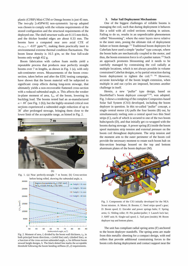
Boom fabrication with carbon foam molds yield a
repeatable process that produces near perfectly straight
booms over 7 m lengths, as shown in Fig. 1 (a), with only
sub-centimeter errors. Measurements of the boom cross-
section, taken before and after the EDU testing campaign,
have shown that the boom material will be subjected to
significant creep effects during long-term stowage, that
ultimately yields a non-recoverable flattened cross-section
with a reduced subtended angle, α. This affects the weaker
in-plane moment of area, Iyy, of the boom, lowering its
buckling load. The booms tested had an as-manufactured
α = 80° (see Fig. 1 (b)), but the highly-strained critical root
sections experienced a subtended angle reduction of up to
30° after prolonged stowage, bringing them close to the
lower limit of the acceptable range, as hinted in Fig. 2.
(a)
(b)
Fig. 1. (a) Near perfectly-straight 7 m boom; (b) Cross-section
before being rolled, showing the subtended angle, α.
Fig. 2. Moment of area, I, divided by the boom wall thickness, tsh, in both principal boom directions, x (solid line) and y (dashed line), as
a function of the cross-section subtended angle, α, for different boom
stowed height designs, h. The black dotted line marks the acceptable threshold following the boom bending stiffness (E11I) requirements.
3. Solar Sail Deployment Mechanisms
One of the biggest challenges of rollable booms is
managing the coil, such that during deployment it behaves
like a solid with all coiled sections rotating in unison.
Failing to do so, results in an unpredictable phenomenon
called “blossoming”, where the outer layers move relative
to the inner ones, posing the ultimate risk of deployment
failure or boom damage.11) Traditional boom deployers for
CubeSats have used a simple “pusher” type concept, where
the boom hubs are mechanically coupled to the motor, and
thus, the boom extension force is of a pusher nature.12) Such
an approach promotes blossoming and it needs to be
carefully managed by constraining the coil radially at
multiple locations, which is not always possible in volume
constrained CubeSat designs, or by partial retraction during
boom deployment to tighten the coil.13, 14) However,
accurate knowledge of the boom length extension, when
multiple in and out cycles are imposed, becomes another
challenge in itself.
Herein, a new “puller” type design, based on
DeorbitSail’s boom deployer concept15,16), was adopted.
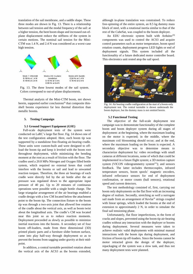
Fig. 3 shows a rendering of the complete Composites-based
Solar Sail System (CS3) developed, including the boom
deployer in question. In this so-called “puller” concept, a
single central motor (A) pulls the four booms (B) out, by
simultaneously reeling onto a central spool two thin Steel
strips (C), each of which is secured to one of the two boom
hubs/spools (D), and that initially get co-wrapped with the
booms during stowage. A power spring (E) inside the boom
spool maintains strip tension and external pressure on the
boom coil throughout deployment. The strip tension and
the moment arm to the outer perimeter of the boom coil
provide the necessary moment to rotate each boom hub on
thin-section bearings housed on the top and bottom
aluminum plates of the boom deployer (M).
Fig. 3. Components of the CS3 initially developed for the NEA
Scout mission. A: Motor; B: Booms; C: Steel strips spool’s gear;
D: Boom spool; E: Encoder and power springs hubs; F: Spring
arms; G: Sliding roller; H: Pin pusher/puller; I: Launch lock bar;
J: AMT unit; K: Single-sail spool; L: Sail post (inside); M: Boom
deployer top and bottom plates.
The unit has compliant radial spring arms (F) anchored
to the boom deployer standoffs. The spring arms are made
from thin metallic sheeting for a compact design, with end
rollers that provide additional constraining forces to the
boom coils during deployment and contact support near the
M
α
7 m
X
Y
Page 3
attachment points after deployment. Also, a series of fixed
and spring-loaded sliding rollers (G) provide lateral support
to the booms away from its clamped root. The boom hubs
have omega-shaped cut-out sections and spring-slider
connections for boom attachment to facilitate full recovery
of the boom cross-section once completely deployed. A
miniature pin pusher/puller (G), custom-made by Glenair
Inc.,1 fixed to a long lock/release bar mechanism (H)
engages cog features on the two boom spools and the Steel
strips spool. This is used as a launch lock system and after
the booms are deployed to prevent further spool rotation.
In order to provide attitude control to the sailcraft, a
two-axis active mass translation system (AMT), that
follows the same center of pressure to center of mass (CP-
CM) offset method to that of the Surrey Space Center’s
Translation Stage Unit (TSU) for CubeSail17,18), has been
developed by NASA Marshall Space Flight Center
(MSFC). This is shown as (J) on Fig. 3. It will allow relative
planar movement between the top and bottom halves of the
spacecraft to provide the necessary trimming of the sail.
The single-sail spool (K) design depicted in Fig. 3
corresponds to the one from NEA Scout’s single-square sail
configuration. This oval-shaped spool will rotate with
respect to the fixed inner sail post (L) to unfurl the sail
membrane. In this configuration, the single-square sail is
only supported at its four vertices and tensioned through
linear springs connected to the four boom tips. However,
the new Advanced Composites-based Solar Sail System
(ACS3) design proposed herein, uses a four-quadrant sail
configuration, as originally intended for NEA Scout, which
generates less asymmetric boom loads during deployment
with a more deterministic load path. Fig. 4 shows the twin-
spool design adopted, where two quadrants are Z-folded
along one direction and wrapped around each sail spool for
stowage. A central post still provides structural support and
serves as a cable feed-through port. Each triangular sail
quadrant will be supported from its two adjacent boom tips
and tensioned at the vertex near the spacecraft by a
purposely-designed retractable lanyard unit (C). This will
use a power/clock spring that sits below the sail spools and
provides a nearly constant force independent of spring
deflection and changing environmental conditions. Both
the lanyards and the sail spools are allowed to rotate while
the sail is unfurling, but towards the end of deployment, the
lanyards leave the sail spool slots and finally lock into
position when the quadrants are tensioned.
Fig. 4. Preliminary four-quadrant sail spool design for the ACS3.
A: Dual-sail spools; B: Sail post; C: Two lanyard system per spool.
1 https://glenair.com/hold_down_release_mechanism_technology/index.htm
In order to compactly stow the booms, additional
components were added to the boom deployer and removed
upon completion. Fig. 5 shows the ground support
equipment (GSE) used for this. An additional aluminum
plate (A) with radial slots (B) is first offset from the boom
deployer top plate by spacers (C). This allows radial spring-
loaded (D) sliding rollers (E) to be added, which provide
additional pressure to the coil during stowage to increase
the packaging efficiency. During the coiling process,
0.5 mm thick shims (not shown here) are also temporarily
added radially to the top and bottom plate to guarantee a
more uniform final height of the coil, which ultimately
reduces friction and abrasion during deployment. Hex rods
(F) are then coupled to the boom spools by the hex-shaped
holes of the latter. These rods act like shafts, that ultimately
get manually cranked using a ratchet wrench. Reaction
against the moments generated during the coiling process
is provided by placing the deployer in a frame with several
vertical bolts (G) accordingly spaced. Since the two boom
hubs are free to rotate independently, in order to keep both
steel tapes (H) tensioned during packaging, the shafts are
coupled by a gear train. Sometimes, when enough friction
in the system built up, as the diameter of the coil increased,
the lead gear (I) slipped with respect to the trail gear (J),
loosening the correspondent steel tape. It was then
necessary to remove the idler gear (K) to decouple the
larger gears and rotate the trailing spool the amount needed.
Fig. 5. Boom deployer GSE components for efficient boom packaging.
A: Additional plate; B: Radial slots; C: Spacer standoffs; D: Radial
linear springs; E: Radial sliding rollers; F: Hex shafts; G: Reaction
frame (bolts); H: Steel strip; I: Lead gear; J: Trail gear; K: Idler gear.
4. Structural Analysis
The Mini-CTM booms were analyzed in the context of
the NEA Scout mission (i.e. for a single square sail
configuration) and in comparison with metallic Elgiloy
TRAC5) booms. Under the criteria of NEA Scout, the two
boom systems had similar structural performance.
Because the sail membrane tension is an important
parameter for reflectivity and performance, the first goal of
structural analysis was to establish a guideline for sail
tension. There is a limit on the maximum sail tension that a
given set of booms can maintain without buckling or taking
an unacceptable shape. The second goal of the analysis was
to identify the normal modes of the sail for the
consideration of the attitude control team.
Page 4
Abaqus/Standard19) is used to build a model of the sail
system, shown in Fig. 6, with a detailed representation of
the sail booms. The booms were each modeled with 68520
S4R shell elements and the sail membrane was modeled as
a single square M3D4R membrane element.
Fig. 6. A wide view of the sail system model.
The root condition included rigid models of two parts
of the sail deployer: the boom spools and the sliding rollers.
Contact conditions were enforced between the booms and
both the spools and rollers. Additionally, a displacement
condition enforced the connection between the booms and
spools at two points on each boom root, as shown in Fig. 7.
At the boom tip, the connection to the sail membrane
was modeled with a simple spring and a rigid body that
represented the boom tip fitting. This is depicted in Fig. 8.
Fig. 7. The boom root conditions of the sail system model. Contact
between the boom and the spools was also included in the model.
Fig. 8. The connection between the boom tip and sail membrane
corners in the sail system model.
Two measures of global stiffness were used for the sail
system: “windmill angle,” illustrated in Fig. 9, and out-of-
plane displacement, illustrated in Fig. 10. These are simple
descriptions of the sail shape that capture the way it
changes in response to tensioning of the sail. Tensioning
was accomplished in the model by shortening the connector
elements that link the sail corners to the boom tips.
Fig. 11 and Fig. 12 show how the sail shape changes
with changes in the sail tension. Windmill angle and out-
of-plane displacement both increase with increasing
tension of the system, and the system becomes softer in out-
of-plane displacement as tension increases. The composite
mini CTM boom system was slightly softer than the
metallic TRAC boom system in out-of-plane sail
displacement, reflecting the lower stiffness of the
composite cross-section in bending. Both boom systems
provided an acceptable range of membrane tensioning, and
a nominal sail tension of 1.4 N for the Mini-CTM system
was selected, with analysis supporting some margin for
higher tension.
Fig. 9. Global windmill displacement/rotation of the sail system
relative to the spacecraft bus.
Fig. 10. Out-of-plane displacement of the sail system relative to the
spacecraft bus.
Fig. 11. Windmill displacement vs. sail membrane tensioning spring load.
Fig. 12. Out-of-plane displacement vs. sail membrane tensioning
spring tension.
Modal analysis showed that the three lowest modes of
the structure are a windmilling motion, an in-plane
Page 5
translation of the sail membrane, and a saddle shape. These
three modes are shown in Fig. 13. There is a relationship
between sail tension and the modal frequency of the sail: at
a higher tension, the bent boom shape and increased out-of-
plane displacement reduce the stiffness of the system in
certain motions. The nominal sail tension for the Mini-
CTM was 1.4 N, and 2.4 N was considered as a worst-case
high tension.
Fig. 13. The three lowest modes of the sail system.
Colors correspond to out-of-plane displacements.
Thermal analysis of the Mini-CTM boom, not shown
herein, supported earlier conclusions6) that composite thin-
shell booms experience far less thermal distortion than
metallic booms.
5. Testing Campaign
5.1 Ground Support Equipment (GSE)
Full-scale deployment tests of the system were
conducted on LaRC’s large flat floor. Fig. 14 shows one of
the test configuration adopted. Here, each boom tip was
supported by a standalone free-floating air-bearing cradle.
These units were custom-built and were designed to off-
load the boom tip and keep it leveled with the boom root
throughout deployment, while minimizing the bending
moment at the root as a result of friction with the floor. The
cradles used a 20.8 MPa Nitrogen and Oxygen filled bottle
system, which required no external hoses that could
interfere with the booms or sail and lead to unwanted
reaction torques. Therefore, the three air bearings of each
cradle were directly fed by the air bottle after the air
pressure was regulated down to the appropriate input
pressure of 40 psi. Up to 20 minutes of continuous
operations were possible with a single bottle charge. The
large triangular arrangement of the air bearings enabled a
cradle design with a low CM located below the attachment
point to the boom tip. The connection fixture to the boom
tip was through a two-axis joint that allowed free rotation
of the cradle about the vertical axis, as well as boom twist
about the longitudinal axis. The cradle’s CM was located
near this joint so as to reduce reaction moments.
Deployment proceeded as slowly as possible to minimize
inertial reactions into the booms. A secondary set of four
boom off-loaders, made from three dimensional (3D)
printed plastic parts and a furniture slider bottom surface,
came into play half-way through deployment so as to
prevent the booms from sagging under gravity at their mid-
point.
In addition, a central turntable permitted rotation about
the vertical axis of the ACS3 as the booms extended,
although in-plane translation was constrained. To reduce
free-spinning of the entire system, an 8.5 kg dummy mass
block of steel, with a rotational inertia similar to that of the
rest of the CubeSat, was coupled to the boom deployer.
An EDU electronic system built with Arduino20)
components was used to control the ACS3 and acquire
control parameters such as motor temperature, boom spool
rotation counts, deployment progress LED lights or end of
deployment signals. This system included all the
functionality of a future dedicated motor controller board.
This electronics unit rested atop the sail spool.
Fig. 14. Air bearing cradle configuration at the start of a boom-only deployment test. The central turntable is shown underneath the
boom deployer, but the dummy mass is not omitted herein.
5.2 Functional Testing
The objective of the full-scale deployment test
campaign was to demonstrate functionality of the complete
boom and boom deployer system during all stages of
deployment: at the beginning, where the maximum loading
on the motor is expected; in the middle, where the
maximum coil blossoming should occur; and at the end,
where the maximum loading on the boom is expected. A
secondary objective was to determine means to
characterize deployment by: video recordings with small
cameras at different locations, some of which that could be
implemented in a future flight system; a 3D motion capture
system (VICON videogrammetry system21)); and sensors
feedback. The latter includes thermocouples, infrared
temperature sensors, boom spools’ magnetic encoders,
infrared reflectance sensors for end of deployment
confirmation, or motor counts (hall sensors), rotational
speed and current detectors.
The test methodology consisted of, first, carrying out
boom only deployments on the flat floor with an increasing
degree of realism. Secondly, stretching as well a surrogate
sail made from an arrangement of Kevlar® strings coupled
with linear springs, which loaded the booms at the end of
extension to approximately 2 N, in order to simulate the
final sail tensioning phase.
Unfortunately, flat floor imperfections, in the form of
cracks and slopes, prevented using the boom tip air-bearing
cradles without any interaction with the deployer or booms
during deployment. Several measures were taken to
achieve realistic valid deployments with minimal manual
interactions with the boom tips during deployment, and
friction of boom tip off-loaders. Since the booms cannot be
motor retracted given the design of the deployer,
repackaging of the system was a slow task, and thus not
many deployment tests were planned.
Page 6
Table 1 shows the deployment test matrix carried out
and the GSE configuration arrangement followed for each
test. The first two tests were carried out with a fixed boom
deployer (i.e. not allowed to rotate) and furniture sliders at
the boom tips, as well as the boom mid-length points for
the case of Test 2. These tests were successful and proved
that the boom deployment mechanism worked flawlessly.
For Test 3, the air-bearing cradles and the turntable were
introduced (see Fig. 14). It was then, when the slopes on
the “flat-floor” were discovered. Test 4 went back to using
boom tip furniture sliders, but implemented the turntable
and a dummy mass to minimize system rotation, and thus,
lateral friction on the boom tips that could lead to buckling.
Test #
/ GSE Configuration
1 2 3 4 5 6 7 8
Fixed Deployer x x x x x
Turntable x x x
Dummy Mass x x
Middle Furniture Sliders x x x x x x x
Tip Furniture Sliders x x x
Air-Bearing Cradles x x x x x
Teflon® Floor Tracks:
(s) - straight; (c) - curved
x
(s)
x
(s)
x
(c)
Hand-Guided x x x
Sail Surrogate x x x
Table 1: Full-scale deployment test plan with GSE arrangement.
In order to be able to use the air bearings, which would
provide more realistic loading conditions during the critical
final stage of deployment (sail tensioning), low-friction
tracks made from 6 mm Teflon® rods were taped to the
floor to guide the cradles. For Test 5, a straight four-lane
floor track lay-out with a free-to-spin boom deployer at the
center was arranged. Friction with the tracks forced the
deployer to rotate, as the boom exit angle needs to change
during deployment given the reduction in boom coil size
and the fixed exit rollers used. For Test 6, the booms were
partially re-coiled and the sail surrogate was added. This
was the first sail-like tensioning test and only consisted of
extending out the booms 30 cm until the springs loaded
them appropriately. For Test 7, the deployer was fixed, and
thus, curved floor tracks were laid-out to account for the
continuous change in boom tip direction, as shown in
Fig. 15 points of the ideal curves were determined with
computer aided design (CAD) tools and marked on the
floor, with the aid of laser, prior to taping the flexible
Teflon® rods. This test was the first end-to-end deployment
test, but required interaction with the cradles due to them
catching on floor and track defects. For the last test (#8),
the floor tracks were removed and the cradles were
manually redirected to the correct path once they started
drifting due to the floor slopes and cracks.
As a result of the various successful tests, it was
determined that the deployment mechanisms and booms
performed well during all phases of deployment, and that
the booms could be loaded to the required levels.
Therefore, it was concluded that continuing to battle an
imperfect floor to achieve an ideal set of boundary
conditions was not deemed necessary at that point, and thus
further testing would resume when the flat floor was
repaired or another similar facility would be available.
(a) (b)
Fig. 15. (a) Boom deployer view of deployment Test 7 with the
curved floor tracks; (b) Boom tip air-bearing cradle inside the floor
track showing several infrared (IR) markers and the bow tie targets.
Fig. 16 shows the motor feedback parameters obtained
during Test 5. The motor angular velocity input profile
adopted consisted of a three step function: the initial 10%
of the motor counts (deployment) at a 3000 rpm speed; the
following 80% at 7500 rpm; and the final 10% at 3000 rpm,
so as to not overload the motor during the critical stages of
deployment (start and end). For all deployment tests, the
motor torque margin was always ≥ 2, as the maximum
current observed was approximately 0.5 A, and the
maximum allowed by the motor is 1 A. As can be seen from
the graph, the motor current reduces over time from 0.3-
0.35 A to 0.2 A, since friction inside the deployer reduces
as the size of the boom coil diminishes. The current spike
at the end of deployment, that reaches up to 0.5 A, is due to
tensioning the sail surrogate. Lower current values were
obtained on subsequent tests as the boom packaging
efficiency was improved with the redesigned metallic GSE
shown in Fig. 5. The exact motor counts for this particular
test were 94294, which translates to about 255 turns of the
tape spool or about 30.5 turns of the boom spools.
Fig. 16. Test 5 deployer motor performance.
Deployment Rate Tracking
The deployment trajectories of the four air-bearing
cradles connected to the boom tips and motion of the boom
deployer were measured using videogrammetry equipment.
This technique provides simultaneous motion knowledge
of several targets as they deploy. The Vicon® system with
a set of eight Bonita B3 cameras shooting at 240 frames-
IR ball
targets
Bow tie
targets
Page 7
per-second was used with the Vicon® Tracker 3.2 data
acquisition and post-processing software package. The
arrangement of the cameras was such that, at least, three
could track each boom tip throughout deployment. Each
air-bearing cradle and the electronic board atop the boom
deployer were equipped with five 25 mm diameter
retroreflective infrared (IR) markers in a random 3D
arrangement created by different length wooden sticks
fixed to the targets. The centroid of the different 3D objects
created by the IR markers was then tracked by the IR
cameras, providing all six degrees of freedom
displacements (three translations and three rotations).
Linear and angular velocity and acceleration of the targets
are also readily available by a simple time derivate of
position knowledge. Additional bow tie sticker targets were
added to the cradles to provide a less accurate redundant
two dimensional (2D) motion tracking system by an
overhead optical camera that took pictures every 5 seconds
(photogrammetry). Fig. 15 shows some of the different
targets at the boom deployer and at a boom tip air-bearing
cradle.
Fig. 17 presents the translation, T, of the boom tip in all
three axes during Test 3 for Boom 1 and Boom 2, which
were aligned with the +Y and –X global axes, respectively.
It is shown that boom deployment speed was not constant,
which is in line with the motor rotation stepped profile
adopted. As expected, it was a 2D planar deployment with
negligible Z axis translation (Tz remains constant).
Fig. 17. Test 3 boom tip motion for Boom 1 (+Y) and Boom 2 (-X).
It can also be seen that floor defects prevented a
nominal deployment, as it required half-way through the
test, several manual interventions in the +Y direction to
correct the course of Boom 2. This example is presented to
showcase that boom tip position data can be useful to track
causes of deployment anomalies, and, in this case, even
evaluate floor topography. This was a shorter than usual
test, in part initially devised to assess the run time of the
air-bearing cradles. As shown, the bottles ran out of gas
prematurely stopping the test about 0.9 m from the end of
deployment planned. The air bearing input pressure was
then reduced for future tests, from the nominal 60 psi to an
experimental minimum working pressure of 40 psi, in order
to extend the run time of the units and enable at least 20
min long tests. Slowing the deployment process reduces
inertial effects and dynamics, as well as motor loading, so
it is advisable. The real in-space operation might even
proceed slower than this, if deemed necessary.
Fig. 18 shows the boom deployer rotation about the out-
of-plane Z axis during Test 4. As the motor and boom
spools rotate in a clockwise (+Z) manner and the whole
system is free to spin on a turntable (simulating the in-space
condition), the reaction torque causes the system to spin
counter-clockwise. This is evident from the graph, where
the Rz rotation angle decreases over time. During extension,
the boom tips follow a curve similar to that shown in
Fig. 15 (a), with a counter-clockwise spiral motion until the
very last stages where the curvature changes to a clockwise
motion. However, lateral friction of the furniture slider off-
loaders with the floor causes a momentum build-up at the
boom root. In Fig. 18, the abrupt -30° rotation observed is
caused by the deployer system self-aligning with the new
boom tip direction following the principle of minimum
energy. The change in spin direction at the end of
deployment, when the boom roots fully develop and lock
into place, produces a clockwise rotation of about +17°,
with a final total rotation of +10° as the deployer settles.
Knowledge of the relative motion of the spacecraft hub
with respect to the unfurling solar sail is important to avoid
boom root buckling during deployment, as well as to size
the controller that will need to dampen any unwanted
remaining rotational rates of the sailcraft following
deployment.
Fig. 18. Test 4 boom deployer rotation about the vertical Z axis.
5.3 Environmental Testing
The environmental testing campaign carried out on the
CS3 unit was conceived in the context of the NEA Scout
mission. Four main tests were carried out: vibration testing
following the Exploration Mission 1 (EM-1) preliminary
launch load environment of the Space Launch System
(SLS) with subsequent post-vibe complete boom
deployment; Thermal (cold) - vacuum acceptance test of
the deployer motor and tape heater units alone; Partial
boom-only deployment test under thermal (hot) and
vacuum conditions; Partial boom-only deployment testing
under thermal (cold) and vacuum conditions with
subsequent ambient complete boom deployment.
Vibration Test
The objective of the vibration test was to assess the
survivability of the CS3 sub-unit, which included the boom
deployer, full-scale coiled booms, and the sail spool with a
dummy folded/rolled single-square Mylar® sail, to the
expected launch environment. Visual inspections between
Page 8
each test axis included: fastener loosening, changes in
boom coil diameter, changes in clearances between boom
coils and the top/boom deployer plates, configuration of the
locking mechanism, loosening of bearings, loosening of the
motor, disengagement or misalignment between drive
gears, and any other visible damage.
Fig. 19 shows the test configuration adopted for the Z
axis vibration tests. Two triaxial control accelerometers
were mounted to the upper and lower fixture steel blocks
and used as feedback to the shaker controller. These heavy
blocks are used to stiffly secure the CS3 unit to the 30 cm
magnesium block, that ultimately bolts down to the shaker
table. Two triads of single-axis response accelerometers
(ACC1 and ACC2) oriented in the principal X, Y and Z
axes were fixed to the upper and lower plates inside the
deployer.
Fig. 19. Z axis vibration test setup showing the location of the two
controls and one of the response (ACC1) accelerometers. The
yellow dashed line ellipses show the lower fixture block standoffs.
Table 2 shows the vibration test matrix followed. The
Maximum Predicted Environment (MPE) for the random
vibration testing implemented, in terms of acceleration
spectral density (ASD) was:
0.1 g2/Hz in the 20-100 Hz range.
Ramp down to 0.04 g2/Hz at 150 Hz.
0.04 g2/Hz in the 150-500 Hz range.
Ramp down to 0.01 g2/Hz at 2000 Hz.
This adds up to 7.2 grms, and 10.1 grms for the MPE +3dB
levels actually used.
Axis Test Level Duration/R
ate
Z, X, Y
(repeated for
all 3 axes)
Signature Sine Sweep 0.25 gpk 4
octave/min
Random Vibration
(MPE +3dB)
10.1 grms 3 min
Signature Sine Sweep 0.25 gpk 4
octave/min
Visual Inspection N/A N/A
N/A Deployment Test N/A N/A
Table 2. Vibration test matrix with the levels and durations/rates used.
The stowed CS3 unit showed no signs of visible
damage or alteration during vibration testing. Fig. 20
shows, as an example, the Z axis random acceleration
spectral input and the response of two uniaxial
accelerometers in that same axis. Pre and post-vibration
sine sweeps showed small differences at mid/high
frequencies due to the loosening of the lower fixture block
mounting standoffs/screws. Fig. 21 shows the Y axis sine
sweep input and response of the ACC1-Y accelerometer. It
can be seen that the first pre-vibe global mode at ~450 Hz
split into two modes after the Y axis random vibration test.
This is probably due to some flexibility induced in the test
unit that allowed the top part to move with respect to the
bottom part. Some other smaller variations at higher
frequencies are also evident. The location of these
standoffs/screws is shown in Fig. 19. These components do
not form part of the CS3 unit and are just there to offset the
deployer from the fixture block in order to clear off some
of the protruding deployer elements. These series of
development vibration tests will be redone once the final
SLS’s MPE loads are available. Proper fixing of the lower
fixture block through stiffer connectors will also be
guaranteed.
The post-vibration boom only deployment test
proceeded nominally on all fronts with no signs of damaged
or displaced components. The motor current output data
were also nominal.
Fig. 20. Z axis random vibration spectral input and response of the
ACC1-Z and ACC2-1 accelerometers.
Fig. 21. Y axis sine sweep input and response of the ACC1-Y
accelerometer before and after the Y axis random vibration test.
Thermal-Vacuum Test: Deployer Motor & Heater
A development thermal-vacuum (TVAC) cold test on
the deployer motor and heater was conducted to gain
confidence on the components prior to testing the complete
Page 9
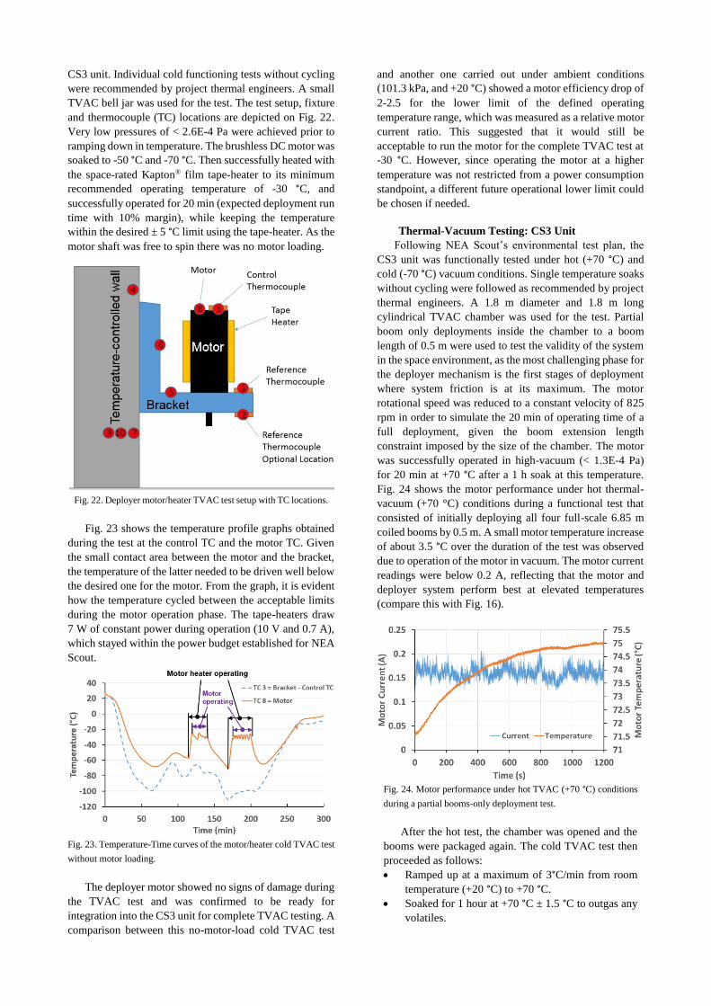
CS3 unit. Individual cold functioning tests without cycling
were recommended by project thermal engineers. A small
TVAC bell jar was used for the test. The test setup, fixture
and thermocouple (TC) locations are depicted on Fig. 22.
Very low pressures of < 2.6E-4 Pa were achieved prior to
ramping down in temperature. The brushless DC motor was
soaked to -50 °C and -70 °C. Then successfully heated with
the space-rated Kapton® film tape-heater to its minimum
recommended operating temperature of -30 °C, and
successfully operated for 20 min (expected deployment run
time with 10% margin), while keeping the temperature
within the desired ± 5 °C limit using the tape-heater. As the
motor shaft was free to spin there was no motor loading.
Fig. 22. Deployer motor/heater TVAC test setup with TC locations.
Fig. 23 shows the temperature profile graphs obtained
during the test at the control TC and the motor TC. Given
the small contact area between the motor and the bracket,
the temperature of the latter needed to be driven well below
the desired one for the motor. From the graph, it is evident
how the temperature cycled between the acceptable limits
during the motor operation phase. The tape-heaters draw
7 W of constant power during operation (10 V and 0.7 A),
which stayed within the power budget established for NEA
Scout.
Fig. 23. Temperature-Time curves of the motor/heater cold TVAC test
without motor loading.
The deployer motor showed no signs of damage during
the TVAC test and was confirmed to be ready for
integration into the CS3 unit for complete TVAC testing. A
comparison between this no-motor-load cold TVAC test
and another one carried out under ambient conditions
(101.3 kPa, and +20 °C) showed a motor efficiency drop of
2-2.5 for the lower limit of the defined operating
temperature range, which was measured as a relative motor
current ratio. This suggested that it would still be
acceptable to run the motor for the complete TVAC test at
-30 °C. However, since operating the motor at a higher
temperature was not restricted from a power consumption
standpoint, a different future operational lower limit could
be chosen if needed.
Thermal-Vacuum Testing: CS3 Unit
Following NEA Scout’s environmental test plan, the
CS3 unit was functionally tested under hot (+70 °C) and
cold (-70 °C) vacuum conditions. Single temperature soaks
without cycling were followed as recommended by project
thermal engineers. A 1.8 m diameter and 1.8 m long
cylindrical TVAC chamber was used for the test. Partial
boom only deployments inside the chamber to a boom
length of 0.5 m were used to test the validity of the system
in the space environment, as the most challenging phase for
the deployer mechanism is the first stages of deployment
where system friction is at its maximum. The motor
rotational speed was reduced to a constant velocity of 825
rpm in order to simulate the 20 min of operating time of a
full deployment, given the boom extension length
constraint imposed by the size of the chamber. The motor
was successfully operated in high-vacuum (< 1.3E-4 Pa)
for 20 min at +70 °C after a 1 h soak at this temperature.
Fig. 24 shows the motor performance under hot thermal-
vacuum (+70 °C) conditions during a functional test that
consisted of initially deploying all four full-scale 6.85 m
coiled booms by 0.5 m. A small motor temperature increase
of about 3.5 °C over the duration of the test was observed
due to operation of the motor in vacuum. The motor current
readings were below 0.2 A, reflecting that the motor and
deployer system perform best at elevated temperatures
(compare this with Fig. 16).
Fig. 24. Motor performance under hot TVAC (+70 °C) conditions
during a partial booms-only deployment test.
After the hot test, the chamber was opened and the
booms were packaged again. The cold TVAC test then
proceeded as follows:
Ramped up at a maximum of 3°C/min from room
temperature (+20 °C) to +70 °C.
Soaked for 1 hour at +70 °C ± 1.5 °C to outgas any
volatiles.
Page 10
Ramped down at a maximum of 3°C/min to -70 °C.
Soaked for 1 hour at +70 °C ± 1.5 °C.
Ran the motor heaters to bring up the motor
temperature to -30 °C, stabilizing it to within ± 5 °C.
Deployed the four coiled 6.85 m booms by 0.45 m
in 17 min.
Fig. 25 shows the motor and motor heater performance
under cold thermal-vacuum (-70 °C) conditions during a
partial booms-only deployment test. The motor rotational
speed was further reduced to a constant velocity of 775 rpm
to simulate approximately 20 min of run time for a full
deployment. As shown, the motor was successfully
operated for 17 min, just a little short of the target, due to
one boom tip catching on a thermocouple wire. This was
observed in real time by the video camera held inside the
TVAC chamber. Deployment was then stopped remotely
so as to not damage the boom. On the whole, the test was
considered successful given the deployer performance
trend observed. Fig. 25 evidences that the motor heater and
its controller were capable of bringing up the motor
temperature to the desired -30 °C and hold it within ± 5 °C
by cycling the heater on and off, including system lagging.
As expected, the performance of the motor in the cold
conditions dropped. The motor current reached a maximum
of 0.6 A momentarily, but in general was lower than
0.5-0.55 A. The current is expected to decrease further as
deployment progresses. These test results provide
confidence that this motor and heater combination could be
used for flight with enough motor torque margin, even at
the motor minimum operating temperature limit of -30 °C
± 5 °C defined.
Fig. 25. Motor and motor heater performance under cold TVAC
(-70 °C) conditions during a partial booms-only deployment test.
The commercial-off-the-shelf (COTS) brushless DC
Maxon22) motor with added high-vacuum rated Braycote®
601E grease lubricant showed no signs of damage during
the TVAC testing campaign and could be considered for a
flight ACS3 unit. The final full-scale post-TVAC
deployment test under ambient conditions, that essentially
completed the rest of the partial deployment test of the cold
TVAC test, was nominal. The test configuration was
similar to that of Test 8 shown in Table 1 and was carried
out on the same flat floor.
6. Conclusions
A summary of the design and development of NASA
LaRC’s new Advanced Composites-based Solar Sail
System (ACS3) for future small satellite science and
exploration missions has been presented. The ultra-
lightweight scalable rollable booms made from state-of-
the-art thin-ply composite materials enables a scalable solar
sail design that can achieve a 10% higher characteristic
acceleration than current 6U CubeSat solar sail designs,
such as NEA Scout. Such a system will be a faster and more
agile (less rotational inertias) sailcraft, that can extend the
capabilities of these relatively low-cost and small solar
sails.
The boom deployer uses a novel “puller” type concept
to drive the booms, aimed at minimizing the known issue
of coil blossoming by design. A system of retractable
lanyards is introduced at the sail spools to yield a near
constantly-tensioned four-quadrant sail through all mission
phases. Removable GSE was designed to achieve very high
boom packaging efficiencies of about 85%, in order to fit
all four 6.85 m booms in the small volume available.
The structural analysis of the fully integrated solar sail
showed that, as for the case of a similar sail tensioned by
an Elgiloy TRAC boom system, the Mini-CTM composite
boom system provides an acceptable range of membrane
tensioning. The analysis predicts at least a 70% safety
margin over the nominal sail tension of 1.4 N adopted.
Modal analysis showed that the lower frequencies of the
tensioned sail system are within an acceptable limit, which
could be established at around 0.09-0.1 Hz, even for the
higher sail tensioning worse-case of 2.4 N. A thermal
analysis at boom component level, not shown herein, also
supports the conclusion that the composite boom
experiences far less thermal distortions than equivalent and
similar metallic booms, and is thus not a future mission risk
any more.
The ambient functional testing campaign of the boom
system, with a surrogate sail made with Kevlar® strings and
linear springs to simulate final sail tensioning, showed the
challenges of deploying on the ground such a gossamer
structure, particularly when working with an imperfect “flat
floor”. Given the various successful tests with minimal
manual interaction with the booms, it was determined that
the booms and deployer performed well, and that the booms
could be loaded at the end to the required levels. A 3D
videogrammetry system was successfully used to track the
deployment rates (i.e. boom tip displacement, speed and
acceleration, and deployer rotation, angular velocity and
acceleration), and help capture causes of deployment
anomaly. A final windmill rotation of the system due to the
booms locking into position was observed and will need to
be evaluated by the future attitude control team, which will
need to dampen the resultant angular rates of the sailcraft.
The CS3 unit survived the vibration testing campaign
without any signs of damage and the post-vibration
deployment test was nominal. However, some loosening of
GSE screws resulted in small differences in the mid/high
frequency between the pre and post-vibration sine sweeps.
Thermal-vacuum tests at hot (+70 °C) and cold (-70 °C)
conditions, that consisted of partial booms-only
Page 11
deployments inside the TVAC chamber, showed that the
various CS3 mechanisms, sensors, booms, deployer motor
and motor tape heater worked flawlessly. As expected, the
deployer motor performance dropped while running at its
recommended minimum operating temperature, but the
motor torque margin found is still acceptable.
All in all, the CS3 unit is ready to be part of an actual
mission and serve as the propellantless propulsion system
of a CubeSat-based sailcraft. Nonetheless, the ACS3, that
will use a four-quadrant sail configuration and slightly
taller 55-60 mm Mini-CTM/Omega booms (see Fig. 2),
would be the preferred future choice for a solar sail
technology demonstration mission. A current effort is also
examining scaled-up versions of the ACS3 for higher
performance and more capable solar sails systems aboard
small satellite platforms that would extend their usefulness.
For example, a preliminary design of a ~360 m2 sail area
ACS3 to be housed on a 12U CubeSat platform is presently
being studied by the LaRC team for possible near-to-mid-
term implementation. This solar sail spacecraft could
achieve a characteristic acceleration of ~0.15 mm/s2 at 1au.
Such a system would use larger 14 m class CTM/Omega
composite booms and four scaled-up boom deployers,
which are currently being developed under a parallel effort
as part of a Game Changing Development Program (GCDP)
project called “Deployable Composite Booms” funded by
the NASA Space Technology Mission Directorate (STMD).
Acknowledgements
This work is financially supported by NASA’s
Advanced Exploration System (AES) Program under the
Future Exploration Projects portfolio. The help from past
NASA interns, Charles White, Matthew Lee, David
Shekhtman, and Wayne Page, as well as from the
composite fabrication technicians, Jacob Tury and Kevin
McLain, is gratefully acknowledged.
References 1) Alhorn, D., et al., NanoSail-D: The Small Satellite That Could,
25th Annual AIAA/USU Conference on Small Satellites, Logan,
Utah, 2011, SSC11-VI-1.
2) Biddy, C., Svitek, T., LightSail-1 Solar Sail Design and
Qualification, 41st Aerospace Mechanisms Symposium,
Pasadena, California, 2012.
3) Ridenoure, R., et al., LightSail Program Status: One Down, One
to Go, 29th Annual AIAA/USU Conference on Small Satellites,
Logan, Utah, 2015, SSC15-V-3.
4) McNutt, L., et al., Near-Earth Asteroid Scout, AIAA SPACE
2014 Conference and Exhibition, San Diego, California, 2014,
AIAA 2014-4435.
5) Banik, J.A., Murphey, T.W., Performance Validation of the
Triangular Rollable And Collapsible Mast, 24th Annual
AIAA/USU Conference on Small Satellites, Logan, Utah, 2010,
SSC10-II-1.
6) Stolhman, O., Loper, E. R., Thermal Deformation of Very
Slender Triangular Rollable and Collapsible Booms, 3rd AIAA
Spacecraft Structures Conference, San Diego, California, 2016,
AIAA 2016-1469.
7) Fernandez, J.M., Advanced Deployable Shell-Based Composite
Booms For Small Satellite Structural Applications Including
Solar Sails, 4th International Symposium on Solar Sailing,
Kyoto, Japan, 2017.
8) Rennie, B.B., New Closed Tubular Extendible Boom, 2nd
Aerospace Mechanisms Symposium, ed: Herzl, G.G., JPL, TM
33-355, pp 163-170, 1967.
9) Herbeck, L., et al., Development and Test of Deployable Ultra-
Lightweight CFRP-Booms for a Solar Sail, European
Conference on Spacecraft Structures, Materials, and Mechanical
Testing, Noordwijk, The Netherlands, 2000.
10) Hillebrandt, M., et al., The Boom Design of the De-Orbit Sail
Satellite, 13th European Conference on Spacecraft Structures,
Materials and Environmental Testing, Braunschweig, Germany,
2014 (ESA SP-727, June 2014).
11) Hoskin, A., Blossoming of Coiled Deployable Booms, 56th
AIAA/ASME/ASCE/AHS/ASC Structures, Structural
Dynamics and Materials Conference, Kissimmee, Florida, 2015.
AIAA 2015-0207.
12) Fernandez, J.M., et al., Design and Development of a Gossamer
Sail System for Deorbiting in Low Earth Orbit, Acta
Astronautica, Vol. 103, 204-225, 2014.
13) Fernandez, J.M., et al., Deployment Mechanisms of a Gossamer
Satellite Deorbiter, 15th European Space Mechanisms &
Tribology Symposium, Noordwijk, The Netherlands, 2013.
14) Sobey, A.R., Lockett, T.R., Design and Development of NEA
Scout Solar Sail Deployer Mechanism, 43rd Aerospace
Mechanism Symposium, Santa Clara, California, 2016.
15) Stohlman, O., Fernandez, J.M., et al., Testing of the DeOrbitSail
Drag Sail Subsystem, 54th AIAA/ASME/ASCE/AHS/ASC
Structures, Structural Dynamics and Materials Conference,
Boston, Massachusetts, 2013. AIAA 2013-1807.
16) Meyer, S., Hillebrandt, M., et al., Design of the De-Orbit Sail
Boom Deployment Unit, 13th European Conference on Spacecraft
Structures, Materials and Environmental Testing, Braunschweig,
Germany, 2014.
17) Fernandez, J.M., et al., CubeSail: A Low-Cost Nano-Solar Sail
for Space Debris Reduction in LEO, 1st IAA Conference on
University Satellite Missions, Rome, Italy, 27-29 January 2011.
18) Lappas V.J., et al., CubeSail: A Low-Cost CubeSat Based Solar
Sail Demonstration Mission, Advances in Space Research, Vol.
48, Issue 11, 1890-1901, 2011.
19) Abaqus v. 6.13-3, Dassault Systèmes Simulia Corp., Providence,
RI, USA.
20) Arduino, www.arduino.org
21) Vicon, www.vicon.com
22) Maxon, www.maxonmotorusa.com