NASTRAN MODELING AND ANALYSIS OF RIGID AND FLEXIBLE WALLED ACOUSTIC CAVITIES Joseph A. Wolf, Jr., and Donald J. Nefske Research Laboratories General Motors Corporation Warren, Michigan SUMMARY The acoustic slot elements, CSLOTi, have been applied to analyze two- dimensional enclosures with fixed or moving boundaries. The capability has been utilized to compute (a) the acoustic natural modes and frequencies of I a rigid walled enclosure and (b) the sound pressure at any point inside an enclosure when the surrounding walls are forced to vibrate. Applications to an automobile passenger compartment illustrate the technique. The axisymmetric fluid elements, CFLUIDi, have been used in conjunction with a suitable choice of symmetry planes and a model of the surrounding structure to approximate a two-dimensional enclosure with flexible walls. The enclosure walls are modeled using finite elements or structural modes. Illustrative examples include a comparison of rectangular cavity modes with those calculated using the acoustic slot element and the free vibration modes of two enclosures coupled through a flexible rectangular panel. INTRODUCTION Modification of the NASA Structural Analysis (NASTRAN) program for connected slot acoustic analysis was first discussed by Herting et al. (Ref. i) at the 1971 NASTRAN Users' Colloquium. This capability was later included in NASTRAN, along with an axisymmetric hydroelastic model, as documented in the NASTRAN Theoretical and User's Manuals (Refs. 2 and 3). The capability provided for therein includes rigid or moving wall two-dimensional slot models and rigid, moving, or elastic wall axisymmetric models. The present paper describes some adaptations of this acoustic analysis capability which have not been described in the NASTRAN documentation, and it illustrates these adaptations through applications to some problems of practical interest. Examples include calculation of acoustic modes and frequencies for irregularly shaped cavities, calculation of frequency response for piston-like wall excitation of an acoustic cavity slot-model, use of axisymmetric hydroelastic elements to approximate a two-dimensional cavity I with flexible walls, and modeling of cavities coupled through flexible panels. The implementation is within the present NASTRAN framework and involves no i new elements or rigid format alterations. 615 https://ntrs.nasa.gov/search.jsp?R=19750023450 2018-06-19T00:18:43+00:00Z
Transcript
NASTRAN MODELING AND ANALYSIS OF RIGID
AND FLEXIBLE WALLED ACOUSTIC CAVITIES
Joseph A. Wolf, Jr., and Donald J. Nefske
Research Laboratories
General Motors Corporation
Warren, Michigan
SUMMARY
The acoustic slot elements, CSLOTi, have been applied to analyze two-
dimensional enclosures with fixed or moving boundaries. The capability has
been utilized to compute (a) the acoustic natural modes and frequencies of
I a rigid walled enclosure and (b) the sound pressure at any point inside an
enclosure when the surrounding walls are forced to vibrate. Applications to
an automobile passenger compartment illustrate the technique.
The axisymmetric fluid elements, CFLUIDi, have been used in conjunction
with a suitable choice of symmetry planes and a model of the surrounding
structure to approximate a two-dimensional enclosure with flexible walls. The
enclosure walls are modeled using finite elements or structural modes.
Illustrative examples include a comparison of rectangular cavity modes with
those calculated using the acoustic slot element and the free vibration modes
of two enclosures coupled through a flexible rectangular panel.
INTRODUCTION
Modification of the NASA Structural Analysis (NASTRAN) program for
connected slot acoustic analysis was first discussed by Herting et al. (Ref. i)
at the 1971 NASTRAN Users' Colloquium. This capability was later included
in NASTRAN, along with an axisymmetric hydroelastic model, as documented in
the NASTRAN Theoretical and User's Manuals (Refs. 2 and 3). The capability
provided for therein includes rigid or moving wall two-dimensional slot
models and rigid, moving, or elastic wall axisymmetric models.
The present paper describes some adaptations of this acoustic analysis
capability which have not been described in the NASTRAN documentation, and it
illustrates these adaptations through applications to some problems of
practical interest. Examples include calculation of acoustic modes and
frequencies for irregularly shaped cavities, calculation of frequency response
for piston-like wall excitation of an acoustic cavity slot-model, use of
axisymmetric hydroelastic elements to approximate a two-dimensional cavity
I with flexible walls, and modeling of cavities coupled through flexible panels.
The implementation is within the present NASTRAN framework and involves no
the hatchback type. The computed resonant frequencles and the nodal lines
£or the lowest four modes are shown in Figure 3 for the compartment completely
closed (for comparison, see similar computations reported in Refs. 4 & 5) andalso for the compartment with the hatch open. (An open portion of the boundary
can be modeled by applying single point constraints at the boundary GRIDS
points.) The modes shown in the figure are analogous to the modes which occur
in the tube except for the effects introduced by the irregular boundary shape.
_he open hatch configuration reduces the fundamental frequency, analogous to
Fhat occurs when one end of the closed-closed tube is opened, although inthis case the fundamental frequency is not halved as it is for the tube. The
figure shows some comparisons of the computed frequencies with experimentallyDbtained frequencies, and the agreement can be seen to be quite favorable.
DIRECT FREQUENCY RESPONSE
Rigid Format number 8 -- Direct Frequency and Random Response -- can be
_sed to compute the sound pressure at the gridwork of points of the finite
element model, for prescribed vibration input at the boundary. This capability,
while not described in detail in the NASTRAN documentation, is alluded to on
_. 1.9-2 of the User's Manual (Ref. 3) by the statement, "Dynamic load cards
.t . . may be introduced to account for special effects." Here the use of the
RLOAD2 card with the slot-elements is described for the purpose of making
direct frequency response computations of the acoustic sound pressure inside
an enclosure.
The complete list of bulk data cards which are required includes:
Card
AXSLOT
GRIDS
CSLOT3, CSLOT4
RLOAD2
DAREA
DPHASE
FREQI
TABLED4
Purpose
parameter definition
scalar point specification
element definition
boundary condition specification
vibration modeshape specification
vibration phase specification
vibration frequency specification
vibration type specification
To prescribe a vibration of the boundary, the RLOAD2 card is used to specify
DAREA and DPHASE cards which are applied directly to the GRIDS points de-
fining the boundary. The DAREA cards specify the modeshape of the vibration,
nd the DPHASE cards specify the phase of the vibration. The FREQI card
etermines the frequencies at which the computations are made, and the TABLED4
ard specifies the type of modeshape (i.e., acceleration or displacement) being
617
input. Specifying only a constant on the TABLED4 card indicates an accelera-
tion modeshape, and specifying only an f2 dependence (f = frequency) indicat_
a displacement modeshape.
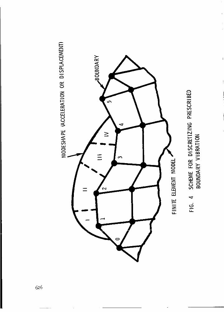
Figure 4 illustrates the scheme which has been used for discretizing th
modeshape for preparing the DAREA cards. The scheme lumps the area in regio
I on the DAREA card for GRIDS point i, the area in region II on the DAREA ca
for GRIDS point 2, etc., where the areas are defined by the bisectors of the
distances between the points. For this scheme, width = i is assumed to be
specified on the AXSLOT card.
Figure 5 shows a typical application of this capability to compute the
sound pressure inside an automobile passenger compartment when the back wind
shield is vibrating in a prescribed modeshape with a prescribed acceleration
The figure illustrates the application which involves computing the pressure
PA at point A when a half-sine acceleration modeshape is prescribed. The
response at A as a function of panel frequency _ can be obtained, and a plot
of the solution is also shown in the figure. The frequencies fl, f2, f3'at which the response becomes infinite are the acoustic resonant frequencies
of the compartment which can be computed as described above under "Normal
Modes Analysis."
ACOUSTIC FINITE ELEMENT MODELING WITH THE
CFLUIDi ELEMENT -- APPROXIMATION OF PLANE PROBLEM
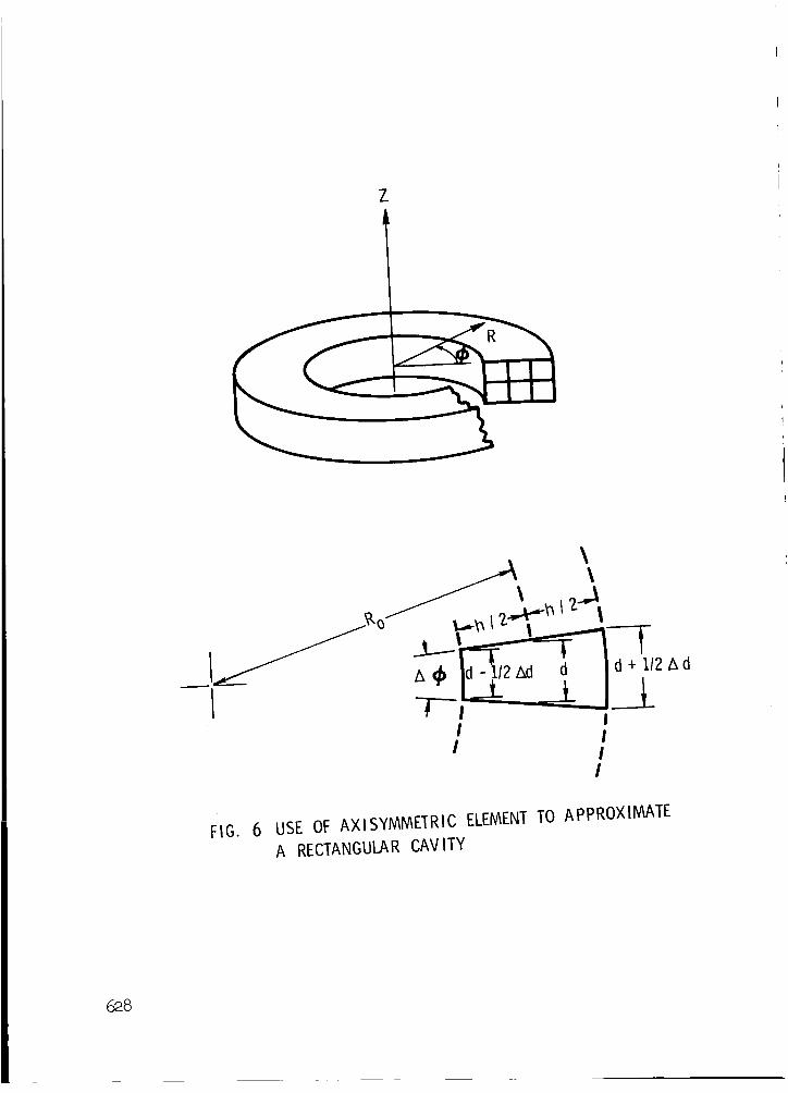
In addition to possessing the rigid and moving boundary modeling capabi
ities of the slot element, the axisymmetric element may be connected to
structural elements to provide flexible boundary models. By a judicious chc
of overall geometry and of fluid symmetry planes, the CFLUIDi elements may I
used to approximate a two-dimensional cavity and thus provide a flexible
wall capability not otherwise available in NASTRAN. Referring to Figure 6,
we see that if the radius Ro is sufficiently large, and the angle A_ is sufJ
ciently small, the resulting thin slice can be made as close to a cavity of
uniform depth as desired. The fractional difference in depth, Ad/d, is giw
by h/Ro. Thus for a cavity depth variation of ± 1% from nominal, one would
select R o = 50 h. To complete the two-dimensional analogy, one assumes thal
the fluid motion normal to the cross section is negligible compared with th_
in-plane components. In the NASTRAN model, this is accomplished by selectil
a NOSYM value of NO, and including only N1 = 0 (zeroth harmonic) in the har-
mollie LLumbers for _v_w.--1--__. _h_.._....AYTW_ard. To correctly model the intera_
tion terms, a FLSYM card is included, with an even integer, M = 360°/A_, an_
S1 = S2 = S.
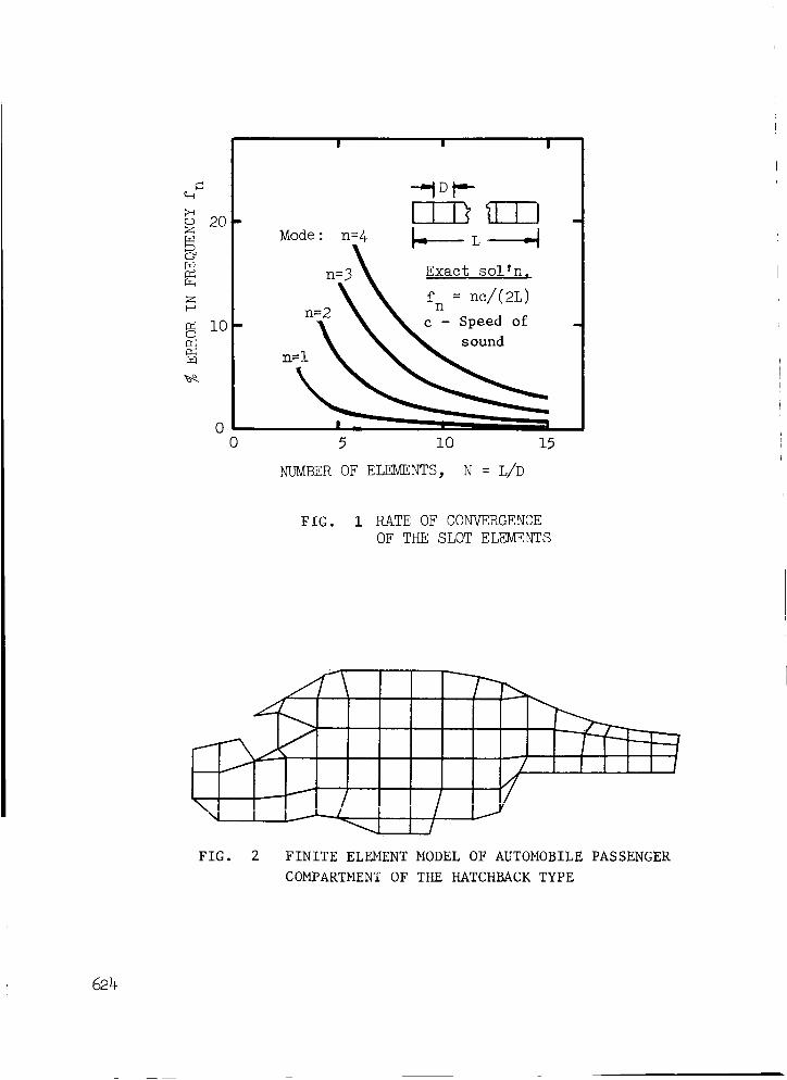
The influence of the out-of-plane curvature on the acoustic resonances
is illustrated using a 2.0 by i.i m rectangular cavity previously discussed
by Shuku and Ishihara (Ref. 4). The model chosen contained an 8 by 4 mesh
of rectangular acoustic elements. Results are presented in Table I for thr
values of R o, along with results for the NASTRAN slot element and the exact
analytical results. Even for a depth variation of ±22% (Ro = 2.31 h), the
618
first four cavity frequencies are within one-half percent of the slot results
and within five percent of the theoretical values, as predicted in Figure i.
FLEXIBLE WALL MODELING
A sample axisymmetric hydroelastic model including structural boundaries
is discussed in section 1.7.5 of Ref. 3. For the applications included
herein, the model is nominally two-dimensional as far as the fluid is con-
cerned. With this assumption the model may be applied as well to irregular
cavities of uniform cross section, with any type of boundary structure. As
before, the fluid motion is represented by its zeroth harmonic, and the
coupling between boundary and fluid is obtained on the basis of including more
than one structural grid (GRIDB) per fluid ring boundary (RINGFL). If an alter-
nate solution is desired, requiring higher fluid harmonics (to include the
effect of transverse cavity modes, for example), the limit N < i00 on the AXIF
card must be modified somehow in the code, for with the thin slice concept used
here, the first transverse (circumferential) symmetric harmonic would have a
harmonic number exceeding this limit. For example, with Ro = 50 h and d = h
(see Figure 6 for geometry), A_ = 1.13 ° and M = N = 318.
The boundary structure may be modeled by using the various NASTRAN plate,
beam, etc. elements, or by means of structural modes, using MPC equations
and modal mass and stiffness properties as described in section 14.1 of Ref. 2.
When desired, forcing functions at the wall may be expressed in terms of time
varying loads at one or more locations or in terms of a prescribed acceleration
history at one or more locations. The latter is accomplished by the usual
artifice of adding a large mass at each forced point and then applying a time
varying force whose magnitude is determined from Newton's second law of motion
to give the desired acceleration.
MULTIPLE CAVITY MODELING
There are many interesting technical problems which involve acoustic
cavities coupled through flexible panels. Previous work in this area (Refs. 5
and 6, for example) has usually entailed the development of special finite
element computer codes. The extension of the presentmodeling technique to
encompass the analysis of this problem area within NASTRAN is conceptually
straightforward, albeit somewhat tedious.
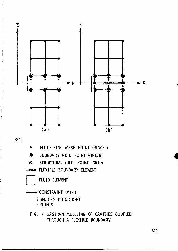
What is required is the definition of a second fluid-structure boundary
for each coupling panel, along with the necessary constraint equation tying
the two boundaries together. Two ways of accomplishing this are shown
schematically in Figure 7. Simple rigid link type MPC equations are sufficient
to tie the boundaries together. At the user's convenience, depending upon the
previous modeling effort, the intervening plates may be defined to attach to
one set of GRIDB points, or alternatively, the plate elements may be defined
relative to a set of GRID points, to which both sets of GRIDB points are
619
connected via MPC equations. The resulting mass and stiffness terms are
identical. Note that the coupled RINGFL and GRID elements defining the boun-
dary are coincident in a given R-Z plane and are located on the panel mid-
plane. If desired_ the coupling panel may be modeled using its vibration
modes, as discussed earlier.
To illustrate the technique, the free vibration modes of two equally
sized enclosures coupled through an intervening flexible panel are calcu-
lated and compared with the results of Reference 6. The finite element
model is shown in Figure 8. For the air in the cavities, the speed of sound
c = 344.4 m/s and the density = 1.225 kg/m 3. For the aluminum plate, the
thickness = 3.2 mm, the density = 2865 kg/m 3, the modulus of elasticity =
493 MPa and Poisson's ratio = 1/3. The plate model had four elements in the
depth direction and was simply supported on all edges.
As a check, the uncoupled cavity and plate natural frequencies have been
calculated and are presented in Table II, along with the results of two
alternate solutions. The first five natural frequencies are within four
percent of the theoretical values. The results for the coupled system are
compared in Table III with the values published in Reference 6. The dif-
ference in frequencies is eight percent or less for the first seven modes.
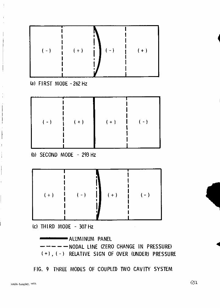
The first three mode shapes are shown in Figure 9 and illustrate the expected
structural-acoustic interaction.
CONCLUDING REMARKS
As in other areas of use, the flexibility and redundanc? inherent in the
NASTRAN code permit the adaptation of the acoustic and hydroelastic modeling
capability to several interesting applications not envisioned in the program
documentation. The discussion and examples included herein are indicative of
the practical structural-acoustic problems which may be analyzed using NASTRAN.
ACKNOWLEDGEMENT
The authors are indebted to Dr. D. L. Smith for providing the experi-
mental data shown in Figure 3.
620
REFERENCES
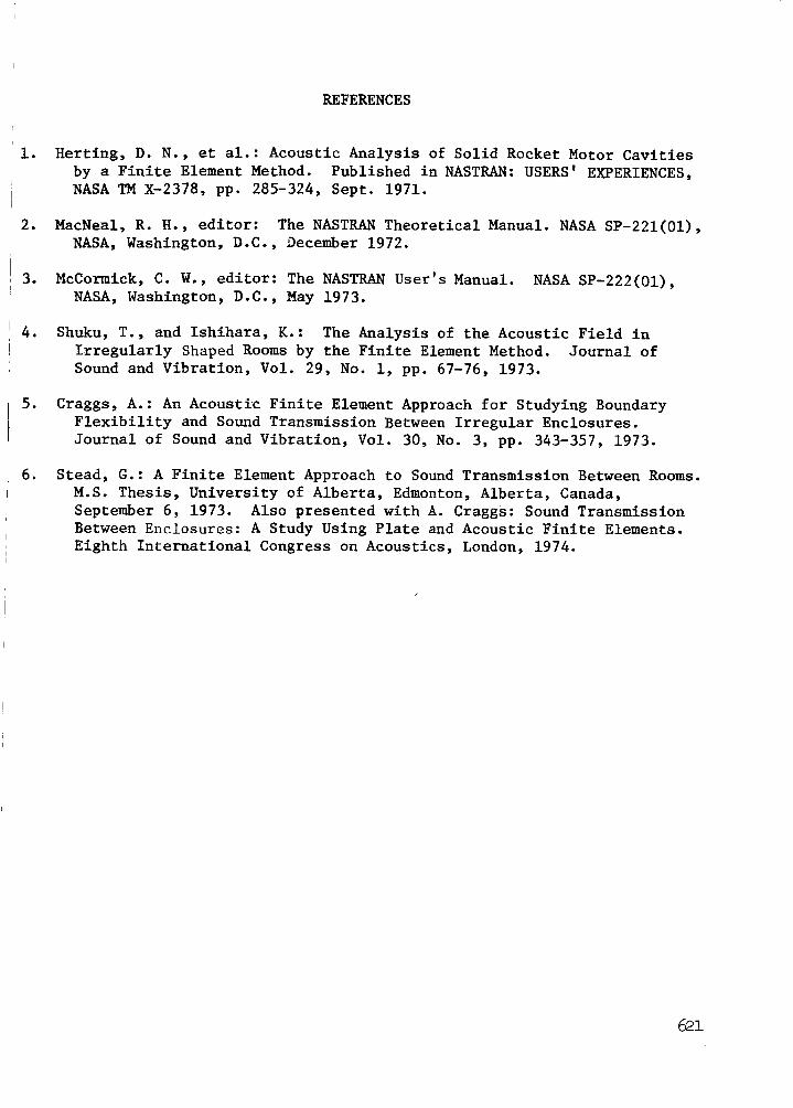
le Herting, D. N., et al.: Acoustic Analysis of Solid Rocket Motor Cavities
by a Finite Element Method. Published in NASTRAN: USERS' EXPERIENCES,
NASA TM X-2378, pp. 285-324, Sept. 1971.
2. MacNeal, R. H., editor: The NASTRAN Theoretical Manual. NASA SP-221(01),
NASA, Washington, D.C., Oecember 1972.
3. McCormick, C. W., editor: The NASTRAN User's Manual. NASA SP-222(01),
NASA, Washington, D.C., May 1973.
e Shuku, T., and Ishihara, K.: The Analysis of the Acoustic Field in
Irregularly Shaped Rooms by the Finite Element Method. Journal of
Sound and Vibration, Vol. 29, No. i, pp. 67-76, 1973.
. Craggs, A.: An Acoustic Finite Element Approach for Studying Boundary
Flexibility and Sound Transmission Between Irregular Enclosures.
Journal of Sound and Vibration, Vol. 30, No. 3, pp. 343-357, 1973.
, Stead, G.: A Finite Element Approach to Sound Transmission Between Rooms.
M.S. Thesis, University of Alberta, Edmonton, Alberta, Canada,
September 6, 1973. Also presented with A. Craggs: Sound Transmission
Between Enclosures: A Study Using Plate and Acoustic Finite Elements.
Eighth International Congress on Acoustics, London, 1974.
621
TABLEI
NATURALFREQUENCIESIN HERTZFORA 2.0 BY i. i m RECTANGULARCAVITY(Calculations Based on c = 340 m/s)