NATIONAL ADVISORY COMMITTEE FOR AERONAUTICS TECHNICAL NOTE 1938 MECHANISMS OF FAILURE OF HIGH NICKEL-ALLOY TURBOJET COMBUSTION LINERS By John W. Weeton Lewis Flight Propulsion Laboratory Cleveland, Ohio Washington October 1949 https://ntrs.nasa.gov/search.jsp?R=19930082613 2018-05-17T11:41:48+00:00Z
Transcript
NATIONAL ADVISORY COMMITTEE
FOR AERONAUTICS
TECHNICAL NOTE 1938
MECHANISMS OF FAILURE OF HIGH NICKEL-ALLOY
TURBOJET COMBUSTION LINERS
By John W. Weeton
Lewis Flight Propulsion Laboratory Cleveland, Ohio
An investigation of turbojet combustion-chamber liners from two types of engine was conducted to determine the factors contri-buting to failure by cracking. Studies were made of "as-fabricated", heat-treated, and mechanically finished liners, on liners after service operation, and on liners after accelerated engine runs.
Buckling was produced at or near most cracks by thermal stresses that resulted from over-all temperature gradients and from temper-ature gradients at individual louvers. Cracks that formed in the buckle were probably caused principally by thermal fatigue of the buckle. Most of the cracks originated at the inner portions of the stress-relieving hole of the louvers in the upper bend of the louver flaps and probably were caused by thermal and mechanical fatigue of the flaps.
Cracking may be retarded and liner life prolonged by removing stress raisers produced by punching operations. Cracks are believed to originate both in the grain boundaries and in fissures produced by punching operations. Surface and subsurface scales of appreciable thicknesses were found at edges of metal exposed to the hot gases. Edges of cracks were lined with either or both types of scale and the subsurface scale (internal oxidation) In particular probably contributed to the cracking mechanism. by forming stress raisers and subsequently lowering resistance to fatigue.
IiIteiIISIIJ(iii
Cobustlon-chRinber liners used in several types of gas-turbine engine have failed both by cracking and buckling. Cracking is par-ticularly serious because small pieces of metal have been known to break off and be carried into turbine blades causing considerable damage; both cracking and buckling disturb the air flow.
2 NACA TN 1938
The liners used In most American engines are made of Inconel, an alloy of the following nominal chemical composition (reference 1, p .4): -
Ni Cr Fe Mn Cu Si C S 78.5 14..0 6.5 0.25 0.2 0.25 0.08 0.015
This alloy is known to have good heat-resistant properties and is one of the best available for applications where f lanes directly contact the metal.
Although the liners used in this investigation are not of the latest design, they are considered typical of liners made with louver flaps or fins protruding into the combustion zone to introduce air for cooling purposes. Determinations of temperature conditions in liners have previously been made at the NACA Lewi's laboratory. Failures were attributed to high local temperature gradients, which were as great as 7000 F per inch. Most cracks occurred in the area of maximum temperature.
The investigation reported herein was conducted to determine the factors that contribute to failures in combustion-chamber liners. Such metallurgical conditions as green-rot (reference 2), sulfide penetration (reference3), oxide penetration, and' carburization were considered. Analysis of such physical conditions as the thermal stresses present in the liner was found to be necessary in completing this research.
The effects of heat treatments and of removing stress raisers from punched edges prior to operation of the liners were determined by running liners in engines and examining cracks that formed.
APPARATUS AND PROCEDURE
Liners. - Liners from two types of turbojet engine were investi-gated. They are designated type A and type B (fig. 1). The type-A liners had cracked in service and had been removed from the engine for this reason. The history of these liners was unavailable, but it was known that an unleaded fuel, probably AN-F-32, was used In their operation. An "as-fabricated" type-A liner was also examined. Type-B liners were run in an engine of the type shown in figure 2 in a cyclic "accelerated-life" run under the following conditions:
NACA TN 1938
3
Duration Rotor speed (rpm)
Gas temperature at exhaust-cone outlet
(OF) (mm) (sec)
4 30 4000 ±50 1100 max.
- 0 15Acceleration to
11,500 1450 ±50 15 0 11,500 ±50 1240 ±20
0 15Deceleration to
4000 1260 max.
The sulfur content of AN-F-32 fuel purchased for the investi-gation varied from 0.011 to 0.044 percent.
Three groups of type-B liners were ,examined. The first group was run for 86 hours and 57 minutes in an engine used in cyclic tests. The liners became so severly cracked that four of them were removed for examination. The other' two groups of liners were modified by heat-treating and mechanical finishing in attempts to reduce failures and were run for 16 hours and. 40 minutes.
Metallurgical examination. - The metallurgical examination pri-mari ly consisted of visual and metaflographic studies of type-A liners that failed in service and type-B liners that had been run in the accelerated-life determinations for 66 hours and 57 minutes.
These liners were visually examined for size, shape, and origin of cracks, for scale patterns that indicate temperature gradients in the metal, for carbonaceous deposits, and for buckling or warping. A large number of cracks were metaliographically studied at high maiifications. Sill sections that contained cracks were removed from the liner, mounted in plastic, and polished with special pre-cautions to preserve edges and scale formations. In genera]., three areas of the inicrospeciinene were examined both etched and unetched.: (1) cracks and adjacent areas, (2) punched edges, and (3) areas away from surfaces exposed to the gaseous atmospheres. The cracks were examined for intercrystafline and tranecrystafline characteristics, scale formations, and possible oxidant penetration of the metal prior to crack formation. The three areas previously mentioned., par-ticularly the punched edges, were checked for evidence of mechanical working, the presence of stress raisers in the form of tears, or fissures, inicrostructural abnormalities, precipitation of carbides in grain boundaries and within grains, carburization, and grain size.
4 NACA TN 1938
Microepeclinens from the as-fabricated type-A liner and from a type-B liner, run for 16 hours and 40 minutes, were also studied. The specimens from the type-A liner were examined to determinethe initial condition of punched edges prior to use, and the specimens from the type-B liner were examined to determine whether the cracks ben In an Intercrystafline or trans crystalline manner.
The samples were examined with a research metaflograph and several auxiliary measuring eyepieces, such as a filar micrometer eyepiece that could measure distances down to a:few hundred thou-sandths of an Inch, and a grain-size measuring eyepiece.
Production of thermal gradients In type-B liner. - An acetylene flame was used to produce hot zones and temperature gradients in a liner similar to those formed in the liners during engine operation. The oxide patterns formed on the liners run for almost 67 hours were used to Indicate the temperature patterns that should be pro-duced with the acetylene flame. In order to determine whether failures similar to those found in liners could be reproduced in short periods of time by artificially creating temperature gradients, the following experiments were made:
1. A thermal gradient was first produced by heating a louver flap and the surrounding metal for 1 minute to a maximum temperature of approximately 17 00° F and cooling the portion immediatel y down-stream of the louver with an air blast. The temperatures were esti-mated from visual observation and the area was examined for buckling and cracking.
2. The zone previously heated was then alternately heated and cooled 30 times and again examined.
3. The upstream portion of the louver in the same zone was then heated to a maximum temperature of approximately 19000 F and the entire downstream portion was air-cooled. This procedure was followed twice, the time of heating in each case being about 2 minutes.
4 • Several louver flaps were then alternately, heated from the inside of the liner to about 1600 0 F and air-cooled. Motion of the flaps during the thermal cycle was observed.
NACA TN 1938 5
Chemical ale. - An attempt was made to scrape corrosion products scale from the liner surfaces in order to determine the presence of sulfur. Samples large enough for chemical analysis could not be obtained., however, because the scale was both thin and tight. Analyses by X-ray and electron diffraction of the scale were attempted but no conclusions could be drawn from the-data. The results seemed to indicate that oxides were present; however, posi-tive identification of individual oxides was impossible with the techniques used. A large number of similar oxides and isomrphs, which may form from the alloying elements in Inconel, made the iden-tification difficult. Carbon deposits, which were as thick as 1/16 inch and. were present in all the liners, were scraped and sent to the National Bureau of Standards for quantitative chemical ana-lyses for carbon and sulfur. In addition, a spectrographiô analysis of the deposits was made.
Heat treatments and mechanical finishing. - In order to determine if heat-treating would improve the resistance of Inconel liners to cracking and if engine runs involving heat-treated liners wee warranted., preliminary investigations were made. Trial specimens were treated. at 9000, 1600°, and 22000 F, air-cooled and water-quenched, examined metallographically, and hardness tested.. The specimens were made of 1/32-inch d.ead. soft Inconel and 5/8-inch holes were punched in them so that in addition to examining the general microstructure ., the punched edges could be checked for d.lstorted grains and the changes that the heat treatments produced. A specimen that was not heat-treated was used as a standard for comparison.
The 9000 F heat treatment was reconmended to give this alloy spring properties and also the best resistance to fatigue and high-temperature exposure (reference 1, p. 6). The 16pO° F heat treatment was expected to soften the alloy by agglomerating precipitates and relieving stresses, whereas the 2200 0 F treatment was expected to be a solution treatment and to increase 'grain size.
Because the microstructural differences found in the trial specimens were significantly great, three type-B liners were selected from stock and were heat.-treated in a neutral atmosphere at 9000 F for 1 hour and air-cooled, at 1600° F for 2 hours and air-quenched, and at 22000 F for 2 hours and air-quenched.
The atmosphere was produced from propane, which had a sulfur content of 0.005 percent. After each sample, except the one treated at 9000 F. had been held at temperature for the required time, it was quickly placed in a cylindrical furnace and air-quenched with a blast of air from all sides.
6 NACA TN 1938
Tree additional type-B liners were heat-treated at these same temperatures. Before being heat-treated, however, the pimohed holes were reamed, sanded, and vapor blasted. An additional liner was also mechanically finished but not heat-treated.
Re1rti ng, sanding, and vapor blasting was employed because mtor-metion from the metalloaphic examinations indicated that service life inl&it be improved by removing the roughness of the edges pro-duced by punching. The procedure was as follows: All air-Intake holes, and all louver holes were reamed by h,ma • The air-intake holes were large enoughto sand by hnmI but the louver holes had to be vapor blasted. Vapor blasting is very similar to sathblastixig, the chief difference being that the abrasive particles are suspended in a liquid rather than in air. The reaming and the wni&fg removed a few thousandths of an inch of metal from the holes. Vapor blasting 'was intended to smooth the edges by a cutting action or by hammering shut the microscopic fissures.
These seven liners were then Installed in an engine with ordinary liners spaced between them. The engine was run for 25. cycles of 'the accelerated—life run (a total of 8 hr and 20 nun), after which all the liners were removed and inspected for cracks. The position and the length of each crack and notations about buckling were recorded.. The engine was reassembled and run for 25 more cycles and the inspec-tion procedure was repeated.
The reaming, sanding, and vapor-blasting treatment seemed to improve the resistance of the liners to cracking and therefore a new set of 14 as-fabrIcated liners was selected to verify the results. Seven of these liners were reamed, sanded, vapor blasted, and installed with ordinary liners In alternate positions. The engine was run for 25 cycles and the liners inspected for cracks. The data previously described for the first trials of this type were again recorded. The engine was then run again for 25 cycles and the liners were reinspeàted..
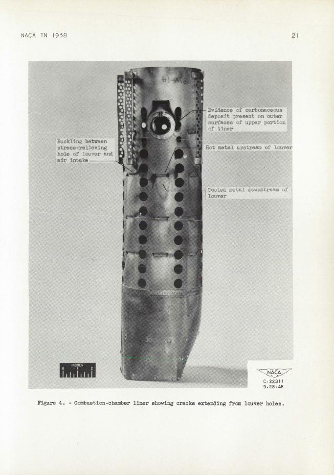
General description of ncrocracka. - Almost all cracks started from the stress-relieving holes of the louvers. The two most co1?nn types of crack are shown in figure 3. (See also fig. 4.)
These cracks originated in the upper bend of the louver flap at the inner edges of the stress-relieving holes (fig. 3(a), point 1). They proceed in a direction approximately perpendicular to the holes for a distance of 1/32 to 1/16 inch. The cracks deviate from their
NACA TN 1938 7
straight paths at this point and turn either away from the center line of the louver or parallel to the center line, as shown in fig-ure 3(a), point 2 • The cracks proceed in a slightly crooked path but continue in the same general direction, away from or parallel to the centerline ., (fig. 3(a), point 3). In extreme cases, cracks extended as far as the air-intake holes. Warping or buckling takes place- at or near almost every crack. In many cases, the warpage forms either a ridge or a groove between the stress-relieving holes of the louvers and the nearest air-intake holes (fig. 3(c)). Buck-ling is most serious in the second row of louvers from the intake end (figs. 1 and 4). The louver flaps (fig. 3(a)) do net warp.
Some of the cracks were jagged and widely separated and looked like tears whereas others were i'1rnite. The smaller cracks were usually imich more crooked than the larger ones. Most of the cracks were located in the second and the third row of louvers from the intake end (figs. 1 and 4).
Surface exandnation and chemical malysia. - - Inner surfaces of , the liners contained carbonaceous deposits, which extended from the intake end downstream for approximately 5 inchea in type-A liners and 8 inches in type-B liners. The thickness of the deposits varied, some large areas having 1/16-inch coatings and a few others having greater thicknesses. A very few localized areas showed green oxide spots in the carbonaceous zone. The National Bureau, of Standards found the carbonaceous material to be approximately 70-percent carbon and 0.3-percent sulfur by microcoinbustion and combustion analyses, respectively. The spectrographic analysis by the National Bureau of Standards did not reveal any significant results. The sulfur picked up by the carbonaceous deposits is not believed to contribute -appreciably to the cracking mechanism because many cracks formed in areas away from the carbonaceous deposits.
Theriiml gradients in liners. - Variation in color of the surface scale permitted estimation of the metal temperature. A dull gray-black coating was found on the hottest portions, particularly the zone between the first and the third row of louvers. The louvers and. the adjacent metal 1 or 2 inches upstream were colored dull gray-black whereas inmed.iately downstream were cool areas relatively unoxidized and only slightly discolored. (fig. 4). Thus, a drastic temperature gradient existed at the individual louvers. Upstream-downstream temperatures at the louvers of type -B liners were measured In another NACA investigation and differences of as imich as 6000 F were found to occur in the second and third rows from the Intake end.
8
NACA TN 1938
The following observations were made on the type-B specimen subjected to thermalgradients:
1 • A thermal gradient produced by heating a louver flap and the surrounding metal to approximately 17000 F for minute caused neither buckling nor cracking.
2.When the area was alternately heated to approximately 1700 0 F and cooled 30 times, a very slight buckle was formed between the louver and the air-intake holes.
3.When a slightly higher temperature of 1900 0 F and a more severe temperature gradient were produced in the area immediately upstream and when heating time was increased to 2 minutes, a greater degree of warping occurred. This warpage was not at all comparable in degree or shape to warpage or buckling produced in liners run in accelerated-life determinations or in service.
4.. When the louver flaps were heated to approximately 16000 F and the metal downstream was kept cool, the louver flaps were bent outward, approximately halving the gap between the edge of the flap and the liner surface. Alternate heating and cooling moved the louver flap inward and outward.
Metallurgical investigation. - The type-A and type-B liners that failed in service and those that were used for long periods of time in the accelerated-life determinations were severely cracked (table V. Cracks of this type are shown in figures 5 and 6. The longer cracks were chiefly transcrystalline (fig. 7) although most of them had inter-crystalline segments. Meny branches from the larger cracks were inter-crystalline.
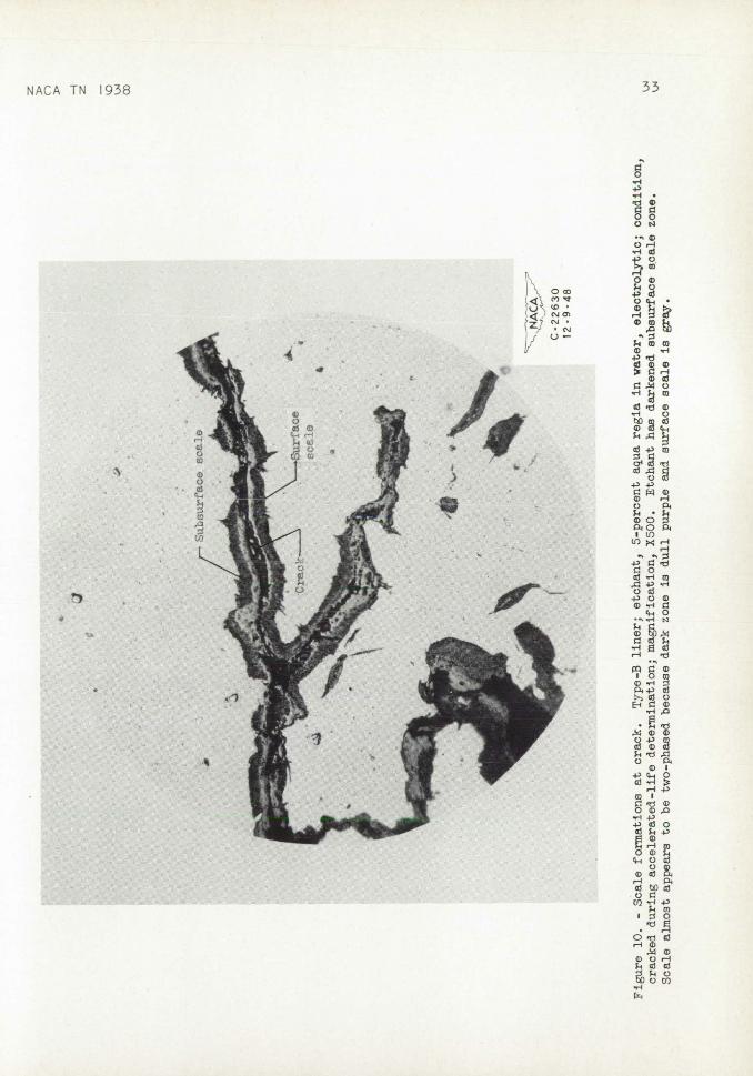
Both surface and subsurface scales were present at most bf the edges of larger cracks (figs. 8 to '10). In a few cases, branôhes from these main cracks appeared to be lined with nothing but surface scale (fig. 11); whereas in many cases branches seemed to be entirely of the subsurface type, (figs. 5 and 9(b)). The separation of layers of scale by metal rather than a crack in some cases leads to the obser-vation that a tubular formation of oxides existed about some of the cracks or branches. Evidence of this type of formation may be seen In figures 5, 8, and 9(b) and a pictorial explanation of what Is believed to occur Is shown in figure 12. Etching sometimes changes the appearance of the scale until it appears to be a two-phase struc-ture (fig. 10). The innermost oxidized zone turns purple and the outer portion remains a dull gray.
NACA TN 1938
9
The punched edges, as well as all other edges exposed to the gaseous atmosphere, are covered with surface scale; very often sub-surface scale is also present.
The punched edges of an as-fabricated type-A liner were bordered by a layer of disturbed and elongated grains and were torn in several places (table I and fig. 13). The fissures produced by tearing were large enough to act as stress raisers or potential sources of cracking, the largest being 0.0019 inch long.
In an ordinary type-B liner run in the accelerated-life run for 16 hours and 40 minutes, some punched edges were found to be lined with snll equlaxed grains, less than A.S.T.N. grain size 8, inasmuch as the cold-worked layer formed by the punching operation had recrystallized. Smell incipient cracks extended from the punched edges through the layer of fine grains (fig. 14). These incipient cracks were so wide that no definite conclusions could be drawn regarding their origin. It is possible that initial cracking, which extended into the metal deeper than the fine-grained layer, preceded from some of the fissures originally present at the punched edges. 3m11 equiaxed grains were not found on the punched edges of the type -B liners run for 66 hours and 57 minutes in the accelerated-life runs, but distorted grains were present in a few samples. Scaling very probably removed almost all traces of original grain structure at the edges.
Quantitative microscopic comparisons of punched and cracked edges. and of inner grains showed no evidence of carburization or decarbüri-zation.
Yellow Intermetallic compounds were found to be scattered uni-formly throughout the microstructure and, for this reason, their presence could not be correlated with the failures. Solid nonmetal-lic inclusions were found in the metal but no abnormal segregations of any type were noticed.
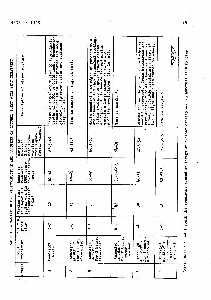
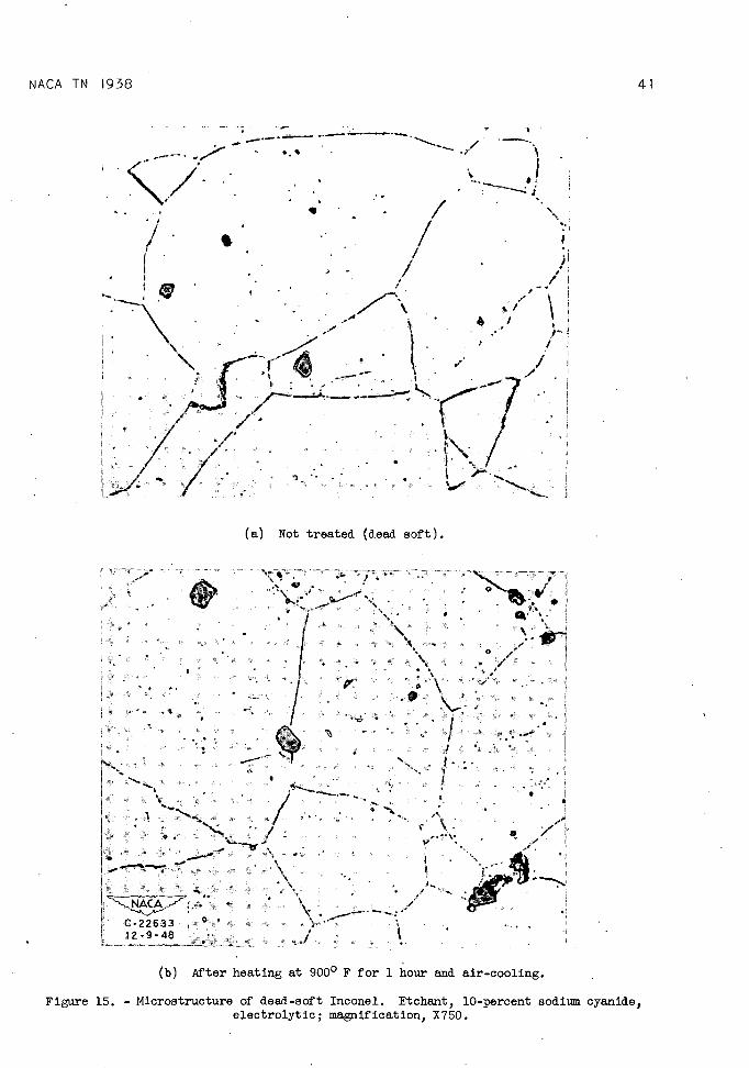
Trial heat treatments. - Heat treatment at 900 0 F produced no significant difference from the as-fabricated sample (figs. 15(a) and 15(b)). Heating at 16000 F caused precipitation of microcon-stituents, whereas heating at 22000 F dissolved most of these micro-constituents (figs. 15(c) and 15(d)). In addition, heating at 22000 F softened the metal, caused grain growth, and aided recrystal-lization. No sigaificant differences were observed between samples that were quenched in air or in water (table II).
10 NACA fl' 1938
Heat treatment and mechanical finishing. - The results of the thermal treatments of type-B liners indicated that the heat treatments selected, were ineffective In preventing cracking. A slight improve-ment was noted in some of the reamed, sanded, and vapor-blasted liners that had been heat-treated. The mechanical finishing of seven as-fabricated type-B liners, however, materially reduced cracking in the accelerated-life determinations as shown in table M.
DISCUSSION OF RESULTS
The location of buckling in the zone in which temperatures and thermal gradients were apparently greatest indicate that thermal stresses of a large magnitude were Induced in the metal. These stresses were a result of the following conditions:
1. Over-all temperature differentials produced In a liner during combustion. The hottest zone is between the first and the third row of louvers from the intake end of the liners.
'2. Temperature gradients produced at individual louvers by secondary combustion air, which enters the louvers and cools the metal InnnedIately downstream. An abrupt line of demarcation between hot and cold areas occurs at or near the stress-relieving holes of the louvers.
Buckling occurs between the stress-relieving holes of the louvers and the air-intake holes because of the geometry of the holes and louvers and the large temperature gradients (fig. 16). Operational conditions such as starting, stopping, and power surging, which pro-duce thermal changes in the liner, are believed to raise and lower the buckle to some extent. The fluctuating thermal stresses thereby produced are believed to fatigue the metal thermally and to produce a crack In the buckle of the type shown in figure 3(c).
By alternately heating and cooling the louver flap, an outward and inward movement of the flap was produced. The operational con-ditions previously described therefore probably caused a similar motion of the flaps producing a thermal fatigue. Any bending of the louver flap would apply maxiim.im bending stresses at the Inner edge of the stress-relieving holes (fig. 3(a), point 1). Because the lower side of a flap projects into the path of the combustion gases and thus becomes hot and the upper side, is cooled by the flow of secondary combustion air, tensile and compressive stresses are pro-duced In upper and lower portions, respectively, as a result of dif-ferences In thermal expansion (fig. 17). These stresses produce the upward bending upon heating.
NACA TN 1938
11
Mechanically produced fatigue stresses are also believed to con-tribute to the cracking mechanism and may result from vibrations of the engine, air flowing over the flaps, and. pulsations that occur dur-ing combustion. Air flow would tend to produce a motion in the flap similar to that of a vibrating reed.
Transcrystalline characteristics of the cracks and the brittle nature of the failure are also indicative of fatigue failures, par-ticuJArly because the longer, more rapidly propagated cracks have few intergranular characteristics except in the branches.
Stress raisers may be classified into two groups: those pro-duced by fabrication processes and those formed after the liner is put into operation.
The investigation has shown the importance of stress raisers produced by the punching operations, namely, that by removing torn and worked metal from punched edges cracking is greatly retarded and liner life thereby increased. Because most cracks originate in the upper bend of the louver flaps at the inner portion of stress-relieving holes, It is possible that the working of the grains in the bend is also harmful. Surface scales, which formed during engine operation are believed not only to lengthen and widen the cracks, but to act as stress raisers at the tips. Subsurface scales, which are also found at most crack edges, are inherently harmful because by expanding the metallic lattice they act as stress raisers and lower resistance to fatigue.
The intercrystalline characteristics of many cracks or branches of cracks and the accompanying scale formations indirectly Indicate that some cracks first start at grain boundaries weakened or stressed by oxide penetrations. Similarly, the improvement in resistance to cracking of mechanically finished liners indicates that other cracks originate from small fissures produced by punching operations. Because the vast majority of cracks were shown to originate in the stress-relieving holes of the louvers, however, and because bending of the flap produces maximum stresses at the stress-relieving holes, it is believed that the cracks are predominantly the result of louver-flap motion. Thermal and mechanical fatigue stresses could therefore cause cracking at the stress-relieving holes even if stress raisers from punching and scaling were not present.
12
NACA TN 1938
SUMMARY OF MSULTS
The investigation of turbojet combustion-chamber liners to determine the factors contributing to failure by cracking yielded the following results:
1. Most cracks originated at the inner portion of the stress-relieving holes of the louvers in the upper bend of the louver flaps. They were propagated at first almost perpendicularly from the edge of the hole but then turned either parallel to or away from the center line of the louver.
2. Buckling was found at or near almost every crack and usually extended from the stress-relieving holes of the louver to the nearest air-intake hole.
3. Some of the cracks probably began in an intercrystalline manner; others are believed to originate in fissures produced. by punching operations. As the cracks enlarged, they tended to become more and more transcrystalline. Most of the cracks were partly intercrystalline or had lntercrystafline branches.
4. Surfaces exposed to hot gases were covered with scale. Sub-surface scale (internal oxidation) occurred at many of these surfaces, particularly the edges of cracks.
5. Neither carburization nor decarburization was detected.
6. No conclusions or correlations in regard to the mechanisms of cracking could be drawn from the grain-size measurements, the pre-sence of intermetallic conxpounxls, or solid nonmetallic inclusions.
7 • Carbonaceous deposits absorbed a relatively large percentage (0.3 percent) of sulfur from combustion gases. The sulfur picked up by these deposits, however, did not contribute appreciably to the failure by cracking.
8. Heat treatments Investigated were ineffectual in preventing cracking.
CONCLUDING PP1
The To1lo'ring observations may be made from this investigation
1. The most common types of crack that extend from the stress-relieving-holes of the louvers probably are caused by thermal and mechanical fatigue of the louver flaps.
NACA TN 1938
13
2. Buckling, which is produced at or near most of the cracks by themE.], stresses, is the result of the production of over-all temperature gradients in the liner and of large temperature gradients formed at individual louvers and air-intake holes by the entrance of secondary combustion air.
3. Cracks that fora in the buckle are believed to, be caused principally by thermal fatigue of the buckle.
• 4. Cracking may be retarded and liner life prolonged by removing stress raisers produced during punching operations by reaming, sanding, and vapor blasting the edges of the punched holes • Some cracks probably originated from 5mRll fissures produced by the punching oper-ation.
5. The surface and subsurface scales, which formed., are believed to lengthen and. widen cracks, act as stress raisers thereby lowering resistance to fatigue, and, in some cases, so weaken or stress grain bound.ares that cracks originate in these boundaries.
Lewis Flight Propulsion Laboratory, National Advisory. Coiimtittee for Aeronautics,
Cleveland, Ohio, October 11, 1948.'
RETcES
1. Anon.: Engineering Properties of Inconel. Bull. T-7, Development and Res. Div., The International Nickel Co., Inc., March 1943.
/De4 2. Evans, Mick P.: Metallic Corrosion Passivity and Protection.
Longeana, Green & Co. (Ne York), 2d. ed., 1946, p. 116.
3. McKay, Robert J., and Worthington, Robert: Corrosion Resistance of Metals and Alloys, chs. XIV and XVII. Reinhold Pub. Corp. ((New York), 1936, pp. 285-326 1' 350-378.
Co 00.-I Co .0(4 00(4 0) .a .4 O (4(4.4.-I (4 .043CO..I-4 as (0 V .0 as • 00.0V(4 OV Co 4) .4 CO043.0 0) .44iO- 4) (10.00.4 E 10 00 (64.E-' (4 4.4..l40.-4 (4 4.00).-4V as OVOCO- CI) 0(4Cl)0OCO to
Co 0)
Cr' I 4..-4 o irs Cr' 4.41-4 0 Co 0. '.0 • '.0 it'. irs 0,-1 0OP I '.0 I 0'. I wV-0 (0 rI IS'. '.0 It'. '0 Cr5 4)4. .4 (6
Figure 5. - Cracks at edge of air-intake hole. Type-A liner; etchant, none; condition, failed in service; magnification, XlOO. Largest crack Is approximately 1/4 inch long.
Figure 6. - Cross section shoving cracks extending into metal from liner surfaces. Type-A liner; etchant, none; condition, failed in service; magnification, XlOO. Cracks shown were located near large crack.
Page intentionally left blank
Page intentionally left blank
NACA TN 1938
25
w
-
a _
AC
C-22627 12-9-46
Figure 7. - Tran.crysta11ine cracking in liner run for 66 hours and 57 minutes. Type-B liner; etchaxit, 5-percent aqua regia In water, electrolytic; magnification, X350.
Page intentionally left blank
.. Page intentionally left blank
NACA TN 1938
27
ta_.a_.. -._._'_
C-22651
(a) Magnification, X60. 12-10-48
FIure 8. — Portion of large crack showing surface and subsurface scale. Type-A liner; etchant, none; condition, failed in service.
Page intentionally left blank
Page intentionally left blank
NACA TN 1938
29
-
r
r
000
'-4
0 0-
4-.
-4.-4 l
-4ci 11-40 00 +
0 '-4 4)
LO
0ca 0
4)
C) W '-4 1 .-i d0
E o
1
'—I c)a5
C)
C)
0 to
H
0
0 '-4 4)
0
'C)
'—I C)
0 C.)
C)
c'J C) z7 c'J.
U- -
il
Page intentionally left blank
Page intentionally left blank
NACA TN 1938
31
(a) Cross-sectional view; magnification, XlOO.
Subsurface scale
(b) Detail A showing surface scale at edge of crack; magnification, X1500.
Figure 9. - Crack extending from punched edge. Type-A liner; etchant, none; condition, failed In service.
Page intentionally left blank
Page intentionally left blank
NACA TN 1938
33
o .p0
ID
o
C)
rI
C)
-4 0
C) 4)4)
C) P
0o p I u)
It)
4) d
5_-1 w
-I-a C) Q)
cs4 0
CC r-1 d
I OW
p4)C)
C) 4)
C) p WI
-p 4_i 0
WI
O W
03 SL4 -P
4 •-1 W ow 4-C)
C)
r-4 P4
(I) 4) -4o)
0d
C) r-1
C) 0tiD
'-4
Page intentionally left blank
Page intentionally left blank
NACA TN 1938
35
F,
C-22631 12-9-48
Figure 11. - Branch of main crack. Type-B liner; etchant, none; condition, cracked during accelerated-life determination; magnification, X1500. Scale appears to be solid, similar to surface scale. Edge of math crack is plated with nickel.
Page intentionally left blank
Page intentionally left blank
(b) Cutaway view of crack.
NACA TN 1938
37
S
Surface and subsurface scales present at edges
v Subsurface scale
\ \ rMetal between crack
\ \
and scale
\ \ \
r- Subsurface crack
() View of crack, which extends from punched hole.
(d) Top view of two-dimensional crack after surface has been olished to section A-A. Compare with photomicrographe (figs. 5, 8, and 9).
(c) Top view of crack and cutaway.
Figure 12. - Pictorial explanation of tubular formation.
Page intentionally left blank
Page intentionally left blank
NACA TN 1938
39
Elongated grains - - - -.
- -
• -
'ø • - .-. *
Sw
-7-quiaxed grains •
Figure 13. - Edge of stress-relieving hole of louver. Type-A liner; etchant, 10-percent sodurn cyanide, electrolytic; condition, as fabricated; magnification X750. Note fissure and elongated grains. Fissure is 0.0019 inch deep.
ch1 '
IV
A
-.•
..•\.
- -. .
.- -•
-.
-.. I• . - .• -- i_ . .
I • •
• 9 S
• -
NACA • - -
/ -.
-/C- 226 32
•
12-9-48
* ,1. • ..-• I • I
Figure 14. - Intercrystalline cracks in liner run for 16 hours and 40 minutes. Type-B liner; etchant, aqua regia and glycerine; condition, cracked during accelerated-life runs: magnification, X250. Incipient intergranular cracks formed at punched edge. Note small grains at edge. Cracks are lined with oxide scale, which does not show.
Page intentionally left blank
Page intentionally left blank
NACA TN 1938 41
,
7
- V
H . ' I
H
(a) Not treated (dead soft).
zrM
/ 4
I0
i1 :z
\ / C22633 . 12.9-48
(b) After heating at 9000 F for 1 hour and air-cooling.