NATIONAL , i '' ! ADVISORY COMMITTEE TECHNICAL NOTE 2661 A SUMMARY OF DIAGONAL TENSION PART I - METHODS OF ANALYSIS By Paul Kuhn, James p. peterson, and L. Ross Levin Langley Aeronautical Laboratory Langley Field, Va. Washington May 1952 ..,,_e.., ELI!U [liX,.iGE Reploducod b',f NATIONAL TECHNICAL INFORMATION SERVICE Sptrngfield, Va. 22151
Transcript
NATIONAL
,
i ''!
ADVISORY COMMITTEE
TECHNICAL NOTE 2661
A SUMMARY OF DIAGONAL TENSION
PART I - METHODS OF ANALYSIS
By Paul Kuhn, James p. peterson,and L. Ross Levin
Langley Aeronautical Laboratory
Langley Field, Va.
Washington
May 1952
..,,_e..,ELI!U [liX,.iGE
Reploducod b',f
NATIONAL TECHNICALINFORMATION SERVICE
Sptrngfield, Va. 22151
A SUMMARY OF DIAGONAL TENSION
PART I - METHOD OF ANALYSIS
PLANE-WEB SYSTEMS
I. Theory of the "Shear-Resistant" Beam
2. Theory of Pure Diagonal Tension
3. Engineering Theory of Incomplete Diagonal Tension
4. Formulas and Graphs for Strength Analysis of Flat-Web Beams
5. Structural Efficiency of Plane-Web Systems
6. Design Procedure
7. Numerical Examples
CURVED-WEB SYSTEMS
8. Theory of Pure Diagonal Tension
9. Engineering Theory of Incomplete Diagonal Tension
lO. Formulas and Graphs for Strength Analysis of Curved-Web Systems
ll. Combined Loading
12. General Applications
13. Numerical Examples
NACA TN 2661
CONTENTS
SUMMARY .............................. 1
INTRODUCTION .......................... 1
FREQUENTLY USED SYMBOLS ..................... 2
PLANE-WEB SYSTEMS ......................... 9
I. Theory of the "Shear-Resistant" Beam ............ 9
2. Theory of Pure Diagonal Tension ............... 6
2.1. Basic concepts ..................... 7
2.2. Theory of primary stresses .............. 7
2.3. Secondary stresses ................... ii
2.4. Behavior of uprights .................. 12
2.9. Shear deformation of diagonal-tenslon web ....... 14
3. Engineering Theory of Incomplete Diagonal Tension ...... 15
3.1. General considerations ............... 16
3.2. Basic stress theory .................. 17
3.3. Remarks on accuracy of basic stress theory ....... 22
3.4. Comparison with analytical theories ......... 23
3.5. Amplification of theory of upright stresses ......
3.6. Calculation of web buckling stress ........... 26
3.7. Failure of the web ................... 27
3.8. Upright failure by column action ....... . ..... 31
3.9. Upright failure by forced crippling .......... 32
3.10. Interaction between column and forced-crippling
failure ....................... 33
3.ii. Web attachments ................... 34
3.12. Remarks on reliability of strength formulas . . . 36
3.13. Yielding ....................... 38
4. Formulas and Graphs for Strength Analysis of Flat-Web Beams . 41
4.1. Effective area of upright ............. 41
4.2. Critical shear stress ................. 42
4.3. Nominal web shear stress ............... 43
4.4. Diagonal-tension factor ............... 43
4.5. Stresses in uprights ................. 43
4.6. Angle of diagonal tension ................ 44
4.7. Maximum web stress .................. 434
4.8. Allowable web stresses ................. 45
4.9. Effective column length of uprights .......... 46
4.10. Allowable stresses for double uprights ......... 46
4.11. Allowable stresses for single uprights ........ 47
4.12. Web-to-flange rivets .................. 48
Precedingpageblank iii
A
;.j
NICA TN 2661
D
4.13. Upright-to-flange rivets ............... 48
4.14. Upright-to-web rivets ............... 49
4.15. Effective shear modulus ................ 50
4.16. Secondary stresses in flanges ............. 50
5. Structural Efficiency of Plane-Web Systems ....... 51
6. Design Procedure ..................... 55
7. Numerical Examples ..................... 56
Example i. Thin-web beam ................. 56
Example 2. Thick-web beam ................ 60
CURVED-WEB SYSTEMS ........................ 63
8. Theory of Pure Diagonal Tension ............... 63
9. Engineering Theory of Incomplete Diagonal Tension ...... 68
9.1. Calculation of web buckling stress .......... 68
9.2. Basic stress theory .................. 68
9.3. Accuracy of basic stress theory ............ 71
9.4. Secondary stresses ................... 71
9.5. Failure of the web .................. 72
9.6. General instability ................ 73
9.7. Strength of stringers ................. 73
9.8. Strength of rings ................. 74
9.9- Web attachments .................... 75
9.10. Repeated buckling .................. 76
i0. Formulas and Graphs for Strength Analysis of Curved-Web
Systems .......................... 78
i0. I. Critical shear stress ............... 78
10.2. Nominal shear stress ................. 78
10.3. Diagonal-tension factor ................ 78
i0.4. Stresses, strains, and angle of diagonal tension .... 79
10.5. Bending moments in stringers ............. 79
10.6. Bending moment in floating ring ............ 80
10.7. Strength of web .................... 80
10.8. Strength check, stringers and rings ........ 80
Previously published methods for stress and strength analysis of
plane and curved shear webs working in diagonal tension are presented
as a unified method. The treatment is sufficiently comprehensive and
detailed to make the paper self-contained. Part I discusses the theory
and methods for calculating the stresses and shear deflections of web
systems as well as the strengths of the web, the stiffeners, and the
riveting. Part II, published separately, presents the experimental
evidence.
INTRODUCTION
J
The development of diagonal-tension webs is one of the most out-
standing examples of departures of aeronautical design from the beaten
paths of structural engineering. Standard structural practice had been
to assume that the load-bearing capacity of a shear web was exhausted
when the web buckled; stiffeners were employed to raise the buckling
stress unless the web was very thick. Wagner demonstrated (reference l)
that a thin web with transverse stiffeners does not "fail" when it
buckles; it merely forms diagonal folds and f_nctions as a series of
tension diagonals, while the stiffeners act es compression posts. The
web-stlffener system thus functions like a tr_ss and is capable of
carrying loads many times greater than those producing buckling of theweb.
For s number of years, it was customary to consider webs either as
"shear-resistant" webs, in which no buckling takes place before failure,
or else as diagonal-tension webs obeying the laws of "pure" diagonal
tension. As a matter of fact, the state of pure diagonal tension is an
ideal one that is only approached asymptotically. Truly shear-resistant
webs are possible but rare in aeronautical practice. Practically, all
webs fall into the intermediate region of "incomplete diagonal tension."
An engineering theory of incomplete diagonal tension is presented herein
which msy be regarded as a method for interpolating between the two
2 NACATN 2661
limiting cases of pure-diagonal-tension and "shear-resistant" webs, thelimiting cases being included. A single unified method of design thusreplaces the two separate methods formerly used. Plane webs as well ascurved webs are considered.
All the formulas and graphs necessary for practical use are collectedin two sections, one dealing with plane webs and one with curved webs.However, competent design work, and especially refinement of designs,requires not only familiarity with the routine application of formulasbut also an understanding of the basis on which the methods rest, theirreliability, and their accuracy. The method of diagonal-tension analysispresented herein is a compoundof simple theory and empiricism. Both con-stituents sre discussed to the extent deemeduseful in aiding the readerto develop an adequate understanding. The detailed presentation of theexperimental evidence, however, is made separately in Part II (refer-ence 2); a study of this evidence is not considered necessary forengineers interested only in application of the methods.
FREQUENTLYUSEDSYMBOLS
A
E
G
Ge
H
I
J
L
Le
M
P
Pu
cross-sectional area, square inches
Young's modulus, ksi
shear modulus, ksi
effective shear modulus (includes effects of diagonal
tension and of plasticity), ksi
force in beam flange due to horizontal component of
diagonal tension, kips
moment of inertia, inches 4
torsion constant, imches 4
length of beam, inches
effective column length of upright, inches
bending moment, inch-klps
force, kips
internal force in upright, kips
i
o
i
NACA TN 2661
Q
R
R vt
RR
S
T
d
dc
e
h
hc
he
hR
hu
k
kss
q
t
3
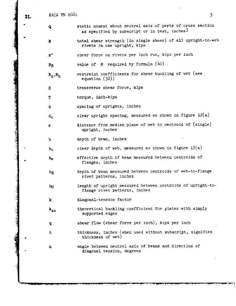
static moment about neutral axis of parts of cross section
as specified by subscript or in text, inches 3
total shear strength (in single shear) of all upright-to-web
rivets in one upright, kips
shear force on rivets per inch run, kips per inch
value of R required by formula (40)
restraint coefficients for shear buckling of web (see
equation (32))
transverse shear force, kips
torque, inch-kips
spacing of uprights, inches
clear upright spacing, measured as shown in figure 12(a)
distance from median plane of web to centroid of (single)
upright, inches
depth of beam, inches
clear depth of web, measured as shown in figure 12(a)
effective depth of beam measured between centroids of
flanges, inches
depth of beam measured between centroids of web-to-flange
rivet patterns, inches
length of upright measured between centroids of upright-to-
flange rivet patterns, inches
diagonal-tension factor
theoretical buckling coefficient for plates with simply
supported edges
shear flow (shear force per inch), kips per inch
thickness, inches (when used without subscript, signifies
thickness of web)
angle between neutral axis of beams and direction of
diagonal tension, degrees
4 NACATN 2661
i_,
8
E
P
(I
(_0
3"
T all
_d
Subscripts:
DY diagonal tens ion
IDT incomplete diagonal tension
PDT pure diagonal tension
F flange
S shear
U upright
W web
all allowable
av average
cr critical
cy compressive yield
e e ffe ct ive
deflection of beam, inches
normal strain
Poisson's ratio
centroidal radius of gyration of cross section of upright
about axis parallel to web, inches (no sheet should be
included)
normal stress, ksi
"basic allowable" stress for forced crippling of uprights
defined by formulas (37)_ ksi
shear stress, ksi
"basic allowable" value of web shear stress given by fig-
ure 19, ksi
flange flexibility factor, defined by expression (19a)
NACATN 2661 5
m_x
ult
maximum
ultimate
R
Z
d
h
Subscripts:
RG
ST
Symbols Used Only for Curved-Web Systems
radius of curvature, inches
curvature parameter, defined in figure 30
spacing of rings, inches
length of arc between stringers, inches
ring
stringer
PLANE-WEB SYSTEMS
i. Theory of the "Shear-Resistant" Beam
Typicsl cross sections of built-up beams are shown in figure I.
When the web is sufficiently thick to resist buckling up to the failing
load (without or with the aid of stiffeners), the beam is called "shear-
buckling resistant" or, for the sake of brevity, "shear resistant." Web
stiffeners, if employed, are usually arranged normal to the longitudinalaxis of the beam and have then no direct influence on the stress
distribution.
If the web-to-flange connections are adequately stiff, the stresses
in built-up beams follow fairly well the formulas of the engineering
theory of bending
Mz (i)I
q = (2)I
F
NACA TN 2661
with the understanding that the shear flow in outstanding legs of flange
angles and similar sections is computed by taking sections such as A-A
in figure l(a). As is well-known, the distribution of the shear flow
over the depth of the web follows a parabolic law. Usually, the dif-
ference between the highest shear flow in the web (along the neutral
axis) and the lowest value (along the rivet line) is rather small, and
the design of the web may be based on the average shear flow
where QF is the static moment about the neutral axis of the flange
area and QW, the static moment of the web material above the neutral
axis. When the depth of the flange is small compared with the depth
of the beam (fig. l(c)) and the bending stresses in the web are neg-
lected, the formulas are simplified to the so-called "plate-girder
formulas"
(3)
M (4)
s (5)q = --
which imply the idealized structure shown on the right in figure l(c).
When the proportions of the cross section are extreme, as in fig-
ures l(a) and l(b), formulas (i) and (2) should be used, because the
use of formulas (3) to (9) may result in large errors. In such cases,
the web-to-flange connection, particularly if riveted, is often over-
loaded and yields at low loads. The beam then no longer acts as an
integr81 unit, the two flanges tend to act as individual beams restrained
by the web, and the calculation of the stresses becomes very difficult
and inaccurate.
2. Theory of Pure Diagonal Tension
The theory of pure diagonal tension was developed by Wagner in
reference 1. The following presentation is confined to those results
that are considered to be of practical usefulness, and the method of
presentation of some items is changed considerably. Mathematical com-
plexities have been omitted, and an empirical formula is introduced for
one important item where Wagner's theory appears to be unconservative.
NACA_ 2661 7
2.1. Basic concepts.- A diagonal-tension beam is defined as a
built-up beam similar in construction to a plate girder but with a web
so thin that it buckles into diagonal folds at a load well below the
design load (fig. 2). A pure-diagonal-tension beam is the theoretical
limiting case in which the buckling of the web takes place at an infini-
tesimally small load. Although practical structures are not likely to
approach this limiting condition closely, the theory of pure diagonal
tension is of importance because it forms the basis of the engineering
theory of diagonal tension presented in section 3.
The action of a diagonal-tension web may be explained with the aid
of the simple structure shown in figure 3(a), consisting of a parallelo-
gram frame of stiff bars, hinged at the corners and braced internally
by two slender diagonals of equal size. As long as the applied load P
is very small, the two diagonals will carry equal and opposite stresses.
At a certain value of P, the compression diagonal will buckle (fig. 3(b))
and thus lose its ability to take additional large increments of stress.
Consequently, if P is increased further by large amounts, the additional
diagonal bracing force must be furnished mostly by the tension diagonal;
at very high applied loads, the stress in the tension diagonal will be
so large that the stress in the compression diagonal is negligible by
comparison.
An analogous change in the state of stress will occur in a similar
frame in which the internal bracing consists of a thin sheet (fig. 3(c)).
At low values of the applied load, the sheet is (practically) in a state
of pure shear, which is statically equivalent to equal tensile and com-
pressive stresses at 45 ° to the frame axes, as indicated on the inset
sketch. At a certain critical value of the load P, the sheet buckles,
and as the load P is increased beyond the critical value, the tensile
stresses become rapidly predominant over the compressive stresses
(fig. 3(d)). The buckles develop a regular pattern of diagonal folds,
inclined at an angle _ and following the lines of the diagonal tensile
stress. When the tensile stress is so large that the compressive stress
can be neglected entirely by comparison, the sheet is said to be in the
state of fully developed or "pure" diagonal tension.
2.2. Theory of primary stresses.- A girder with a web in pure
diagonal tension is shown in figure 4(a). To define this condition
physically, assume that the web is cut into a series of ribbons or strips
of unit width, measured horizontally. Each one of these strips is
inclined at the angle _ to the horizontal axis and is under a uniform
tensile stress q.
The free-body diagram of figure 4(b) shows the internal forces in
the strips intercepted by the section A-A combined into their resultant
Since all strips have the same stress, the resultant is located at mid-
height. The horizontal component HD (= S cot _) of D is balanced
De
8 NACA TN 2661
by compressive forces H in the two flanges.
be equal, D being at mid-height, therefore
The two forces H must
H = - S_ cot _ (6)2
The total flange force is thus
F gcot = (7)h h 2
In the free-body diagram of figure $(c), each strip is cut at right
angles, giving the stress-carrying face a width of sin e; the force on
each strip is therefore _t sin _. The number of strips intercepted by
section A-A is equal to h cot m; the total force D on all strips is
therefore
D = at sin _ x h cot _ = sht cos
But from statics
D
S
sin
Therefore
S
sin-- = uht cos
or
S 2Sa. -- = (8)
ht sin _ cos ht s in 2m
The upright is under compression, counteracting the tendency of the
diagonal tension to pull the flanges together (fig. _(d)). The force PU
acting on each upright consists of the vertical components of the forces
acting in all the strips appertaining to each upright, that is, in d
i
I
:i
4
NACA TN 2661
strips (since the strips have unit width horizontally). But as Just
found, the vertical component of h cot _ strips is equal to S;therefore
9
PU : S : : d : h cot _
or
d tan m (9)
If each strip is connected to the flange by one rivet, the force on this
rivet is equal to the force _t sin e in the strip. Since the strips
are of unit width horizontally, this is the rivet force per inch run,
designated by R". Substitution of the value of q from formula (8)
gives
R" = s (lO)h cos
The angle _ is usually somewhat less than 450; consequently, a slightlyconservative value for most cases is
R" _ 1.414 s (zoa)h
All stresses or forces are now known in terms of the load P, the
dimensions h and d of the beam, and the angle e. To complete the
solution, the angle _ must be found; the principle of least work maybe used to find it.
The internal work in one bay of the beam is given by the expression
W = _ dht + -- AUeh + -- AFd2E 2E
(The subscript e on AU is necessary only for single uprights and will
be explained in connection with formula (22). For double uprights it is
unnecessary.) By substituting into this expression the stress values in
terms of S that follow from formulas (8), (9), and (6), which are
2S 2Ta : : (ii)
ht sin 2_ sin 2_
I0 NACATN 2661
vdtSd tan _ - tan _ (12)aU - hAUe AUe
S ThtaF = - -- cot c_- cot _ (13)
2AF 2AF
differentiating to obtain the minimum, and omitting the constant factorS2/E, there results
dW 8d cos 2_ d2 sin m d cos
d_ ht sin32_ hAUe cos3_ 2AF sin3
Substituting into this expression the values for the stresses given by
equations (Ii), (12), and (13) and equating to zero results in the
relation
4 cos 2m _U _F-_ + - 0
sin22m cos2m sin2m
from which
Ftan2c_ = (14)
a- _U
If o, _F, and SU are expressed in terms of S and _, trigonometric
equations for m are obtained; the most convenient one is
i+ ht
tan4 _ = _FF (15 )
dtI +
AUe
After the angle _ has been computed by formula (19), the stresses can
be computed by formulas (ll) to (13). In plane webs, the angle
generally does not deviate more than a few degrees from an average value
of 40o.
i!
!
3L NACA TN 2661 ii
2.3. Secondar_ stresses.- Formulas (ii), (12), and (13) define the
primary stresses caused directly by the diagonal tension. There are also
secondary stresses which should be taken into account when necessary.
The vertical components of the web stresses s acting on the flanges
cause bending of the flsnges between uprights as shown in figure 9(a).
The flange may be considered as a continuous beam supported by the
uprights; the total bending load in one bay is equal to PU and, if it
is assumed to be uniformly distributed, the primary maximum bending
moment occurs at the upright and is
Sd2tan
Mmax = 12h (16)
In the middle of the bay there is a secondary maximum moment half as
large.
If the bending stiffness of the flanges is small, the deflections
of the flanges indicated in figure 9(a) are sufficient to relieve the
diagonal-tension stress in those diagonal strips that are attached to
the flange near the middle of the bay. The diagonals attached near the
uprights must make up for this deficiency in stress and thus carry higher
stresses than computed on the assumption that all diagonals are equally
loaded. In figure 9(b), this changed distribution of web stress is
indicated schematically by showing tension diagonals beginning only near
the uprights. The redistribution of the web tension stresses also causes
a reduction in the secondary flange bending moments. On the basis of
simplifying assumptions, these effects have been evaluated by Wagner
(reference I) and may be expressed by the following formulas:
2S
_max = (1 + C2)ht sin 2c_ (17)
Sd2tan_ (18)Mmax = c3 lah
Graphs for the factors C 2 and C3 will be given under section h, where
all graphs are collected for convenience of application. The factors are
functions of the flange-flexibility parameter axl, which is defined by
md = d sin _ _(_ +(19)
12 NACATN 2661
where the subscripts T and C denote tension and compression flange,respectively. For practical purposes it is sufficiently accurate to usethe following simplified form of this formula, in which the angle _ isassumedto be slightly less than 45° , and the sumof the reciprocals isreplaced by four times the reciprocal of the sum
a_l _ 0.Td _lh( t+ Ic)(19a)
In reference I, Wagner gave a second value of a_, 1.25 times as large as
the value given by equation (19a), based on a different derivation, and
recommended that the second value be used because it is more conservative.
Previous papers have usually quoted this more conservative value of a_,
but it appears to be more conservative than necessary; it was based on the
assumption that d >> h, a condition which is now avoided in actual
designs.
2.4. Behavior of uprights.- The uprights in a dlagonal-tension beam
may be double (on both sides of the web) or single; both types are alwaysfastened to the web. The buckling strength of the uprights cannot be
computed immediately by ordinary column formules because the web restrains
the uprights against buckling. As soon as an upright begins to buckle out
of the plane of the web, the tension diagonals crossing the upright become
kinked at the upright, and the tensile forces in the diagonals develop
components normal to the web tending to force the upright back into the
plane of the web, as indicated by the auxiliar_ _ sketch in figure 6(a).
The restoring force exerted by the dlagonal-temsion band upon the upright
is evidently proportional to the deflection (Gut of the plane of the web)
of the upright at the point where the diagonal crosses it. The upright
is therefore subjected to a distributed transverse restoring load that is
proportional to the deflection; the problem of finding the buckling loadof such a compression member is well-known, a_d methods of solution may
be found in reference B, for instance. Wagner has given the results of
calculations for double uprights with clamped or pinned ends in the form
of curves (fig. 6(b)), showing the ratio PU/BUE as a function of the
ratio d/h, where PU is the buckling load of the upright and PUE the
Euler load, that is, the buckling load that the same upright would carry
if it were a pin-ended column not fastened to the web.
The assumption of clamped ends would be _ustified only if the ends
of the uprights were fastened rigidly to the flanges and if, in addition,
the flanges had infinite torsional stiffness. Usually, beam flanges
have a rather low torsional stiffness and thus do not Justify the assump-
tion of clamped ends for the uprights. Tests of beams with very thin
webs have furthermore shown that even Wagner's curve for pin-ended double
NACA TN 2661 13
uprights as shown in figure 6(b) is entirely too optimistic for low
values of d/h. The straight line marked "Experiment" in figure 6(b)
(from reference 4) is slightly conservative for the average of the tests
sveilable, but several test points fall so close to it that only a large
number of new tests could justify a higher curve (see Part II (refer-
ence 2)). In order to make this experimental curve applicable to
uprights not in the Euler range, it may be expressed as a formula for
reduced or effective column length of the upright in the form
= h (20)
- 2(d/h)
which is valid for d < 1.5h; for d > 1.5h, of course, Le = h. In
practice, d is seldom chosen larger than h in order to keep the
flange-flexibility factor _d low.
Single uprights are, in effect, eccentrically loaded columns. As
long as the load is infinitesimal, the eccentricity e is evidently the
distance from the plane of the web to the centroid of the upright. If
the uprights are very closely spaced, the web between uprights must
deflect (on the average) in the same manner as the uprights. Under this
condition, the eccentricity is equal to the initial value e all along
the upright and does not change with increase in load. The upright is
therefore designed by the formulas used for an eccentrically loaded com-
pression member with negligible deflection; the bending moment in the
upright is ePu, and the stress in the fibers adjacent to the web is
e2)= AU \ _ AU e
(21)
where p is the radius of gyration of the cross section and AUe is
the effective cross-sectional area, which is evidently defined by the
expression
AU (22)AUe = e2
i +p2
Approximate values of the ratio AUe/A U are shown in figure 7 for typical
i_ single uprights. It should be noted that the web sheet contributes no
i_ "effective width" to the upright area under the condition of pure diagonal
_i___ tens ion cons_idered here. Formula (22)would also apply to a double upright
r_
14NACA TN 2661
not symmetrical about the web. In most cases, however, double uprights
are symmetrical; in this case, e = O, and thus AU e = AU.
If the uprights were extremely wldely spaced, the major portion of
the web would remain in its original plane (on the average, i.e.,
averaging out the buckles). Consequently, the compressive load acting
on the uprights would remain in the original plane, and the upright
would act as an eccentrically loaded column under vertical loads, except
for the modification introduced by the elastic transverse support
furnished by the web. However, barring freak cases, extremely wide
spacing of the uprights would result in the nonuniform distribution of
diagonal tension shown in figure 5(b). In this configuration, the direc-
tion of the compressive load (as seen in a plane transverse to the plane
of the web) is determined essentially by the configuration of the web in
the vicinity of the upright-to-flange Joint; conditions are therefore
again similar to those in the case of the closely spaced uprights. On
the basis of this consideration, formulas (21) and (22) are being used
for all single uprights regardless of spacing, and the available experi-
mental evidence indicates that this practice is acceptable at the present
stage of refinement of the theory.
2.5. Shear deformation of dlagonal-tenslon web.- The shear deforma-
tion of a web working in pure disgonal tension is larger than it would
be if the web were working in true shear (a condition that could be
realized by artificially preventing the buckling). The effective (secant)
shear modulus GpD T of a web in pure diagonal tension can be obtained by
a simple strain-energy calculation as follows: Consider one bay of the
web system and denote by 7 the shear deformation of the bay. The
external work performed during loading is
iSTd=l s SwI = htGpD T
d
The internal strain energy stored is
W 2 = 02 dth + _U--_2AUeh + _F--_2AFd2E 2E E
Now o, OU, and aF can be expressed as functions of S by formulas (ii)
to (13); after transposing terms and canceling, there results the formula
r_q
NACA TN 2661 15
E 4m
GpD_ sin22_
dt ht+ -- tan2_ + -- cot2_
AU e 2AF
which may be transformed with the aid of equation (19) into
(23a)
E (2 dt ht 2_1=2 +--sin +--cosAU e 2AF
(23b)
or
In beams of the type considered here, the flanges are usually so heavy
that the term containing the flange area is negligible. Equation (23a)
can then be simplified to
E 2--=-- (23d)
GpDT sin2_
When the uprights as well as the flanges_are very heavy, the angle
becomes equal to 49 °, and
E
GpD T = _ (23e)
3. Engineering Theory of Incomplete Diagonal Tension
The two preceding sections presented "analytical" theories of the
shear-resistant beam and of the beam in pure diagonal tension. An
engineering or "working" theory will now be developed that connects these
two analytical theories. It may be considered as a method of interpo-
lating between the two analytical theories, guided by an empirical law
of development of the diagonal tension. The purpose of this section is
to present the engineering theory, to explain physical considerations
and certain details, to describe (where it seemed advisable) how empirical
data were obtained, and to indicate the accuracy of the method. The sec-
tion thus forms the basis for section 4, which gives in concise form all
the information needed for actual analysis. This division of subject
16 NACA TN 2661
material between two sections entails some disadvantages for a first
reading; however, the advantage of having section 4 in the form of a
"ready reference" section for practical application, unencumbered by
background material, is felt to outweigh the disadvantage.
3.1. General considerations.- When a gradually increasing load is
applied to a beam with a plane web, stiffened by uprights and free from
large imperfections, the following observations may be made: At low
loads, the beam behaves in accordance with the theory of the shear-
resistant beam; the web remains plane and there are no stresses in the
uprights. At a certain critical load, the web begins to buckle; these
buckles are almost imperceptible, and very careful measurements are
necessary to define the pattern. As the load is increased more and
more, the buckles become deeper and more distinct and the buckle pattern
changes slowly to approach more and more the pattern of parallel foldscharacteristic of well-developed diagonal tension (fig. 2). The process
of buckle formation and development is accompanied by the appearance and
development of axial stresses in the uprights.
It is clear, then, that the theory of the shear-resistant beam can
be verified directly by stress measurements at sufficiently low loads;
It is furthermore possible (although rare) that a beam may remain in the
shear-resistant regime until web fracture or some other failure takes
place. The state of pure diagonal tension, however, is a theoretical
limiting case; a physical beam msy approach this limit fairly closely,
but it can never reach the limit, because some failure will take place
before the limit is reached. A direct experimental verification of the
theory of pure diagonal tension is thus impossible. Fortunately the
theory is so simple (as long as the effect of flexibility of the flanges
may be neglected) that experimental verification is unnecessary.
Physical intuition suggests, and measurements have confirmed, that
the state of pure diagonal tension is approached fairly closely when the
applied load is several hundred times the buckling load. Beam webs thatfail at loads several hundred times the buckling load are encountered in
practice, but they are the exception rather than the rule. For the great
majority of webs, the ratio of failing load to buckling load is much less,
and the theory of pure diagonal tension gives poorer and poorer approxi-
mations as this ratio decreases.
In order to improve the accuracy of the stress prediction, It is
necessary to recognize that mostpractical webs work in incomplete
diagonal tension, or in a state of stress intermediate between true shear
and pure diagonal tension. The first suggestion for such an improvement
was made by Wagner (reference _) for curved webs and was adopted by
others for the design of plane webs. The suggestion as applied to the
braced frame of figures 3(a) and 3(b) may be stated as follows: As the
load P increases from zero, both diagonals work initially. At a certain
I
!q
I
q
LI
!
4
I
NACA TN 2661 17
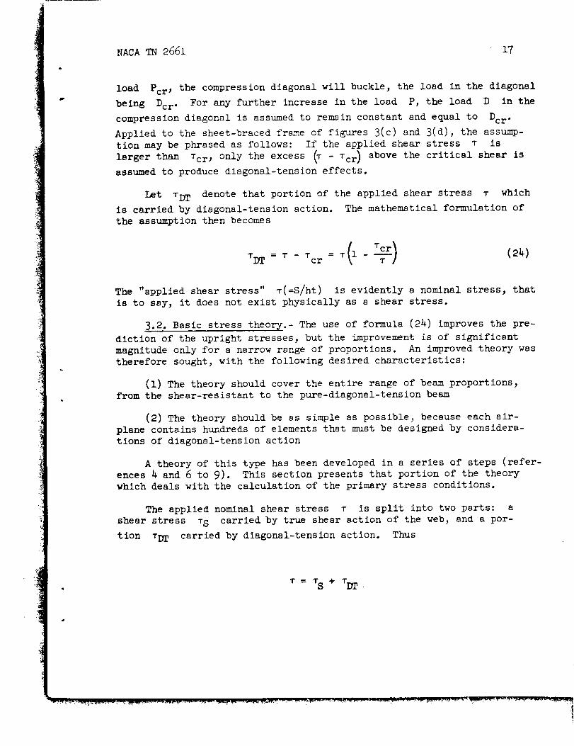
load Pcr, the compression diagonal will buckle, the load in the diagonal
being Dcr. For any further increase in the load P, the load D in the
compression diagonal is assumed to remain constant and equal to Dcr.
Applied to the sheet-braced frame of figures 3(c) and 3(d), the assump-
tion may be phrased as follows: If the applied shear stress T iS
larger than Tcr , only the excess _ - Tcr ) above the critical shear is
assumed to produce diagonal-tension effects.
Let TDT denote that portion of the applied shear stress T which
is carried by diagonal-tension action. The mathematical formulation of
the assumption then becomes
T _ = T 1 T C r = T l ( 2 _ )
The "applied shear stress" T(=S/ht) is evidently a nominal stress, that
is to say, it does not exist physically as a shear stress.
3.2. Basic stress theorv.- The use of formula (24) improves the pre-
diction of the upright stresses, but the improvement is of significant
magnitude only for a narrow range of proportions. An improved theory was
therefore sought, with the following desired characteristics:
(i) The theory should cover the entire range of beam proportions,
from the shear-resistant to the pure-diagonal-tension beam
(2) The theory should be as simple as possible, because each air-
plane contains hundreds of elements that must be designed by considera-
tions of diagonal-tension action
A theory of this type has been developed in a series of steps (refer-
ences _ and 6 to 9). This section presents that portion of the theory
which deals with the calculation of the primary stress conditions.
The applied nominal shear stress T is split into two parts: a
shear stress TS carried by true shear action of the web, and a por-
tion TDT carried by diagonal-tension action. Thus
T= TS + TDT
18
or
NACA TN 2661
T_ = k_ ; _s = (1 - k)_ (29)
where k is called the "diagonal-tension factor." It may be noted that
formula (24) is a special case of this general formulation, with the
factor k defined by
k = 1 Tcr (26)T
by virtue of the assumption made. In the improved theory, the factor k
is still considered to be a function of the "loading ratio" T/Tcr but
was determined empirically from a series of beam tests. The empirical
expression (reference 4) is
k = tsnh .9 lOgl0 (" g _cr) (27)
T
For -- < 2, expression (27) is approximated closely by the expressionTcr
1 (27a)
whe re
T - T crp =
T + Tcr
For T _ Tcr, the factor k is zero and the web is working in true
shear. As the loading ratio T/Tcr approaches infinity, the factor k
approaches unity, which denotes the condition of pure diagonal tension.
Figure 8 shows the state of stress in the web for the limiting
cases (k = 0 and k = 1.0) and for the general intermediate case.
Superposition of the two stress systems in the general case gives for
along the direction and the stress a2 perpendicularthe stress Ol
:I to this direction, respectively,
_I °1 = _ + T(I - k)sin 2_
q
(28a)
4L NACA TN 2661 19
a2 = -T(I - k)sin 2_ (28b)
(For these equations, and for all equations of this section, it is
assumed that the flanges are not sufficiently flexible to produce sig-nificant nonuniformlty of stress.)
The value of k given by expression (27) is less than that given
by (26) except for the limiting cases (----= 1.0 and T-l----+_. ThisVcr Tcr I
fact implies that the true shear stress in the sheet must develop values
larger than Tcr , contrary to the assumption on which expression (24) is
based. At first glance, the assumption that the diagonal compressive
stress does not increase beyond the critical value appears plausible,
particularly if one bears in mind the picture of the braced frame in
figure 3(b). However, it is well-known that deeply corrugated sheet can
carry very high shear stresses before collapsing. In the light of this
fact, it does not seem reasonable to assume that the hardly perceptible
buckles which form in a web loaded Just beyond the critical stress
deprive the sheet immediately of all ability to carry any further increase
in diagonal compressive stress and consequently any increase in trueshear stress.
If the sheet is thus assumed to be able to carry diagonal compressive
stress, it is consistent to assume that it can also carry compressive
stresses parallel to the uprights or to the flanges; in other words, some
effective width of sheet should be assumed to cooperate with the uprights
and the flanges. Trial calculations for the upright stresses developed
in test beams gave satisfactory agreement when the effective width workingwith the upright was assumed to be given by the expression
d e
T: o.5(l - k) (29)
The effective width of 0.5d immediately after buckling may be thought of
as produced by the sinusoidal distribution of stresses indicated in fig-
ure 9. The assumption of linear decrease with k was made as the
simplest expedient possible.
With the assumptions made so far, the formula for the stress in an
upright is obtained by modifying formula (12), which is valid for purediagonal tension, to read
kv tan
aU = - A,,Ue
dT + o.5(l - k)
(3oa)
20 NACA TN 2661
Similarly, formula. (13) for the flange stress produced by the diagonal
tension becomes
kT cot
2A F--+ 0.5(1 - k)ht
(30b)
Formula (14) for the angle m may be written in the modified form
tan_ = _ - EF (30c)
- _U
This form is more general than formula (14), because it is applicable
when web, flanges, and uprights are made of materials having different
Young's moduli. The strains appearing in formula (30c) are defined by
aF _U_F = -_- ; CU = "_" ; :{(1 -.°2)
with the stresses _i and s2 defined by equations (28a) and (28b);
there fore,
= 7_ _ 2k + (i- k)(1 + _)sin 2c_E in'2 (30d)
For practical purposes, sin 2m may be taken as unity, because the
angle m lies between 45 ° and 38 ° for almost all reasonably well designed
webs. Expression (30d) then becomes
¢ _ _ + _ + k(l - _)](3oe)
All charts and graphs for plane diagonal tension shown in this paper were
calculated by use of this approximation. (For curved webs, the approxi-
mation is too inaccurate because the angle = assumes much lower values.)
It might be noted that the buckle pattern immediately after buckling
is not a pattern of parallel folds; this pattern is only approached asym-
totically. Consequently, the term "angle of folds" has, strictly speaking,
no meaning for incomplete diagonal tension, but it is sometimes used for
the sake of brevity instead of the more correct term "angle of diagonal
tension."
|
NACA TN 2661 21
The stress component v(l - k) sin 2_ in formula (28a) arises from
the true shear existing in the web. This component affects the diagonal
web strain c and thus the angle m. The state of diagonal tension
produced by the component kS of the applied shear load is therefore
not s state of "pure" diagonal tension. It is a state of "controlled"
diagonal tension in which the angle _ is affected by the simultaneous
presence of a true shear stress in the web. In order to bring out this
distinction where necessary, the following set of symbols is used:
DT "controlled" diagonal-tension component of the total stress
PDT (for pure diagonal tension) stress system when k = 1.0
The "coupling" between diagonal tension and shear in the IDT case
makes it impossible to calculate the angle _ directly, as in the
PDT csse. Equations (30) must be solved by successive spproximations.
A value of _ is assumed, and equations (30a), (JOb), and (30d) are
evaluated. From the resulting stresses, the strains are computed and
inserted into equation (30c). If the angle computed from (30c) does
not agree with the assumed angle, a new computation cycle is made with
s changed value of _. With s little experience, three cycles are
usually sufficient. For most practical problems, the necessity of going
through this procedure hss been eliminated by the preparation of a chart
(section 4) which gives the snswer directly for beams with flanges
sufficiently heavy to make eF negligible compared with _.
In keeping with the separation of the total stress system in a web
Into a shear part and a dlsgonal-tension pert (expressions (25)), the
shear deformation of a web may be separated into corresponding parts
7ID T = 7S + 7DT
Wlth 7 = ! and T = I, this relation becomesG
i l-k k----- = -- + -- (31a)
22NACA TN 2661
where GDT is evaluated by using formula (23a) in the modified form
appropriate to the DT case
tan2_ cot2_E _ 4 + +
GDT sin22_ AUe+ 0.5(1 k) 2AF_ --+ o.5(i - k)dt ht
(31b)
In most beams, the flange area is sufficiently large to permit neg-
lecting the last term in formula (31b). With this simplification,
the ratio GIDT/G becomes a function of the two parameters AUe/dt and
k (or T/Tcr) and can therefore be given on a simple graph (section 4).
In some rare cases, it may be desirable to estimate the shear defor-
mation up to the failing load of the beam. For some materials, it will
then be necessary to multiply GID T by a plasticity correction factor.
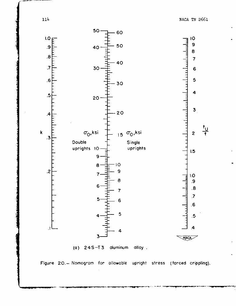
A graph showing this factor for 24S-T3 sheet is given in section 4. The
graph represents an average curve derived from a series of tests on
square panels, stiffened by varying amounts to produce different degrees
of diagonal tension.
3.3- Remarks on accuracy of basic stress theory.- In the strength
design of webs, reasonably accurate results may be achieved with the aid
of empirical data without benefit of a theory of diagonal tension. The
uprights, however, cannot be designed with any degree of reliability
without benefit of such a theory. The appraisal of a theory therefore
should concern itself primarily with the accuracy of predicting the
upright stresses.
The engineering theory given in section 3.2 contains two main elements
strongly affecting the upright stresses that require verification: expres-
sion (27) for the diagonal-tension factor k and expression (29) for the
effective width of sheet. It has not been considered important to date
to attempt separate verification of these two items; special test speci-
mens with construction features not representative of actual beams would
be required, and the elaborate instrumentation necessary would preclude
the possibility of making checks over a wide range of proportions. The
method actually chosen was to measure the upright stresses in a series
of beams. Such measurements constitute only a check on the accuracy with
which expressions (27) and (29), used in conjunction, predict the upright
stresses, but this type of check is considered reasonably satisfactory
except perhaps for thick webs.
The direct evidence used originally to establish the empirical
relation (27) and to chose simultaneously the assumption (29) was obtained
NACATN 2661 23
by analyzing the upright stresses measured on 32 beamstested by theNACA. (See Part II (reference 2).) The criterion used for fixing the
relations was that no unconservative (low) predictions of upright stress
should result for an_ one test beam as long as the load was below about
2/3 of the ultimate. It was possible to fulfill this criterion with-
out being unduly conservative on the average (see Part II for details).
On the average, the predictions were about lO-percent conservative (for
loads below 2/3 of the ultimate). In 20 percent of the cases, the pre-
dictions were about 20-percent conservative. In more than half of the
cases where the prediction was 20-percent or more conservative, the
upright stress was quite low at 2/3 load (about 7 ksi); the estimated
probable accuracy of the upright stress under this condition was about
lO ;_rcent.
At high loads, predicted values of the upright stresses were con-
siderably lower than the observed values for some beams. Analysis of
the data - more particularly those obtained later on thick-web beams -
tended to indicate that the predictions would be low when the shear
stress in the web exceeded the yield value. The explanation is probably
that yielding of the web has a double effect: It causes the effective
width of sheet cooperating with the uprights to decrease more rapidly
and it causes the diagonal tension to develop more rapidly than in the
elastic range. No method of correcting for these effects of yielding
has been developed as yet.
Errors in predicted upright stresses do not entail errors of the
same magnitude in the predicted failing loads of beams. The first reason
for this fact is that the upright stresses increase at a higher rate than
the load. The second - usually more important - reason is that any over-
estimate of the upright stress resulting from an error in k will be
accompanied by an overestimate of the allowable stress, because the
allowsble upright stresses depend on k. For instance, for the two beams
used as numerical examples in section 7, an overestimate of the upright
stress by 10 percent is accompanied by an overestimate of the allowable
stress by 7 percent, and thus by only a 3-percent overestimate of the
failing load of the entire beam. As e result, errors in the predicted
upright stresses appear to be overshadowed by the uncertainties existing
at present in the prediction of the allowable stresses; until these
uncertainties are reduced, corrections for the errors mentioned in the
preceding paragraph may be of small value. It is also pertinent to
observe that the measurements of upright stresses at high loads are notreliable in some cases.
3.4. Comparison with anal_tical theories.- Any analytical theory of
incomplete diagonal tension is unavoidably complex, and attempts to
develop such a theory have been made only fairly recently. Koiter has
developed approximate solutions (reference lO) for a beam in which the
uprights are not connected to the web; they act thus purely as compression
_j
2_ NACA TN 2661
posts and do not influence the buckling of the web. Comparative calcu-
lations made by Koiter for several values of Au/dt give upright
stresses somewhat over 20 percent in excess of those given by the engi-
neering theory when r_/__= 8; for T_!_ = i00, the excess is of the orderTcr Tcr
of 9 percent. The excess stresses may be explained qualitatively by the
fact that the web does not furnish any contribution to the effective area
of the upright if the upright is not connected to the web, as assumed by
Koiter; the discrepancy obviously decreases continuously as the ratio
T/TOt increases. In view of the simplifying assumption of disconnected
uprights made in the theory, the agreement may be considered as satis-
factory. The effective shear modulus calculated by Koiter is somewhat
lower than that calculated by the engineering theory, as would be
expected. For the limiting case of infinitely stiff uprights, the dif-
ferences are 9 and 5 percent for T/Tcr equal to 8 and i00, respectively.
For uprights of practical sizes (Au/dt of 0.67 and 0.18), the differences
are at most 3 percent.
A physically more realistic theory was developed by Denke (refer-
ence ll), who assumed s buckle pattern consistent with the fact that the
uprights are connected to the web. Calculations made by Denke (refer-
ence 12) for a series of 28 NACA test beams show in almost all cases
somewhat lower upright stresses than predicted by the engineering theory.
This implies rather close average agreement with the test results because
the engineering theory is conservative on the average (having been adjusted
to avoid unconservative predictions in any one beam). The predictions by
Denke's theory were slightly unconservative in some cases; significantly
unconservative predictions (about 30 percent) were made for two beams
with very low stiffening ratios Au/dt , a fact that may be of importance
in the application of the theory to thick-web beams.
Koiter's theory was intended to apply primarily at large loading
ratios but was considered by him to be reasonably applicable at loading
ratios down to unity. Denke's theory was set up from the beginning to
cover the entire range of loading ratios from unity to infinity. Such
a t%ide scope of the theories could be obtained only by rather severe
simplifying assumptions. A different line of attack was chosen by
Levy (references 13 and 14), who used 8 more exact theory at the expense
of being restricted to low loading ratios. A comparison of upright loads
calculated by Levy's theory and calculated by the engineering theory is
shown in figure I0. Upright loads rather than stresses are shown to
permit including the limiting case of infinite upright area. The loads
shown are based on the maximum stress, which occurs in the middle of the
upright. The maximum stress will be discussed in the next section; its
use in figure i0 does not affect the comparison and permitted direct use
of Lew's data without conversion. For the case "__qU= 0.25; _ = 0.4'\dth /
NACA TN 2661 25
,7
i
the two theories agree closely. For the other two cases, the engineering
theory gives somewhat unconservative (low) stresses as compared with
Levy's theory. Test results, on the other hand, have indicated so far
that the engineering theory tends to give somewhat conservative values
for the upright stresses, but the number of reliable tests is small for
low values of the ratio T/Tcr (about 2), where the percentage dif-
ferences are largest. It is an open question, therefore, which theoryis closer to the truth.
3.5. Amplification of theory of upright stresses.- Under the con-
dition of pure diagonal tension (and constant shear load along the length
of the beam), the upright stress qU is constant along the length of the
upright. However, it had long been noted in tests that this stress
actually has a maximum value _Umax at the middle of the upright and
decreases towards the ends, a fact referred to as "gusset effect" (refer-
ence 7). The stress aU given by the engineering theory is the average
taken along the length of the upright. (This is the manner in which the
experimental data used to established expression (27) for k were
evaluated.)
Section 3.9 discusses the observation that most upright failures in
practical beams can be ascribed to a local-crippling type of failure. It
seems reasonable to assume that the maximum stress OTJmax is a better
index for such a type of failure than the average value cU. This assump-
tion is supported by the observation that all attempts to base an empirical
formula for the allowable value (causing failure) of the upright stress
showed much larger scatter when aU was used as index than when _Jmax
was used.
The variability of CU, or the ratio _UmaxlqU, is largest Just after
buckling of the web and decreases as the diagonal tension develops. The
accuracy and the scope of the available experimental data are not adequate
to establish the ratio gUmax/_U empirically. On the other hand, the
stress conditions Just beyond buckling are reasonably amenable to a theory
of the type developed by Levy (references 13 and 14). The calculations
in these two references cover two configurations (_ = 0.4 and 1.0).given%--
For lack of better information, the ratio OUmax/a U is assumed to vary
linearly with the ratio d/h; with this assumption, the two calculated
sets of values fix the relation. The calculations cover the range of
T/Tcr up to about 6 or 8 and thus provide only a narrow range of varia-
tion of the factor k; under these conditions, it is not considered
26 NACA TN 2661
Justified to make a more elaborate assumption than that of linear varia-
tion of eUmax/aU with k.
The resulting graph (section 4) thus rests on a limited set of data
and should be considered as tentative. Such experimental evidence as
exists from beam tests tends to indicate that the ratio obtained from
the graph is probably somewhat less reliable than the basic stress
theory itself.
3.6. Calculation of web buckling stress.- Theoretical formulas for
the critical shear stress Tcr are available for plates with all edges
simply supported, all edges clamped, or one pair of edges simply sup-
ported and the other pair clamped. With an accuracy sufficient for all
practical purposes, a formula covering all these cases can be written
in the form
• cr,elastic= kssE/t)2_h + l(Rd - Rh)(d/_(32)
where kss is the theoretical buckling coefficient for a plate with
simply supported edges having a width d and a length h (where
h > d). The coefficients R h and R d are coefficients of edge restraint,
taken as R = I for simply supported edges and R = 1.62 for clamped
edges; the subscripts denote the edge to which the coefficient applies.
Formula (32) represents all available theoretical results (references 3
and I_ to 17) with a msximum error believed to be less than 4 percent; a
more precise evaluation of this error is not possible at present because
some of the published solutions for plates with mixed edge conditions
are known to be somewhat in error because of an erroneous choice of buckle
pattern (reference 18), but the correct values have not yet been computed.
In actual beam webs, the edge supports are furnished by the flanges
and the uprights; the panel edges are thus neither simply supported nor
clamped, and the actual edge conditions may or may not lie between these
two conditions. Some available theories consider the effect of bending
stiffness of the uprights, but they still give results differing over
lO0 percent from test results over a considerable portion of the prac-
tical range of proportions. (The most important reason for the weakness
of the theory is probably the one discussed in section 3.9.) For the
time being, calculations of Tcr for diagonal-tension analysis are
therefore based on formuls (32), supplemented by empirical restraint
coefficients which are functions of the ratio tuft (section 4). It
is probable, however, that theoretical coefficients based on an adequate
5L_ACAT_ 2661 27
theory should eventually replace the empirical coefficients, particularly
for beams designed to fail at low ratios of T/Tcr (say less than 4).
When the uprights are much thinner than the web, the coefficient Rh
becomes very low. In such a case, the critical stress calculated by
formula (32) may be less than that calculated with complete disregard of
the presence of the uprights. The latter value should then be used,because low values of the empirical restraint coefficients (less than
about 0.5) are not covered by tests and thus are unreliable, and because
formula (32) obviously gives meaningless results when Rh approaches
zero.
Formula (32) is valid only as long as the calculated critical stress
is below the limit of proportionality for the material used. Beyond this
limit, corrections based on the theory of plastic buckling must be applied;
the theories presented in references 19 and 20 have been used to compute
the correction curves given in section 4 for bare end clad webs,
respectively.
3.7. Failure of the web.- As is well-known, the engineering beam
theory is not entirely capable of predicting the failure of beams, even
of simple cross sections; it must be supplemented by empirically deter-
mined moduli of rupture. In an analogous manner, the engineering theory
of incomplete diagonal tension must be supplemented by empirical failure
moduli. This section deals with the failure of webs. Since a modulus
of rupture is a fictitious stress, the method of computing the stress
must also be specified and constitutes an integral part of the definition
of the modulus.
The stress in a web may be expressed either as a nominal shear stress
or as a nominal diagonal-tension stress; the first alternative is used
here. The peak nominal stress in a sheet panel may then be defined by the
formula
(33a)
In this expression, C1 is a correction factor to allow for the fact
that the angle _ of the diagonal tension differs from 45°; by for-
mule (ii), for k = 1
i
Cl = sin 2_ i
28 NACATN 2661
The factor C 2 is the stress-concentration factor arising from flexi-
bility of the flanges and introduced in equation (17). (Both factors
are given graphically in section 4.) The effect of factor C2 is
assumed to vary linearly with k in expression (33a) for lack of better
data. The effect of factor C 1 is assumed to vary with the square of k
on the basis of test results on curved diagonal-tension webs, in which
the angle m varies over a wider range than in plane webs. In the plane
webs under consideration here, the angle is usually near 40° , and the
factor C 1 is unimportant.
In curved webs, the determination of the angle _ (and thus the
determination of C1) is somewhat tedious. Consequently, a slightly
different procedure for calculating the web strength is used that may
also be applied to plane webs, with results differing at most by 2 to
3 percent from those obtained by the first procedure. (This error isless than the scatter found in tests of nominally identical webs.) In
the second procedure, the peak web stress is written as nominal shear
stress in the form
-rmax = T (1 + kC2)(33b)
that is to say, the angle factor C1 is omitted. On the other hand,
the allowable stress is now no longer considered as a property of the
material alone but is considered to be a function of the angle _PDT'
the angle that the folds would assume if the web were in a state of pure
diagonal tension.
In order to determine the allowable stresses, a series of 97 tests
was made on long webs of 24S-T3 and Alclad 79S-T6 aluminum alloy (refer-
ence 21). The external loads were applied as equal and opposite axial
forces to the flanges; the loading was thus essentially a pure shear
loading. The diagonal-tension factor k st failure was varied chiefly
by using different h/t ratios of the webs. The rivet factor
1 Diameter_ was varied from about 0.6 to about 0.9; 0.6 is about the- Pitch /
lowest value likely to be encountered in practice, 0.9 marks roughly the
region where rivet failure or sheet bearing failure becomes critical.
The uprights were heavy but were not connected to the web except for the
lowest values of k and were not connected to the flanges in order to
eliminate "Vierendeel frame" action. In most tests, bolts were used
instead of rivets, with the nuts drawn up "Just snug" because friction
between the sheet and the flange is a very important, but highly variable_
factor. The sheet was protected from direct contact with the bolt heads
by heavy washers. Some tests were made with the nuts tight, and older
"i
NACA TN 2661 29
tests with riveted panels were used to estimate the increase in strength
obtained by friction effects.
Almost all tests fell within a scatter band of ±i0 percent from the
average for a given value of k. The scatter may be attributed to dif-
ferences in friction, material properties_ and workmanship, the first
factor probably being the largest one. About 85 percent of the tests
fell within ±5 percent of the average and, st low values of k, more
than 90 percent fell within the ±5-percent band. The curves of "basic
allowable" stress given in section 4 (denoted by T*al I and shown in
fig. 19) represent the line l0 percent below the average of the scatter
band; they are furthermore corrected as noted to specified material
properties (defined by the ultimate tensile strengths) which lie well
below the typical values.
Because of the large sizes of the flanges and uprights used in the
tests, the angle factor C1 was zero (m = mPDT = 45o) and the stress-
concentration factor C2 was also zero. The tests thus established the
basic allowable values of T'max, or of Tma x for _PDT = 45 ° (shown
as the top curves in figs. 19(a) and 19(b) of section 4). Detailed test
results are given in Pert II.
The curves for values of mPDT other than 45 ° were calculated as
follows: By formula (ll), the tensile stresses vary inversely with
sin 2mPDT; the values of T*al I for k = 1.O were therefore calculated
by multiplying the experimental value obtained for 45 ° by sin 2m. In
webs working in true shear, the allowable stress is evidently not
influenced by the sizes of the flanges and the uprights; therefore, all
curves of T*al I must have ss common end point at k = 0 the experi-
mental value of allowable true shear stress. For any given value of
C?DT, the two end points of the curve were thus established. The con-
necting curve was drawn on the assumption that the difference between
the curve in question and the experimental curve for 4_ ° varied linearly
with the factor k.
The curves for angles well below 45 ° are needed mostly for curved
webs rather than plane webs, and such experimental confirmation as
exists for low angles was obtained on curved webs.
The name "basic" was given to those curves because they serve as s
basis for a system of computation. They determine directly the allowabl _
stresses for the attachment conditions that existed in the main tests
(bolts with heads protected by washers, nuts Just snug). For other con-
ditions (rivets, web sandwiched between flange angles, etc.), the basic
allowable values are modified as specified in section 4 on the basis of
auxiliary tests.
R•
3oNACA TN 2661
It should be noted that all shear stresses are based on the gross
section, not on the net section between rivet holes. This simple pro-
cedure is possible because the tests disclosed an interesting fact:
When the ratio of rivet pitch to diameter was varied (for a fixed value
of the diagonal-tension factor k), it was found that not the failing
stress on the net section, but the failing stress on the gross section
was a constant w--_thin the scatter limits mentioned previously. This some-
what surprising result indicates that the stress-concentration factor
varies with the rivet factor in such a manner as to Just offset the
change in net section. Qualitatively, the change in stress-concentration
factor agrees with that found in straight tension tests: As the net sec-
tion decreases (for constant gross section), the stress distribution
becomes more uniform, and the ultimate stress based on the net section
approaches the ultimate found in standard tensile specimens without holes.
The quantitative result that the change in stress concentration Justoffsets the change in net area should, of course, be rmgarded as a pecu-
liarity of the specific materials tested.
In the relatively thin sheets used in these tests, the diagonal-
tension folds are quite deep, and sharp local buckles form in the vicinity
of the bolt heads. If the bolt heads bear directly on the sheet, these
local buckles csuse additional stresses around the bolts that lower the
allowable shear stress. In a number of comparative tests (reference 22
and other data), the decrease was found to be about lO percent. Rivet
heads are larger than the corresponding bolt heads and thus presumably
give about the same conditions as bolt heads protected by washers. The
difference cannot be shown directly by tests because rivets have the
additional feature of setting up friction, which can be fairly well
eliminated when bolts are used by leaving the nuts loose. Use of the
"basic allowable" curves when the attachment is by means of rivets
would therefore imply the assumption that the rivets have lost their
clamping pressure in service but that there are no additional localstresses under the rivet heads even if no washers are used. Tests on
riveted panels and beams (using no washers) showed generally strengths
at least l0 percent higher than those developed with Just-snug bolts
with washers.
Because the buckles in thicker sheet are less severe, one might
believe that the thicker sheet would have higher failing stresses; how-
ever, a few beam tests on sheet up to 0.2 inch thick do not support this
belief. All these tests, however, did fall in the center of the scatter
band or higher, so that somewhat higher allowables might be permissible
in thicker sheets.
When single uprights are used, the simplest construction results if
the web is riveted to the outside of the flange angle, because the
uprights then require no Joggling. Preliminary results indicate that
such sn unsymmetrical arrangement of the web results in lower web failing
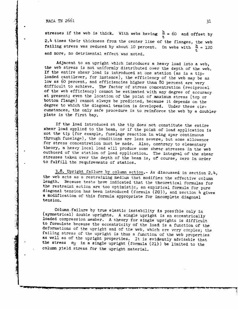
NACATN 2661 31
stresses if the web is thick. With webs having _ = 60 and offset byt
2.4 times their thickness from the center line of the flanges, the web
failing stress was reduced by about lO percent. On webs with _ = 120t
and more, no detrimental effect was noted.
Adjacent to an upright which introduces a heavy load into a web,
the web stress is not uniformly distributed over the depth of the web.
If the entire shear load is introduced at one station (as in a tip-
loaded cantilever, for instance), the efficiency of the web may be as
low as 60 percent, and efficiencies higher than 80 percent are very
difficult to achieve. The factor of stress concentration (reciprocal
of the web efficiency) cannot be estimated with any degree of accuracy
at present; even the location of the point of maximum stress (top or
bottom flange) cannot always be predicted, because it depends on the
degree to which the diagonal tension is developed. Under these cir-
cumstances, the only safe procedure is to reinforce the web by a doublerplate in the first bay.
If the load introduced at the tip does not constitute the entire
shear load applied to the beam, or if the point of load application is
not the tip (for example, fuselage reaction in wing spar continuous
through fuselage), the conditions are less severe, but some allowance
for stress concentration must be made. Also, contrary to elementary
theory, a heavy local load will produce some shear stresses in the web
outboard of the station of load application. The integral of the shear
stresses taken over the depth of the beam is, Qf course, zero in order
to fulfill the requirements of statics.
3.8. Upright failure by column action.- As discussed in section 2.4,
the web acts as s restraining medium that modifies the effective column
length. Because tests have indicated that the theoretical formulas for
the restraint action are too optimistic, an empirical formula for pure
diagonal tension has been introduced (formula (20)), and section 4 gives
s modification of this formula appropriste for imcomplete diagonaltension.
Column failure by true elastic instability is possible only in
(symmetrical) double uprights. A single upright is an eccentrically
loaded compression member. A theory for single ncprights is difficult
to formulate because the eccentricity of the los_ is a function of the
deformations of the upright and of the web, which are very complex; the
failing stress of the upright is thus a function of the web properties
as well as of the upright properties. It is evidently advisable that
the stress _U in a single upright (formula (21_) be limited to the
column yield stress for the upright material.
i
32NACA TN 2661
In four tests of beams with very slender single uprights, a two-
half-wave type of failure has been observed. The wave form was clearly
visible at low loads and, at two-thirds of the ultimate load, the
deformstlons were indisputably excessive on three beams. As a tentative
method of avoiding this situation, it is suggested that the average
stress over the cross section of the upright be limited to the allowable
column stress for a slenderness ratio huI20. This rule is conservative
(in general) as far as ultimate strength is concerned, but the sacrifice
appears to be necessary in order to achieve ressonably small deformations
at limit load.
3.9. Upright failure by forced crippling.- Almost all failures on
uprights (double or single) of open section may be explained as being
caused by forced crippling. The deformation picture may be described
as follows: Let the angle section shown in figure ll represent a por-
tion of the upright. The shear buckle forming in the web forces the
free edge A-A of the attached leg to take on a wave form. The amplitude
of this wave is a maximum at the free edge and zero along the heel B-B
of the angle. If the deformations are large, then a similar wave appears
along the free edge C-C of the outstanding leg, but the amplitude is very
much smaller, because this edge is under tension, the upright being under
eccentric bending. If the stiffener were of Z-section, the line C-C
would also remain straight, and only an extremely small wave amplitude
would be noticed along the free edge of the free leg.
(The deformation picture Just described probably indicates the main
reason why the existing theories of the buckling of stiffened webs often
give very poor results. They assume that the stiffener bends with thesheet without deformation of the cross section. This assumption might
yield an acceptable result if the stiffener were welded to the web along
the heel llne B-B. Actually, it is riveted to the web along a line
between the free edge A-A and the heel llne B-B. Thus, the bending
stiffness that comes into play is more nearly that of the attached leg
alone, rather than that of the entire stiffener.)
The physical action of a strip along the edge A-A of the upright is
analogous to that of a beam-column. The strip is under the compressive
stress oU created by the diagonal tension, and under a lateral pressure
exerted by the web buckle. The problem is thus not one of elastic insta-
bility, as is true of the problems normally called local crippling.
Large deformations can and do occur while the compressive stress in the
upright is negligible.
No theoretical attention has been given to the problem of forced
crippling, although the possibility that forced crippling acts as a
"trigger mechanism" for failure had been suggested by several experi-
menters. It must be admitted that a theoretical analysis would be very
!
NACA TN 2661 33
difficult because _ large-deflection theory of plates would be required
(at least if the _aalysls is carried to the ultimate load, as it should
in order to be practically useful). An empirical formula has therefore
been developed that fits single or double uprights with a change in coef-
ficient (section 2). A rather large collection of data was available to
establish this fo._nula because almost all upright failures encountered
could be ascribed to forced crippling. The cross sections included
angles and Z-sections, both with and without llps, and J-sections.
The probability of failure by forced crippling evidently depends on
the "relative sturdiness" of upright and web; a sturdy upright will not
be deformed severely by a thin web. The empirical formula developed
assumes that the relative sturdiness can be measured by the ratio of
thickness of upright to thickness of web. Such a single-parameter
description of the complex phenomenon of forced local crippling can
obviously be no more than a first approximation and therefore cannot
give very high accuracy. The test results show a scatter band of
_20 percent. The constants recommended for design are based on the lower
edge of the scatter band.
No information is available on forced crippling of closed-sectlon
uprights; it is doubtful whether closed uprights with flat sides offer
material advantages over open sections.
Upright sections are not infrequently chosen by the criterion that
the moment of inertia should be a maximum for a given area. This one-
sided emphasis is quite misleading; a greater moment of inertia for a
given area means a thinner section, which has less local bending stiff-
ness and is thus more susceptible to forced crippling. In order to
demonstrate this fact, two beams (about 70 in. deep) were built, having
the same web thickness, upright spacing, and upright area, but differing
in moment of inertia of the (single) uprights. The moment of inertia
was doubled on the second beam, but this beam carried only 79 percent
of the load carried by the first beam; the first beam failed by web
rupture, the second, by forced crippling of the uprights. (See Part II.)
3.i0. Interaction between column and forced-crippling failure.- It
should be realized that column failure and forced-crippllng failure are
not, in reality, two completely independent types of failure; forceddeformation of the cross sections will affect the column behavior of the
upright. A certain amount of interaction effect is included automaticallyin the formulas for the allowable stresses because they are empirical.
It is possible, however, that for very different proportions, or for
different loading conditions than those that existed in the tests, some
direct allowance for interaction may be necessary. For instance, the
uprights were, in all but a very few tests, subjected only to the com-
pressive loads arising out of the dlagonal-tension action of the webs;
they were not subjected to externally applied compressive loads. In
NACATN 2661B4
cases where the compressive stress due to externally applied loads is of
the same order of magnitude as that caused by the diagonal-tension
action, the problem of interaction between forced crippling and column
buckling may become serious. It might be mentioned that a forced-
crippling problem also exists when externally applied compression is the
only force acting, that is to say, the skin buckles of a stiffened com-
pression panel generally reduce the failing stress of the attached
stiffener below that of the free stiffener.
3.11. Web attachments.- The web-to-flange rivets or bolts carry a
load per inch run R" equal to S/h for a shear-reslstant beam (k = O)
and 1.414S/h for a beam in pure diagonal tension (k = l, see formula (10a)).
Linear interpolation between these two values gives for incomplete diagonal
tension
s (i + 0.41 k)R" =
(34)
The depth hR used in formula (34) is the distance between the rivet
lines in the top and bottom flanges if the rivet lines are single, or
the distance between the centrolds of rivet patterns in the most general
case of multiple rivet lines. There is s wide-spread custom of using
the effective depth he instead of hR, a practice that has been found
to give definitely unconservative results on some test beams; in many
cases, of course, the unconservatism is sufficiently small to be covered
by the hidden factors of safety usually existing in rivet design.
Literal interpretation of the basic concept of incomplete diagonal
tension would require that the rivet load be considered as made up of
two components: a force (i - k)S/h acting horizontally, caused by
the shear component of the load, and a force kS/h cos _ (according to
formula (I0)) acting at the angle _. The two forces should be added
vectorially. The resulting formula for R" is more complicated than
formula (34) and gives somewhat lower values (except, of course, at
k = 0 and k = I). This formula might be considered more rational than
formula (34), but this purported greater rationality is spurious because
the factor k expresses average stress conditions in the panel, and the
conditions along the riveted edge are not average. Experimentally, the
"more rational" formula has been found to be somewhat unconservative
(see Part II) and is therefore not given here.
The upright-to-flange rivets simply carry the upright load into the
flange and require no special comments.
The upright-to-web rivets must be investigated for several conditions
that Justify some comments.
6L NACA TN 2661 35
i
In double uprights, the rivets must have sufficient shear strength
to permit the upright to develop its potential column strength. In
civil-engineering practice, where built-up columns are frequent, various
rules are used to determine the required shear strength, and they lead
to widely different results. Tests were therefore made on several series
of double-angle columns (reference 23); the fo_-nula derived from these
tests (given in section 4.14) is essentially based on one of the methods
used in civil engineering, in which the shear strength is computed as
though the member were loaded not as a column, but as a beam (by a
distributed transverse load).
A riveted-up section evidently cannot achieve the same strength as
an (otherwise identical) monolithic section. For the purpose of obtaining
the formula just mentioned, the required shear strength has been defined
arbitrarily as the shear strength that will permit the riveted-up section
to develop 98 percent of the strength of the monolithic section. To be
entirely consistent, then, the usual column allowable stress should be
reduced by 2 percent; however, this small reduction may be omitted because
the formula for effective column length is somewhat conservative. If the
rivet strength provided in an actual case is much less than that given
by the formula, the allowable column stress must be reduced. This situa-
tion should not arise in new designs, but it did arise in a number of
the test beams designed before the formula was developed. A reduction
factor derived from the tests is given in section 4.
With single uprights, the shear buckles in the web tend to lift the
sheet off the upright; with double uprights, the web buckles tend to
split the two upright sections apart. These actions produce tensile
forces in the rivets, and sn empirical criterion for tensile strength
is therefore given in section 4. It should be noted that tensile failure
of a rivet is equivalent to tensile failure of the rivet shank only when
the head is relatively high. With low rivet heads, the tensile failure
is caused by shearing the head off axially; with flush rivets, tensile
failure may be caused by the rivet pulling through the sheet. Because
flush rivets have a low tensile strength, the problem usually demands
most attention on the outside skin; it is therefore discussed somewhat
more fully in the section 9.9, which deals with the attachment of curved
webs.
The criterion for the required tensile strength of rivets is based
on rather scanty direct evidence (Part II). However, out of 135 beams
tested by manufacturers, the great majority satisfied the criterion
(which is one reason why the 8vailable direct evidence is scanty). One
large company is using a shear criterion which gives practically thesame results as the tensile criterion does for rivets where shank failure
determines the tensile strength. It is believed, therefore, that the
criterion is not unduly severe, although it may be conservative.
.... T ......
36 NACA TN 2661
3.12. Remarks on reliabilit 7 of strength formulas.- In sections 3.7
to 3.11, the various types of failures have been discussed in a general
fashion. In section h, specific formulas recommended for use in design
are presented. The formulas are derived fro_ test plots forming scatter
bands and are consistently based on the lower edges of the scatter bands;
they are thus intended to give a very high degree of assurance that any
given beam under consideration will carry the design load. Because the
scatter bands are fairly wide, this high degree of assurance of safety
is necessarily obtained at the expense of considerable conservatism for
most beams.
The following remarks are based on the analysis of 64 beams tested
by the NACA, 135 beams tested by five manufact_arers, and about 140 NACA
tests made to establish the strength of webs under nearly pure shear
loading. The remarks are rather general; a m_re detailed discussion is
given in Part II.
The degree to which the formulas fulfill the intended purpose of
safe design may be characterized by the following statement: It is
estimated that predictions unconservative by _ore than 2 percent should
occur in less than 9 percent of all cases, and predictions unconserva-
tive by more than 5 percent should occur only with negligible frequency.
Excluded are local regions where large loads are introduced and beams
with very flexible flanges (axi > 2.5).
The scatter exhibited in web-rupture test_ may be ascribed to thevariations of three factors:
(i) Material properties
(2) Local stress conditions around rivet_ or bolts
(3) Friction between sheet and flange
In the NACA tests on webs under pure shear lomding, the material prop-
erties were fairly uniform, and individual corrections were made. The
webs were attached by bolts, with the nuts car_-fully adjusted to be
Just snug; the friction between the sheet and the flange was therefore
small. Nevertheless, the width of the scatter band was about ±lO percent,
which must be attributed mostly to variations _n item (2). In beam tests,
then, the failing strengths of webs may be expected to average l0 percent
higher than the recommended 811owable values adjusted to actual material
properties, and occasional values 20 percent higher than the allowables
may be found. An additional increase above the allowable may be realized
from the portal-frame effect (see _pendix .
It may be remarked that the procedure of correcting for actual
material properties is not very accurate. This correction is commonly
!
NACA TN 2661 37
based on the tensile strength developed by a coupon of standard shape.
Such a single tensile coupon neither evaluates possible anisotropy, nor
does it evaluate compressive properties; these factors should be evaluated
because shear is equivalent to tension and compression at ±45 ° to the axis.
Furthermore, the standard tensile test does not evaluate the static notch
sensitivity of the material. Fragmentary test evidence indicates that
an increase in tensile strength brought about by a deviation from the
specified heat treatment may be more than overbalanced by an increase of
the static notch sensitivity. The standard tensile test therefore does
not appear to be a very reliable index for correcting the strength of a
web that fails at rivet holes, although its use is probably preferable tomaking no correction.
Plots of upright stresses causing failure by forced crippling show
a width of scatter band of ±20 percent. Thus, the average of a suffi-
ciently large number of tests of different designs may be expected to
be 1 = 1.25 times higher than the recommended allowable values, and0.8
occasional uprights may develop 1.5 times the allowable value. For
uprights failing by column action, the data available are insufficient
to establish a width of scatter band. Taken at face value, however,
they appear to indicate about the same width of band as for failure by
forced crippling. The width of the scatter bands for upright failure
is probably caused largely by inadequacy of the empirical formulas, and
only to a very minor extent by variation of material properties. Con-
sequently, higher allowable stresses would seem acceptable if they areverified for any given case by a specific test.
It should be remarked that upright failure st a load 1.5 times the
design load is, of course, possible only if the web also develops
1.5 times the design load. In a well-designed beam, such a contingency
should not arise because the scatter band for web strength is much
narrower. Many of the test beams under discussion here, however, weredeliberately built with overstrength webs in order to obtain data onupright failure.
A discussion of the accuracy of strength predictions would be incom-
plete without some mention of pitfalls in test technique.
If ordinary hydraulic jacks are used to apply the load, and the load
is measured by measuring the oil pressure, calibration tests must be made
to check for friction in the jack. (Values up to 40 percent have beenmeasured.)
If the beam tested is a cantilever, the slope of the beam axis at
the tip may be quite large in the last stages of the test. The force
spplied to the Jack is then inclined, and the horizontal thrust com-
ponent may greatly increase the friction in the Jack. This component
B8NACA TN 2661
also falsifies the bending moment in the beam and should be eliminated by
using rollers. Rollers should also be used when the beam is tested as a
"simple beam" on two supports; a beam bolted to two supports cannot be
considered as a "simple beam" when the deflections are large.
When individual beams are being tested, it is almost always neces-
sary to provide supports against lateral failure. Care is necessary to
reduce the friction against these supports. Thlck-web beams roll over
with considerable force and thus produce considerable friction against
fixed side supports. Wooden guides are objectionable because there is
danger that the beam flange may dig into the supports and hsng up.
3.13. Yieldln6.- According to the official design rules, the stress
in a structural member should not exceed the yield stress when thestructure is subjected to the design yield load. For members subjected
to axial stress, such as spar caps, the application of the rule is clear
and simple. The stress can be calculated or measured, if necessary;
stress pesks due to bolt holes or similar discontinuities are so localized
that they are neglected by common tacit consent. The allowable yield
stress either constitutes a part of the official materials specifications,
or it may be measured by a well-deflned and readily applicable procedure.
For shear webs, however, the situation is much less clear. Except in
the rare case of a truly shear-resistant web, the stress system is com-
plicated, and the allowable yield stress is not covered by the specifi-cations. The suggested procedure which follows is an attempt to
formulate a simple procedure consistent in its main features with that
used for axially stressed members.
The nominal web stress given by formula (S3a) is used to define the
stress existing in the web. (Formula (33b) could be used Just as well;
the reason for using (33a) in this discussion is given subsequently.)
In the basic case of a pure-diagonal-tenslon web having factors C1
and C 2 equal to unity, the nominal web shear stress is equal to one-
half of the tensile stress (formula (ll), with _ = _9°). Consequently,
the allowable yield value of the nominal web shear stress is one-half of
the specification tensile yield stress of the web material. For a web
working in pure shear, the procedure for establishing an allowable yield
value is somewhat arbitrary, because the standard materials specifications
do not specify a shear yield stress. However, typical values of shear
yield stress are often supplied by the materials manufacturer, k_ilethese values are not obtained on sheet material and are thus open to
some question, they are probably acceptable for the purpose on hand.
The typical shear yield stress may be converted into an allowable value
by multiplication with the ratio of specification tensile yield to typical
tensile yield stress. With the allowable values of the nominal web shear
stress established in this manner for k = 1.O (pure diagonal tension)
NACATN 2661 39
and k = 0 (pure shear), their magnitudes for intermediate values ofcan be estimated by using the curves for the allowable ultimates asguides; this procedure is evidently approximate but should be suffi-ciently accurate. A curve established in this manner is given in sec-tion 4 for 24S-T3 material.
k
A brief investigation shows that the criterion for yielding of theweb overrides the ultimate strength criterion for 24S-T3 alloy onlyunder a special combination of factors (ultimate allowable based ontight rivets, ratio of design yield to design ultimate load 0.74 accordingto Navy Specifications). For 75S-T6 alloy, the curve of allowable yieldstress lies above the "basic allowable" ultimate stress and thereforecannot override the ultimate strength criterion.
The procedure outlined here agrees fairly well with the average ofa number of experimental yield loads determined by several methods inmanufacturer's tests, but there is a large scatter for the thinner webs(t < 0.06 in.). Most of the scatter can be explained by the fact thatthe methods used depend on judgment rather than on measurement. A methodof this nature may give reasonably consistent results if applied by oneskilled individual, or by a small group of individuals working in closecooperation within one organization. The samemethod used by a differentorganization, however, maygive widely differing results. (Most of thethick-web data analyzed were obtained within one organization and werereasonably consistent.)
The reason for defining the web stress by formula (33a) rather thanby formula (33b) is that only one curve is needed to define the allowablestress. The use of formula (33b) would requ_e that a family of curvesof allowable yield stress be constructed, i_ the samemanner as thecurves of allowable ultimate stress (see section 3.7).
In practice, "detectable permanent set" has not infrequently been usedin place of the yield criterion. This practi.ce would correspond to usingthe proportional limit, rather than the yiel_ stress, if sensitive means
of detection are employed and consequently seems inconsistent with the
design practice for such members as spar caps. Individual companies mayuse such conservative rules as a matter of design policy. Conservative
yield allowables imply some weight penalty b_t decrease the possibility
of unanticipated yielding due to local stress concentrations not taken
into account in the stress analysis. In velq[ thin webs, for instance,
yielding may occur because of compression in the unsupported region
under a joggled upright if the joggle is long; stress concentrations
also occur in the web corners at uprights through which large local loads
are introduced into the web.
The general criterion that "there shall be no permanent set" is
empty until it is supplemented by a specificetion as to what quantity
40 NACATN 2661
shall be measured in order to determine whether a permanent change has
taken place. In order to make the result independent of the measuring
instrument used, the description "detectable set" should be replaced by
a quautitative definition. In order to arrive at a decision as to what
quantity should be measured, and how much permsnent change should be
permitted, it will be necessa_j to consider why permanent set is not
desired. The answer to this question may be given by serodynamic or
functional rather than purely structural considerations. These con-
siderations indicate that a host of problems arises as soon as an
attempt is made to refine the methods for designing against permanent
set.
NACA TN 2661 41
4. Formulas and Graphs for Strength Analysis of Flat-Web Beams
No attempt should be made to use the following formulas unt_]section 3 has been carefully read.
:ii
4.1. Effective area of upright
(a) Double (symmetrical) uprights:
(no sheet included in AU)
(b) Single uprights:
(no sheet included in AU)
AUe =
AUe = A u
AU
e distance from median plane of web to centroid of cross section
radius of gyration of cross section (pertsinlng to moment of
inertia about centroldal axis parallel to web)
An estimate of the ratio AUe/A U may be made with the aid of figure 7.
(c) Indefinite-width uprights: When the outstanding leg of sn
upright is very wide (for example, when a bulkhead between spars is
flanged over and riveted to the spar webs), consider AUe as consisting
of the attached leg plus an area 12tu2 (i.e., effective width of out-
standing leg is 12tu).
(d) Uprights with legs of unequal thickness:
the leg attached to the web to determine the ratio
formula (36) or (37), section 4.10 or 4.11).
Use the thickness of
tuft (required for
_2NACATN 2661
4.2. Critical shear stress
In the elastic range, the critical shear stress is given by for-
mula (32), which takes the alternative forms
Vcr,elastic = kssE h + _(Rd - Rh(dc < he)
Tcr,elastic kssE(h_)2 7 R" #hc\3_dc > hc)
kss from figure 12(a)
(If dc > hc, read abscissa of fig. 12(a) as
dc,h c "clear" dimensions (see fig. 12(a))
Rd,Rh
/hc. )
restraint coefficients from figure 12(b). (Subscript h
refers to edges along uprights; subscript d to edges
along flanges.)
With Tcr,elastic known, find Tcr from Eigure 12(c).
Note l: When attached legs of double uprights are crowned so as
to touch web only along rivet line, use d instead of dc-
Note 2: If Tcr calculated by the first _ormula is less than
T calculated with the presence of uprights disregarded, use thecr
latter value.
7L NACATN 266l 43
4.3. Nominal web shear stress
The nominal web shear stress is calculated by the formula
SW
where
Sw web shear force (external shear minus vertical component of
flange forces)
For unusual proportions, use formula (3). When calculating I
QW for use with this formula, multiply web thickness by (estimated)
diagonal-tension factor k.
and
4.4. Diagonal-tension factor
The diagonal-tension factor k
td = O.Rh
is obtained from figure 13, with
When -Y--< 2, use formula (27a).Tcr
4.9. Stresses in uprights
The ratio aU/T
are reasonably heavy.
section 3.2.
can be found from figure 14 if the beam flanges
If not, use procedure described near end of
The stress _U is the average taken along the length of the upright.
(For a double upright, _U is uniform over the cross section; for a
single upright, dU is the stress in the median plane of the web along
the upright-to-web rivet line.)
The maximum value of _U occurs at midheight; the ratio _Umax/_U
is given by figure 15.
_4 NACATN 2661
4.6. An_le of diagonal tension
The angle m of the diagonal tension is found with the aid of fig-
ure 16(a), if it is desired, by using the ratio eU/T obtained previously
(section 4.5). The recommended procedure for finding the allowable web
stress requires use of the angle _PDT, which is found by equation (15);
a graphical solution based on this equation is given in figure 16(b).
_.7. Maximum web stress
The maximum (nominal) web stress is calculated by either expres-
sion (33a) or (33b); these expressions are, respectively,
T'max = T(1 + kRc1)(1 + kC2)
and
T_X = T(I + kC2)
The factor C1 is taken from figure 17, the angle _ obtained from fig-
ure 16(a) being used. The factor C2 is taken from figure 18.
NACATN 2661 49
4.8. Allowable web stresses
Vmsx
(For failure in web-to-flange attachment line.)
Figure 19 gives "basic allowable" values (denoted by T'all) for
that are used as follows for different types of connections:
(a) Bolts Just snug, heavy washers under bolt heads, or web plate
sandwiched between flange angles: Use basic allowables.
(b) Bolts just snug, bolt heads bearing directly on sheet: Reduce
basic allowables l0 percent.
(c) Rivets assumed to be tight: Increase basic allowables i0 percent.
(d) Rivets assumed to be loosened in service: Use basic allowables.
If the nominal web shear stress is expressed as Tma x (section 4.7),
the allowable value is taken from the curve with the appropriate value
of mPDT" If the nominal web shear stress is expressed as T'max (sec-
tion 4.7), the allowable value is taken from the top curve labeled
_PDT = 45°"
Rivets are assumed to be not of any countersunk type.
Note i: The allowable web stresses defined by figure 19 are valid
only if the standard allowable bearing stresses (on sheet or rivets) are
not exceeded.
Note 2: For webs unsymmetrically arranged with respect to flanges
h (Seeand with _ < lO0, the allowable web stress should be reduced.
section 3.7.)
Note 3: At points where local loads are introduced into the web,
the allowable web stress should be reduced. (See section 3.7, last
two paragraphs.)
46 NACATN 2661
4.9. Effective column length of uprights
The effective column length
empirical formula
Le of an upright is given by the
Le = hu (d < 1.5h)
Le = hU (d > l. Sh)
(35)
whe re
hu length of upright, measured between centroids of upright-to-flange
rivet patterns
4.10. Allowable stresses for double uprights
(Webs and uprights made of the same aluminum alloy; open-section
uprights riveted to web.)
(a) To avoid forced-crippling failure, the maximum upright stress
OUmax should not exceed the allowable value ao defined by the
empirical formulas
_o = 21k2/3 (tuft)i/3 ksi (24S-T3 alloy) (36a)
e6ke/3 (tuft)1/3 ksi (75S-T6 alloy) (36b)
Nomographs for these formulas are given in figure 20. If _o exceeds the
proportional limit, multiply it by a plasticity correction factor 1], which
can be taken as
Esec
E
with the moduli determined from the compression stress-strain curve of the
upright material.
(b) To avoid column failure, the stress gU should not exceed the
column allowable taken from the standard column curve for solid sections
with the slenderness ratio Le/P ss argument. (The curve for solid sec-
tions is considered adequate because the forced-crippling criterion con-
siders local failure.)
NACATN 2661 47
4.11. Allowable stresses for single uprights
(Webs and uprights made of the same aluminum alloy; open-section
uprights riveted to web.)
(a) To avoid forced-crippling failure_ the maximum upright stress
_Umax should not exceed the allowable value oo defined by the empirical
formulas
GO = 26k2/3 (tuft) 1/3 ksi(24S-T3 alloy) (37a)
eo = 32"5k213 (tuft)i/3 ksi(75S-T6 alloy) (37b)
Nomographs for these formulas are given in figure 20. If oo exceeds
the proportional limit, apply the plasticity reduction factor as for
double uprights.
(b) To avoid column failure or excessive deformation, the stress
should not exceed the column yield stress, and the average stress over
the cross section of the upright
_U
_Ua V =
_UAUe
AU
(38)
should not exceed the allowable stress for a column with the slenderness
ratio hu/20.
48 NACATN 2661
4.12. Web-to-flange rivets
The rivet load per inch run of beam is given by formula (34) as
whe re
hR
R" : ---_(i + 0.414k)
hR
depth of beam measured between centroids of rivet patterns, top
and bottom flanges
4.13. Upright-to-flange rivets
The end rivets must carry the load existing in the upright into the
flange. If the gusset effect (decrease of upright load towards the end
of the upright) is neglected, these loads are
for double uprights
PU = quAu
for single uprights
PU = qUAUe
(39)
I
NACA TN 2661 49
_.14. Upright-to-web rivets
For double uprights, the upright-to-web rivets should be checked for
two possibilities of failure, one due to shear caused by column bending,
one due to tension in the rivets caused by the tendency of the web folds
to force the two components of the upright apart.
To avoid shear failure, the total rivet shear strength (single shear
strength of all rivets) for an upright of 2_S-T3 alloy should be
IOOQhu kips (40)RR = b_
whe re
Q static moment of cross section of one upright about an axis
in the median plane of the web, inches3
width of outstanding leg of upright, inches
ratio from formula (35), section 4.9
For uprights of other materials, it is suggested that the right-
hand side of formula (40) be multiplied by the factor: Compressive yield
stress of material divided by compressive yield stress of 24S-T3 alloy.
If the actual rivet strength R is less than the required strength
the allowable stress for column failure (section 4.10, item (b)) must be
multiplied by the reduction factor given in figure 21.
The strength necessary to avoid tension failures is given by the
tentative criterion:
Tensile strength of rivets per inch run > O.lStqul t (4l)
where quit is the tensile strength and t, the thickness of the web.
For single uprights, the tensile strength necessary to keep the
folds of the web from lifting off the upright is given by the tentative
criterion:
Tensile strength of rivets per inch run> 0.22t_ul t (_2)
5o NACA TN 2661
The tensile strength of a rivet is defined as the tensile load that
causes any failure; if the sheet is thin, failure will consist in the
pulling of the rivet through the sheet. (See section 9.9 for data.)
No criterion for shear strength of the rivets on single uprights
has been established; the criterion for tensile strength is probably
adequate to insure a satisfactory design.
The pitch of the rivets on single uprights should be small enough
to prevent inter-rivet buckling of the web (or the upright, if thinner
than the web) at a compressive stress equal to aUmax. The pitch should
also be less than d/4 in order to Justify the assumption on edge sup-
port used in the determination of Tcr. The two criteria for pitch are
probably always fulfilled if the strength criteria are fulfilled and
normal riveting practices are used.
4.15. Effective shear modulus
The effective (secant) shear modulus GIDT of webs in incomplete
diagonal tension is given by figure 22(a) for the elastic range. Fig-
ure 22(b) gives the plasticity correction factor Ge/GID T for webs of
2hS-T3 alloy.
4.16. Secondar[ stresses in flanges
The compressive stress in a flange caused by the diagonal tension
may be taken as
_W co__=
_F
The primary msximum bending moment in the flange (over an upright) is
theoretically
tan
M_a x = kC 312h
where C 3 is taken from figure 18. The secondary maximum moment, half-
way between uprights, is half as large. Because these moments are highly
localized, the block compressive strength is probably acceptable as theallowable value. The calculated moments are believed to be conservative
and are often completely neglected in prsctice.
NACATN 2661 51
5. Structural Efficiency of PT_mne-Web Systems
In many problems of aircraft structur_-I design, the over-all dimen-
sion of the component to be designed is ft_md by aerodynamic or other
considerations, and the load that it must carry is also known. These
given requirements imply inherent limitat£_ons on the structural effi-
ciency that may be achieved. Consider, for example, two compression
members required to carry a load of l0 kivs_; the first one is specified
to be 1 inch long, the second one l0 feet Long. Obviously, the first
one will be merely a compression block, which can be loaded to a very
high stress and is thus very efficient. T_me second one will be a fairly
slender column, which can carry only a low stress and is thus unavoid-
ably rather inefficient.
As an aid in choosing the most effici_t designs possible, Wagner
suggested (reference 24) that the given paz-mmeters - load and dimension -
be combined into a structural index having the dimensions of a stress
(or any convenient power or function of a =_t_ress). For columns, the
index would be P/L 2, and for shear webs, it would be S/h 2, but for
convenience in plotting certain curves, the square root of these expres-
sions is usually preferred; the structural _ndex for shear webs is thus
_/h, where S is conventionally expressed in pounds and h in inches
in order to obtain a convenient range of nunnbers. A web that is required
to be very deep, but to carry only a small _oad may be termed "lightly
loaded"; it has a low index value which con_notes unavoidably low effi-
ciency. A shallow web carrying a large loa_ is "highly loaded"; it has
a high structural index and can be designed to be more efficient than
the lightly loaded web. A web 70 inches deep and carrying a load of
lO,O00 pounds (side of a flying-boat hull) would have an index value
of 1.4; a web l0 inches deep and carrying a load of 100,O00 pounds (web
of a monospar fighter wing) would have an imdex value of 31.8. These
two examples indicate roughly the range of _he index value for conven-
tional designs.
In order to obtain a general idea of t/me structural efficiency of
plane webs in incomplete diagonal tension, _"_stematic computations have
been made for the following conditions:
(i) The material is either 24S-T3 for _eb and uprights, or
Alclad 75S-T6 for the web and 75S-T6 for the uprights.
(2) The upright spacing is fixed at either one-fourth of the web
depth or equal to the web depth.
(3) The cross section of the upright is an angle having legs of
equal thickness but unequal width. The leg ettached to the web is
assumed to have a width-thickness ratio of 6_ the outstanding leg a
ratio of 12. Single as well ss double uprights are investigated.
NACATN 2661
The allowable values used for web shear stresses are those shown infigure 19. The allowable upright stresses for forced crippling aretaken from figure 20. The curve of allowable column stress is definedfor 24S-T3 material by the Euler curve and a straight line tangent toit, starting at 52.5 ksi at zero length. For 75S-T6 uprights, theEuler formula is used with the tangent modulus substituted for Young'smodulus.
With the design conditions thus fixed, web systems have beendesigned by a trial-and-error method to give simultaneous failure ofthe web and the uprights; the result maybe termed '_alanced designs."It has not been proved that a balanced design is necessarily the optimum(lightest) design, but spot checks on a number of designs have failedto disclose any cases where the efficiency could be improved byunbalance.
The results of the calculations are shownin figure 23. The upperdiagrams show the structural efficiency, expressed as a nominal shearstress
that is to say, as the shear stress that would exist in the fictitiousweb obtained by adding the upright material in a_uniformly distributedmanner to the actual web. The upper limit for T is the allowableshear stress for webs with k = O; at this limit, no stiffeners arerequired, the flanges alone being sufficient to make the web bucklingstress equal to the stress at which the web fails in the connection tothe flange.
The lower diagrams in figure 23 show the "stiffening ratio" Au/dt.These diagrams are useful for finding a trial size of upright after thenecessary web thickness has been estimated, as discussed in section 6.For double uprights on Alclad 75S-T6 webs, interpolation between the
dd 1.0 and _ = 0.25 is not permissible for index valuescurves for _ =
above about lO; a more complete set of curves is therefore given infigure 23(c).
For a given web material and index value, the stiffening ratio
depends to some extent on the upright spacing (d/h) and on the type of
upright (double or single). However, the efficiency of the web system
as measured by T is practically independent of upright spacing and
upright type for 24S-T3 webs. For 758-T6 webs designed for an index
NACATN 2661 53
value greater than about 14, double uprights closely spaced (_ = 0.2_appear to give appreciably better efficiency than the other threearrangements, but the following practical considerations should beborne in mind.
At low values of diagonal tension (say k < 0.05), the calcula-tions are very sensitive to changes in the web-buckllng stress, the weballowable stress, and the shape of the upright (ratio b/tu). Figure 24shows the approximate relation between the index value, the thicknessratio h/t, and the factor k, based on the calculations for figure 23.Inspection of figure 24 shows that, for the web system under considera-
tlon 5S-T6, double uprights, _ = 0.25 , the value of k = 0.05 isalready reached at an index value of about 15. For higher index values,the efficiency that can be counted upon in any given practical case istherefore somewhatdoubtful; it maybe only very little more than theefficiency of systems with single uprights and wider upright spacing,which are muchmore desirable for production.
Inspection of figure 24 shows that the thickness ratio of the web(h/t) depends only on the index value, in first approximation. Becausethe ratio h/t is more readily visualized than the index value,approximate (average) values of h/t are shown in figure 23 in addi-tion to the index values. Inspection of this figure shows that thickand medlum-thick webs occupy the largest part of the figure, while thethin webs are crowded together on the left side. Wagner recommended(reference l) that webs be designed as diagonal-tension webs for indexvalues less than 7 (and as shear-resistant webs for index values greaterthan ll). Websthat fall under Wagner's classification of diagonal-tension webs therefore occupy only a narrow strip on the left-handedges of figure 23.
Each curve in figure 23 has two branches. On the right-hand branch,
the uprights fall by forced crippling; on the left-hand branch, they
fail by column bowing. (The sudden change in direction of the curves
at their right-hand ends is caused by the "cut-off rule" regarding the
critical shear stress given in note 2 of section 4.2.) Inspection of
the figure shows that column failure becomes decisive only when the
index value is quite low, about 4 or less, and the h/t ratio is cor-
respondingly large (over i000). In present-day practice, such thin
webs are encountered only infrequently; upright failure by forced
crippling therefore predominates in practice.
As long as failure by forced crippling remains decisive, the
efficiencies shown in figure 23 can be improved somewhat by choosing
more compact upright sections (lower b/tu) than those chosen for the
.... _ ........ 11 II ....
9_NACA TN 2661
calculations. The practical limitation will be the edge distance
required for upright-to-web and upright-to-flange rivets.
Figure 25 shows a comparison of the most efficient web systems for
the two materials considered. The curves represent faired envelopes
for the range of upright spacing studied.
An often-debated question is the relative efficiency of sheet webs
and truss webs. Figure 26 gives a comparison of 24S-T3 alloy sheet webs,
Pratt truss webs_ and Warren truss webs, based on a revision of the study
made in reference 25. The truss-web members were assumed to be square
btubes with a ratio _ = 24 of the walls in order to eliminate local
instability problems. The same allowable stresses (including the
column curve) were used as for the sheet webs. Compression members were
assumed to be pin-Jointed for design purposes. For a number of trusses,
sufficiently detailed designs were made to permit an estimate to be
made of the weight added by the gussets and by the end-connection inef-
ficiency of the web members. The tension members of the trusses were
designed to be capable of carrying sufficient compression to enable the
truss to carry a negative load equal to 40 percent of the positive load.
(The sheet webs will carry 100-percent negative loads.)
Figure 26 shows that the Pratt truss is decidedly less efficient
than a sheet web except over a very narrow range, but the Warren truss
is somewhat more efficient than the sheet web over a considerable range
of the index value. The following considerations, however, may influ-
ence the choice between the two types of shear webs:
(a) The method of designing sheet webs has been proved by about
200 tests covering a large range of proportions. There does not appear
to be a single published strength test of a truss of the type con-
sidered. It is quite possible that the secondary stresses existing in
trusses with riveted Joints may reduce the actual efficiency below the
theoretical value.
(b) In general, the designer is required to design a beam rather
than a shear web alone. The allowable flange compressive stresses for
a sheet-web beam are quite high (often above the yield stress), while
the long unsupported chords of the Warren truss would have rather low
allowable stresses. The efficiency of the tension chords is also lower
in the truss because the web shears are introduced in concentrated
form and thus necessitate large rivet holes through the flanges. Inef-
ficiency of the flange might therefore counterbalance efficiency of the
web.
(c) If the web to he designed is for the spar of a conventional
wing with ribs, additional members must be added to the Warren truss
NACATN 2661 55
for attaching the ribs. On a sheet web, the uprights can be used forthis purpose with little, if any, additional material being required.In addition, considerations of rib weight may require changes of theslopes of the truss diagonals, and the efficiency of the truss is fairlysensitive to such changes.
(d) The truss has generally poorer fatigue characteristics thanthe sheet web and is more expensive to manufacture.
(e) The truss gives access to the interior of the structure; thisfact alone is often sufficient to overbalance all other considerations.
6. Design Procedure
For design, the following procedure is suggested:
With the given parameters S and h, the index _/h is calculated.
With the help of the efficiency curves in figure 23, a value ofd/h is chosen (other design considerations affecting the spacing beingconsidered, if necessary), and the choice between single or doublestiffeners is made.
The appropriate lower diagram in figure 23 is used to find thestiffening ratio Au/dt.
Figure 24 is used to find h/t and thus the web thickness t.(This figure was prepared from the computation data for figure 23.)Normally, the use of standard gages is required; the next-higher stand-ard gage should be chosen, in general. If the ratio h/t cannot beestimated with sufficient accuracy from figure 24, use the figure toobtain an approximate value of k. Next, assume _PDT = 40o and use
figure 19 to find an approximate value for Tal I . (Correct this, if
necessary, for proper edge condition as specified in section 4.8). The
required web thickness is then
St=
he Tal i
The area AU can now be calculated, the values of d, t, and
Au/dt being known, and an upright having this area is chosen. Again,
the next-hlgher standard area should be chosen unless the web thickness
chosen is appreciably higher than the required thickness (i.e., nearly
one gage-step higher).
96 NACATN 2661
As long as forced crippling is the decisive modeof failure ofthe upright, the formulas indicate no reason for choosing anything morecomplicated than an angle section for the upright. However, becausethe empirical formulas for forced crippling are not very accurate, itis quite possible that detailed experiments on a specific design mayshow someother cross sections to be somewhatbetter.
Attention is called to the fact that the allowable web stressesgiven by figure 19 are based on "minimumguaranteed" material proper-ties which are considerably below the typical properties. The use ofhigher properties in design is permitted by the regulating agenciesunder someconditions; the allowable web stresses may then be increasedin proportion.
The allowable stresses for uprights given in section 4 are alsoconservative; the degree of conservatism is discussed briefly in sec-tion 3.12 and in more detail in Part II (reference 2). The uncertaintyis probably caused almost entirely by the weaknessof the empiricalformulas; variability of material properties is believed to be a veryminor factor. Consequently, higher allowable stresses can be used forthe uprights if the design is verified by a specific static test.
A final word of caution regarding figure 23 may not be amiss.The curves shownare strictly valid only when the stipulated allowablestresses are applicable and when the uprights have the stipulatedcross section. Under other conditions, the curves will be somewhatdifferent, and the differences may not be small; consequently, thecharts should not be used as a meansof strength analysis.
7. Numerical Examples
As numerical examples, a thln-web beamand a thick-web beamwillbe analyzed. Both beamswere tested in the NACAresearch program; thefailing loads measured in the tests will be used as "design ultimateloads" P.
Example i. Thin-web beam.- The thin-web beam chosen as example 1is beam 1-40-4Da of Part II (reference 2) or reference 4. The uprightsconsist of two angles 0.750 × 0.625 x 0.125. The material of web anduprights is 2hS-T3 aluminum alloy. The web is sandwiched between theflange angles. The flange-flexibility coefficient aki (formula (19a))is 1.20.
NAbA TN 2661 57
Basic data: (All linear dimensions are in inches.)
h = 41.4 hU = 38.6e
d = 20.0 dc = 19.37
h = 37.1c
t = 0.0390
P = 30.3 kips
t U = 0.125
I"". 2
sectionJAU = 0.353 in.Upright Lo 0.351
From these data:
AU - 0.454 het = 1.61 In. 2 --tu= 3.20dt t
Buckling stress:
With -- = 3.2Ot
and -_- large, figure 12(b) gives
Rh = R d = 1.62
h C
From figure 12(a), with -- : 1.91dc
kss = 5.92
By formula (32)
(00390 2Tcr, elastlc : 5.92 x 10.6 × 103 x _19.37 J x 1.62 = 0.416 ksi
Figure 12(c) shows that _r, elastic= Tcr for this stress; therefore,
T = 0.416 ksicr
Web stress:
Loadln_ ratio:
P 30.3- 1._ = 18.8 ksihet
.._T_T 18.8 = 45.2TC r =
58
Diasonal-tension factor:
From figure 13
k = O.680
NACA TN 2661
Upright stress:
From figure 14
_U-+- = 0.90; eU = 0.90(18.8) = 16.9 ksi
Allowable upright stress for column failure:
The effective column length is, by formula (35),
L e =
38.6
VI.O + 0.6802(3 - 2 x 0.519)
= 28.0
Le 28.0 79.8o o.351
This is in the long-column range. Therefore qall = = 16.5 ksi.
This value would be the allowable stress for a solid-section column.
The upright consists of two angles riveted together. By formula (40),
the required rivet strength was computed as:
RR = 8.56 kips
The actual rivet strength was
R = 4.65 kips
R 4.65With the ratio R-R = _-_ = 0.545, figure 21 gives a reduction fac-
tor 0.94. The allowable upright stress is therefore
Sai I = 16.5 x 0.94 = 15.9 ksi
Since the beam failed when the computed upright stress was 16.9 ksi
(see heading "Upright Stress"), the allowable stress of 15.5 ksi was
about 8 percent conservative.
9L
8
NACA TN 2661 59
Allowable upright stress for forced cripplins:
With d = 0.519 and k = 0.680, figure 15 gives aUmax = 1.14
_u _u
_Umax 1.14 × 16.9 = 19.2 ksi
From figure 20
_0 = 24.0 ksi
The allowable stress is 25 percent greater than the existing stress.
The allowable web stress according to figure 19(a) is 22.0 ksi which
is 15 percent greater than the existing stress.
Note: The index value of the beam is _= _ = 4.20.
Interpolation on figure 23(a) shows that a beam with this index value
would be a balanced design if it had a ratio Au/dt equal to 0.46
and that the uprights would fail by forked crippling.
The actual ratio Au/dt is 0.454 and is thus very close to the
value given by figure 23(a). However, the calculations for this figure
are based on upright sections having b/t U ratios of 6 and 12 for the
attached and the outstanding legs, respectively. The actual sections
60 NACATN 2661
have ratios of 5 and 6, respectively; they are thus stockier than thoseassumedfor figure 23(a). As a result, the detailed analysis showsthat the uprights have excess margin against failure by forced cripplingbut are somewhatweak in column action. The detailed analysis thus showsthat the design is slightly unbalanced and that beamfailure should becaused by column failure of the uprights; this prediction agrees withthe test result.
Example 2. Thlck-web beam.- The thlck-web beam chosen as exam-
ple 2 is beam V-12-10S af Part II. The uprights are single angles
0.625 x 0.625 × 0.1283. The material is 24S-T3 aluminum alloy. The
web is bolted (using washers) to the outside of the flange angles.
As in example i, the test failing load will be used as "design
ultimate load." Two sets of allowable stresses will be given for
forced-crippling failure of the uprights and for web failure. The
first set represents the values recommended for design use, obtained
from the graphs or formulas quoted. The second set, given in paren-
theses following the first set, represents the 'best possible estimate."
The differences are as follows:
(a) The 'best possible estimate" for the crippling allowable is
based on the middle of the scatter band, while the "recommended for
design" value represents the lower edge of the scatter band. The "best
i _ 1.25possible estimate" for crippling allowable is therefore 0.--_
times the value given by formula (37).
(b) The "best possible estimate" for the web strength is obtained
by multiplying the design allowable (fig. 19) by the fsctor: Actusl
tensile strength over specification strength (or 69.3/62) and by the
factor 1.10 to obtain the average rather than the lower edge of the
scatter band for the tests on shear webs. (See section 3.7.)
A _ × 5 angle with an effective length less than 9.9 inches is evi-
dently in no danger of column failure at a stress of 6.48 ksi.
Forced_cripplin 6 failure :
tu = 1.23t
a o = 7.0 (8.75) ksi
Comparison of the two values of Oo with qUma x shows that the
"design allowable" value (7.0 ksi) would have predicted upright failure
at a load about 16 percent lower than the test failing load, while the
"best possible estimate" of 8.75 ksi would have predicted upright
failure at a load 4.5 percent higher than the test load. In the test,
the web ruptured, but these figures indicate that upright failure
might have contributed to the web failure or else would have been the
primary cause of failure if the web had been slightly stronger.
Web failure:
2AF - 3.84het
From figure 16(b) : _PDT _ 29o
From figure 19(a): Tal I = 25 (30.75) ksi
The actual web stress at failure (web rupture) was computed to
be 28.56 ksi. (The correction for effect of flange flexibility is
negligible.) The "design allowable" value of 25 ksi therefore would
have predicted the failure too low (conservatively) by about 12 percent.
The "best possible estimate" of 30.75 ksi would have predicted the
failure about 8 percent too high. If the correction for actual material
properties had been made, but not the correction for scatter in shear-
web tests, the prediction would have been very close.
Note: According to the "best possible estimates," failure of the
uprights should have precipitated failure of the beam at a load less
than 4 percent lower than that causing web failure. In the test report,
failure was attributed to web failure. It appears, therefore, that the
design was very closely balanced.
I
NACA TN 2661 63
The index value for this beam is _ 16.0. According toll.5-_ =
figure 23(a), this index value would require a ratio Au/dt of
about 0.26, while the actual ratio was only 0.198. This high efficiency
of the test beam is attributable to the use of an upright section having
a b/t U ratio of 5, which is considerably more compact than the sectionassumed for the calculations leading to figure 23(a).
CURVED-WEB SYSTEMS
The analysis of diagonal tension in curved-web systems utilizes
the methods developed for plane-web systems. The discussion is there-
fore kept brief except for new problems introduced by the curvature.
The circular cylinder under torque loading is the simplest case and is
used as the basis of discussion.
8. Theory of Pure Diagonal Tension
If a fuselage were built as a polygonal cylinder and subjected to
torque loads (fig. 27(a)), the theory of diagonal tension would evi-
dently be applicable and require only minor modifications. If the fuse-
lage were built with a circular-section skin, but polygonal rings
(fig. 27(b)), the sheet would begin to "flatten" after buckling and
would approach the shape of the polygonal cylinder more and more as
the load increases. In the limit, the theory of pure diagonal tension
would be applicable, but in the intermediate stages, the theory devel-
oped for plane webs evidently would not be directly applicable. In an
actual fuselage, the rings are circular, not polygonal (fig. 27(c));
.consequently, all the tension diagonals of one sheet bay cannot lie in
one plane, even when the diagonal tension is fully developed; an addi-
tional complication therefore exists.
In order to derive a theory of pure diagonal tension in circular
cylinders with a minimum of complications, it is necessary to consider
special cases. Wagner has given fundamental relations (reference 5)
for two cases: cylinders with panels long in the axial direction
1 R),(d > 2h, see fig. 27(d)) between closely spaced stiffeners (h <
and cylinders with panels long in the circumferential direction
(h > 2d, fig. 27(e)) between closely spaced rings d < _ R . In the
first case, the majority of the tension diagonals lie in the surface
planes of the "polygonalized" cylinder; in the second case, the
majority of the tension diagonals lie on a hyperboloid of revolution.
6_NACA TN 2661
In the development of the theory of pure diagonal tension for
plane webs, it was pointed out that all the stresses are known as soon
as the angle m of the folds is known. The fundamental formula for
finding this angle is formula (14), which may be transformed by dividing
numerator and denominator by Young's modulus into
E - Extan2c_ _ (43)
E - EY
This formula can also be applied to the diagonal-tension field formed
by an originally curved panel on the basis of the following
considerations.
Imagine a panel long in the axial direction (fig. 27(d)) to be cut
along one long edge and both curved edges. If the panel were now
flattened out, the cut long edge would be separated from the stringer
by a distance A equal to the difference between the length of the arc
and the length of the chord, which is approximately
1
The restriction to closely spaced stiffeners, h < _ R, is made in
order to permit the use of this formula.) The same configuration would
have been obtained if the panel had been made flat originally and then
compressed by the amount A. The change from a circular section to a
polygonal section that takes place while the diagonal tension develops
is therefore equivalent to a compressive strain A/h in the rings, and
formula (43) may be used to compute the angle _ for a curved panel by
writing
1/h\ 2
The formula thus becomes
e _ - _sT (_4)tan _ =
1 /hh 2
NACATN 2661 65
For the panel long in the circumferential direction, the relationsare more involved, but the final result again takes a simple form(reference 5)
- _STtan2c_= (45)
i/d 2" (RG + glgl tan2(_
If the restrictions as to the ratio d/h are disregarded, and
both formulas are applied to a cylinder with square panels (d = h), it
will be seen that the "flattening-out" terms become equal and the
formulas give identical results if
tan2 = 13
or
= 30°
which is a fairly representative angle for curved webs. It may be
assumed, then, in view of the empirical factors contained in the theory
of incomplete diagonal tension, that for practical purposes formula (44)
d d
may be used if _ > 1.0 and formula (45), if _ < 1.0. The tests avail-
able so far tend to confirm the assumption that no limitations need be
placed on the aspect ratio d/h of the panels. Until further data
become available, however, it would be well to limit the subtended arc
of the panel to a right angle h = _ R unless the ring spacing is very
small; it should also be noted that the investigations of the panel long
in the circumferential direction made to date are very sketchy.
When the strains on the right-hand side of formula (44) are
expressed in terms of the applied shear stress by using the basic
formulas
vth cot _ vtd tan
- ; eRG = ARGaST AST
the formula becomes a transcendental equation for
in the form
(i + RR)tan4_ + A tanBm = i + R S
2_
sin 2cL
and may be written
(d > h) (4_a)
66NACA TN 2661
where
2
A V ;
Similarly, formula (45) becomes
where
ht dtR s ; RR =_
-
B tanS_ + (1 + RR)tan4_ = 1 + R S(h > d) (45a)
Graphs based on these formulas are shown in figure 28.
The effective shear modulus of a cylinder in pure diagonal tension
is obtained by the basic formula (23a), modified only to suit the nota-
tion for curved-web systems
E _ dt tan2_ + ht cot2_ + 4 (46)
GpD T ARG AST sin22m
It will be noted that the formulas given contain the actual areas
of the stringers and rings. In practice, these stringers and rings are
probably always single; in the case of plane webs, single uprights enter
into all equations with an effective area given by formula (22), but the
following considerations indicate that the actual areas should be used,
in general, for the analysis of cylinders.
Consider a cylinder of closed circular cross section (fig. 27(c))
with closely spaced rings under the action of torques applied at the
two ends; the rings as well as the stringers are assumed to be riveted
to the skin. The rings in such a structure are evidently in simple
hoop compression that balances the circumferential component of the
diagonal tension; the eccentricity of the rings does not affect the
hoop compression, the load actually being applied to the ring in the
form of a uniformly distributed radial pressure. Consequently, the
actual area of the rings should be used in the calculations.
The stringers are loaded eccentrically by the skin, but they can-
not bow from end to end; they are constrained by the rings to remain in
a straight line, except for secondary bowing between the rings and local
disturbances in the vicinity of stations where the magnitude of the
IOL NACA TN 266167
shear load changes. In the main, then, the stringers act as though
they are under central _xial loads, and their actual areas should
correspondingly be used.
When the rings are "floating" (fig. 29(a)), the radial pressure
exerted by the skin tension is transmitted to the rings in the form of
forces Pr concentrated at the stringers. The circular beam under
hoop compression and isolated radial forces shown in figure 29(a) are
statically equivalent to the straight beam shown in figure 29(b), a
continuous beam under uniform load. The maximum bending moment in the
ring (under the stringer) is therefore
i
_RG = _ Pr h
By statics, with sufficient accuracy if _ < i,R
h h
Pr = PRG R = Ttd tan _
the re fo re
2
h d (47)_G = Tt _-_ tan
For the remainder of this section, the discussion is confined to
cylinders with panels long in the axial direction (d > h).
Because of the polygonal shape acquired by the cross section of the
cylinder as the diagonal tension develops, each tension diagonal experi-ences a change in direction as it crosses a stringer. Consequently,
each tension diagonal exerts an inward (radial) pressure on the
stringer. The magnitude of this pressure per running inch of the
stringer is
Tth tan c_ (48)p:-_-
If this pressure were distributed uniformly along the length of the
stringer, the primary peak bending moment in the stringer (at the
Junction with a ring) would be given by the formula
MST = Tt _--_ tan(_9)
68 NACA TN 2661
A secondary peak moment would exist half-way between rings; its magni-
tude would be one-half of the primary peak.
For several reasons, the radial pressure p is not uniform. The
first and most important reason is as follows. The derivation of
formula (hS) for p assumes that every tension diagonal experiences
the same change in direction as it crosses the stringer; this is the
condition that would exist if the "rings" of the cylinder were built as
polygons. Since the rings are actually circular (or curved), a portion
of the tension diagonals near each end of a panel will be forced to
remain more or less in the original cylindrical surface and will thus
experience little change in direction. The radial pressure is therefore
less near the ends than given by the simple formula; as a result, the
primary peak bending moment may be much less, and the secondary peak
somewhat less than indicated by the formulas based on a uniform dis-
tribution of the pressure. Other reasons for nonuniform distribution
of the pressure are sagging of the stringers, possibly sagging of the
rings, and nonuniformity of skin stress.
The effects of nonuniform distribution of the radial pressure could
perhaps be estimated under the conditlon of pure diagonal tension con-
sidered here, but the calculations would be tedious and would probably
require additional approximations. Under the practical condition of
incomplete diagonal tension, additional large difficulties would arise.
In any event, elaboration of the procedures for computing bending
moments is not likely to be worthwhile in view of the empirical nature
of the theory of incomplete diagonal tension.
9. Engineering Theory of Incomplete Diagonal Tension
9.1. Calculation of web buckling stress.- Theoretical coefficients
for computing the buckling stress Tcr in the elastic range, based on
the assumption of simply supported edges (reference 26) are given in
figure 30. Over the limited range of available tests, these theoretical
formulas have given better results than any empirical formulas for
buckling of curved sheet, particularly when the appearance of stringer
(compressive) stresses was used as the criterion for sheet buckling.
It should be noted, however, that in the limiting case of flat sheet
it has been found necessary to modify the theoretical coefficients by
means of empirical restraint coefficients (section 4.2). Logically,
analogous modifications should also be made for slightly curved sheet
(small values of Z in fig. 30), but no recommendations can be made at
present concerning a suitable procedure.
9.2. Basic stress theory.- As pointed out in section 8, the
geometric change of shape from a circular to a polygonal cylinder
with d > h is equivalent to producing a compressive strain in the
NACATN 2661 69
rings, and a similar consideration applies when h > d. The development
of the diagonal tension therefore proceeds more rapidly in a curved web
than in a plane web, and the empirical relation between the diagonal-
tension factor k and the loading ratio T/Tcr must be generalized.
Analysis of test data has shown (reference 27) that they can be fitted
fairly well by the generalized formula
k = tanh .5 + 300 _-_ loglo (50)
with the auxiliary rules:
(a) If h > d, replace d/h by h/d.
(b) If d/h (or h/d) is larger than 2, use 2.
Figure 13 shows equation (50) in graphical form.
With the same assumptions as in plane diagonal tension, the
stresses and strains in stringers and rings are given by the formulas
kT cot
_S m_ = - AST-- +o.5(1- k)ht
ST
= (51)
kT tan a qRG=- ; _ =
qRG AR----G+ O. 5( 1 - k) RG --E-dt
(52)
For floating rings, the factor 0.5(1 - k) representing effective skin
in formula (52) is omitted.
The web strain _ is obtained by formula (30d). A graph for
evaluating this strain in the usual range of design proportions is
given in figure 31. In curved diagonal-tension fields, the longitudinal
and the transverse stiffening ratio are in most cases of the same order
of magnitude. The stringer stress and the ring stress thus depend on
three parameters, the two stiffening ratios and the radius of curvature.
With this number of parameters, it is impracticable to prepare an
analysis chart for curved diagonal-tension fields corresponding to
figure 14; the analysis must therefore be made by solving the equations
in the manner described in section 3.3 for the general case of plane
l
7ONACA TN 2661
diagonal tension. A first estimate of _ is made; equations (51),
(52), and (30d) are solved; the resulting values of _, cST , and _RG
are substituted into formula (44) (or (45)) to obtain an improved value
of m, and so forth.
As a first approximation to the angle _, the value _PDT for pure
diagonal tension given by figure 28 may be used. A better first approxi-
mation to _ is obtained if the angle mPDT taken from figure 28 is
multiplied by the ratio _/_PDT given by figure 32. This curve repre-
sents the average of the scatter band obtained by plotting the ratios
m/_PDT for a number of webs with proportions varied within the usual
design range. In general, the value of _ obtained in this manner
will be within 2° to 3° of the final value found by successive approxi-
mation. Analysts with some experience generally dispense with the use
of figures 28 and 32 and simply assume an initial value of the angle _.
The stresses given by formulas (51) and (52) are average stresses
that correspond to the value eU given by formula (30a). The maximum
stresses are obtained, as for plane webs, by multiplication with the
ratio emax/a given by figure 15. It is possible that these ratios
may require modification for strongly curved panels. As mentioned inthe discussion of plane webs, direct experimental verification of the
ratio is extremely difficult because of the difficulty of separating
the compression stress from the stress due to bending and the stress
due to forced local deformation.
The effective shear modulus of curved webs in incomplete diagonal
tension is computed by formulas (31a) and (31b), with ARG substituted
for AUe and AST substituted for 2AF. In order to be consistent
with the assumption that the "polygonization" takes place immediately
after buckling in cylinders with d > h, the polygon section should be
used in the calculations. Thus, for a circular cylinder with equally
spaced stringers, the shear flow due to torque and the torsion constant
should be computed by the formulas
T
q = lI . I2_R 2 _, 6 q)2)
j = 2_R3t(l _ 7 e2)
ii
NACA TN 2661 71
where _ is the angle subtended by two stringers. The reduction fac-
tors in the brackets are approximate but are sufficiently accurate for
1values of _ up to about _ radian (12 or more stringers, uniformly
spaced). It may be noted that the percentage correction for J is
roughly twice as large as for q.
9.3- Accuracy of basic stress theor7.- Because the development of
diagonal tension in curved webs depends on more parameters than in plane
webs, and because the test specimens are more expensive to construct and
test, it has not been feasible to check the behavior of curved webs
experimentally as thoroughly as for plane webs. An effort has been
made to check a sufficient number of extreme cases to insure reasonable
reliability over the usual range of designs, but very few checks have
been made to date with h > d. The reliability of the basic stress
theory appears to be about the same as for plane-web systems except for
the effective shear modulus, which is somewhat overestimated for curved
webs.
9.4. Secondary stresses.- The primary m_ximum bending moment in
a floating ring can be calculated by using expression (47), which is
valid for pure diagonal tension, and multiplying it by the diagonal-
tension factor k. The secondary maximum, which is equal to one-half
of the primary maximum and occurs half-way between stringers, has been
checked experimentally in one case and agreed very closely with the
computed value.
The maximum bending moment in a stringer can similarly be calcu-
lated by using expression (49) and multiplying it by the factor k.
However, as pointed out in the discussion of expression (49), this
formula cannot be regarded as reliable. There have been very few
attempts to check these moments by strain measurements. Such a check
is extremely difficult because the effective width of skin working with
the stringer is not known with sufficient accuracy, and consequently it
is difficult to separate bending from compressive stresses. Even more
difficult is the problem of allowing for the local bending stresses due
to forced deformation of the stringer cross sections. Taken at face
value, the few data available indicate that the secondary peak moment
(half-way between rings) may agree roughly with the calculated value
(one-half of the primary peak). The primary peak at the rings, however,
appears to be even less than the calculated secondary peak. The
analysis of available strength tests on cylinders has also led to the
conclusion that the maximum moment appears to be no larger than the
calculated secondary peak. It is suggested, therefore, that the bending
moment in the stringer at the ring as well as the moment at the half-way
station be computed by formula (49), with the factor k added and the
factor 12 replaced by 24.
72 NACATN 2661
9.5. Failure of the web.- The nominal shear stress T at which
a curved web (or skin of a cylinder) ruptures would be given directly
by the curves of figure 19 if the diagonal tension were uniformly dis-
tributed. For plane webs, nonuniformity of stress distribution is
allowed for by the stress-concentration factor C2 (formula (33b))
which is calculated by Wagner's theory of flange-flexibility effects.
For curved-web systems, no corresponding theory has been developed;
the factor C 2 is thus necessarily taken to be zero. In order to
compensate for the error introduced by this assumption, the allowable
stress taken from figure 19 is multiplied by an empirical reduction
factor which depends on the properties of the stringers and rings.
From analogy with the plane-web case, it would seem that the reduction
factor should depend primarily on the bending stiffnesses of stringers
and rings. However, for the tests available to date, much better cor-
relation was achieved by using the stiffening ratios involving the
areas as parameters.
The allowable ultimate value for the shear stress T in a curved
web is thus given by the empirical expression (reference 27)
= T* (0.65 +Tall all (53)
where
The value T all
ARG AST (54)A = 0.3 tanh_-_- + 0.i tanh hT
is given by figure 19; the quantity A may be read.
from figure 33. It may be noted that T can exceed T becauseall all'
the quantity _ can exceed the value 0.35 if the stringers and rings
are heavy. The explanation lies in the fact that a grid-system of
stringers and rings can absorb some shear; the effect is analogous to
the portal-frame effect in plane-web systems.
In section 4.8, it is stated that the basic allowable values of
shear stress for plane webs may be increased i0 percent if the web is
attached by rivets assumed to remain tight in service. All the curved
webs tested also developed this higher strength, but the number of
tests is small.
It should be noted that section 4 also states tha_ the rivets are
assumed to be not of any countersunk (flush) type becau:e no sppli-
cable tests are available; this statement holds for cured webs as well
as for plane webs.
NACATN 2661 73
9.6. General instability.- As a check against the danger of col-
lapse of the cylinder by general instability, the empirical criterion
developed by Dunn (reference 28) is available. This criterion gives
the shear stress Tinst at which instability failure will occur and
is shown graphically in figure 34. The full lines indicate the region
covered by the test points, which lie close to the lines with very few
exceptions. No explanation was found for the sudden shift from one
line to the other. The radii of gyration PST and _RG should be
computed on the assumptions that the full width of sheet acts with the
stringer or ring, respectively, and that the sheet is flat, because
the empirical criterion was obtained under these assumptions. Graphs
for evaluating radii of gyration for stringer-sheet combinations are
generally given in stress manuals and are therefore not given here.
9.7. Strength of stringers.- Geometrically, the stringers of a
cylinder correspond to the flanges of a plane-web beam, and the rings
correspond to the uprights of the beam. Functionally, however, the
stringers as well as the rings of a cylinder under torque load act
essentially like the uprights of a beam; the strength analysis of
stringers therefore involves the same considerations as the design of
uprights.
In the discussions on plane-web beams, it was shown that uprights
can fail either by forced crippling or by column action, and that
forced crippling dominates over most of the practical range of design
proportions. The problem of column failure was therefore treated
rather briefly, and the problem of interaction between column failure
and forced crippling was only mentioned.
In curved-web systems with many rather light stringers, the
problem is unfortunately not so simple. The investigations made to
date are hardly more than exploratory, but they indicate that column
action may be relatively more important than in plane webs for the
following reasons:
(a) The angle of diagonal tension is lower in curved webs than
in plane webs (20 ° to 30 ° against 40 °, roughly); the stringers there-
fore receive a relatively higher load than the uprights.
(b) The bracing action which a plane web exerts against column
buckling is absent in curved webs. In fact, the radial component of
the diagonal tension applies a transverse load to the stringer, whichacts therefore as a beam-column rather than as a column.
The importance of column action of the stringers arising from
these causes is increased greatly by the necessity of designing
cylinders such as fuselages to carry bending moments as well as torque
loads.
74 NACA TN 2661
In view of the great importance of column action in stringers,
it would be highly desirable to have rather complete and reliable
methods of predicting this type of failure. Most of the customarj
methods are adaptations of those developed for "free" columns not
attached to webs. These methods are highly unreliable because
(a) the twisting mode of failure is greatly altered by attachment
to a web, and
(b) the skin usually buckles well before ultimate failure takes
place. The forced local buckling of the stringer section induced by
the skin buckles materially reduces the resistance against column
buckling or twisting unless the stringer is unusually sturdy, that is
to say, unusually resistant to forced buckling.
The problems involved are very complex, and very little useful
information is available even for the much simpler problem of the
stiffened cylinder in compression. A purely empirical solution is
hardly feasible in view of the many parameters involved. Substantial
progress in the analysis methods for torsion cylinders can therefore
be expected only when an adequate theory of the compression cylinder
has been developed.
For the time being, the following checks are suggested in addi-
tion to the check against general instability discussed in section 9.6.
(1) The strength against forced crippling should be checked in
the same manner as for uprights on plane webs.
(2) A check should be made against column failure. For Euler
buckling normal to the skin, fixed-end conditions can probably be
assumed to exist at the rings. The column curve established in the
usual manner (using the local crippling stress for the stringer section
as allowable for _ = _ probably requires some reduction to allow for0 /
the effect of skin buckles unless the ratio tsT/t is larger than 3-
Consideration should be given to the possibility of twisting failure
if the column curve is obtained by computation. Some allowance should
be made for beam-column effect.
(3) The maximum compressive stress in the stringer should be
computed as the sum of the stress _ST (computed in accordance with
section 10.4) and the stress caused by the bending moment MST
(section 10.5).
9.8. Strensth of rinss.- Floating rings should be designed to
carry the combined effect of the hoop compression ORG (section 10.4)
11L NACATN 2661 75
and of the bending due to the moment MRG (section 10.6) at theJuncture with the stiffener. A check at the station midway betweenstiffeners (where the momentis only half as large, but of oppositesign) maybe necessary if the cross section of the ring is such thatthe allowable stresses in the outer and the inner fibers differgreatly.
Rings riveted to the skin should be checked against forcedcrippling in the samemanner as the stringers. No recommendations canbe madeat present concerning checks against instability failuresother than that given in section 9.6 for general instability. For thetests available, the two checks (for forced crippling and generalinstability) used in conjunction gave adequate strength predictions,but the number of tests is very small because the rings were usuallyoverdesigned in order to force stringer or web failure.
Unless the stringers are madeintercostal (which leads to loss ofefffciency in bending strength of the cylinder and is therefore seldomdone) the rings must be notched to permit the stringers to pass through.At the notch, the ring stress is increased because the cross section isreduced; this effect is aggravated by the suddenness of the reduction,that is to say, a stress-concentration effect exists. The free edge ofthe notch should therefore be checked against local crippling failure.In the tests of reference 29, all specimens (representing fuselage sidewalls) failed in this manner. If the stringer is connected to the ringby a clip-angle of sufficient length riveted to the web of the ring,the net section at the notch is increased, and the edge of the notchcan readily be stiffened so much that there is no danger of this type
of failure. No specific recommendations on this problem can be made
at present because no adequate tests are available.
9.9- Web attachments.- For the edge of a panel riveted to a
stringer, the required rivet shear strength per inch run is taken as
R" = q + cos
This formula is obtained from formula (lO) with the assumption used to
obtain formula (34). For an edge riveted to a ring, cos _ is replaced
by sin _.
If the sheet is continuous across a stiffening member, but the
shear flow changes at the member, the rivets evidently need be designed
only to carry the difference (Rl" - R2" ) between the adjacent panels.
In such cases, neither the factor k nor the angle _ for the lower-
stressed panel is likely to be needed for other purposes. In order to
eliminate the necessity of calculating these values for the purpose of
76 NACA TN 2661
rivet design, simplified criteria may be used and should be adequate
for practical purposes.
Rivets should fulfill the criterion for tensile strength given by
expression (42). Curved surfaces are encountered mostly on the outer
surface of the airframe, where flush rivets are often required for aero-
dynamic reasons. Flush rivets usually develop a low tensile strength
because they pull through the sheet; the check for tensile strength is
therefore important.
Data for the tensile strength of protruding-head rivets taken from
reference 30 are given in figure 35. Data for some types of flush
rivets, taken from reference 31, are given in figure 36. These data
are for so-called NACA rivets, in which the countersunk head is formed
from the rivet shank in the driving operation and then milled off
flush. For "conventional" rivets with preformed countersunk heads, the
tensile strengths were found to be from lO to 20 percent lower for some
test series (reference 31). Additional data on flush rivets may be
found in references 31 and 32.
9.10. Repeated bucklin6.- It has been found experimentally that
a load in excess of the buckling load will cause a lowering of the
buckling stress for the next application of the load. Thus, in a
series of tests on curved panels (reference 33), the buckling stress
was lowered as much as 30 percent after l0 loads, and as much as 40 per-
cent after 60 load applications. The maximum applied shear stress was
of the order of 50 percent in excess of the buckling stress; in the
worst case, it was near the probable proportional limit, but in the
great majority of cases it was well below this limit. The reason for
the lowering of the buckling stress therefore presumably must be sought
in large but highly localized sheet bending stresses associated with
the buckle formation ("plastic hinges").
In static tests made in the aircraft industry, standard practice
appears to be to apply the test load in steps; after each step, the
load is removed in order to check for permanent set. Thus, any shear
web will have been buckled a number of times before the ultimate load
is reached. The calculations, on the other hand, use formulas for
buckling stresses that can be considered as valid only for the casewhere the test load is increased continuously until failure occurs.
In the test, then, the diagonal tension will be more fully developed
than predicted, and consequently failure will take place at a lower
load than predicted.
The magnitude of the error in the predicted strength depends on
the degree to which the diagonal tension is developed at failure, that
is to say, on the magnitude of the diagonal-tension factor k, on the
type of failure, and on the history of the loadings.
NACATN 2661 77
,j
The prediction of sheet failure in curved-web systems is notsensitive to moderate errors in k, although somewhat more sensitive
than for plane webs, as inspection of figure 19 indicates. The predic-
tion of stringer or ring failure by forced crippling is not sensitive
because an overestimate of k leading to an overestimate of the
stresses developed also leads to an overestimate of the allowable
stresses. (For balanced designs, a given small percentage error in k
results in about one-third as much error in the predicted load.) The
prediction of a column failure in a stringer, however, is presumably
much more sensitive because the allowable stress in this case is
presumably independent of k.
The angle of twist of a cylinder is extremely sensitive to small
errors in k, or T/Tcr , in the vicinity of the buckling torque. An
addition of 20 percent to the buckling torque may double or triple
the angle of twist. Since previous buckling or other factors can
easily cause a 20-percent error in the estimated buckling torque, it
is evident that the calculated angle of twist can be in error by
I00 to 200 percent in the region from, say, 0.8Tcr to l.STcr.
At the present, there are no methods available for estimating any
of the effects of repeated buckling quantitatively.
78NACA TN 2661
i0. Formulas and Graphs for Strength Analysis
of Curved-Web Systems
No attempt should be made to use the following formulas until sec-
tions 8 and 9 have been carefully read.
i0. i. Critical shear stress
The critical shear stress Tcr is obtained with the aid of fig-
ure 30 and figure 12(c). Note that d is the distance between rings
riveted to the skin (not floating). Use judgment in reducing Tcr if
Z < i0 and tsT/t (or tRG/t) < 1.3.
10.2. Nominal shear stress
When d > h, the nominal shear stress T for post-buckling condi-
tions is calculated as though the sheet were unbuckled and flat between
stringers.
10.3. Diagonal-tension factor
The diagonal-tension factor k is obtained from figure 13, or by
formula (90). The spacing d is measured between rings riveted to the
skin.
When h > d, the nominal shear stress may be calculated (in
general) as though the sheet were unbuckled.
NACATN 2661
10.4. Stresses2 strsins_ and angle of diagonal tension
By formulas (51), (52), (30d), (44), and (45), respectively,
79
kT cot m aST= _ ; cST = --_-aST
AST+-- 0.9(1 - k)ht
kT tan _ aRO
_RG = - ___ ; _RG =-_-
+ o.5(1 - k)GL
(For floating rings, omit 0.5(1 - k) in the last expression; use actual
ring spacing for d.)
in 2m + sin 2e(l - k)(l + _)_
(Use fig. 31 to evaluate _.)
E - _STtan2_ = (d > h)
i fhV
E - ESTtan2_ = (h > d)
_- _RG + _(Rd--)2tan2c_
The equations are solved simultaneously by successive approximation.
i0.5. Bending moments in stringers
The suggested design value for the moment in a stringer at the rings
as well as hslfway between rings is
hd 2
MST = kTt _-_ tan
i
80 NACA TN 2661
10.6. Bending moment in floating rin_
The primary maximum moment in a floating ring (at the junction with
s stringer) is
MRG = kTt --h2d tan12R
The secondary maximum half-way between stringers is half as large.
10.7. Strength of web
Obtain: mPDT from figure 28 (or by formula (44a) or (45a))
Then, by formula (53),
T*al I from figure 19
from figure 33
Tall = T all (0"69 + A)
The value Tal I may be increased I0 percent for rivets that remain tight
In service. It is not applicable without special verification if rivets
are of any flush type.
10.8. Strength check_ stringers and rings
Check for general instability (fig. 34).
Check stringers against column failure. See section 9.7 for
suggestions.
Check against forced crippling as follows: For stringers, compute
_STmax' with Omaxl a from figure 15. Allowable value is Go from
figure 20 (single uprights). For rings (not floating), check similarly
with ORGms x.
On notched rings, check edge of notch against buckling.
If rings are floating, assume _STmax equals _ST"
Design floating rings to carry combination of hoop compression (for-
mula (52) or section 10.4) and bending moment (section 10.6).
NACATN 2661 81
10.9. Rivetln_
For edges of panel along stringer, the required rivet shear strength
per inch run is, by formula (55),
_+k 1 1)_R" = q _co_
For edge riveted to ring, replsce cos m by sin _.
Rivets should be checked for tensile strength (which includes rivet
pulling through the sheet as one possible mode of fsilure). The tentative
criterion for tensile strength is given by expression (42) as
Tensile strength of rivets per inch run > 0.22tSul t
For tensile strengths of rivets, see figures 35 and 36.
82NACATN 2661
Ii. CombinedLoading
The preceding sections have dealt with the problem of designing ashell subjected to pure torque loading. They may also be used fordesigning a shell subjected to transverse loads producing bending, pro-vided the shell is so short that the axial stresses produced by bendingare small comparedwith the shear stresses. If the shell is not veryshort, however, a number of problems of combined loading arise. As afirst step toward the solution of these problems, the cylinder subjectedto torsion and compression has been investigated in reference 34, andthe following method of analysis has been found to yield reasonableaccuracy.
The critical shear stress is calculated with the aid of figure 30.This stress is now denoted by Tcr,O, where the additional subscriptzero indicates the condition of shear acting alone. Next, the criticalcompressive stress is calculated and denoted by Ocr,O" Because theclassical theory of compression buckling of curved sheet is in pooragreement with tests, the theoretical buckling coefficients should bemodified by an empirical factor (reference 35). In figure 37, thevalues Tcr,O and _cr,O are plotted on a O-T diagram. These twopoints are connected by an "interaction curve." Each point on the inter-action curve characterizes a pair of critical stresses dcr and Tcr
that, acting in conjunction, will produce buckling of the sheet. This
curve has been drawn from the equation
_cr I Tcr _2 (56)_+ _ = 1
_cr,O \Tcr,0/
which describes the interaction with sufficient accuracy (reference 35).
Let G denote the compressive stress that would exist in the cylinder
if the sheet did not buckle (i.e., remained fully effective) under the
action of the design compressive load P. Similarly, let 7 denote the
shear stress that would exist if the sheet did not buckle under the action
of the design torque T. The values of G and T establish the point C
in the a-T diagram of figure 37. The line drawn from C to the origin
intersects the interaction curve at point D. The critical stresses dcr
and Tcr characterized by point D are used in the following steps. For
convenience of notation, there are also used the interaction factors
_c = _c___£_r ; RT = Tc---K-r (57)Gcr,0 Tcr,0
12L NACA TN 2661 83
With the aid of the ratios
Tcr,O TA = ; B = --
Ocr,O
which can be computed directly from the dimensions of the structure and
the specified design loads, the interaction factors can be written in the
form
RT = _ A__+_IA2"
213 _ 7+ i ; Rc =ART
B
The total stringer stress is the sum of the stringer stress due to
the compressive load P and the stringer stress due to the diagonal
tension caused by the torque, or
sST =SCsT + _TsT (58)
The stress _CsT is computed by the formula
P
_ST = (59)n(AST+ht C)
The load P must be taken as negative because it is compressive; n is
the number of stringers, AST is the area of one stringer, and hC is
the effective-width factor. This factor is taken as the K{rm_n-Sechler
expression for effective width (reference 36), multiplied by the ratio
RC in order to make allowance for the presence of the torque loading;
thus
nC = RC0.89_ _cr (60)
oCST
If expression (60) is substituted into equation (59), e quadratic equation
is obtained which yields
P 2D 2 + 2D_D 2 P (61)aCsT = hAsT nAsT
L
where
D = O.h_9 ht RCw_c__.r-----AST
NACA TN 2661
(62)
The stress oTST is computed by formula (_i), modified by the
ratio RT in order to allow for the presence of the compressive load
the modified formula is
P;
kT cot m (63)
oTST = AST + 0.9(i - k)R T
ht
The interaction factors RC and RT, by definition, describe the
interaction between compression and torque at the instant of buckling.
Their use in formulas (60) and (63) to describe the interaction on the
effective width is fundamentally arbitrary. However, in the usual
design range, the effect of moderate errors in estimating the effective
width is unimportant; any reasonable method for estimating the effect
of interaction on effective width is therefore acceptable for the time
being.
The stress in a ring is computed, according to reference 34, by the
unmodified formula (52). This procedure is, in principle at least, open
to some question; it would seem that some interaction factor should be
added in the denominator, as was done in equation (63). In the tests
made to date, the rings were relatively large; for this reason, and
because the ring stresses are proportional to tan _ (instead of cot
as the stringer stresses), the experimental ring stresses were too low
to afford a sensitive check on this point.
The diagonal strain in the sheet is computed by equation (30d), on
the implied assumption that it is not modified significantly by the com-
pressive force carried by the sheet. The angle m is computed by
formula (_34) or (45), the strain cST being computed from the total
compressive stress saT given by expression (98). The diagonal-tension
factor k is obtained from figure 13 by using Tcr (not Tcr,O ).
The stress computation for the case of combined loading thus differs
from that for the case of pure torque loading in the following items:
(1) The critical stress is reduced by interaction
NACATN 2661 85
(2) The stringer stress due to the load P must be added; thiscalculation involves an interaction factor
(3) The calculation of the stringer stress due to the torque involvesan interaction factor
Concerning item (i), there is ample theoretical and experimental evi-dence to Justify the belief that the calculation is sufficiently accuratefor design purposes. The factors used in items (2) and (3) are arbitrary,but they have only a very minor effect except for low loading ratios.Consequently, the accuracy with which the stresses can be computed undercombined loading might be expected to be about the sameas for pure torqueloading, as long as the ratio T/Tcr is greater than 2, and this expecta-tion was fulfilled in the tests of reference 34.
The question of allowable stresses for failure is more problematical.The allowable value of skin shear stress is probably not changed signifi-cantly by added compression, but there is no experimental evidence onthis score. As far as true column failure of the stringers is concerned,it would be immaterial whether the compressive stress in the stringerarises directly from the axial load P, or indirectly (through diagonal-tension action) from the torque; in other words, column failure would beassumedto take place when the total stringer stress given by expres-sion (58) reaches the column allowable v_lue. The condition of truecolumn failure would only exist, however, if the cross section of thestringer were completely immune to forced deformations induced by skin
buckles. As mentioned previously, the problem of interaction between
forced deformation and column failure is probably more serious in curved
than in plane webs, and fragmentary data indicate that no practical
stringer section may be completely free from interaction effects.
Since it appears that there will be some interaction in most cases,
the investigation of reference 34 was carried out in the region where
the interaction is clearly large; namely, on stringers designed to fail
by forced crippling in the case of pure-torque loading. Five cylinders
of identical construction were built; one was tested in pure compression,
one in pure torsion, and the other three in combined compression and
torsion. The results were fitted by the interaction formula
(T_I'5 P = 1.00 (64)
where T and P are the torque and the compressive load that cause
stringer failure when acting simultaneously, T o is the torque causing
stringer failure when acting alone, and Po is the compressive load
causing stringer failure when acting alone. When this formula is used,
86NACA TN 2661
it is not necessary to compute the stringer stress by the method described
previously for combined loading; a stringer-stress computation is made
only for the case of a pure torque to calculate T o . Ideally_ the load
Po would also be calculated, but at present it would be safer to obtain
this load by a compression test on one bay of the complete cylinder, or
on a sector of this bay large enough to contain at least five stringers.
12. General Applications
The discussions and formulas for curved diagonal tension have been
given on the assumption that the structure considered is a circular
cylinder. Evidently, more general types of structure may be analyzed
by the same formulas by the usual device of analyzing small regions or
individual panels. The questions of detail procedure that will arise
must be answered by individual Judgment, because more general methods
are not available at present. The results will obviously be more
uncertain, for instance, if there are large changes in shear flow from
one panel to the next. It should be borne in mind that in such cases
problems in stress distribution exist even when the skin is not buckled
into a diagonal-tension field; the existence of these problems is often
overlooked because elementary theories are normally used to compute the
shear flows.
13. Numerical Examples
As numerical examples of strength analyses of curved diagonal-
tension webs, two cylinders will be analyzed that were tested in the
investigation of reference 34. The cylinders were of nominally iden-
tical construction and differed only in loading conditions. They had
12 stringers of Z-section and rings also of Z-section. The rings were
notched to let the stringers pass through them. Clip angles were used
to connect the stringers to the rings and at the same time to reinforce
the edge of the notch. The analysis will be made for the test loads
that produced failure. The third example illustrates the calculation
of the angle of twist for the cylinder used in the first example.
Example 1. Pure torsion.- The example chosen is cylinder 1 of
reference 34. The material is 2hS-T3 aluminum alloy.
Basic data:
R = 15.0 in.
E = 10.6 × 10 3 ksi
t = 0.0253 in.
= 0.32
d = 15.0 in.
h = 7.87 in.
_R2(I, _ 2): 675G = &.O × 10 3 ksi
I
NACA TN 2661 87
Stringers: Z-section 3 x i x 3 x 0.040; AST = 0.0925 in. 2
In the stress analysis of plate girders of constant depth, it iscustomary to assumethat the shear web carries the entire shear. Thisassumption is usually a very good one, but it maybecomeinaccurateunder someconditions. If the flanges are heavy and deep, the portionof the shear carried by the flanges may becomeappreciable; this condi-tion is aggravated by the yielding of the web-to-flange attachments andof the web, when the formulas of the elementary beamtheory begin tobreak down.
The tip bay of a plate girder is usually reinforced by a web doublerplate. If the unreinforced portion of the web is removed completely,there remains a "portal frame" (fig. 38) consisting of the two flangesconnected by a built-up transverse member. This portal frame can carrya shear load which maybe appreciable comparedwith the shear loadcarried in the web. A rough approximation of the portal-frame shear maybe obtained under the following assumptions:
(a) The transverse memberin the frame is sufficiently stiff tomaintain the right angles between this memberand the flanges
(b) The deflections of the portal frame and of the shear web areindependent of each other except at the tip
The deflection of the shear web under a load of unit magnitude is
The deflection of the portal frame under a load of unit magnitude isapproximately
where I is the momentof inertia of one flange. Under assumption (b),the ratio of the shear carried by the web to the total shear is
S' 1 1
51 1 + 24EIS I+--
52 L2htGe
98NACA TN 2661
Test evidence suggests that it would be wise not to count on
portal-frame effect in routine strength predictions (Part II,
section 2.4). Conversely, however, it would seem wise to reduce
allowable web stresses deduced from special tests if the flanges
of the test beam are much stiffer than those in the actual airplane
structure.
14L NACA TN 2661 99
REFENENCES
i. Wagner, Herbert: Flat Sheet Metal Girders with Very Thin Metal Web.Part I - General Theories and Assumptions. NACA TM 604, 1931.
Wagner, Herbert: Flat Sheet Metal Girders with Very Thin Metal Web.
Part II - Sheet Metal Girders with Spars Resistant to Bending.
Oblique Uprights - Stiffness. NACA TM 605, 1931.
Wagner, Herbert: Flat Sheet Metal Girders with Very Thin Metal Web.
Part III - Sheet Metal Girders with Spars Resistant to Bending. The