35
National Airspace Redesign High Altitude Redesign Briefing for NBAA User Forums
| Date post: | 18-Dec-2015 |
| Category: |
Documents |
| View: | 239 times |
| Download: | 2 times |
National Airspace RedesignHigh Altitude Redesign Briefing
forNBAA User Forums

2
National Airspace Redesign
• Bottom up: Optimize & redesign local airspace targeting congested areas …
– Focused on key airports and associated airspace; changes in arrival and departure routes drive change up into enroute airspace
• Top down: In parallel, redesign national airspace … High Altitude Redesign (HAR)
– By using new technology and airspace concepts, balance flexibility and structure to obtain maximum system efficiency
Primary means to modernize US airspace by migrating from constrained ground - based navigation to the freedom of an RNP RNAV based system
• Collaborative effort : FAA Management, NATCA & System Users
• Leveraging new technologies, equipage, infrastructure, and procedural developments: to maximize benefits and system efficiencies
• International Harmonization:– Leveraging benefits into the oceanic airspace– Integration of concepts and benefits internationally– Ensuring global compatibility and benefits
3
High Altitude Redesign
• Influenced by the airspace concepts recommended to FAA by RTCA– Frequent meetings with user representatives; advice on:
• Consistency with original concepts
• Fleet capabilities and limitations
• Implementation impacts
• Evolutionary implementation based on emerging technology– Began implementing initial functions in initial airspace during 2003
– Expansion geographically, vertically and functionally planned through 2008 and beyond
– With each increment, benefits will increase consistent with user equipage

4
RTCA SC192 High Altitude Concept Summary
“…RTCA SC 192 examined the possibility of defining a high altitude airspace structure where the FAA couldFAA could begin to implement many begin to implement many of the Free Flight conceptsof the Free Flight concepts...
The High Altitude Airspace Concept…couldcould provide more...provide more... freedomsfreedoms…while offering an opportunity to deploy new technology and procedures in a controlled environment...
This airspace would allow properly equipped users to begin properly equipped users to begin achieving the economic benefitsachieving the economic benefits of flying their preferred routes and altitudes with fewer restrictions…
RTCA SC 192 envisions the initial implementationinitial implementation of this airspace at the higher flightat the higher flight levelslevels…and…at additional levels as technology and procedures allow.”

5
High Altitude Redesign Vision
Performance Objectives• Improve system efficiency
• Reduce route structure
• Eliminate “airspace” miles-in-trail restrictions
• Increase flexibility for controllers and users
Design Objectives
• Point-to-point navigation with pilot navigation in lieu of radar vectors
• Non-restrictive routing wherever efficient
• RNAV/parallel RNAV routes in high density corridors
• Efficient routing around active SUA/ATCAA
• Improved knowledge of SUA/ATCAA status
Balance flexibility and structure to obtain maximum system efficiency
By ...

6
Evolutionary HAR Implementation
Phase 1 InitialWhen: 2003Where: Seven
Northwest enroute centers atFL390 & Above
Phase 2Provides capabilities achievable with changes to the current automation system and aircraft equipped for RVSM and RNPWhen: Beginning in 2005Where: All CONUS centers
Phase 1 CompletionWhen: 2005-06Where: Remaining six
CONUS enroute centers in the east and southeast
2003 2004 2005 2006 2007 2008 & Beyond
Phase 3Provides benefits feasible with a new ground automation system and a digital environmentWhen: Beginning in 2008Where: All CONUS centers
Phase 1 Completion includes vertical and geographic expansion. Vertical expansion will be dependent on user equipage. Geographic expansion to the northeast is dependent on completion of the Great Lakes Redesign and NY/NJ/PHL Redesign.
When: 2004Where: Additional
seven enroute centers in the south and southwest
Phase 1 Expansion

7
Phase 1 Design
Design Concept:• RNAV / closely-spaced parallel
RNAV routes – Using structure where most
efficient
• RNAV/Advanced RNAV, access to airspace schedules
• Navigation Reference System– Efficiently defining flight paths –
tactical and planned
• Non-Restrictive Routing– Providing users increased routing
flexibility
• ATCAA & SUA waypoints and status information
– Mitigating SUA effects for civilian aviation
• URET and Navigation Reference System
• RNAV/Advanced RNAV & FMS data bases capacity
Enabling capability:• Radar monitoring,
RNAV/Advanced RNAV, RNP

8
Phase 1 Initial Airspace
9
Mitigating the impact of SUA/ATCAA
• Waypoints published near SUA/ATCAA airspace to aid in avoidance of active areas
• Air Traffic Control Assigned Airspace (ATCAA) is being depicted via Internet WEB– Redesigned website:
• Improve user interface consistency with similar sites• Add waypoints associated with each ATCAA/SUA• Provide ability to filter data by altitude• Simplified URL: http//:sua.faa.gov
» www.faa.mil/hialt will auto-redirect to new site– Routine Web updates planned to - coincide with charting cycle (56
day) updates

10
ATCAA/SUA Home Page

11
ATCAA/SUA Graphic Depiction
http:/sua.faa.gov

12
ATS “Q” Route?
• Historically in the U. S., IFR navigation has been through ground-based navigation aids using Federal Airways/Jet Routes.– This results in less-than-optimal routes and contributes to the
inefficient use of the NAS.
• Area navigation (RNAV) provides users with an ability to fly direct routes between any two points.
• FAA adopted ICAO definition of “Air Traffic Service Route”: Federal Airway, Jet Route and RNAV route
• US and Canada use "Q" as a designator for RNAV routes (US 1-499/Canada 500-999).
13
HAR Use of RNAV “Q” Routes
• 11 Q routes - charted 7/10/03 with “GNSS Required”– Initially NOTAM as N/A assess impact of “GNSS required”
• Operational use began on 9/23/03– Flight planning limited to at FL390 and above
• Plan to delete GNSS required of some route segments with 12/25/03 charting revision– Some route segments may have gaps in DME coverage

14
Jet Routes
• Routes based on NAVAID Location • Flows that cross and converge

15
High Altitude Q Route Examples
• Additional routes in the same airspace
• Greater efficiency
• Less conflictions between routes
Q-11
Q-9
Q-13
Q-7
Q-1
Q-3
Q-5

16
Q Routes – US/Canada
Q-505
Q-504
Q-502 Q-501
Note: Q Routes in Canada are not charted, but definedas “Fixed RNAV Routes” in Canadian Flight Supplement

17
Non-Restrictive Routing (NRR)
• NRR builds on experiences of the North American Route Program (NRP) over the last decade
• Established where on departure paths aircraft can routinely leave the prescribed structure and transition to most advantageous flight paths – Controllers, borrowing from baseball, call those spots “pitch” points to
reflect, much the same as when the ball leaves a pitchers hand, the point where different flight paths begin.
• As for arrivals, once again controllers used a baseball term and called the spot where flights need to rejoin structure “catch” points.
• Provides users with:– Widespread flexibility to vary flight paths based on current conditions
– Increased predictability that the route filed will be the one flown.

18
Non-Restrictive Routing (NRR)
“AFD” Route
“Typical” filed route
“HAR”/”PTP” Route Flexibility

19
Example NRR “HAR” Flight(Using NRS Waypoints)
“Pitch” point“Catch” point
Route Flexibility

20
Example NRR “PTP” Flight(Using Traditional Waypoints/Fixes)
“Catch” point“Pitch” point
Route Flexibility

21
NRR Route Filing
• Creating a special section in Airport/Facilities Directory (AFD) for HAR High Altitude Routes– Scheduled for October 30, 2003 publication– Interim distribution through ATCSCC CDM workgroup
• HAR Advisory Circular completed– Being printed
22
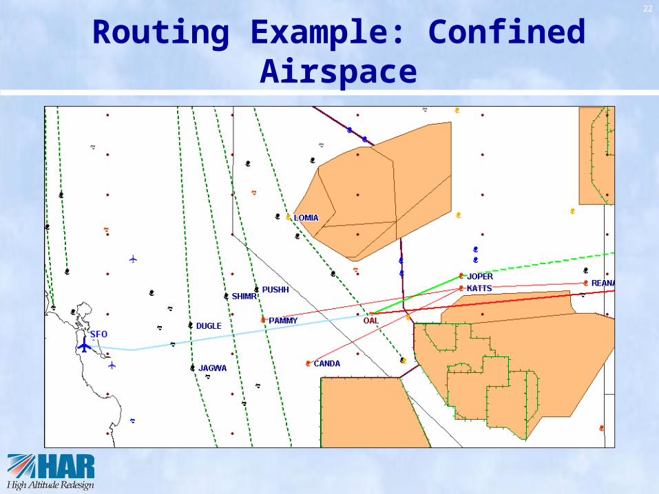
Routing Example: Confined Airspace

23
K D 54 W
Center Identifier
LatitudeFIR
Navigation Reference System
Longitude
Waypoints every 30 minutes of latitude, every 2 degrees longitude

24
NRS - CONUS Fully Populated Density
20 CONUS Centers Coverage @ Every 10’ Latitude & 1°
Longitude
Population = 6,514 points

25
HAR Weather Reroute with NRS

26
Sample Benefits(Initial airspace FL390 and above)
12.6
5.7
12.5
2.1
2.0
20.5
19.0
2.0
Looking at select city pairs, average distance saving of 8 miles per flight
estimated$7M annual savings

27
Analytic Foundation for Decisions
• Each phase supported by modeling– Proof of concept modeling
– Designs modeled for benefits and workability
• After implementation of each phase, post-analysis will:– Validate concept and
design
– Measure benefit Picture by Mary Yee
28
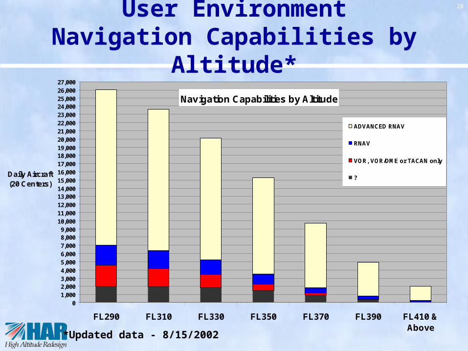
User EnvironmentNavigation Capabilities by Altitude*
Navigation Capabilities by Altitude
01,0002,0003,0004,0005,0006,0007,0008,0009,000
10,00011,00012,00013,00014,00015,00016,00017,00018,00019,00020,00021,00022,00023,00024,00025,00026,00027,000
FL290 FL310 FL330 FL350 FL370 FL390 FL410 &Above
Daily Aircraft (20 Centers)
ADVANCED RNAV
RNAV
VOR, VOR/DME or TACAN only
?
*Updated data - 8/15/2002
29
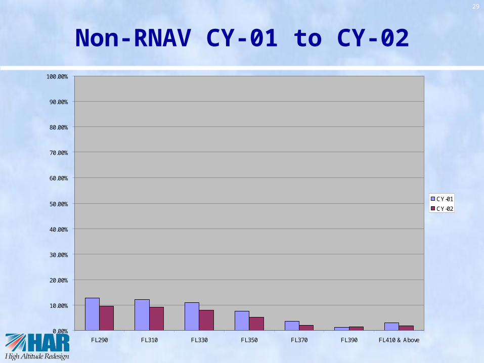
Non-RNAV CY-01 to CY-02
0.00%
10.00%
20.00%
30.00%
40.00%
50.00%
60.00%
70.00%
80.00%
90.00%
100.00%
FL290 FL310 FL330 FL350 FL370 FL390 FL410 & Above
CY-01
CY-02

30
Phase 1 Implementation “Roll out”
Charting Waypoints
May 15, 2003
- Web access to SUA/ATCAA schedule- ATCAA/SUA Avoidance Trials
July 10, 2003
Sept. 23, 2003
Feb. 19, 2004
Chart “Q” Routes
- Initial 11 Q routes rules effective and routes charted – NOTAM NA
Chart NRS Waypoints
-Initiate use of Q Routes Initiate NRR (PTP)
- Full HAR with NRR implemented- Point-to-point for database limited A/C
Sept 4, 2003
- “Improved” ATCAA/SUA Web site

31
Phase 1 Expansion
• Targeting first geographic expansion (2004):– Airspace:
• West of Mississippi: ZLA, ZAB, ZFW, ZHU, ZME• Florida departures/arrivals - to/from the west: ZJX, ZMA
– Initial design complete (FL350 floor altitude)
• Lowering HAR airspace floor– Governing principle - Common floor across HAR airspace– FL350 also planned for 2004– Eventual goal – FL290 and above
• May not be realizable until later phases
• Expansion to Great Lakes Corridor and Northeast linked to NY redesign – 2005/06

32
Summary
• In 2003/04, the initial deployment of High Altitude Redesign will provide benefits through:– RNAV/Parallel RNAV routes
– RNAV waypoint navigation around SUA/ATCAA
– Flexibility in routing: Non-Restrictive Routing (NRR)
– Navigation Reference System (NRS) for point-to-point navigation
• Initial affected airspace:– ZAU, ZMP, ZLC, ZSE, ZOA,
ZDV, ZKC
– NRR FL390 & above

33
Discussion

34
Waypoint Estimates - HAR
Phase Timeframe Centers
Pitch, Catch, SUA / ATCAA, Define
Route NRS
Cummulative Total
1 - Initial CY-03ZSE, ZDV, ZLC, ZOA, ZKC, ZMP, ZAU*
127 513 640
1 - Expansion A CY-04ZLA, ZAB, ZFW, ZHU, ZME, ZMA*, ZJX*
350 281 1,300
1 - Expansion B CY-05ZTL, ZDC, ZNY, ZBW, ZOB, ZID, ZAU**, ZMA**, ZJX**
500 191 2,000
Full U. S. w/NRS Resolution Max.
TBD All 20 Domestic 1,000 6,500 7,500
Notes:* Partial** Remainder
High Altitude Redesign Waypoints - New (approximate)
140 486 626
35
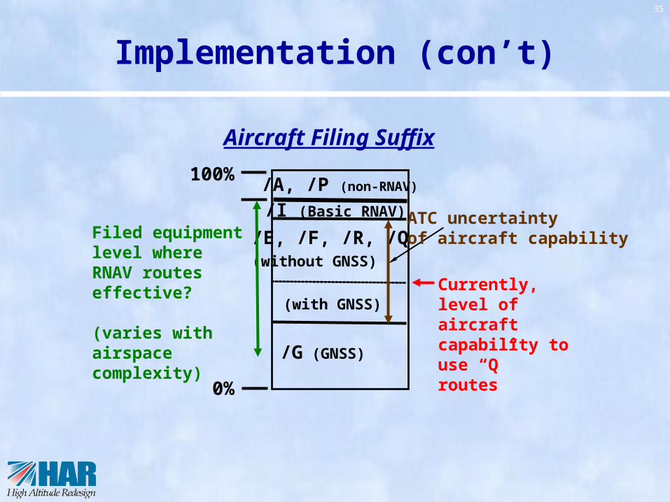
Implementation (con’t)
/A, /P (non-RNAV)
/I (Basic RNAV)
/E, /F, /R, /Q
(without GNSS)
/G (GNSS)
(with GNSS)
100%
0%
Aircraft Filing Suffix
Filed equipment level where RNAV routes effective?
(varies with airspacecomplexity)
Currently, level ofaircraft capability to use “Q” routes
ATC uncertaintyof aircraft capability


