UNESCO-NIGERIA TECHNICAL & VOCATIONAL EDUCATION REVITALISATION PROJECT-PHASE II YEAR1: SEMESTER2, VERSION: 1.THEORTICAL BOOK NATIONAL DIPLOMA IN COMPUTER TECHNOLOGY PC UPGRADE & MAINTENANCE COURSE CODE: COM 126
Transcript
UNESCO-NIGERIA TECHNICAL & VOCATIONAL EDUCATION
REVITALISATION PROJECT-PHASE II
YEAR1: SEMESTER2,
VERSION: 1.THEORTICAL BOOK
NATIONAL DIPLOMA IN
COMPUTER TECHNOLOGY
PC UPGRADE & MAINTENANCE COURSE CODE: COM 126
Week1 ................................................................................................................................. 4 General Objective: .............................................................................................................. 5 To understand the concept of Upgrading and maintenance of PC ...................................... 5 To understand the limitation of a PC and scope of upgrading ............................................ 5 To understand the Technical specifications for upgrading ................................................. 5 Week1Objective(s): ............................................................................................................ 5 Need for computer maintenance ......................................................................................... 5 Harzard threathening computer systems ............................................................................. 5 Remedy and procedures ...................................................................................................... 5 � Concept of Upgrading and Maintenance of a PC ....................................................... 5
Introduction to PC Maintenance ..................................................................................... 5 Typical Hazards Threatening the Normal Operation of a PC. .................................... 7
Viruses and Virus Types ................................................................................................. 9 Virus Types ................................................................................................................. 9 Sources and Spreading of Viruses ............................................................................ 10 Detecting and Removing Viruses ............................................................................. 10
� Week2 Objective(): ................................................................................................... 12 • Understand the need for PC Upgrade ....................................................................... 12 • Recent development in Hardware ............................................................................. 12 • Corresponding software development ...................................................................... 12
The Need for PC Upgrade ............................................................................................. 12 � Week3 Objective(s): ................................................................................................. 15 • Understand the limitation of a PC and Scope for Upgrading ................................... 15 • How to choose Hardware Components for Upgrading ............................................. 15 � ....................................................................................................................................... 15 � Limitations of a PC and Scope for Upgrading computers ........................................ 15 � for 3 or 4 drives—two drives mounted Technical Specifications for PC Upgrading 15 � Week4 Objective(s): ............................................................................................... 20 • How to replace Computer case ................................................................................. 20 • To differentiate between ATX and AT ..................................................................... 20
Case ............................................................................................................................... 20 Case Sizes and Form Factors .................................................................................... 21 Matching the Power Supply to the Case ................................................................... 21 Power Connectors ..................................................................................................... 22
• Objective: How to replace Computer case ................................................................ 24 • To differentiate between ATX and AT ..................................................................... 24
Other Case Connectors and Switches ....................................................................... 24 Thin-Wire Connectors .............................................................................................. 25 AT and ATX Cases and Power Supplies .................................................................. 26
� Week6 Objective(s): ................................................................................................. 28 • How to replace power supply unit ............................................................................ 28 • The power supply form factor................................................................................... 28
Power Supplies.......................................................................................................... 28
TABLE OF CONTENT
A power supply unit (sometimes abbreviated power supply or PSU) is a device or system that supplies electrical or other types of energy to an output load or group of loads. The term is most commonly applied to electrical energy supplies. ....................... 28
General description ..................................................................................................... 29 Electrical power supplies ............................................................................................ 29
Power conversion .................................................................................................... 29 � Week7 Objective(s): ................................................................................................. 32 � How to replace computer Motherboard .................................................................... 32
Replacing the Motherboard: ......................................................................................... 34 � Week8 Objective(s): ................................................................................................. 36 • How to replace computer CPU ................................................................................. 36 � CPU ........................................................................................................................... 36 � Week9 ....................................................................................................................... 39 � Objective(s): .............................................................................................................. 39 � How to replace computer Mass storage unit ............................................................. 39
Hard disk ..................................................................................................................... 39 Mechanics .................................................................................................................... 39 ....................................................................................................................................... 39 Access and interfaces .................................................................................................. 41 Other characteristics .................................................................................................. 42 Manufacturers ............................................................................................................. 44
"Marketing" capacity versus true capacity ......................................................... 45 Hard Drives ............................................................................................................ 49
� Week11 ..................................................................................................................... 52 � Objective(s): .............................................................................................................. 52 � How to replace computer Video Display Unit .......................................................... 52
Electron Gun ............................................................................................................. 54 Focusing System ....................................................................................................... 54 Deflection Coils ........................................................................................................ 55 The Phosphor Coating............................................................................................... 55 Color ......................................................................................................................... 55 Raster Scanning ........................................................................................................ 56 The Color CRT Monitor ........................................................................................... 56
� Week12 How to replace computer Add On Cards .................................................... 64 � ....................................................................................................................................... 64 � Objective(s): .............................................................................................................. 64 � How to replace computer Add On Cards .................................................................. 64 � ....................................................................................................................................... 64 � Input/output ............................................................................................................... 64
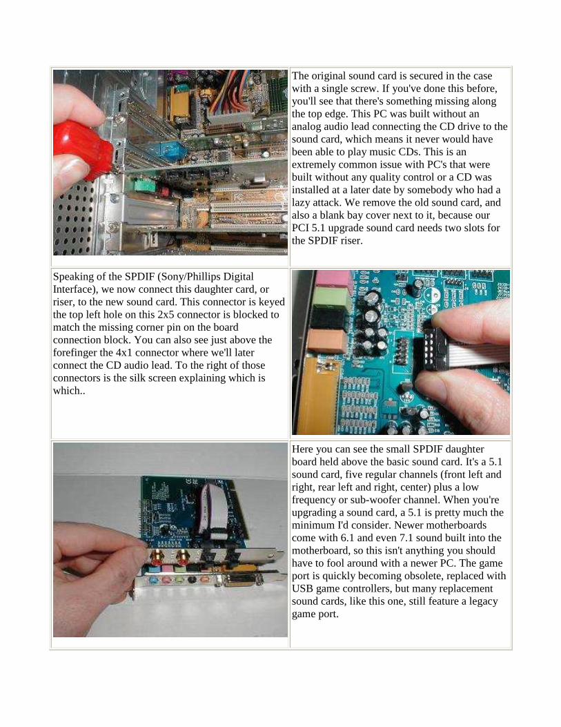
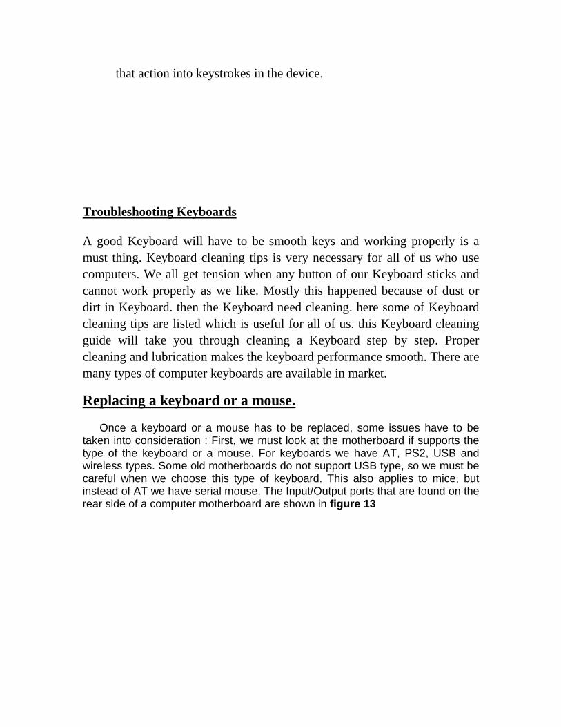
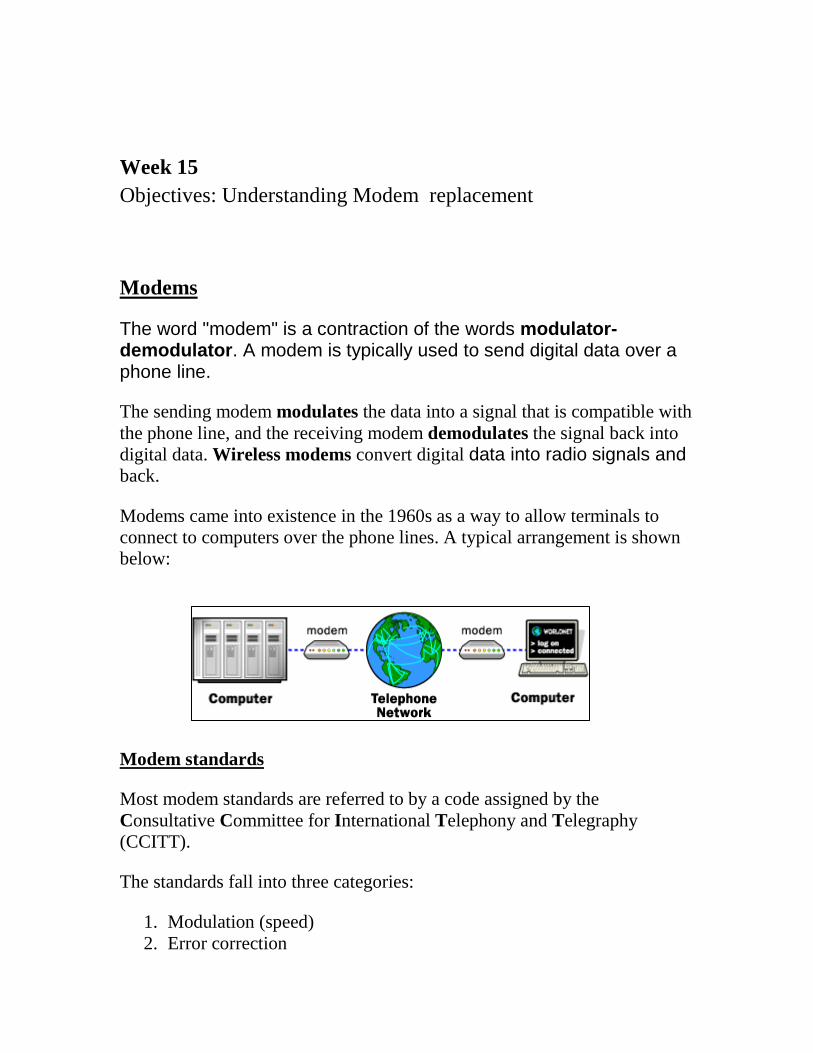
Replacing the Add-On Cards: ....................................................................................... 64 Replacing a VGA card: ............................................................................................. 65
� Objective: How to replace computer Add On Cards ................................................ 68 Replacing a keyboard or a mouse. ................................................................................ 72 Week 15 ........................................................................................................................ 74
To understand the concept of Upgrading and maintenance of PC
To understand the limitation of a PC and scope of upgrading
To understand the Technical specifications for upgrading
Week1Objective(s):
This Week Learning Outcome To Understand:
Need for computer maintenance
Harzard threathening computer systems
Remedy and procedures
� Concept of Upgrading and Maintenance of a PC
Introduction to PC Maintenance
In today's technology-driven world, people depend almost fully on their computers, even for the simplest of tasks. Businesses maintain maximum performance through the use of the most up-to-date technologies; schools keep better management of students through the use of computers and even any person can benefit from these machines.
However, all this efficiency will be lost if computers are not maintained. The following points are just some of the ways to keep your computer clean for maximum performance.
1. When purchasing a computer remember to also purchase dust covers. As the name suggests these will help prevent the build-up of dust on your computer's monitor, central processing unit (CPU), keyboard and mouse.
2. When considering a location for the computer in your home or office, place it in an area that is cool - an air-conditioned room is preferable - or in an area that will not accommodate the easy transmittal of dust to the computer, although this cannot be prevented. Placing the computer near an open window is not advisable, as this will make the computer most vulnerable to the elements, such as wind, dust and rain.
WEEK 1
3. If one is serious about maintaining his computer for optimal performance then he should also seriously consider cleaning the computer on a regular basis. This includes cleaning the monitor, CPU, keyboard and mouse. The vacuuming of the inside of the CPU should also be done to eliminate the build-up of dust on valuable hardware. To undertake this task one should utilize the appropriate tools and have the proper understanding of what is to be done. If this is not clear, then one should utilize the services of a trained technician.
4. Maintaining the optimum performance of one’s computer also includes managing the files on the computer's hard-drive. Keeping files over two years old only means slowing down the speed of that computer. Once a file has been used and will not be used or needed for now, then that file can be deleted or saved onto a floppy disk and removed from the computer's hard-drive. Once the diskette is properly labeled concerning its contents, then that file can be found again. The computer will now have more space for other important documents.
5. Essential to the maintenance of a computer is the utilization of a good virus protection and detection software. Viruses are made daily and without the appropriate software can cause disastrous consequence for a computer's hard-drive.
If you follow these simple guidelines, which are by no means exhaustive, then you will be sure that your computer will run at its best.
Troubleshooting a Hardware Problem 1. Gather as much information from the customer as you can,
including symptoms, error messages, computer history, and action at the time of the failure.
2. Try to reproduce the problem, taking note of any error messages or unusual system activity.
3. Determine whether the problem is hardware or software related. Do this by watching error messages, using the Device Manager, and accessing the hardware using a variety of applications. The remainder of this exercise assumes that the problem is hardware related.
4. Start with the most accessible component in the affected subsystem, making sure that it has power and is properly connected.
5. Check the resources of the device and ensure that a device driver has been loaded for it.
6. Test the device by using it in another computer or by using a known working device in its place.
7. Continue testing and checking all components in the subsystem, working your way into the computer.
8. Finally, test the computer’s most basic components, such as the BIOS, system board, memory, and processor.
Now that you are familiar with basic troubleshooting techniques, try to answer the following Scenario & Solution questions.
Typical Hazards Threatening the Normal Operation of a PC. PC’s are exposed to many hazards which include:
Electrostatic Discharge (ESD) Electrostatic discharge or ESD is caused by the buildup of electrical charge on
one surface that is suddenly transferred to another surface when it is touched. This discharge is actually typically several thousand volts! It just has very little current, which is why it doesn't kill you, unlike those high-tension lines with several thousands volts.
While ESD won't kill you, it can certainly kill your computer components. Especially sensitive to ESD are integrated circuits: processors, memory, cache chips, and expansion cards. You can deal with ESD in two basic ways: reducing its buildup, and draining it away so it cannot cause any damage.
One way to reduce the buildup of ESD is to increase the relative humidity of the room where the computer is located. Static builds up more readily in dry environments than in moist ones; this is why you get zapped much more often in the winter time in northern climates than in the summer. Another way to reduce static is to avoid doing the well-known things that cause it: wearing socks on carpeted floors, etc.
Draining static is usually a simple matter of touching something that is grounded, such as the metal of your case when it is plugged in. This will drain off any static buildup in your body that might cause damage to your components.
Power Fluctuations
The power supply is one of the most important, but also most ignored pieces of a computer. You plug it into the outlet and turn it on, what's the big deal, right? Wrong! The power supply has to work hard to provide a constant and stable level of electricity to the devices in your computer without fluctuations. It has to be strong enough to feed all the devices in your machine, and in some cases it has to be approved to work with certain parts of your PC such as an Athlon CPU.
What if it fails?
A power supply doesn't last forever. Sooner or later they'll fail. They can last all the way from a few months to many years, it all depends on the quality, how hard it has to work, and what conditions it is exposed to (temperature changes, bad electricity, dirt, etc.). The component inside a power supply that is prone to fail first is the fan. It usually starts with a grinding or high-pitched noise that initially disappears a few minutes after
you turn the PC on, but soon gets worse. Once the fan is dead, the hot air is not being properly exhausted from the power supply which causes it to overheat and accelerates its demise. In addition, often the power supply fan also exhausts hot air from the inside of the computer, and if the fan fails, you lose an important part of cooling. Warning: Don't try to replace the power supply fan yourself unless you know what you're doing! It requires some soldering and should only be done by somebody who is familiar and comfortable with such a procedure. I rather recommend replacing the whole unit with a better quality one. When the actual power supply fails, it can exhibit a number of symptoms. You could experience crashes, data corruption, or hardware failure. Another thing that could happen is that when you turn on your PC, the lights and fans come on, but it doesn't boot, because the BIOS cannot verify a sufficient and consistent power flow is established before it continues the Power On Self Test (POST) and the boot process. Or the PC does not boot at all if the power supply is completely dead and nothing happens at all when you push the power button
Power Surges
The power coming from your wall is rated by the electrical company to be within a certain voltage range. The nominal voltage for Bahraini circuits is 240 volts. Due to disturbances, distant lightning strikes, and problems within the electrical grid, on occasion a voltage spike may come down the line. This is a temporary increase of voltage that can last just a few thousandths of a second, but in this time the voltage can increase from 240 to 1,000 volts or even higher.
Most computer power supplies are subjected to many of these surges each year, and like with line noise, most of the better ones can tolerate them to some extent, though it isn't really great for their internal components. In some cases, high voltage surges can disrupt or even damage your computer equipment. In addition, being subjected to many surges over a period of time will slowly degrade many power supply units and cause them to fail prematurely
Backup There are many ways you can unintentionally lose information on a computer. A child playing the keyboard like a piano, a power surge, lightning, floods. And sometimes equipment just fails. If you regularly make backup copies of your files and keep them in a separate place, you can get some, if not all, of your information back in the event something happens to the originals on your computer. Deciding what to back up is highly personal. Anything you cannot replace easily should be at the top of your list. Before you get started, make a checklist of files to back up. This will help you determine what to back up, and also give you a reference list in the event you need to retrieve a backed-up file. Here are some file suggestions to get you started:
• Bank records and other financial information • Digital photographs • Software you purchased and downloaded from the Internet
• Music you purchased and downloaded from the Internet • Personal projects • Your e-mail address book • Your Microsoft Outlook calendar • Your Internet Explorer bookmarks
Backup tool in Windows XP helps you to protect your data in case your hard disk fails or files are accidentally erased. Backup creates a duplicate copy of all the data on your hard disk and then archive it on another storage device, such as a hard disk or a tape.
Viruses and Virus Types A great number of computer problems can be caused by computer
viruses. Effects of a virus could be minor or severe (fatal), and they might be predictable or sporadic. Unfortunately, diagnosing and removing viruses can be difficult, and with the increased information exchange brought on by access to the Internet, viruses are becoming more and more prevalent.
Computer viruses are not caused by corrupted files or internal OS or application flaws. Rather, they are intentionally created programs, the purpose of which is to cause some effect in the computer and replicate themselves to be passed on to other computers. The effect that a virus has on a computer is called its payload. A virus payload could be nondestructive to the computer, meaning that it could merely display a particular message, run a video clip, or change the display colors. However, if a payload is destructive, it can delete files, close running applications, or destroy a drive’s master boot record.
Virus Types Many types of computer infestations are actually not viruses at all. A true
virus is a piece of code that attaches itself to an executable file and is not activated until the executable file is launched. A worm, on the other hand, is a program in itself and does not need to attach itself to a legitimate application in order to run. Viruses are typically more common than worms.
Viruses can be categorized by where they hide themselves. The most common virus type is the file virus. File viruses hide themselves in executable files. When the executable file is run, the virus is activated.
Another virus type is a macro virus. These viruses attach themselves to portions of applications and disguise themselves as macros. A macro is
simply an automated process within an application, such as reading and automatically updating a date field or searching for and formatting specified text.
Another type of virus is a boot sector virus. This type of virus hides itself in the MBR and is activated during startup when the MBR is located and initialized.
Sources and Spreading of Viruses
When a virus is introduced into a computer system, it typically replicates (copies) itself into memory. From there, it can copy itself into other files in the system. This is an intentional behavior, configured by the programmer who created the virus. These copies of the virus can then be spread via floppy disks, downloading files from the Internet, or executing e-mail attachments that launch a host program, such as a word processor.
You can minimize the spread of viruses by using antivirus programs that scan all new files introduced into the computer system. You should scan all files on floppies that have been used in other computers, all e-mail messages with attachments, and all files that you download from the Internet.
Detecting and Removing Viruses Unfortunately, even if you take all the precautions we’ve mentioned, you
are not immune to computer viruses. New viruses are created all the time and could be too new for your antivirus utility to detect. When the computer starts behaving sporadically or begins to unexpectedly crash, close, or launch applications or lose files, you should suspect a virus and begin troubleshooting the problem immediately. If you have an antivirus utility, run it and instruct it to perform a virus scan and removal. A variety of antivirus utilities are available from third parties, such as Norton, Symantec, and McAffee. Windows 2000 includes a native antivirus utility called AVBoot.
In most cases, antivirus utilities work by recognizing and removing specific viruses. They are typically useless against viruses that have been created since the release of the utility itself. For this reason, most third-party virus utility manufacturers keep an up-to-date list of new viruses and offer upgrades via the Internet. It is therefore important that you update you antivirus utility’s capabilities often. Furthermore, if you stay current about new virus types, you are likely to recognize them more quickly if they are introduced into your system.
If an antivirus utility has failed to detect and remove a virus and you suspect the virus is limited to the boot sector, use the FDISK/MBR command. This command will replace the infected MBR with a (hopefully) good copy from a floppy disk.
If you are unable to remove a virus before it has caused fatal damage, you will probably have to reinstall the OS from scratch. It is important in these cases to repartition and reformat the hard drive because viruses could still exist on the drive (especially in the boot sector).
Use the following Scenario & Solution questions and answers to test your knowledge of the virus concepts discussed in the previous sections.
� Week2 Objective():
• Understand the need for PC Upgrade • Recent development in Hardware • Corresponding software development
The Need for PC Upgrade
As a rule, one probably wouldn’t build a new PC or upgrade an older one unless he/she is getting at least a factor of three or four more in performance at a reasonable cost. So, for example, a 600 MHz system wouldn’t be changed until reasonably-priced systems could be made or purchased that run at 1.8 GHz to 2.4 GHz or faster. A 2 GHz system wouldn’t be replaced until a reasonably-priced system could be purchased that runs at 6 GHz or higher. Remember, the longer you can delay upgrading, the more you’ll get for your money when you finally do upgrade!
It won’t be a good idea to upgrade from a 1.7 GHz system to a 2 GHz one.
The only exception is when software you want to run demands a better system. Maybe, you want to play a video-intensive game, and your system just won’t cut it. Or, maybe, you decide you want to study database development and you install Oracle 9i on your computer, but find you need a faster PC. Possibly, you decide to produce music videos on your PC, and you find that the best video editing software runs much better on a faster system. But, unless the software you desire to run demands a faster, better system, you’ll probably do well to postpone an upgrade or building a new system until you can get a factor of three in better overall performance.
One of the most items to be continuously upgraded is the RAM , then comes the CPU and sometimes the mainboard, video card or hard disk.
Sometimes we also need to upgrade the Software in our PC. That means, we install a newer version of a specific operating system or other applications. Sometimes, this becomes a must since some newer applications won’t run under an old operating system and also some files of newer versions of applications won’t run under older versions of the same application. Examples of what we are talking about are the following: Office2003 can’t be installed in MS Windows98 or previous versions. Also, a PDF file generated with a new version of Adobe Acrobat Writer won’t be correctly read using an earlier version of Adobe Acrobat Reader software.
Recent advancement
CPU speed Even when CPUs are the same, clock speed (measured in MHz) effects per-formance. For example, a PC with a “classic” Pentium 166MHz CPU will run faster than a PC with a “classic” Pentium 120MHz CPU. CPU upgrade potential Because CPUs have a finite processing limit, it follows that upgrading the CPU will improve system processing. Although this is great in theory, you can’t just place any old CPU in the CPU socket and expect the motherboard to work. Any motherboard is limited to using a handful of current CPU versions. For example, Intel’s recent AN430TX motherboard supports Pentium processors at 90, 100, 120, 133, 150, 166, and 200MHz, as well as Pentium MMX processors running at 166, 200, and 233MHz. By comparison, Intel’s new NX440LX motherboard supports Pentium II mi-croprocessors operating at 233, 266, and 300MHz. Changing the processor type and speed requires changes in several jumper settings. Memory slots The sheer amount of memory that can be added to the motherboard will indirectly affect system performance because of a reduced dependence on virtual memory (a swap file on the hard drive). Memory is added in the form of SIMMs (Single In-line Memory Modules) or DIMMs (Dual In-line Memory Modules). Motherboards that can accept more or larger-capacity memory modules will support more memory. It is not un-common today to find motherboards that will support 512MB of RAM (equal to the stor-age capacity of older hard drives). Memory types The type of memory will also have an effect on motherboard (and sys-tem) performance. Faster memory will improve system performance. DRAM remains the slowest type of PC memory, and is usually used in older systems or video boards. EDO RAM is faster than ordinary DRAM, and is now commonplace in PCs. SDRAM is mea-surably faster than EDO RAM, and is appearing in high-to-mid-range PC applications. By the time you read this book, SDRAM should be common. RDRAM is an emerging mem-ory type that should gain broad acceptance in the next few years. It is not necessary for you to understand what these memory types are yet; just understand that memory perfor-mance and system performance are related. Cache memory Traditional RAM is much slower than a CPU—so slow that the CPU must insert pauses (or “wait states”) for memory to catch up. Cache is a technique of im-proving memory performance by keeping a limited amount of frequently used information in VERY fast cache RAM. If the needed information is found, the CPU reads the cache at full speed (and performance is improved because less time is wasted). By making the
cache larger, it is possible to hold more “frequently used” data. Older motherboards used from 128KB to 256KB of cache. Current motherboards use 512KB to 1MB of cache RAM. Chipsets A chipset is a set of highly optimized, tightly inter-related ICs which, taken to-gether, handle virtually all of the support functions for a motherboard. As new CPUs and hardware features are crammed into a PC, new chipsets must be developed to implement those functions. For example, the Intel 430HX chipset supports the Pentium CPU and EDO RAM. Their 430VX chipset supports use of the Pentium CPU, the Universal Serial
� Week3 Objective(s):
• Understand the limitation of a PC and Scope for Upgrading • How to choose Hardware Components for Upgrading
�
� Limitations of a PC and Scope for Upgrading computers
Upgrading is a term used to describe updating a software program or adding a new hardware. Software upgrade allows a user to get the latest version of a software program at a discounted price and not have to purchase the full product. For example, a user running Microsoft Windows 95 could purchase the Microsoft Windows 98 upgrade for a low price when compared to the full version of Windows 98. Below is a few reasons and benefits of upgrading your software products to the latest version.
A hardware upgrade often involves removing an old hardware device and replacing it with a new hardware device. For example, replacing an 8MB PCI video card with a 32MB AGP video card would be considered an upgrade. A hardware upgrade such as a memory upgrade may not require a user to remove the memory from the computer because of the availability of additional expansion slots. Below is a few reasons and benefits a user should expect to see when upgrading a hardware device.
1. Performance increase. The majority of the hardware upgrades performed are done to increase the performance of the computer.
2. Capacity increase. Users may upgrade or add a new device to increase the overall capacity of the computer. For example, adding a new hard drive to allow the computer to store more information. Or increase the memory to increase the ability of what programs can be opened and also at the same time increase the performance.
3. Compatibility . A user may upgrade one or more components in their computer to be able to run or use a software program.
as long as the power supply is plugged in. However, because you are strongly urged to protect yourself by unplugging the power supply ac, do not rely on the chassis to discharge
you. Grounding also prevents a serious shock or fire hazard if ac should come in contact with the metal case. The enclosure also limits the PC’s expansion capacity. Average-sized desktop enclo-sures typically offer room for motherboards with 6 to 8 expansion slots, and provide space
� for 3 or 4 drives—two drives mounted Technical Specifications for PC Upgrading
When someone wants to do a system upgrade, he must think of a systematic procedure to do the process. This involves the following:
1- to open the case of the PC.
When someone wants to upgrade a PC the first step will be to open the case and inspect what’s inside there. Some cases are opened using Philips screwdrivers, others using Flat. When the case is opened may be the following picture or something like it will show up. The computer case holds all the internal parts of your PC. Many case variations are available including tower cases, mid-tower cases, and desktop models. The case pictured in Figure 4 is a mid-tower ATX case .
Figure 4: An ATX case with all components inside
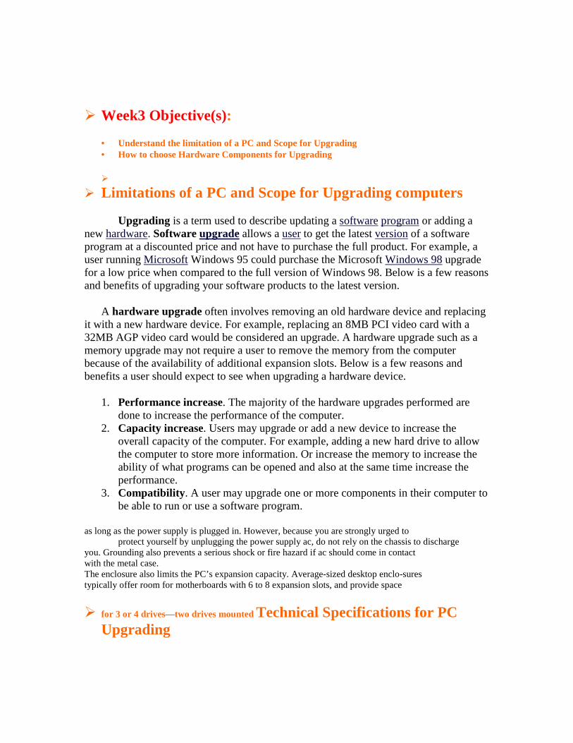
2- How to make a list of components to upgrade: As stated before, we may upgrade the RAM, Processor, VGA card, Mainboard, Hard disk or more than one of them. So we must be specific when choosing what to upgrade. Here are pictures of these components:
The mainboard
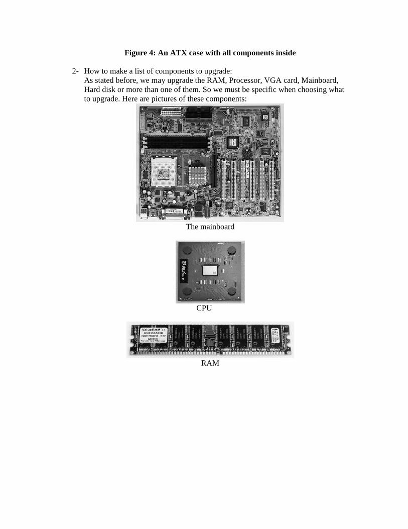
CPU
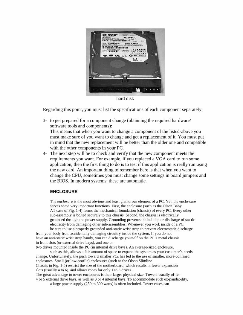
RAM
hard disk
Regarding this point, you must list the specifications of each component separately. 3- to get prepared for a component change (obtaining the required hardware/
software tools and components): This means that when you want to change a component of the listed-above you must make sure of you want to change and get a replacement of it. You must put in mind that the new replacement will be better than the older one and compatible with the other components in your PC.
4- The next step will be to check and verify that the new component meets the requirements you want. For example, if you replaced a VGA card to run some application, then the first thing to do is to test if this application is really run using the new card. An important thing to remember here is that when you want to change the CPU, sometimes you must change some settings in board jumpers and the BIOS. In modern systems, these are automatic. ENCLOSURE The enclosure is the most obvious and least glamorous element of a PC. Yet, the enclo-sure serves some very important functions. First, the enclosure (such as the Olson Baby AT case of Fig. 1-4) forms the mechanical foundation (chassis) of every PC. Every other sub-assembly is bolted securely to this chassis. Second, the chassis is electrically grounded through the power supply. Grounding prevents the buildup or discharge of sta-tic electricity from damaging other sub-assemblies. Whenever you work inside of a PC, be sure to use a properly grounded anti-static wrist strap to prevent electrostatic discharge
from your body from accidentally damaging circuitry inside the system. If you do not have an anti-static wrist strap handy, you can discharge yourself on the PC’s metal chassis in front slots (or external drive bays), and one or two drives mounted inside the PC (in internal drive bays). An average-sized enclosure,
such as this, allows a fair amount of space to expand the system as your customer’s needs change. Unfortunately, the push toward smaller PCs has led to the use of smaller, more-confined enclosures. Small (or low-profile) enclosures (such as the Olson Slimline Chassis in Fig. 1-5) restrict the size of the motherboard, which results in fewer expansion slots (usually 4 to 6), and allows room for only 1 to 3 drives. The great advantage to tower enclosures is their larger physical size. Towers usually of-fer 4 or 5 external drive bays, as well as 3 or 4 internal bays. To accommodate such ex-pandability,
a large power supply (250 to 300 watts) is often included. Tower cases can
also fit larger motherboards, which tend to support a greater number of expansion slots. The higher power demands of a tower system result in greater heat generation. Towers compensate for heat by providing one or more internal fans to force air into the enclosure. If a second internal fan is included, it generally works in conjunction with the first fan to exhaust heated air. For example, you’ll often find tower systems with two fans—one in the lower front to force in cooler air and one in the upper rear to exhaust heated air. If only one
fan is used, it will usually be located in the upper rear of the chassis to exhaust heated air.
� Week4 Objective(s):
• How to replace Computer case • To differentiate between ATX and AT
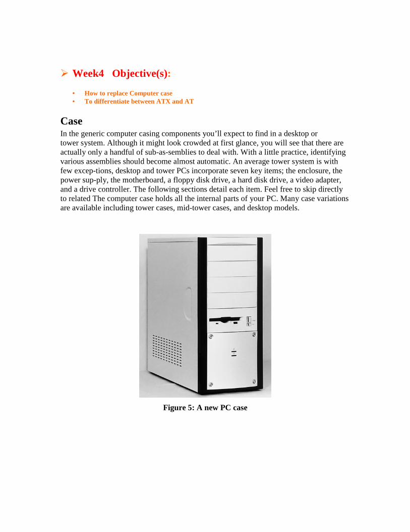
Case In the generic computer casing components you’ll expect to find in a desktop or tower system. Although it might look crowded at first glance, you will see that there are actually only a handful of sub-as-semblies to deal with. With a little practice, identifying various assemblies should become almost automatic. An average tower system is with few excep-tions, desktop and tower PCs incorporate seven key items; the enclosure, the power sup-ply, the motherboard, a floppy disk drive, a hard disk drive, a video adapter, and a drive controller. The following sections detail each item. Feel free to skip directly to related The computer case holds all the internal parts of your PC. Many case variations are available including tower cases, mid-tower cases, and desktop models.
Figure 5: A new PC case
Case Sizes and Form Factors
Most chosen cases are tower or mid-tower. Most builders also prefer the ATX form factor. Smaller cases are said to have a smaller footprint and they save space. However, larger cases offer more room for expansion options. And, working inside a larger case is somewhat easier.
It is recommended choosing a quality mid-tower or full-tower ATX case for your first PC build. These cases are designed to be paired with any ATX mainboard.
Unless mainboard manufacturers change the basic ATX case style in the future, your case should last a long time and serve you through several years of mainboard upgrades. Choosing a quality case is a good investment.
Building your own PC and using standard components will give you maximum upgrade potential. Choose the ATX form factor for your case.
With a standard ATX case, you’ll have the fullest range of upgrade options to newer, more powerful mainboards. This standardization of components, which allows easy upgrades, is one advantage of building a PC rather than buying one.
Matching the Power Supply to the Case
Power supplies come with most cases today (Figure 6). The power supply has many power connectors to power the mainboard, hard drives, CD-RW drives, and other components.
Figure 6: Inside of a new PC case
Be sure that your case and power supply match the type of mainboard you want to install. This usually means purchasing an ATX style mainboard and case. Be sure your case supports a full ATX mainboard.
Power Connectors
Most mainboards today are ATX style. You can identify an ATX power supply and case by looking for an ATX power connection. See Figure 7.
Figure 7: ATX power connector
Most power connectors today are made so that they can only be plugged in one way. This connector provides power to the ATX mainboard.
Most important power connectors, such as the twenty-pin ATX power connection, are designed so that they can only be plugged in one way. This prevents plugging the connector in the wrong way and causing damage to components by putting too high a voltage on a pin that isn’t designed to take it.
Newer ATX power supplies also have a special four-pin power connector (Figure 8), which is used with Pentium 4 mainboards. If you’re installing an AMD Athlon, you won’t need this special four-pin connector. Just leave it disconnected.
Figure 8: The special 4-pin Pentium 4 power header
If you’re building a Pentium 4 system, be sure your power supply has the necessary 4-pin power supply connector in addition to the standard ATX power supply connector. All newer cases will have it. When in doubt, ask if the ATX case is approved for the Pentium 4.
If your power supply ever needs replacement, you can keep the case and just purchase a new ATX power supply. As a general rule, most cases will have several extra power connectors which will remain unused when your system is built. Just tuck the unneeded power connectors out of the way when you close up your PC case. They don’t all need to be connected to something. If you later add another hard drive or a DVD player, for example, you’ll use one of the remaining power connectors to supply power to it.
If you run out of power connectors (unlikely), you can purchase Y Splitters which are small cables designed to give you more than one power connector from one existing power supply connection. It’s just like purchasing a power strip that plugs into your wall outlet and provides six or eight new outlet sockets. Cyberguys.com is one source of different types of Y adapters.
Similarly, if you find some component needs a unique power connection that isn’t provided for from your existing power supply connections, you can purchase a Y splitter or an adapter which will give you the specific connector you need. This is relatively rare as most modern power supplies offer a cornucopia of power connectors. There are also extension adapters which give power supply cables more length. You probably won’t need these either, unless you install a new power supply in a large case.
WEEK5
• Objective: How to replace Computer case • To differentiate between ATX and AT
Other Case Connectors and Switches
Other connectors from the case don’t supply power, but they connect the front panel of the computer case to the mainboard. These connectors are thin wires with little connectors on the ends that plug into pins on the mainboard (Figure 9).
Figure 9: Thin-wire connectors connect the front of the PC case to the mainboard
For example, to turn the computer on and off, there is an on-off switch on the case. The small Power SW wire connects the power button on the case to the mainboard to let the mainboard know when you want the PC to turn on or off. This small two-pin connector may be plugged-in in either direction on the mainboard.
Basic switches can usually be installed in either direction, because they are designed to either open or close a circuit. So, the orientation of the two pins doesn’t usually matter.
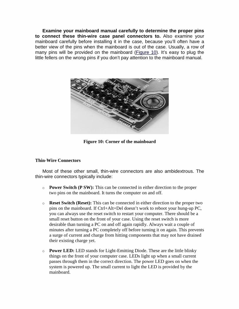
Examine your mainboard manual carefully to determine the proper pins to connect these thin-wire case panel connectors to. Also examine your mainboard carefully before installing it in the case, because you’ll often have a better view of the pins when the mainboard is out of the case. Usually, a row of many pins will be provided on the mainboard (Figure 10). It’s easy to plug the little fellers on the wrong pins if you don’t pay attention to the mainboard manual.
Figure 10: Corner of the mainboard
Thin-Wire Connectors
Most of these other small, thin-wire connectors are also ambidextrous. The thin-wire connectors typically include:
o Power Switch (P SW): This can be connected in either direction to the proper two pins on the mainboard. It turns the computer on and off.
o Reset Switch (Reset): This can be connected in either direction to the proper two pins on the mainboard. If Ctrl+Alt+Del doesn’t work to reboot your hung-up PC, you can always use the reset switch to restart your computer. There should be a small reset button on the front of your case. Using the reset switch is more desirable than turning a PC on and off again rapidly. Always wait a couple of minutes after turning a PC completely off before turning it on again. This prevents a surge of current and charge from hitting components that may not have drained their existing charge yet.
o Power LED: LED stands for Light-Emitting Diode. These are the little blinky things on the front of your computer case. LEDs light up when a small current passes through them in the correct direction. The power LED goes on when the system is powered up. The small current to light the LED is provided by the mainboard.
o HD LED: This front case panel LED blinks when the hard drive is active. If this connector is installed in the wrong direction, your computer will work fine except your hard drive LED probably won’t light up or it will remain on rather than blinking with activity. If you notice that it isn’t working, just reorient the connector.
o Speaker connection: This connects the small case speaker to the mainboard.
Those front panel connectors that aren’t ambidextrous (such as the hard drive LED, which lights up on the front panel to show activity on the hard drive) won’t damage your system if they are hooked up backward. These thin-wire connectors to the mainboard aren’t supplying power to the mainboard.
AT and ATX Cases and Power Supplies
The ATX power supply also typically provides a small current to the mainboard even when the computer is off. So you should always disconnect the power supply cord before upgrading your PC or working on its internals. Or, turn off your power strip or uninterruptible power supply (UPS) that your computer is attached to before working on it. The ATX power supply also usually provides a power switch at the back of the PC, labeled “O” for off and “1” for on. But, it’s best if the power is off before reaching the PC power cord.
ATX mainboards often have an LED on the mainboard which will remain lighted all the time, even when the PC is turned off. This lets you know there is power to the mainboard. And, hopefully, reminds you to unplug the power cord before proceeding further! Inserting and removing parts on an ATX mainboard that has power can damage components.
Plugging your PC into the wall outlet or UPS will be the last step in building your PC. I recommend your purchase a UPS to protect your new PC from electrical surges. At today’s prices, a UPS is a great purchase. If power fails, the UPS will give you time to shut down your system properly. Do not plug in your power supply cord to an outlet until you have assembled your PC.
The older AT case style is outdated. Connections from the power supply differ between the ATX and AT style. Older AT cases will not work with a newer ATX mainboard. (You can buy adapters to convert AT power to ATX power. But, I’d recommend against this, because with your newer components, you’ll probably want a bigger and more stable power supply anyway.)
Your case and mainboard will probably be based upon the ATX style. But, if you ever need to repair or upgrade an older AT style, it’s very important to be sure that the two AT power connectors are connected with the black wires toward the middle of the two connectors. This is one of the few power connectors that can be assembled incorrectly causing damage. You don’t need to worry about
this with the ATX style cases. If you’re working with new PCs, you’ll probably never use the older AT style power connectors.
� Week6 Objective(s):
• How to replace power supply unit • The power supply form factor
Power Supplies The power supply shown below, typically located at the back of the computer’s
interior, has several very important functions. It is responsible for converting the alternating current (AC) voltage from wall outlets into the direct current (DC) voltage that the computer requires. The power supply accomplishes this task through a series of switching transistors, which gives rise to the term switching mode power supply. Another function of the power supply is to ensure that the computer receives the proper amount of voltage. Typical North American wall outlets generate about 110–120 vAC (volts AC). However, computers require comparatively smaller voltages—±12, ±5, or ±3.3 vDC (volts DC). The computer’s power supply removes the excess voltage and dissipates it in the form of heat. This build-up of heat can cause computer components (including the power supply itself) to fail. Therefore, the power supply has a built-in fan that draws air in from outside the computer case and cools off the components inside.
A power supply unit (sometimes abbreviated power supply or PSU) is a device or system that supplies electrical or other types of energy to an output load or group of loads. The term is most commonly applied to electrical energy supplies.
The power supply is the silver box that is usually located in the rear right quarter of the en-closure. Ac enters the supply through the ac line cord, which is connected at the rear of the enclosure. A supply then produces a series of dc outputs that power the motherboard and drives. The importance of a power supply is easy enough to understand, but its implica-tions for system integrity and expandability might not be as obvious. Power supplies sustain a great deal of electrical stress in normal everyday operation. The conversion of ac into dc results in substantial heat, which is why so many power sup-plies are equipped with a cooling fan. Surges, spikes, and other anomalies that plague ac power distribution (especially in underdeveloped regions of the world) also find their way into PC power supplies, where damage can occur. The quality of a power supply’s design and components and design dictate how long it will last in operation. A quality supply will resist power problems and tolerate the rigors of normal operation, but a sub-standard sup-ply can fail spontaneously after only a few months of operation. When replacing or up-grading a power supply, be sure to choose a reliable model. Power supplies also limit a system’s expandability. Every element used in the PC re-quires a certain amount of power (marked W for watts). The supply must be capable of producing enough power to adequately meet the system’s demand. An under-powered supply (typical in low-profile systems) or a supply overloaded by excessive expansion (which frequently occurs in
tower systems) might not be able to support the power needs of the system. Inadequate power results in very strange system behavior such as unpre-dictable system lockups, random memory faults, or disk-access problems. When replac-ing a power supply, be certain that the new supply can provide at least as much power as the supply being replaced. When upgrading a supply, choose a supply that offers at least 50 watts more than the original supply. Power supply assemblies are generally regarded as extremely safe because it is virtually impossible to come into contact with exposed high-energy circuitry. Still, exercise care and common sense whenever working with a running power supply.
General description
The complete range of power supplies is very broad, and could be considered to include all forms of energy conversion from one form into another. Conventionally though, the term is usually confined to electrical or mechanical energy supplies. Constraints that commonly affect power supplies are the amount of power they can supply, how long they can supply it for without needing some kind of refueling or recharging, how stable their output voltage or current is under varying load conditions, and whether they provide continuous power or pulses.
Electrical power supplies
This term covers the mains power distribution system together with any other primary or secondary sources of energy such as:
• Batteries • Chemical fuel cells and other forms of energy storage systems • Solar power • Conversion of another form of electrical power into the desired form (typically
converting 120 or 240 volt alternating current supplied by a utility company (see electricity generation) into low-voltage direct current for electronic devices); see switched-mode power supply, linear regulator, rectifier, inverter (electrical) Generators or alternators (particularly useful in vehicles of all shapes and sizes, where the engine has rotational power to spare, or in semi-portable units containing an internal combustion engine and a generator)(For large-scale power supplies, see electricity generation.)Low voltage, low power dc power supply units are commonly integrated with the devices they supply, such as computers and household electronics.
Power conversion
The term "power supply" is sometimes restricted to those devices that convert some other form of energy into electricity (such as solar power and fuel cells and generators). A more accurate term for devices that convert one form of electric power into another form of electric power (such as transformers and linear regulators) is power converter.
A Typical Power Supply
The ATX power supply also typically provides a small current to the mainboard even when the computer is off. So you should always disconnect the power supply cord before upgrading your PC or working on its internals. Or, turn off your power strip or uninterruptible power supply (UPS) that your computer is attached to before working on it. The ATX power supply also usually provides a power switch at the back of the PC, labeled “O” for off and “1” for on. But, it’s best if the power is off before reaching the PC power cord.
ATX mainboards often have an LED on the mainboard which will remain lighted all the time, even when the PC is turned off. This lets you know there is power to the mainboard. And, hopefully, reminds you to unplug the power cord before proceeding further! Inserting and removing parts on an ATX mainboard that has power can damage components.
Plugging your PC into the wall outlet or UPS will be the last step in building your PC. I recommend your purchase a UPS to protect your new PC from electrical surges. At today’s prices, a UPS is a great purchase. If power fails, the UPS will give you time to shut down your system properly. Do not plug in your power supply cord to an outlet until you have assembled your PC.
The older AT case style is outdated. Connections from the power supply differ between the ATX and AT style. Older AT cases will not work with a newer ATX mainboard. (You can buy adapters to convert AT power to ATX power. But, I’d recommend against this, because with your newer components, you’ll probably want a bigger and more stable power supply anyway.)
Your case and mainboard will probably be based upon the ATX style. But, if you ever need to repair or upgrade an older AT style, it’s very important to be sure that the two AT power connectors are connected with the black wires toward the middle of the two connectors. This is one of the few power connectors that can be assembled incorrectly causing damage. You don’t need to worry about this with the ATX style cases. If you’re working with new PCs, you’ll probably never use the older AT style power connectors.
� Week7 Objective(s): � How to replace computer Motherboard
Mother Board
A motherboard is a printed circuit board used in a personal computer. It is also known as the mainboard and occasionally abbreviated to mobo or MB. The term mainboard is also used for the main circuit board in this and other electronic devices.
A typical motherboard provides attachment points for one or more of the following: CPU, graphics card, sound card, hard disk controller, memory (RAM), and external peripheral devices.
All of the basic circuitry and components required for a computer to function sit either directly on the motherboard or in an expansion slot of the motherboard. The most important component on a motherboard is the chipset which consists of two components or chips known as the Northbridge and Southbridge. These chips determine, to an extent, the features and capabilities of the motherboard.
The remainder of this article discusses the state of the so-called "IBM compatible PC" motherboard in the early 2000s. It contains the chipset, which controls the operation of the CPU, the PCI, ISA, AGP, and PCI Express expansion slots, and (usually) the IDE/ATA controller as well. Most of the devices that can be attached to a motherboard are attached via one or more slots or sockets, although some modern motherboards support wireless devices using the IrDA, Bluetooth, or 802.11 (Wi-Fi) protocols
The motherboard (also known as the main board, system board, backplane board, or pla-narboard) holds the majority of a computer’s processing power. As a minimum, a moth-erboard contains the system CPU, math co-processor (now routinely built into the CPU), clock/timing circuits, RAM, cache, BIOS ROM, serial port(s), parallel port, and expansion slots. Each portion of the motherboard is tied together with interconnecting logic cir-cuitry. Some advanced motherboards also include circuitry to handle drive and video in-terfaces. You can identify the motherboard easily as shown in Fig. 1-6—it is the single large printed circuit board located just off of the enclosure’s base. As you might expect, it is the motherboard more than any other element of the PC that defines the performance (and performance limitations) of any given computer system. This is the reason why motherboard upgrades are so popular, and often provide such stun-ning improvements to a PC. Let’s break motherboard limitations down into the following nine categories:
CPU type A CPU is responsible for processing each instruction and virtually all of the data needed by the computer (whether the instruction is for BIOS, the operating system, or an application). The type of CPU limits the PC’s overall processing power. For example, a PC with a Pentium II CPU runs Windows 95 much better than a PC with a “classic” Pentium CPU. Also, a Pentium MMX CPU will generally handle graphics-intensive ap-plications better than a “classic” Pentium CPU.
CPU speed Even when CPUs are the same, clock speed (measured in MHz) effects per-formance. For example, a PC with a “classic” Pentium 166MHz CPU will run faster than a PC with a “classic” Pentium 120MHz CPU. CPU upgrade potential Because CPUs have a finite processing limit, it follows that upgrading the CPU will improve system processing. Although this is great in theory, you can’t just place any old CPU in the CPU socket and expect the motherboard to work. Any motherboard is limited to using a handful of current CPU versions. For example, Intel’s recent AN430TX motherboard supports Pentium processors at 90, 100, 120, 133, 150, 166, and 200MHz, as well as Pentium MMX processors running at 166, 200, and 233MHz. By comparison, Intel’s new NX440LX motherboard supports Pentium II mi-croprocessors operating at 233, 266, and 300MHz. Changing the processor type and speed requires changes in several jumper settings. Memory slots The sheer amount of memory that can be added to the motherboard will indirectly affect system performance because of a reduced dependence on virtual memory (a swap file on the hard drive). Memory is added in the form of SIMMs (Single In-line Memory Modules) or DIMMs (Dual In-line Memory Modules). Motherboards that can accept more or larger-capacity memory modules will support more memory. It is not un-common today to find motherboards that will support 512MB of RAM (equal to the stor-age capacity of older hard drives). Memory types The type of memory will also have an effect on motherboard (and sys-tem) performance. Faster memory will improve system performance. DRAM remains the
slowest type of PC memory, and is usually used in older systems or video boards. EDO RAM is faster than ordinary DRAM, and is now commonplace in PCs. SDRAM is mea-surably faster than EDO RAM, and is appearing in high-to-mid-range PC applications. By the time you read this book, SDRAM should be common. RDRAM is an emerging mem-ory type that should gain broad acceptance in the next few years. It is not necessary for you to understand what these memory types are yet; just understand that memory perfor-mance and system performance are related. Cache memory Traditional RAM is much slower than a CPU—so slow that the CPU must insert pauses (or “wait states”) for memory to catch up. Cache is a technique of im-proving memory performance by keeping a limited amount of frequently used information in VERY fast cache RAM. If the needed information is found, the CPU reads the cache at full speed (and performance is improved because less time is wasted). By making the cache larger, it is possible to hold more “frequently used” data. Older motherboards used from 128KB to 256KB of cache. Current motherboards use 512KB to 1MB of cache RAM.
Chipsets A chipset is a set of highly optimized, tightly inter-related ICs which, taken to-gether, handle virtually all of the support functions for a motherboard. As new CPUs and hardware features are crammed into a PC, new chipsets must be developed to implement those functions. For example, the Intel 430HX chipset supports the Pentium CPU and EDO RAM. Their 430VX chipset supports use of the Pentium CPU, the Universal Serial
Replacing the Motherboard:
Several different upgrades can boost your PC's performance, but for a real jump for your old PC, nothing beats a full motherboard upgrade. A new motherboard, coupled with a high-speed processor and a generous amount of RAM, can dramatically improve system performance. (Figure 11) shows a Pentium IV motherboard.
Figure 11: a Pentium IV motherboard
Most computers made in the past three years have cases that require a motherboard with an ATX form factor. If you're replacing an ATX motherboard, you can choose from a wide variety of boards, differing mainly in the processor types and speeds they support. Your best bet is to choose the processor you want and then purchase a motherboard that supports it.
The most important thing to think about the new board is its upgradeability, i.e. to what speed it can accept a CPU, how many MB’s of RAM does it take and so.
Also when you want to purchase a new mainboard you must know if it is compatible with your CPU and RAM, because some boards do not support some types of CPU’s and RAM’s
� Week8 Objective(s):
• How to replace computer CPU
Central Processing Unit Most computer components are designed to perform only one or a limited number of functions, and they only do so when it is specifically requested of them. The device responsible for organizing the actions of these components is the processor, also referred to as the central processing unit, or CPU. As the “brain” of the computer, the processor receives requests from you, the user; determines the tasks needed to fulfill the request; and translates the tasks into signals that the required component(s) can understand. The processor also does math and logic calculations.
central processing unit (CPU) refers to part of a computer that interprets and carries out, or processes, instructions contained in the software. The term processor can refer to a CPU as well; see processor (disambiguation) for other uses of this term. A microprocessor is a common type of CPUs that are manufactured on a single integrated circuit. Most, but not all, modern CPUs are microprocessors. Historically, a single-processor CPU was a set of refrigerator-sized racks of electronics very similar to today's racks of processors in a server farm. One notable problem which continues to the current day is cooling the electronics which had to run at high speeds, which requires the dissipation of wasted energy, or heat.
� CPU
central processing unit (CPU) refers to part of a computer that interprets and carries out, or processes, instructions contained in the software. The term processor can refer to a CPU as well; see processor (disambiguation) for other uses of this term. A microprocessor is a common type of CPUs that are manufactured on a single integrated circuit. Most, but not all, modern CPUs are microprocessors. Historically, a single-processor CPU was a set of refrigerator-sized racks of electronics very similar to today's racks of processors in a server farm. One notable problem which continues to the current day is cooling the electronics which had to run at high speeds, which requires the dissipation of wasted energy, or heat. CPU SOCKETS Another important idea in CPU development and upgradeability is the concept of “sockets.” Each generation of CPU uses a different number of pins (and pin assignments), so a different physical socket must be used on the motherboard to accommodate each new generation of processor. Early CPUs were not readily interchangeable, and upgrading a CPU typically meant upgrading the motherboard. With the introduction of the i486 CPUs, the notion of “OverDrive” processors became popular—replacing an existing CPU with a pincompatible
replacement processor that operated at higher internal clock speeds to enhance system performance. Table 11-2 shows that the earliest “sockets” were designated Socket 1 for early 486SX and DX processors (you can see the corresponding sockets illustrated in Fig. 11-3). As CPUs advanced, socket types proliferated to support an ever-growing selection of compatible processors. Today, the most common type of socket is Socket 7. Socket 7 motherboards support most Pentium-type processors (i.e., Intel Pentium, Intel Pentium MMX, AMD K5, AMD K6, Cyrix 6x86, and Cyrix 6x86MX). By setting the proper clock speed and multiplier, a Socket 7 motherboard can support a variety of Pentium-type CPUs without making any
Comparison of major CPU socket configurations Socket1 To Socket8
The Intel CPUs There is little doubt that Intel Corporation has been a driving force behind the personal computer revolution. Each new generation of microprocessor represents not just mediocre improvements in processing speed, but technological leaps in execution efficiency, raw speed, data throughput, and design enhancements (such as dynamic execution). This part of the chapter provides a historical overview of Intel microprocessors and compares their characteristics. You can find a breakdown of Intel CPU specifications in Table 11-3. 8086/8088 (1978/1979) The 29,000-transistor 8086 marked the first 16-bit microprocessor—that is, there are 16 data bits available from the CPU itself. This immediately offered twice the data throughput of earlier 8-bit CPUs. Each of the 24 registers in the 8086/8088 is expanded to 16 bits, rather than just 8. Twenty address lines allow direct access to 1,048,576 bytes (1MB) of external system memory. Although 1MB of RAM is considered almost negligible today, IC designers at the time never suspected that more than 1MB would ever be needed. Both the 8086 and 8088 (as well as all subsequent Intel CPUs) can address 64KB of I/O space (as opposed to RAM space). The 8086 was available for four clock speeds; 5MHz, 6MHz, 8MHz, and 10MHz. Three clock speeds allowed the 8086 to process 0.33, 0.66, and 0.75 MIPS (Millions of Instructions Per Second), respectively. The 8088 was only available in 5MHz and 8MHz versions (for 0.33 and 0.75 MIPS, respectively), but its rather unique
multiplexing nature reduces its data bandwidth to only 2MB/Intel took a small step backward in 1988 to produce the 80386SX CPU. The i386SX uses 24 address lines for 16MB of addressable RAM and an external data bus of 16 bits, instead of a full 32 bits from the DX. Correspondingly, the processing power for the i386SX is only 3.6 MIPS at 33MHz. In spite of these compromises, this offered a significantly less-expensive CPU, which helped to propagate the i386 family into desktop and portable computers. Aside from changes to the address and bus width, the i386 architecture is virtually unchanged from that of the i386DX. By 1990, Intel integrated the i386 into an 855,000-transistor, low-power version, called the 80386SL. The i386SL incorporated an ISA-compatible chip set along with powermanagement circuitry that optimized the i386 for use in mobile computers. The i386SL resembled the i386SX version in its 24 address lines and 16-bit external data bus. Each member of the i386 family uses stand-alone math co-processors (80387DX, 80387SX, and 80387SL, respectively). All versions of the 80386 can switch between realmode and protected-mode, as needed, so they will run the same software as (and are backwardly compatible with) the 80286 and the 8086/8088. 80486 (1989–1994) The consistent push for higher speed and performance resulted in the development of Intel’s 1.2 million-transistor, 29-register, 32-bit microprocessor, called the 80486DX, in 1989. The i486DX provides full 32-bit addressing for access to 4GB of physical RAM and up to 64TB (tera bytes) of virtual memory. The i486DX offers twice the performance of the i386DX with 26.9 MIPS at 33MHz. Two initial versions (25 and 33MHz) were available. As with the i386 family, the i486 series uses pipelining to improve instruction execution, but the i486 series also adds 8KB of cache memory right on the IC. Cache saves memory access time by predicting the next instructions that will be needed by the CPU and loading them into the cache memory before the CPU actually needs them. If the needed instruction is indeed in cache, the CPU can access the information from cache without wasting time waiting for memory access. Another improvement of the i486DX is the inclusion of a floating-point unit (an MCP) in the CPU itself, rather than requiring a separate coprocessor IC. This is not true of all members of the i486 family, however. A third departure for the i486DX is that it is offered in 5- and 3-V versions. The 3-V version is intended for laptop, notebook, and other low-power mobile computing applications. Finally, the i486DX is upgradeable. Up to 1989/1990, personal computers were limited by their CPU—when the CPU became obsolete, so did the computer (more specifically the motherboard). This traditionally forced the computer user to purchase new computers (or upgrade the motherboard) every few years to utilize current technology. The architecture of the i486 is intended to support CPU upgrades where a future CPU using a faster internal clock can be inserted into the existing system. Intel has dubbed this as “OverDrive” technology. While OverDrive performance is not as high as a newer PC would be, it is much less expensive, and allows computer users to protect their computer investments for a longer period of time. It is vital to note that not all i486 versions are upgradeable, and the CPU socket on the motherboard itself must be designed specifically to accept an Over- Drive CPU (see the “CPU sockets” section). The i486DX was only the first in a long line of variations from Intel. In 1991, Intel released the 80486SX and the 80486DX/50. Both the i486SX and i486DX/50 offer 32-bit addressing, a 32-bit data path, and 8KB of on-chip cache memory. The i486SX takes a
� Week9 � Objective(s): � How to replace computer Mass storage unit
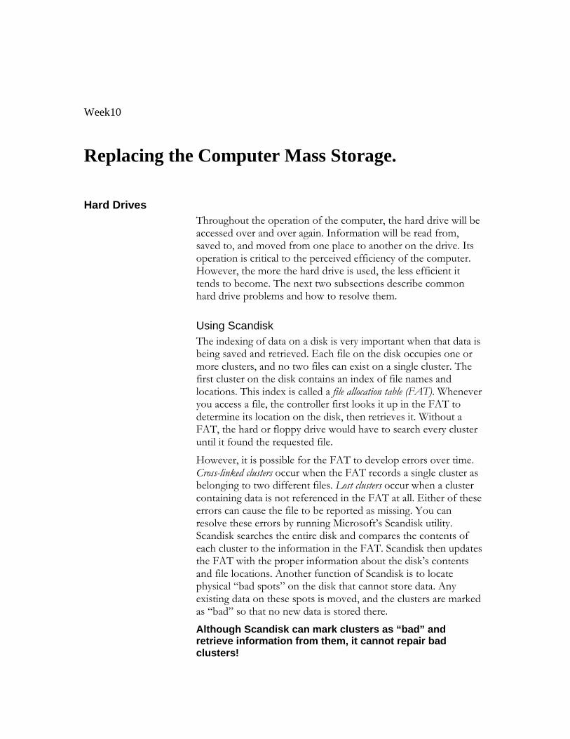
Hard disk
Mechanics
A hard disk uses rigid rotating platters (disks). It stores and retrieves digital data from a planar magnetic surface. Information is written to the disk by transmitting an electromagnetic flux through an antenna or write head that is very close to a magnetic material, which in turn changes its polarization due to the flux. The information can be read back in a reverse manner, as the magnetic fields cause electrical change in the coil or read head that passes over it
A typical hard disk drive design consists of a central axis or spindle upon which the platters spin at a constant speed. Moving along and between the platters on a common armature are the read-write heads, with one head for each platter face. The armature moves the heads radially across the platters as they spin, allowing each head access to the entirety of the platter.
The associated electronics control the movement of the read-write armature and the rotation of the disk, and perform reads and writes on demand from the disk controller. Modern drive electronics are capable of scheduling reads and writes efficiently across the disk and remapping sectors of the disk which have failed.
Also, most major hard drive and motherboard vendors now support S.M.A.R.T. technology, by which impending failures can often be predicted, allowing the user to be alerted in time to prevent data loss.
The (mostly) sealed enclosure protects the drive internals from dust, condensation, and other sources of contamination. The hard disk's read-write heads fly on an air bearing (a cushion of air) only nanometers above the disk surface. The disk surface and the drive's internal environment must therefore be kept immaculately clean to prevent damage from fingerprints, hair, dust, smoke particles, etc. given the submicroscopic gap between the heads and disk.
Some people believe a disk drive contains a vacuum — this is incorrect, as the system relies on air pressure inside the drive to support the heads at their proper flying height while the disk is in motion. Another common misconception is that a hard drive is totally sealed. A hard disk drive requires a certain range of air pressures in order to operate properly. If the air pressure is too low, the air will not exert enough force on the flying head, the head will not be at the proper height, and there is a risk of head crashes and data loss. (Specially manufactured sealed and pressurized drives are needed for reliable high-altitude operation, above about 10,000 feet. This does not apply to pressurized enclosures, like an airplane cabin.) Modern drives include temperature sensors and adjust their operation to the operating environment.
The inside of a hard disk with the platter removed. To the left is the read-write arm. In the middle the electromagnets of the platter's motor can be seen.
Hard disk drives are not airtight. They have a permeable filter (a breather filter ) between the top cover and inside of the drive, to allow the pressure inside and outside the drive to equalize while keeping out dust and dirt. The filter also allows moisture in the air to enter the drive. Very high humidity year-round will cause accelerated wear of the drive's heads (by increasing stiction, or the tendency for the heads to stick to the disk surface, which causes physical damage to the disk and spindle motor). You can see these breather holes on all drives -- they usually have a warning sticker next to them, informing the user not to cover the holes. The air inside the operating drive is constantly moving too, being swept in motion by friction with the spinning disk platters. This air passes through an internal filter to remove any leftover contaminants from manufacture, any particles that may have somehow entered the drive, and any particles generated by head crash.
Due to the extremely close spacing of the heads and disk surface, any contamination of the read-write heads or disk platters can lead to a head crash — a failure of the disk in which the head scrapes across the platter surface, often grinding away the thin magnetic
film. For GMR heads in particular, a minor head crash from contamination (that does not remove the magnetic surface of the disk) will still result in the head temporarily overheating, due to friction with the disk surface, and renders the disk unreadable until the head temperature stabilizes. Head crashes can be caused by electronic failure, a sudden power failure, physical shock, wear and tear, or poorly manufactured disks. Normally, when powering down, a hard disk moves its heads to a safe area of the disk, where no data is ever kept (the landing zone). However, especially in old models, sudden power interruptions or a power supply failure can result in the drive shutting down with the heads in the data zone, which increases the risk of data loss. Newer drives are designed such that the rotational inertia in the platters is used to safely park the heads in the case of unexpected power loss. IBM pioneered drives with "head unloading" technology that lifts the heads off the platters onto "ramps" instead of having them rest on the platters, reducing the risk of stiction. Other manufacturers also use this technology.
Spring tension from the head mounting constantly pushes the heads towards the disk. While the disk is spinning, the heads are supported by an air bearing and experience no physical contact wear. The sliders (the part of the heads that are closest to the disk and contain the pickup coil itself) are designed to reliably survive a number of landings and takeoffs from the disk surface, though wear and tear on these microscopic components eventually takes its toll. Most manufacturers design the sliders to survive 50,000 contact cycles before the chance of damage on startup rises above 50%. However, the decay rate is not linear — when a drive is younger and has fewer start/stop cycles, it has a better chance of surviving the next startup than an older, higher-mileage drive (as the head literally drags along the drive's surface until the air bearing is established). For example, the Maxtor DiamondMax series of desktop hard drives are rated to 50,000 start-stop cycles. This means that no failures attributed to the head-disk interface were seen before at least 50,000 start-stop cycles during testing.
Using rigid platters and sealing the unit allows much tighter tolerances than in a floppy disk. Consequently, hard disks can store much more data than floppy disk, and access and transmit it faster. In 2005, a typical workstation hard disk might store between 80 GB and 400 GB of data, rotate at 7,200 to 10,000 rpm, and have a sequential transfer rate of over 50 MB/s. The fastest workstation hard drives spin at 15,000 rpm. Notebook hard drives, which are physically smaller than their desktop counterparts, tend to be slower and have less capacity. Most spin at only 4,200 rpm or 5,400 rpm, though the newest top models spin at 7,200 rpm.
Access and interfaces
A hard disk is generally accessed over one of a number of bus types, including ATA (IDE, EIDE), SCSI, FireWire/IEEE 1394, USB, and Fibre Channel. In late 2002 Serial ATA was introduced.
Back in the days of the ST-506 interface, the data encoding scheme was also important. The first ST-506 disks used Modified Frequency Modulation (MFM) encoding (which is still used on the common "1.44 MB" (1.4 MiB) 3.5-inch floppy), and ran at a data rate of
5 megabits per second. Later on, controllers using 2,7 RLL (or just "RLL") encoding increased this by half, to 7.5 megabits per second; it also increased drive capacity by half.
Many ST-506 interface drives were only certified by the manufacturer to run at the lower MFM data rate, while other models (usually more expensive versions of the same basic drive) were certified to run at the higher RLL data rate. In some cases, the drive was overengineered just enough to allow the MFM-certified model to run at the faster data rate; however, this was often unreliable and was not recommended. (An RLL-certified drive could run on a MFM controller, but with 1/3 less data capacity and speed.)
ESDI also supported multiple data rates (ESDI drives always used 2,7 RLL, but at 10, 15 or 20 megabits per second), but this was usually negotiated automatically by the drive and controller; most of the time, however, 15 or 20 megabit ESDI drives weren't downward compatible (i.e. a 15 or 20 megabit drive wouldn't run on a 10 megabit controller). ESDI drives typically also had jumpers to set the number of sectors per track and (in some cases) sector size.
SCSI originally had just one speed, 5 MHz (for a maximum data rate of 5 megabytes per second), but later this was increased dramatically. The SCSI bus speed had no bearing on the drive's internal speed because of buffering between the SCSI bus and the drive's internal data bus; however, many early drives had very small buffers, and thus had to be reformatted to a different interleave (just like ST-506 drives) when used on slow computers, such as early IBM PC compatibles and Apple Macintoshes.
ATA drives have typically had no problems with interleave or data rate, due to their controller design, but many early models were incompatible with each other and couldn't run in a master/slave setup (two drives on the same cable). This was mostly remedied by the mid-1990s, when ATA's specfication was standardised and the details begun to be cleaned up, but still causes problems occasionally (especially with CD-ROM and DVD-ROM drives, and when mixing Ultra DMA and non-UDMA devices).
Serial ATA does away with master/slave setups entirely, placing each drive on its own channel (with its own set of I/O ports) instead.
FireWire/IEEE 1394 and USB(1.0/2.0) hard disks are external units containing generally ATA or SCSI drives with ports on the back allowing very simple and effective expansion and mobility. Most FireWire/IEEE 1394 models are able to daisy-chain in order to continue adding peripherals without requiring additional ports on the computer itself.
Other characteristics
Capacity (measured in gigabytes)
Physical size (inches)
Almost all hard disks today are of either the 3.5", used in desktops, or 2.5", used in laptops, variety. 2.5" drives are usually slower and have less capacity but use less power and are more tolerant of movement. Additionally, there is the CF form factor microdrive which is usually used as storage for portable devices such as mp3 players and digital cameras. The size designations can be slightly confusing, for example a 3.5" disk drive has a case that is 4" wide.
Reliability: Mean Time Between Failures (MTBF)
SATA 1.0 drives support speeds up to 10,000 rpm and mean time between failure (MTBF) levels up to 1 million hours under an eight-hour, low-duty cycle. Fibre Channel (FC) drives support up to 15,000 rpm and an MTBF of 1.4 million hours under a 24-hour duty cycle.
Number of I/O operations per second
Modern disks can perform around 50 random or 100 sequential OPS
Power consumption (especially important in battery-powered laptops)
audible noise (in dBA)
G-shock rating (surprisingly high in modern drives)
Addressing modes
There are two modes of addressing the data blocks on more recent hard disks. The older mode is CHS addressing (Cylinder-Head-Sector), used on old ST-506 and ATA drives and internally by the PC BIOS. The more recent mode is the LBA (Logical Block Addressing), used by SCSI drives and newer ATA drives (ATA drives power up in CHS mode for historical reasons).
CHS describes the disk space in terms of its physical dimensions, data-wise; this is the traditional way of accessing a disk on IBM PC compatible hardware, and while it works well for floppies (for which it was originally designed) and small hard disks, it caused problems when disks started to exceed the design limits of the PC's CHS implementation. The traditional CHS limit was 1024 cylinders, 16 heads and 63 sectors; on a drive with 512-byte sectors, this comes to 504 MiB (528 megabytes). The origin of the CHS limit lies in a combination of the limitations of IBM's BIOS interface (which allowed 1024 cylinders, 256 heads and 64 sectors; sectors were counted from 1, reducing that number to 63, giving an addressing limit of 8064 MiB or 7.8 GiB), and a hardware limitation of the AT's hard disk controller (which allowed up to 65536 cylinders and 256 sectors, but only 16 heads, putting its addressing limit at 2^28 bits or 128 GiB).
When drives larger than 504 MiB began to appear in the mid-1990s, many system BIOSes had problems communicating with them, requiring LBA BIOS upgrades or
special driver software to work correctly. Even after the introduction of LBA, similar limitations reappeared several times over the following years: at 2.1, 4.2, 8.4, 32, and 128 GiB. The 2.1, 4.2 and 32 GiB limits are hard limits: fitting a drive larger than the limit results in a PC that refuses to boot, unless the drive includes special jumpers to make it appear as a smaller capacity. The 8.4 and 128 GiB limits are soft limits: the PC simply ignores the extra capacity and reports a drive of the maximum size it is able to communicate with.
SCSI drives, however, have always used LBA addressing, which describes the disk as a linear, sequentially-numbered set of blocks. SCSI mode page commands can be used to get the physical specifications of the disk, but this is not used to read or write data; this is an artifact of the early days of SCSI, circa 1986, when a disk attached to a SCSI bus could just as well be an ST-506 or ESDI drive attached through a bridge (and therefore having a CHS configuration that was subject to change) as it could be a native SCSI device. Because PCs use CHS addressing internally, the BIOS code on PC SCSI host adapters does CHS-to-LBA translation, and provides a set of CHS drive parameters that tries to match the total number of LBA blocks as closely as possible.
ATA drives can either use their native CHS parameters (only on very early drives; hard drives made since the early 1990s use zone bit recording, and thus don't have a set number of sectors per track), use a "translated" CHS profile (similar to what SCSI host adapters provide), or run in ATA LBA mode, as specified by ATA-2. To maintain some degree of compatibility with older computers, LBA mode generally has to be requested explicitly by the host computer. ATA drives larger than 8 GiB are always accessed by LBA, due to the 8 GiB limit described above.
See also: hard disk drive partitioning, master boot record, file system, drive letter assignment, boot sector.
Manufacturers
Hitachi 2.5 inch laptop hard drive
Most of the world's hard disks are now manufactured by just a handful of large firms: Seagate, Maxtor, Western Digital, Samsung, and the former drive manufacturing division of IBM, now sold to Hitachi. Fujitsu continues to make specialist notebook and SCSI drives but exited the mass market in 2001. Toshiba is a major manufacturer of 2.5-inch and 1.8-inch notebook drives.
Firms that have come and gone
Dozens of former hard drive manufacturers have gone out of business, merged, or closed their hard drive divisions; as capacities and demand for products increased, profits became hard to find, and there were shakeouts in the late 1980s and late 1990s. The first notable casualty of the business in the PC era was Computer Memories International or CMI; after the 1985 incident with the faulty 20MB AT drives, CMI's reputation never recovered, and they exited the hard drive business in 1987. Another notable failure was MiniScribe, who went bankrupt in 1990 after it was found that they had "cooked the books" and inflated sales numbers for several years. Many other smaller companies (like Kalok, Microscience, LaPine, Areal, Priam and PrairieTek) also did not survive the shakeout, and had disappeared by 1993; Micropolis was able to hold on until 1997, and JTS, a relative latecomer to the scene, lasted only a few years and was gone by 1999. Rodime was also an important manufacturer during the 1980s, but stopped making drives in the early 1990s amid the shakeout and now concentrates on technology licensing; they hold a number of patents related to 3.5-inch form factor hard drives.
There have also been a number of notable mergers in the hard disk industry:
Tandon sold its disk manufacturing division to Western Digital (which was then a controller maker and ASIC house) in 1988; by the early 1990s Western Digital disks were among the top sellers.
Quantum bought DEC's storage division in 1994, and later (2000) sold the hard disk division to Maxtor to concentrate on tape drives.
In 1995, Conner Peripherals announced a merger with Seagate (who had earlier bought Imprimis from CDC), which completed in early 1996.
JTS infamously merged with Atari in 1996, giving it the capital it needed to bring its drive range into production.
In 2003, following the controversy over the mass failures of the Deskstar 75GXP range (which resulted in lost sales of its follow-ons), hard disk pioneer IBM sold the majority of its disk division to Hitachi, who renamed it Hitachi Global Storage Technologies.
"Marketing" capacity versus true capacity
It is important to note that hard drive manufacturers often use the metric definition of the prefixes "giga" and "mega." However, nearly all operating system utilities report capacities using binary definitions for the prefixes. This is largely historical, since when storage capacities started to exceed thousands of bytes, there were no standard binary prefixes (the IEC only standardized binary prefixes in 1999), so 210 (1024) bytes was called a kilobyte because 1024 is "close enough" to the metric prefix kilo, which is defined as 103 or 1000. This trend became habit and continued to be applied to the prefixes "mega," "giga," and even "tera." Obviously the discrepancy becomes much more noticeable in reported capacities in the multiple gigabyte range, and users will often notice that the volume capacity reported by their OS is significantly less than that
advertised by the hard drive manufacturer. For example, a drive advertised as 200 GB can be expected to store close to 200 x 109, or 200 billion, bytes. This uses the proper SI definition of "giga," 109 and cannot be considered as incorrect. Since utilities provided by the operating system probably define a Gigabyte as 230, or 1073741824, bytes, the reported capacity of the drive will be closer to 186.26 GB (actually, GiB), a difference of well over ten gigabytes. For this very reason, many utilities that report capacity have begun to use the aforementioned IEC standard binary prefixes (e.g. KiB, MiB, GiB) since their definitions are not ambiguous.
Another side point is that many people mistakenly attribute the discrepancy in reported and advertised capacities to reserved space used for file system and partition accounting information. However, for large (several GiB) filesystems, this data rarely occupies more than several MiB, and therefore cannot possibly account for the apparent "loss" of tens of Gigabytes.
Hard disk usage
From the original use of a hard drive in a single computer, techniques for guarding against hard disk failure were developed such as the redundant array of independent disks (RAID). Hard disks are also found in network attached storage (NAS) devices, but for large volumes of data are most efficiently used in a storage area network (SAN). Applications for hard disk drives expanded to include personal video recorders, digital audio players, digital organizers and digital cameras. In 2005 the first cellular telephones to include hard disk drives were introduced by Samsung and Nokia.
History
The first computer with a hard disk drive as standard was the IBM 350 Disk File, introduced in 1955 with the IBM 305 computer. This drive had fifty 24 inch platters, with a total capacity of five million characters. In 1952, an IBM engineer named Reynold Johnson developed a massive hard disk consisting of fifty platters, each two feet wide, that rotated on a spindle at 1200 rpm with read/write heads for the first database running RCAs Bismark computer.
In 1973, IBM introduced the 3340 "Winchester" disk system (the 30MB + 30 millisecond access time led the project to be named after the Winchester 30-30 rifle), the first to use a sealed head/disk assembly (HDA). Almost all modern disk drives now use this technology, and the term "Winchester" became a common description for all hard disks, though generally falling out of use during the 1990s.
For many years, hard disks were large, cumbersome devices, more suited to use in the protected environment of a data center or large office than in a harsh industrial environment (due to their delicacy), or small office or home (due to their size and power consumption). Before the early 1980s, most hard disks had 8-inch or 14-inch platters, required an equipment rack or a large amount of floor space (especially the large
removable-media drives, which were often referred to as "washing machines"), and in many cases needed special power hookups for the large motors they used. Because of this, hard disks were not commonly used with microcomputers until after 1980, when Seagate Technology introduced the ST-506, the first 5.25-inch hard drive, with a capacity of 5 megabytes. In fact, in its factory configuration the original IBM PC (IBM 5150) was not equipped with a hard drive.
Most microcomputer hard disk drives in the early 1980s were not sold under their manufacturer's names, but by OEMs as part of larger peripherals (such as the Corvus Disk System and the Apple ProFile). The IBM PC/XT had an internal hard disk, however, and this started a trend toward buying "bare" drives (often by mail order) and installing them directly into a system. Hard disk makers started marketing to end users as well as OEMs, and by the mid-1990s, hard disks had become available on retail store shelves.
While internal drives became the system of choice on PCs, external hard drives remained popular for much longer on the Apple Macintosh and other platforms. Every Mac made between 1986 and 1998 has a SCSI port on the back, making external expansion easy; also, "toaster" Macs did not have easily accessible hard drive bays (or, in the case of the Mac Plus, any hard drive bay at all), so on those models, external SCSI disks were the only reasonable option. External SCSI drives were also popular with older microcomputers such as the Apple II series and the Commodore 64, and were also used extensively in servers, a usage which is still popular today. The appearance in the late 1990s of high-speed external interfaces such as USB and IEEE 1394 (FireWire) has made external disk systems popular among regular users once again, especially for users that move large amounts of data between two or more locations, and most hard disk makers now make their disks available in external cases.
The capacity of hard drives has grown exponentially over time. With early personal computers, a drive with a 20 megabyte capacity was considered large. In the latter half of the 1990s, hard drives with capacities of 1 gigabyte and greater became available. As of early 2005, the "smallest" desktop hard disk in production has a capacity of 40 gigabytes, while the largest-capacity internal drives are a half terabyte (500 gigabytes), with external drives at or exceeding one terabyte. As far as PC history is concerned, the major drive families have been MFM, RLL, ESDI, SCSI, IDE and EIDE, and now SATA. MFM drives required that the electronics on the "controller" be compatible with the electronics on the card — disks and controllers had to be compatible. RLL (Run Length Limited) was a way of encoding bits onto the platters that allowed for better density. Most RLL drives also needed to be "compatible" with the controllers that communicated with them. ESDI was an interface developed by Maxtor. It allowed for faster communication between the PC and the disk. SCSI (originally named SASI for Shugart (sic) Associates) or Small Computer System Interface was an early competitor with ESDI. When the price of electronics dropped (and because of a demand by consumers) the electronics that had been stored on the controller card was moved to the disk drive itself. This advance was known as "Integrated Drive Electronics" or IDE. Eventually, IDE manufacturers wanted the speed of IDE to approach the speed of SCSI drives. IDE drives were slower because
they did not have as big a cache as the SCSI drives, and they could not write directly to RAM. IDE manufacturers attempted to close this speed gap by introducing Logical Block Addressing (LBA). These drives were known as EIDE. While EIDE was introduced, though, SCSI manufacturers continued to improve SCSI's performance. The increase in SCSI performance came at a price — its interfaces were more expensive. In order for EIDE's performance to increase (while keeping the cost of the associated electronics low), it was realized that the only way to do this was to move from "parallel" interfaces to "serial" interfaces, the result of which is the SATA interface. However, as of 2005, performance of SATA and PATA disks is comparable. Fibre channel (FC) interfaces are left to discussions of server drives.
Week10
Replacing the Computer Mass Storage. Hard Drives Throughout the operation of the computer, the hard drive will be
accessed over and over again. Information will be read from, saved to, and moved from one place to another on the drive. Its operation is critical to the perceived efficiency of the computer. However, the more the hard drive is used, the less efficient it tends to become. The next two subsections describe common hard drive problems and how to resolve them.
Using Scandisk
The indexing of data on a disk is very important when that data is being saved and retrieved. Each file on the disk occupies one or more clusters, and no two files can exist on a single cluster. The first cluster on the disk contains an index of file names and locations. This index is called a file allocation table (FAT). Whenever you access a file, the controller first looks it up in the FAT to determine its location on the disk, then retrieves it. Without a FAT, the hard or floppy drive would have to search every cluster until it found the requested file.
However, it is possible for the FAT to develop errors over time. Cross-linked clusters occur when the FAT records a single cluster as belonging to two different files. Lost clusters occur when a cluster containing data is not referenced in the FAT at all. Either of these errors can cause the file to be reported as missing. You can resolve these errors by running Microsoft’s Scandisk utility. Scandisk searches the entire disk and compares the contents of each cluster to the information in the FAT. Scandisk then updates the FAT with the proper information about the disk’s contents and file locations. Another function of Scandisk is to locate physical “bad spots” on the disk that cannot store data. Any existing data on these spots is moved, and the clusters are marked as “bad” so that no new data is stored there.
Although Scandisk can mark clusters as “bad” and retrieve information from them, it cannot repair bad clusters!
Defragmenting the Hard Drive
When files are saved to the hard or floppy drive, they are written to the first available cluster(s). Ideally, subsequent files are all saved in consecutive clusters on the disk. However, suppose a file resided on cluster 4, and another file resided on clusters 5–8. If you increased the size of the first file so that it no longer fit on one cluster, it would occupy clusters 4 and 9. Next, suppose you deleted the file on clusters 5–8 and replaced it with a larger file. That file would now reside on clusters 5–8 and perhaps 10 and 11. These files no longer reside on consecutive clusters and are said to be fragmented. Fragmentation can cause the hard or floppy drive to retrieve files more slowly, and can actually cause undue wear and tear on the drive’s read/write heads.
To defragment a hard or floppy disk, you can run Microsoft’s Disk Defragmenter in Windows 9x. This utility rewrites the data on the disk so that files are placed on contiguous clusters. Follow the steps in Exercise 2-5 to defragment a hard drive.
EXERCISE 2-5: Defragmenting a Hard Drive 1. Exit all running applications and disable the screen
saver. 2. From the Start menu, select Programs | Accessories |
System Tools | Disk Defragmenter. 3. You will be presented with a Select Drive dialog box.
Select the appropriate hard drive from the drop-down menu, then click OK.
4. The Defragmenter utility will begin. You can view the cluster-by-cluster details of the operation by clicking the Show Details button.
5. When the process is complete, you will be informed via a dialog box, the contents of which will vary, depending on the OS you are using. Choose to either exit the utility or defragment another disk.
Using your knowledge of hard drive utilities, answer the following Scenario & Solution questions.
SCENARIO & SOLUTION
The computer reported a corruption error when I tried to access the floppy disk. What should I do?
Run Scandisk.
How can I speed up my hard drive? Run Disk Defragmenter.
My computer reports that a particular file doesn’t exist, but I know I saved it. What happened, and how can I find that file?
It is possible that the file exists but is not indexed properly. Run Scandisk. If the file exists, the FAT will be updated and you will be able to access it.
� Week11 � Objective(s):
� How to replace computer Video Display Unit
Visual Display Unit (VDU) WEEK 9
VDU is a device, such as a television screen, which produces a visible display of data. The VDU is also called Monitor.
The computer monitor is an output device that is part of the computer's display system. A cable connects the monitor to a video adapter (video card) that is installed in an expansion slot on the computer’s motherboard. This system converts signals into text and pictures and displays them on a TV-like screen (the monitor).
The computer sends a signal to the video adapter, telling it what character, image or graphic to display. The video adapter converts that signal to a set of instructions that tell the display device (monitor) how to draw the image on the screen.
Types of Monitors
There are many ways to classify monitors. The most basic is in terms of color capabilities, which separates monitors into three classes:
• Monochrome : Monochrome monitors actually display two colors, one for the background and one for the foreground. The colors can be black and white, green and black, or amber and black. • Gray-scale : A gray-scale monitor is a special type of monochrome monitor capable of displaying different shades of gray. • Colour: Colour monitors can display anywhere from 16 to over 1 million different colors. Color monitors are sometimes called RGB monitors because they accept three separate signals -- red, green, and blue.
There are mainly two types of monitors in use. They are:
1. CRT monitor 2. LCD Monitor
1. CRT Monitor
Working Principle
A CRT is a vacuumed sealed tube with no air inside. In a CRT monitor, the electron gun produces a beam of electrons that travels through a focusing system, deflection coils, and then into the screen to display a picture. The rest of this website is dedicated to explaining the details of the system.
The above figure is the inside of a Cathode-ray tube. A beam of electrons (cathode rays) is emitted by the electron gun, passes through various focusing and deflection systems, and then hits specific areas on a phosphor-coated screen.
Electron Gun
The electron gun consists of a metal cathode, control grid, and various anodes as labeled above in the figure. It is important to remember that electrons are small negatively particles, because their direction is controlled by the type of voltage. Negative charges repel each other, and opposites attract.
• First, heat is generated by an electric current passing through a
heating filament, and it causes electrons to fly off the cathode.
• Intensity of the electron beam is controlled by the voltage at the
control grid. A high negative voltage in the control grid with stop the
electron beam.
• Next, inside the vacuum of the CRT, the focusing anode concentrates
the electrons into a small beam so they can be accelerated.
• Finally, the negatively charged electrons are accelerated towards the
screen by a high positive voltage at the accelerating anode.
Focusing System
After the electron beam leaves the electron gun, the electrons go through another focusing system. The focusing system, a metal cylinder, uses a positive electric field that causes the electrons to converge into a small point. This assures that the electron beam will only hit one spot on the monitor at a time. Improving the focusing system increases the sharpness of the picture on the screen.
Deflection Coils
The magnetic deflection coils are used to hit the correct part of the screen. They are mounted on all sides of the cathode-ray tube, and they control the horizontal and vertical direction of the electron beam. Varying the electricity running through the coils aims the beam at the proper screen location.
The Phosphor Coating
The light on the screen that a user sees is caused by electrons illuminating a phosphor coating. Part of the energy from the electrons is converted to heat by friction, and the rest of the energy causes the phosphor to become “excited.” The phosphor does not hold its excited state for long, and the light quickly dwindles. Different phosphors hold the light for different amounts of time. The amount of time it takes for the phosphor to lose 9/10ths of its original intensity is called the persistence.
Color
A CRT monitor displays color by using the phosphor and the shadow-mask method. This is the same system that televisions use. It is based on the RGB model, which means there is a red, green, and blue dot at each position on the screen. Three electron guns are used to activate each color separately. Varying the intensity of each electron gun, or shutting the beams off, determines the color. This is shown in the figure below. If all beams are off, then the dot is black. If all beams are on, then the color of the dot is white. Today, the average monitor has the capability to display millions of different colors.
Raster Scanning
Since the phosphor dots lose their color and light very quickly, a system must be incorporated to refresh, or redraw, the picture at a high rate. The picture is refreshed by raster-scanning, which is based off television technology. The electron beams are swept along each row activating each spot on the screen to display the proper colors. As you can see in the figure below, it activates each spot from top to bottom as well. Each of these spots is called a pixel. Increasing the refresh rate, number of pixels, and colors creates a better quality picture on the screen.
The Color CRT Monitor
A CRT monitor is a system with many parts and methods, working in perfect unison. The process starts with electrons being emitted by the electron gun. They are pushed into the cathode-ray tube, and then the electrons light up phosphor pixels on the screen. So every picture that a computer user sees is not solid at all; it is actually made up of tiny individual pixels constantly be refreshed. This entire cycle is controlled behind the scenes by a complex video card and computer,
2. LCD Monitor (Liquid Crystal Display)
A Liquid crystal display or LCD is a digital display technology that produces images on a flat surface by shining light through liquid crystals and colored filters.
• Takes up less space, consumes less power, and produces less heat than traditional cathode-ray tube monitors.
• Lack of flicker and low glare reduce eyestrain. • Much more expensive than CRTs of comparable size.
Working principle
liquid crystals are liquid chemicals whose molecules can be aligned precisely when subjected to electrical fields--much in the way metal shavings line up in the field of a magnet. When properly aligned, the liquid crystals allow light to pass through.
Whether on a laptop or a desktop, an LCD screen is a multilayered, sideways sandwich. A fluorescent light source, known as the backlight, makes up the rearmost slice of bread. This light passes through the first of two polarizing filters. The polarized light then passes through a layer that contains thousands of liquid crystal blobs arrayed in tiny containers called cells. The cells are, in turn, arrayed in rows across the screen; one or more cells make up one pixel (the smallest discernible dot on a display). Electric leads around the edge of the LCD create an electric field that twists the crystal molecule, which lines the light up with the second polarizing filter and allows it to pass through. Figure below shows the constructional details of an LCD panel.
For a simple monochrome LCD, such as you'd find on a PalmPilot, that's it: The protective cover goes on, and it's finished. But color LCDs, such as you'd find on a laptop PC, are more complex.
In a color LCD panel, each pixel is made up of three liquid crystal cells. Each of those three cells is fronted by a red, green, or blue filter. Light passing through the filtered cells creates the colors you see on the LCD. Occasionally the mechanism that sends the electrical current to one or more pixels fails; in those instances you'll see a completely dark, "bad" pixel.
Graphics Accelerator Cards
Early graphics adapters received data from the processor and basically forwarded the signals to the monitor, leaving the CPU to do all the work related to processing and calculating. In non-accelerated graphics adapters, the computer needed to change each pixel individually to change the image on the screen. After graphical user interfaces (like Windows for example) became popular, systems began to slow down as the CPU was left trying to move large amounts of data from the system RAM to the video card.
Today all new video cards are accelerated and are connected to the system's CPU through high-speed buses such as PCI or AGP.
Also known as a 3D accelerator, the graphics accelerator card is an internal board that generally is installed into the PCI or AGP slot and reduces the time it takes to produce images on the computer screen by incorporating its own processor and memory.
The biggest difference between accelerated and non-accelerated cards is that with accelerated video cards, the CPU no longer has to carry the bulk of the processing burden from graphics calculations. Since the video card has its own processor, it is able to perform most of the work, leaving your CPU free to process other tasks.
Synchronous Graphics RAM (SGRAM)
SGRAM is a type of video adapter that contains its own processor to boost performance levels. These processors are specialized for computing graphical transformations, so they achieve better results than the general-purpose CPU used by the computer. In addition, they free up the computer's CPU to execute other commands while the graphics accelerator is handling graphics computations. The popularity of graphical applications, and especially multimedia applications and computer games, has made graphics accelerators not only a common enhancement, but a necessity.
The popularity of graphical applications, and especially multimedia applications, has made graphics accelerators not only a common enhancement, but a necessity. Most computer manufacturers now bundle a graphics accelerator with their mid-range and high-end systems.
Monitor The function of a monitor is to produce visual responses to user requests. Most desktop computers use cathode ray tube (CRT) monitors. CRTs use an electron gun to activate phosphors behind the screen. Each dot on the monitor, called a pixel, has the ability to generate red, green, or blue, depending on the signals it receives. This combination of colors results in the total display you see on the monitor.
Monitors are available in a wide array of colors and resolutions. The word resolution refers to the size and number of pixels that a monitor can display. Higher resolutions display more pixels and have better visual output. Lower resolutions result in grainy displays.
Color graphics adapter (CGA) monitors are an older type and can display combinations of red, green, and blue at different intensities, resulting in 16 different colors. The maximum resolution of a CGA monitor is 640 x 200 pixels in monochrome mode and 160 x 100 pixels in 16-color mode.
Enhanced graphics adapter (EGA) monitors are capable of generating up to 64 colors, of which 16 can be displayed at any one time. EGA monitors have a maximum resolution of 720 x 350 when displaying text only and 640 x 350 in graphics mode.
Virtual graphics array (VGA) monitors were the first to use analog rather than digital output. Instead of creating displays based on the absence or presence of a color (as in digital CGA and EGA monitors), VGA monitors can display a wide range of colors and intensities. They can produce around 16 million different colors but can display only up to 256 different colors at a time. This color setting is often called 16-bit high color. VGA monitors have a maximum resolution of 720 x 400 in text mode and 640 x 480 in graphics mode.
Super VGA (SVGA) monitors introduce yet another improvement: They also use analog input and can provide resolutions as high as 1280 x 1024. Some SVGA monitors can provide even higher resolutions. SVGA monitors can display up to 16 million colors at once, referred to as 32-bit true color. Because the human eye can distinguish only approximately 10 million different colors, it is likely that monitor technology will focus on improving resolution only.
All monitors receive their signals from video cards attached to the motherboard. The monitor technology must match the technology of the video card to which it is attached. That is, an EGA monitor will work only with an EGA video card, and an SVGA monitor must be attached to an SVGA video card. Table 1-1 presents a summary of monitor types and characteristics.
Monitor Total Number of
Number of Colors That Can
Maximum Resolution
Input
Colors Be Simultaneously Displayed
CGA 16 16 Monochrome: 640 x 200 Color: 160 x 100
Digital
EGA 64 16 Text mode: 720 x 350 Graphics mode: 640 x 350
Digital
VGA More than 16 million
256 Text mode: 720 x 400 Graphics mode: 640x480
Analog
SVGA More than 16 million
More than 16 million
1280 x 1024 Analog
Table Error! Bookmark not defined.: Monitor Types and Their Characteristics
Computer Display (Monitor)
A computer display, monitor or screen is a computer peripheral device capable of showing still or moving images generated by a computer and processed by a graphics card. Monitors generally conform to one or more display standards. Sometimes the name "display" is preferred to the word "monitor", as the latter can be ambiguous alongside the other senses of "monitor" meaning "machine-level debugger" or "thread synchronization mechanism". Computer displays are sometimes called heads, especially when talking about how many are connected to a computer. Once an essential component of a computer terminal, computer displays have long since become standardized peripherals in their own right.
CRT A modern CRT display has considerable flexibility: it can often handle all resolutions
from 640 by 480 pixels (640×480) up to 2048 by 1536 pixels (2048×1536) with 32-bit colour and a variety of refresh rates.
LCD
A liquid crystal display (LCD) is a thin, flat display device made up of any number of color or monochrome pixels arrayed in front of a light source or reflector. It is prized by engineers because it uses very small amounts of electric power, and is therefore suitable for use in battery-powered electronic devices.
Replacing the Computer Display Unit:
One of the most important item one has to care about regarding his personal computer is his display unit.
To decide to replace a display unit is not a simple decision. The following are some guidelines to tell you if you need to replace your display unit or not:
1- The size of monitor you have and the size of the newer one. Sometimes you have
a 15” Cathode-Ray-Tube (CRT) monitor. You may replace it with a 17” or 19 “ one. A bigger monitor is better for your sight.
2- The type of monitor. Some brand names are better than others. The difference in requirements can be studied by the sheets with each. One of the most important thing about a display unit is its resolution. It is measured in pixels. The more the resolution of a display unit, the better it will be. Also there is another factor which is the dot pitch and it is measured in mm’s. The lower the dot pitch, the better the display unit.
3- Sometimes one may think of replacing a CRT monitor with an LCD one. LCD monitors are better for the person who sits a lot in front of a computer. It costs more but you feel better when using it instead of a CRT monitor.
Replacing the monitor is very simple. You just turn off the power, pull out the power cordage and then put the newer monitor in its place.
� Week12 How to replace computer Add On Cards � � Objective(s): � How to replace computer Add On Cards � � Input/output
Input/output , or I/O, is the collection of interfaces that different functional units (sub-systems) of an information processing system use to communicate with each other, or to the signals (information) sent through those interfaces. Inputs are the signals received by the unit, and outputs are the signals sent from it. The term can also be used as part of an action; to "do I/O" is to perform an input or output operation. I/O devices are used by a person (or other system) to communicate with a computer. For instance, keyboards and mice are considered input devices (from a human perspective) and monitors and printers are considered output devices (again, from a human perspective).
It is important to notice that the previous designations of these devices as either input or output change when the perspective changes. Mice and keyboards take physical movement from the human user as input and convert it into signals that a computer can understand as output. The output from these devices is treated as input by the computer. Similarly, printers and monitors take signals that a computer outputs as input. They then convert these signals into output representations that human users can see or read. (For a human user the process of reading or seeing these representations is input.)
Strictly speaking, however, the combination of the CPU and main memory (i.e. memory that the CPU can read and write to directly, with individual instructions) is considered the heart of a computer, and any movement of information from or to that complex, for example to or from a disk drive, is also considered I/O
Replacing the Add-On Cards:
Sometimes we need to get better performance of our PC regarding video’s or audio’s. If this is the case then it’s time to replace your VGA card or sound card.
The following picture (Figure 12) shows an AGP slot where we assemble a VGA card and 6 PCI slots where we assemble sound cards, modems and other add-on cards.
Figure 12:AGP slot and six PCI slots on a motherboard
Replacing a VGA card:
One may need to replace a video card if it fails or if he/she wants a newer one with better specifications. The VGA card is very important in many software applications like video-editing, animations, CAD, or else. When you decide to replace your old VGA card you must know in advance that the newer one will meet your requirements and has compatibility with the motherboard. The following are the steps of replacing a VGA card.
Video cards are pretty reliable, though some of the newer ones run so hot that they have their own cooling systems, and if the fan fails, the video processor can't be too far behind. Almost all systems you crack open these days will feature an AGP video card, only the oldest system have PCI video and only the very newest feature PCI Express. The first step to installing a video card is opening up the case, which varies with non-standard systems, but for a normal mid-tower, it means two screws at the most. You want to remove the side that's above the motherboard, which you can easily determine by looking at the back of the case. The I/O core at the bottom with the ports is attached to the motherboard. As soon as the lid is off, we remove the video card hold-down screw.
There are few PC jobs easier than installing the video card. Most AGP slots lack the latch that the cards were designed to accept on the back edge. That latching point is clearly visible on the old video card we're replacing, you can see the "L" shape under the four video memory chips on the right side of the card. If the motherboard had supported a lock, it would have closed over the "L." In fact, the primary failure mode for AGP video cards is when they pop partially out of the slot on their own (or because the monitor cable pulls them up), so before you assume any video card is dead, you should reseat it in the slot and give it another try.
Our replacement 3D AGP video card is shown here over the brown AGP slot.. You can see the key slot in the card edge that with a few orphan exceptions, will prevent you from installing the wrong voltage video card in the slot. Only the oldest 1X and 2X AGP video slots had any compatibility issues. The 4X cards were probably the most common, they are now being replaced by 8X AGP, but PCI Express will take over soon, so the majority of PCs in use will never feature the 8X AGP cards. You usually have to replace an AGP video card with the same speed since the existing card will be the fastest the motherboard could use. Handle the video card by the corners and don't touch the gold contact fingers because the oil from your skin can degrade the electrical signals.
Once you have the video card positioned properly over the AGP slot, seat it evenly by pressing down on the top edge at both the front and back of the card (left). Once it's seated, install the retaining screw on the back rail (below), then inspect the card to make sure it's still fully seated in the slot. On poorly designed motherboards or cases, installing the screw can cause the video card to pivot on the back of the slot and lose contact with the front of the slot. That pretty much covers how to replace an AGP video card, unless you count installing the software drivers as a step. Just use the CD that comes with the video card and hopefully there'll be a wizard.
WEEK13
� Objective: How to replace computer Add On Cards
Network cards have many different feature, one of the most important is the speed. So, we need to replace it if it fails or if we need a newer one with better performance.
Here are the steps for replacing a sound card.
Sound cards don't have a particularly high failure rate but they get replaced more often than any other adapter, with the possible exception of modems. The reason is that older PCI sound cards that came stock with systems offered pretty lousy performance, so gamers and musicians often find they have to replace the sound card just to work with the programs they buy. The first step is to unplug the PC and open the case.. You only need to remove the top lid on the average midtower - two screw, slide back a couple inches, and off. You can see the original sound card connectors in the center of the adapter bay.
The original sound card is secured in the case with a single screw. If you've done this before, you'll see that there's something missing along the top edge. This PC was built without an analog audio lead connecting the CD drive to the sound card, which means it never would have been able to play music CDs. This is an extremely common issue with PC's that were built without any quality control or a CD was installed at a later date by somebody who had a lazy attack. We remove the old sound card, and also a blank bay cover next to it, because our PCI 5.1 upgrade sound card needs two slots for the SPDIF riser.
Speaking of the SPDIF (Sony/Phillips Digital Interface), we now connect this daughter card, or riser, to the new sound card. This connector is keyed the top left hole on this 2x5 connector is blocked to match the missing corner pin on the board connection block. You can also see just above the forefinger the 4x1 connector where we'll later connect the CD audio lead. To the right of those connectors is the silk screen explaining which is which..
Here you can see the small SPDIF daughter board held above the basic sound card. It's a 5.1 sound card, five regular channels (front left and right, rear left and right, center) plus a low frequency or sub-woofer channel. When you're upgrading a sound card, a 5.1 is pretty much the minimum I'd consider. Newer motherboards come with 6.1 and even 7.1 sound built into the motherboard, so this isn't anything you should have to fool around with a newer PC. The game port is quickly becoming obsolete, replaced with USB game controllers, but many replacement sound cards, like this one, still feature a legacy game port.
WEEK14
Keyboard and Pointing devices WEEK 7
The Keyboard is an input device of computers. Keyboard is also the primary way to interact with a PC.
Types of Keyboards Keyboards have changed very little in layout since their introduction. In fact, the most common change has simply been the natural evolution of adding more keys that provide additional functionality.
The most common keyboards classified based on the number of keys are:
• 101-key Enhanced keyboard • 104-key Windows keyboard • 82-key Apple standard keyboard • 108-key Apple Extended keyboard
Keyboards are available in various forms. The different types of keyboards are:
1. Normal Windows compatible keyboard
2. Multimedia Keyboard
This is a keyboard which is provided with some additional or hot keys to take advanatge of the internet.
3. Ergonomic Keyboard
This is a keyboard designed to keep the hands in a natural position that helps avoid repetitive stress injuries to the wrists
4. Cordless Keyboards
These keyboards do not make use of any cord or cable connection. This communicates the data using radio frequency and is operated by a battery. The distance at which the key board can be used is around 15 feet.
5. Projection keyboards.
These are the latest types of keyboards. These are virtual keyboards that can be projected and touched on any surface. The keyboard watches your fingers move and translates
that action into keystrokes in the device.
Troubleshooting Keyboards
A good Keyboard will have to be smooth keys and working properly is a must thing. Keyboard cleaning tips is very necessary for all of us who use computers. We all get tension when any button of our Keyboard sticks and cannot work properly as we like. Mostly this happened because of dust or dirt in Keyboard. then the Keyboard need cleaning. here some of Keyboard cleaning tips are listed which is useful for all of us. this Keyboard cleaning guide will take you through cleaning a Keyboard step by step. Proper cleaning and lubrication makes the keyboard performance smooth. There are many types of computer keyboards are available in market.
Replacing a keyboard or a mouse.
Once a keyboard or a mouse has to be replaced, some issues have to be taken into consideration : First, we must look at the motherboard if supports the type of the keyboard or a mouse. For keyboards we have AT, PS2, USB and wireless types. Some old motherboards do not support USB type, so we must be careful when we choose this type of keyboard. This also applies to mice, but instead of AT we have serial mouse. The Input/Output ports that are found on the rear side of a computer motherboard are shown in figure 13
Figure 13: The Here are some figures of different
In the shown figure we can plug the keyboard in either B or C. B is the PS2 port and C is the USB port. The mouse can be plugged in A, C or D. A is the PS2, C is the USB and D is the Serial port.
When deciding to install a new mouse or keyboard you have to assure that your motherboard supports it. Sometimes we may use what is called a PS2-to-AT adaptor to connect a new ps2- keyboard to an old motherboard that only supports AT connection.
The word "modem" is a contraction of the words modulator-demodulator. A modem is typically used to send digital data over a phone line.
The sending modem modulates the data into a signal that is compatible with the phone line, and the receiving modem demodulates the signal back into digital data. Wireless modems convert digital data into radio signals and back.
Modems came into existence in the 1960s as a way to allow terminals to connect to computers over the phone lines. A typical arrangement is shown below:
Modem standards
Most modem standards are referred to by a code assigned by the Consultative Committee for International Telephony and Telegraphy (CCITT).
The standards fall into three categories:
1. Modulation (speed) 2. Error correction
3. Data compression
1. Modulation (speed) standards
Modulation (or speed) standards involve the rates and ways modems communicate with each other, and how they negotiate the best communication speed they can both use for the connection. These are common modulation standards: V.22.
The CCITT standard for data transmission at speeds up to 2400 bps.
HST
The USR proprietary standard for data transmission at speeds from 9600 to 16800 bps, depending on the model.
The reverse channel is much slower. If you are connecting to another type of modem, the best speed you can expect is 2400 bps. Hayes V-series
The Hayes proprietary standard for data transmission at speeds up to 9600 bps.
The reverse channel is much slower. If you are connecting to another type of modem, the best speed you can expect is 2400 bps. V.32
The CCITT standard for data transmission at speeds up to 9600 bps.
V.32bis
The CCITT standard for data transmission at speeds up to 14400 bps.
V.32terbo
The AT&T proprietary standard for data transmission at speeds up to 19200 bps.
V.fc
The Rockwell chip set proprietary standard for data transmission at speeds up to 28800 bps.
V.34
The CCITT standard for data transmission at speeds up to 28800 bps.
K56flex
The Lucent and Rockwell proprietary standard for 56K modems.
x.2
The US Robotics proprietary standard for 56K modems.
V.90
The CCITT standard for 56K modems.
2. Error correction standards
Error correction standards provide a way of correcting errors that result from outside interference, such as noise on the phone line. Error correction ensures that data coming out of the receiving modem is exactly the same as data going into the sending modem. Error correction standards correct only those errors occurring between the two modems. They cannot correct errors occurring between the modem and the computer (a connection which is considerably more reliable when proper cables are used and connections secured).
3. Data compression standards
Data compression standards provide a way of compressing data at the sending modem, transmitting it across the modem link in compressed form, and then expanding it at the receiving modem. If the data can be compressed, data compression increases the effective throughput. If the data cannot be compressed (for example, if it has already been compressed with a utility such as Stuffit or PKZip), then modems with
data compression give little benefit.
Baud rate
The measure of how fast a modem transfers data. The faster the baud rate, the faster the data transfer. If you divide the baud rate by 10, you get a rough estimate of the number of bytes (or characters) transferred per second, and this provides an idea of how long a file transfer will take. For example, a 2400 bps modem can transfer about 240 bytes per second (that is, about 1Kb every four seconds). Therefore, a 25Kb file would take about 100 (25x4) seconds to transfer.
Flow control and handshaking
Most high speed modems can still connect to older, lower speed modems. When they do, they receive information from the compute at high speed, and send the data out at a lower speed. Therefore, they may have to instruct the computer to slow down periodically. Flow control is the method a modem uses to control the quantity of data the computer sends to the modem. It ensures that data is not lost if it is sent to the modem faster than the modem can accept it. There are two widely recognized standard methods for flow control. They are:
The word "modem" is a contraction of the words modulator-demodulator. A modem is typically used to send digital data over a phone line.
The sending modem modulates the data into a signal that is compatible with the phone line, and the receiving modem demodulates the signal back into digital data. Wireless modems convert digital data into radio signals and back.
Modems came into existence in the 1960s as a way to allow terminals to connect to computers over the phone lines. A typical arrangement is shown below:
Modem standards
Most modem standards are referred to by a code assigned by the Consultative Committee for International Telephony and Telegraphy (CCITT).
The standards fall into three categories:
4. Modulation (speed)
5. Error correction 6. Data compression
1. Modulation (speed) standards
Modulation (or speed) standards involve the rates and ways modems communicate with each other, and how they negotiate the best communication speed they can both use for the connection. These are common modulation standards: V.22.
The CCITT standard for data transmission at speeds up to 2400 bps.
HST
The USR proprietary standard for data transmission at speeds from 9600 to 16800 bps, depending on the model.
The reverse channel is much slower. If you are connecting to another type of modem, the best speed you can expect is 2400 bps. Hayes V-series
The Hayes proprietary standard for data transmission at speeds up to 9600 bps.
The reverse channel is much slower. If you are connecting to another type of modem, the best speed you can expect is 2400 bps. V.32
The CCITT standard for data transmission at speeds up to 9600 bps.
V.32bis
The CCITT standard for data transmission at speeds up to 14400 bps.
V.32terbo
The AT&T proprietary standard for data transmission at speeds up to 19200 bps.
V.fc
The Rockwell chip set proprietary standard for data transmission at speeds up to 28800 bps.
V.34
The CCITT standard for data transmission at speeds up to 28800 bps.
K56flex
The Lucent and Rockwell proprietary standard for 56K modems.
x.2
The US Robotics proprietary standard for 56K modems.
V.90
The CCITT standard for 56K modems.
2. Error correction standards
Error correction standards provide a way of correcting errors that result from outside interference, such as noise on the phone line. Error correction ensures that data coming out of the receiving modem is exactly the same as data going into the sending modem. Error correction standards correct only those errors occurring between the two modems. They cannot correct errors occurring between the modem and the computer (a connection which is considerably more reliable when proper cables are used and connections secured).
3. Data compression standards
Data compression standards provide a way of compressing data at the sending modem, transmitting it across the modem link in compressed form, and then expanding it at the receiving modem. If the data can be compressed, data compression increases the effective throughput. If the data cannot be compressed (for example, if it has already been compressed with a utility such as Stuffit or PKZip), then modems with
data compression give little benefit.
Baud rate
The measure of how fast a modem transfers data. The faster the baud rate, the faster the data transfer. If you divide the baud rate by 10, you get a rough estimate of the number of bytes (or characters) transferred per second, and this provides an idea of how long a file transfer will take. For example, a 2400 bps modem can transfer about 240 bytes per second (that is, about 1Kb every four seconds). Therefore, a 25Kb file would take about 100 (25x4) seconds to transfer.
Flow control and handshaking
Most high speed modems can still connect to older, lower speed modems. When they do, they receive information from the compute at high speed, and send the data out at a lower speed. Therefore, they may have to instruct the computer to slow down periodically. Flow control is the method a modem uses to control the quantity of data the computer sends to the modem. It ensures that data is not lost if it is sent to the modem faster than the modem can accept it. There are two widely recognized standard methods for flow control. They are: