61
National Wiring Rules for Installations over 1 kV ac - Launch of Consultation 19.01.12

National Wiring Rules for
Installations over 1 kV ac
- Launch of Consultation
19.01.12

Introduction
Mick Hanly
Chairman, ETCI

3
Agenda
BackgroundBackground
CENELEC and IECCENELEC and IEC
ETCIETCI
The Wiring RulesThe Wiring Rules
ImplicationsImplications
The ConsultationThe Consultation

4
CENELEC and IEC
Founded 1906"a representative Commission to consider the question of the standardization of the nomenclature and ratings of electrical apparatus and machinery."
•Founded 1973
•Associated with EU
•18 countries
•harmonise standards
•Remove trade barriers

5
NSAI and ETCI
Irish member of:
• IEC
• CENELEC
• Electrotechnical committee for Ireland
• 23 Member Organisations
• 18 Technical Committees
• 200 volunteers

6
ETCI Publications

7
ETCI
• 17 Technical Committees
• 200 Members
• Voluntary Work
Technical Committees
1 Household Appliances 13 Alarm Systems
2 Electrical Installations 14 Electric Cables
3 Power Installations Exceeding 1 kV 15 Electromagnetic Fields
4 Switchgear 16 Electromagnetic Compatibility
5 Elec. Safety and Statistics 17 Automatic and Programmable Systems
6 Potentially Explosive Atmospheres 18 Marine Energy
10 Elec. Equipment in Medical Practice 19 Insulators and Surge Arrestors
11 Audio/Vide,. IT and Comm. Tech. 20 Smart Grids, Renewables, EVs and
Energy Efficiency
12 Electronic Communication Systems

8
TC3 Members
Ian Cowan NSAI
Dermot Hicks Hivar Engineering Ltd.
Martin Keane ABB
Patrick Lord Lord Engineers
Iarla Moran Mayo Co. Co.
Michael O’Hara O’Hara Engineering
Pat Rathbourne HVSM
Tim Moloney (sec.) Alta Engineering
Cormac Madden (chair) ESB

9
Growth in MV and HV Installations
1999
2001
2003
2005
2007
2009
0
200
400
600
800
1,000
1,200
1,400
1,600C
usto
mers
Year
MV and HV Customer Numbers
110kV TSO
110kV Network
38kV
MV

The Wiring Rules

Format of Wiring Rules• Based on IEC Standard I.S. EN 61936-1
• Additional, national Requirements
11
National
requirements
are highlighted
in shaded
sections
12
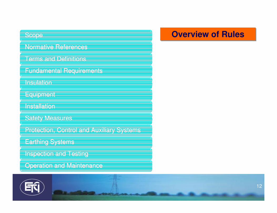
ScopeScope
Normative ReferencesNormative References
Fundamental RequirementsFundamental Requirements
Terms and DefinitionsTerms and Definitions
Safety MeasuresSafety Measures
Earthing SystemsEarthing Systems
Protection, Control and Auxiliary SystemsProtection, Control and Auxiliary Systems
InsulationInsulation
EquipmentEquipment
InstallationInstallation
Inspection and TestingInspection and Testing
Operation and MaintenanceOperation and Maintenance
Overview of RulesOverview of Rules

13
ScopeScope
Normative ReferencesNormative References
Fundamental RequirementsFundamental Requirements
Terms and DefinitionsTerms and Definitions
Safety MeasuresSafety Measures
Earthing SystemsEarthing Systems
Protection, Control and Auxiliary SystemsProtection, Control and Auxiliary Systems
InsulationInsulation
EquipmentEquipment
InstallationInstallation
Inspection and TestingInspection and Testing
Operation and MaintenanceOperation and Maintenance
Overview of RulesOverview of Rules

14
ScopeScope
Normative ReferencesNormative References
Fundamental RequirementsFundamental Requirements
Terms and DefinitionsTerms and Definitions
Safety MeasuresSafety Measures
Earthing SystemsEarthing Systems
Protection, Control and Auxiliary SystemsProtection, Control and Auxiliary Systems
InsulationInsulation
EquipmentEquipment
InstallationInstallation
Inspection and TestingInspection and Testing
Operation and MaintenanceOperation and Maintenance
Overview of RulesOverview of Rules

15
ScopeScope
Normative ReferencesNormative References
Fundamental RequirementsFundamental Requirements
Terms and DefinitionsTerms and Definitions
Safety MeasuresSafety Measures
Earthing SystemsEarthing Systems
Protection, Control and Auxiliary SystemsProtection, Control and Auxiliary Systems
InsulationInsulation
EquipmentEquipment
InstallationInstallation
Inspection and TestingInspection and Testing
Operation and MaintenanceOperation and Maintenance

16
ScopeScope
Normative ReferencesNormative References
Terms and DefinitionsTerms and Definitions
PreliminariesPreliminaries

17
Scope of RulesAspectsAspects
InstallationsInstallationsConnection VoltageConnection VoltageConnection Voltage
Design
Erection
> 1 kV a.c.
50 Hz nominal
Customer Substation
Power Stations (1 site)
Factory, Industrial Agricultural
Commercial or Public Premises

18
Excluded from ScopeLines between installations
Lines between installations
Overhead
Underground
Live working Mining
Test Sites
Ships and Offshore
Factory built switchgear type tested to IEC
Work MethodsWork Methods Equipment and Installations
Equipment and Installations
Electric Railways Electrostatic and Medical
But the rules apply
at the connection
point

19
• A list of all the IEC standards referred to in the document
• E.g. – IEC 60909 determining short circuit currents
– IEC 60617 sets out the symbols to be used on drawings and mimics.
• Incorrect use of symbols may result in a device being used to perform a duty for which it was not intended
2: Normative References2: Normative References

20
Terms and Definitions
• List of definitions of terms used
• Important to avoid confusion in the construction and operation of High Voltage Installations
3: Terms and Definitions3: Terms and Definitions

21
Fundamental RequirementsFundamental Requirements
Safety MeasuresSafety Measures
Earthing SystemsEarthing Systems
Protection, Control and Auxiliary SystemsProtection, Control and Auxiliary Systems
InsulationInsulation
EquipmentEquipment
InstallationInstallation
Design, Equipment and Installation
Design, Equipment and Installation

22
4: Fundamental Requirements4: Fundamental Requirements
Design to take account of:Design to take account of:
Purpose of Installation
User’s Requirements
Safety of operators and public
Environment
Maintenance and Possibility of Extension
23
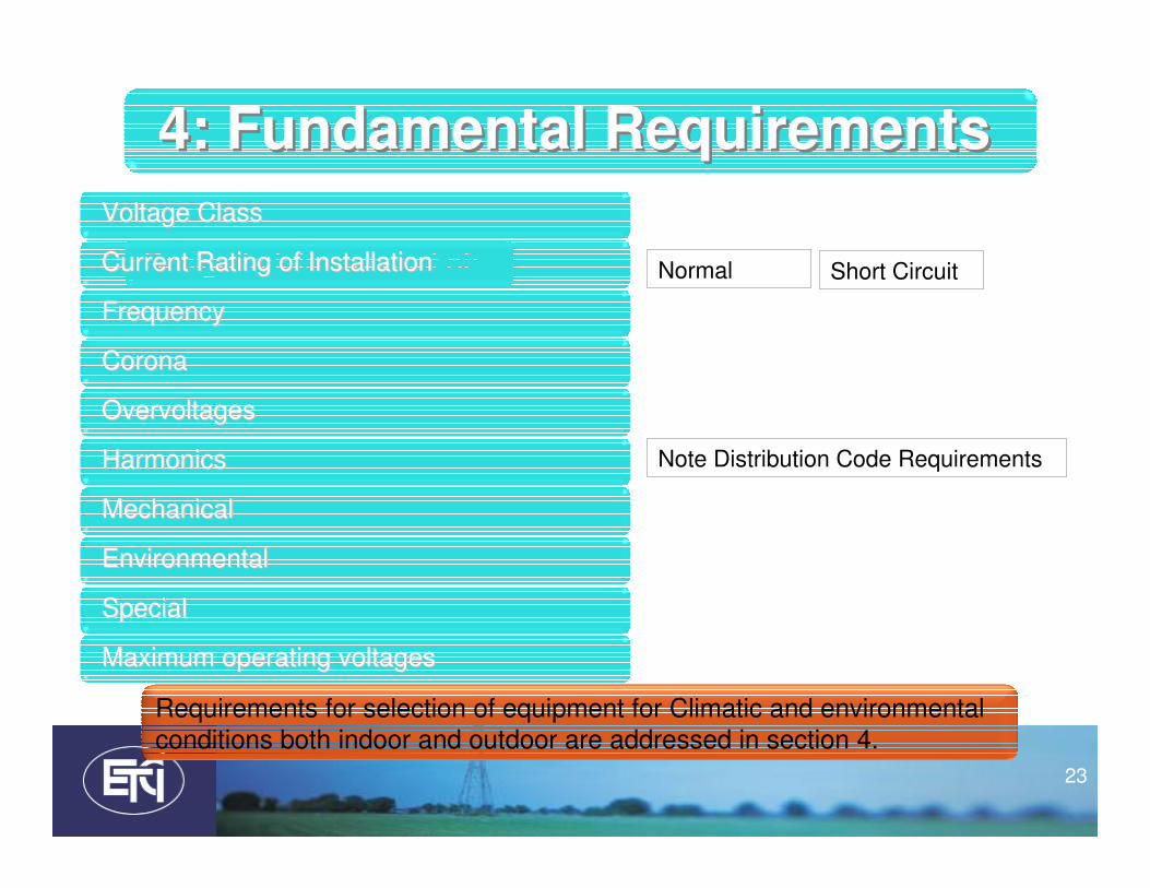
4: Fundamental Requirements4: Fundamental Requirements
Design to take account of:Design to take account of: Normal Short Circuit
Note Distribution Code Requirements
Voltage ClassVoltage Class
Current Rating of InstallationCurrent Rating of Installation
CoronaCorona
FrequencyFrequency
EnvironmentalEnvironmental
Maximum operating voltagesMaximum operating voltages
SpecialSpecial
OvervoltagesOvervoltages
HarmonicsHarmonics
MechanicalMechanical
Requirements for selection of equipment for Climatic and environmental
conditions both indoor and outdoor are addressed in section 4.

24
5: Insulation5: Insulation5: Insulation
Selecting Insulation LevelSelecting Insulation Level
Highest voltage of installation
Impulse withstand voltage
Neutral earthing method
Environment
Basic insulation levels
Clearance distances for 10kV, 20kV and 38kV
Distribution Code RequirementsDistribution Code Requirements

25
Table 1 – Minimum clearances in air – Voltage range I (1 kV < Um ≤ 245 kV)
The Distribution Code requires 125 kV for all these in Ireland
180 mm in Ireland
220 mm in Ireland

26
5: Insulation5: Insulation5: Insulation
Moving to an unearthed 10 kV systemMoving to an unearthed 10 kV system
Earth fault protection
BIL of equipment
Overvoltages in event of arcing earth fault
Phase voltages
In particular on the 10 kV system
Care in equipment selection
Increase in prospective short circuit levelsIncrease in prospective short circuit levels
Change in the Distribution System: Change in the Distribution System: --Implications for existing installationsImplications for existing installations
Insulation and clearances

27
• Selection for:– Safe construction
– Safe operation• Environmental conditions
• Normal operation
• Reasonably expected conditions (overload, fault)
– Protection of personnel during operation and maintenance
• Note installations such as Wind Farms:– Harsh environment
– Remote, loss of supplies
6: Equipment6: Equipment

28
• Instrument transformers:– Protection class
– Measurement class
– Ratio
– Safety Factor
– Accuracy Limit Factor (ALF)
– Burden
• Protection– Sensitive Earth Fault (SEF) protection:
• Directional is recommended
– Directional SEF:• monitoring of the secondary voltage of voltage transformers is crucial
• loss of the residual voltage effectively disables the SEF
• Loss of secondary voltage to directional SEF ideally should initiate other earth fault protection using parameter change over or similar.
6: Equipment6: Equipment

29
• Switchgear
– Indication of position of primary contacts
• Unambiguous
• Clearly visible
– Earth switch locking facilities at the point of
connection to the Distribution System
– Transformers and reactors
• includes protection of the environment if loss of
insulating fluid
6: Equipment6: Equipment

30
• Cables:
– “Code of Practice for avoiding danger from
Underground Services” from HSA
– Installation of single core cables set out
– Installation in unstable ground such as bog
land
• Ground movement may put pressure on cable
terminations, bushings etc.
6: Equipment6: Equipment

31
7: Installations7: Installations
GeneralGeneral
Outdoor installations Outdoor installations –– open designopen design
Prefabricated typePrefabricated type--tested switchgeartested switchgear
Indoor installations Indoor installations –– open designopen design
Requirements for buildingsRequirements for buildings
Prefabricated substationsPrefabricated substations
Installations on Mast, pole and towerInstallations on Mast, pole and tower

32
5: Insulation7: Installations7: Installations
GeneralGeneral
Earth fault protection on each Installation
Locking of isolation equipment
Short circuit withstand
Circuit documentation : each substation
Transport routes
Lighting
Escape and rescue paths
Labelling

33
7: Installations7: Installations
Outdoor installations Outdoor installations –– open designopen design
Clearances
Fences
34
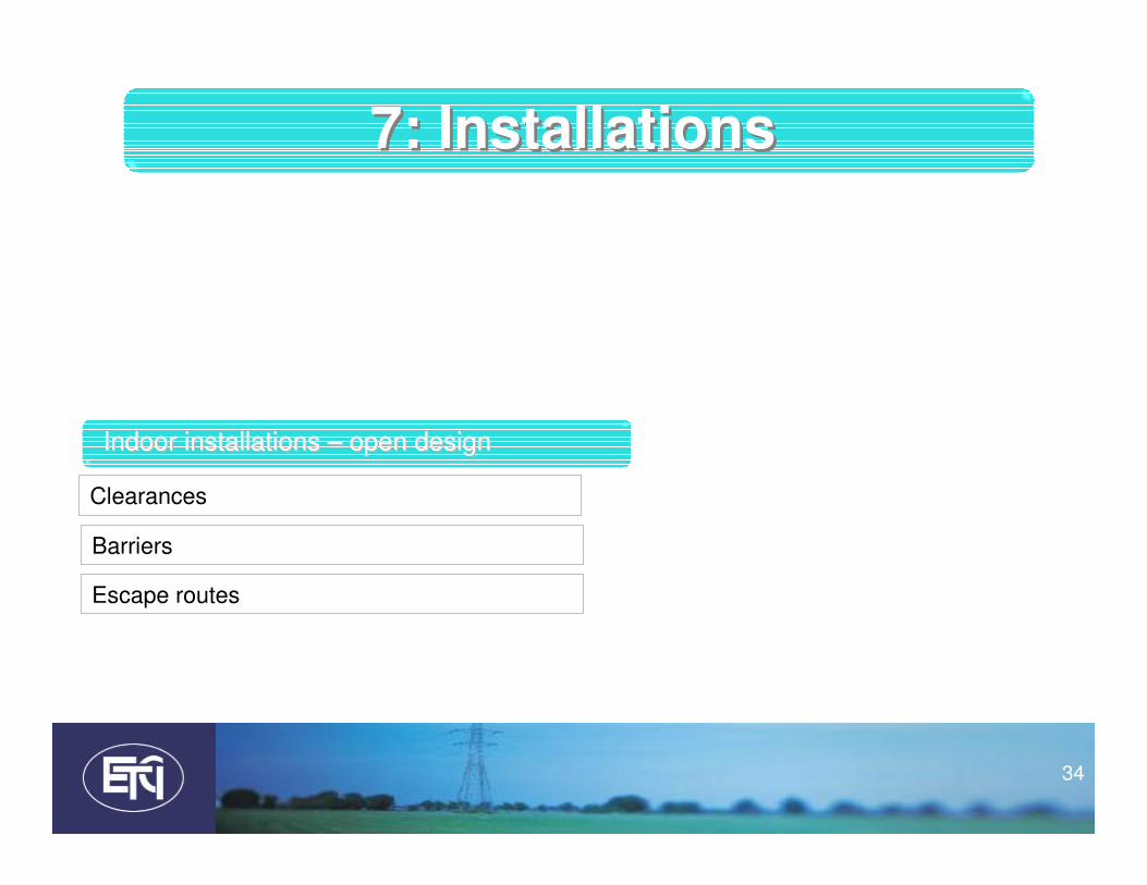
7: Installations7: Installations
Indoor installations Indoor installations –– open designopen design
Clearances
Barriers
Escape routes

35
7: Installations7: Installations
Prefabricated typePrefabricated type--tested switchgeartested switchgear
Additional requirements for SF6

36
7: Installations7: Installations
Requirements for buildingsRequirements for buildings
Ventilation
Structure
Working areas
Battery rooms, emergency generators
Transport routes

37
7: Installations7: Installations
clearancesInstallations on Mast, pole and towerInstallations on Mast, pole and tower

38
• This section covers measures for protection in respect of : – direct contact
– Indirect contact
– Persons working on electrical installations
– Arc fault
– Lightning strokes
– Fire
• Devices to prevent reclosing of isolating devices• Devices for determining the de-energized state• Devices for earthing and short-circuiting• Protection against leakage of insulating liquid and SF6
6: Safety Measures6: Safety Measures
Together with the requirements of IE EN50110 is
the basis for safe operation of HV electrical installations

39
• This section covers:
– Protection, overcurrent, Earth Fault etc.
– DC and AC Supply Circuits
– Compressed Air Systems
– SF6 Gas Handling Plants
– Hydrogen Handling Plants
– EMC of control systems
– Measures to reduce the effects of high and low frequency interference
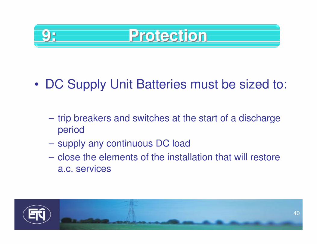
9: Protection9: Protection
40
• DC Supply Unit Batteries must be sized to:
– trip breakers and switches at the start of a discharge
period
– supply any continuous DC load
– close the elements of the installation that will restore a.c. services
9: Protection9: Protection

41
• This section covers:– Design
– Installation
– Testing
– Maintenance
• of earthing systems.
• Main points:– The requirements are designed to address the possibility of a current flowing
through a human being
– based on a probabilistic curve for touch voltage
– In general, interconnection of HV and LV earths is recommended
– The HV earthing system shall form part of the lightning protection system
• This section should be read in conjunction with the Low Voltage National Rules in particular Section 442.
• This section also sets out touch voltage and stress voltage limits arising from Earth Potential Rise (EPR)
10: Earthing10: Earthing

Permissible touch voltage UTp

43
Inspection and TestingInspection and Testing
Operation and MaintenanceOperation and Maintenance
Commissioning and Maintenance
Commissioning and Maintenance
44
• This section covers:– Inspection and tests to verify:
• compliance of the installation with the rules
• Compliance of the equipment with the applicable technical specifications
• Main points– Description of verification by:
• Visual inspection
• Functional tests
• Measuring
– Completion certificate with generator supplement
• These tests must be carried out by a competent person as described in IS EN 5110.
• The following must be available to the person carrying out the inspection– Detailed Drawings and specification for the installation – Fault levels at the point of supply – Details of the supply system earthing (Earthed or Unearthed)– The necessary test equipment to carry out the tests set out in this section.
11: Inspection and Testing11: Inspection and Testing

45
• Note: setting and testing of protection systems:
– the settings issued by SO are the maximum settings
required to discriminate with the public system
– May not:
• adequately protect a consumer’s installation
• satisfy the requirements of these Rules
• Satisfy the requirements of the HSA
– In particular Earth Fault and Short Circuit Settings.
• Also true of synchronising generator protection
settings [check TSO]
11: Inspection and Testing11: Inspection and Testing

46
• Each installation shall have:– An operation manual
• Procedures: Normal, emergency and maintenance
• Safety instructions for operation of HV installation
– A set of up-to-date drawings and diagrams on premises
– Manufacturers’ operation and maintenance manuals
– Visible display of emergency routes to nearest hospital and emergency phone numbers
12: Maintenance Manual12: Maintenance Manual

47
• Site Details– MPRN
– LV Certificate No.
– Customer
– Address
• Connection Ratings– MIC/MEC
– Site Fault Level
– Connection Voltage
– Maximum Curren t
– Minimum Short Circuit Current. This is normally used for Protection Relay settings.
• Supply System Neutral Arrangement. Current legalisation in relation to providing effective earth leakage protection
Completion CertificateCompletion Certificate

48
• Protection Settings and Test Results– Earth Fault
– Sensitive Earth Fault
– Overcurrent
– Generator Y/N
• Equipment Details– Switchgear
– Ring Main Units
– Transformers
– Generators
– Power Factor Correction
– Cable Circuit
– DC Supply Unit
– Generator Protection??
• Verifications– Equipotential Bonding
– Switchgear compliance
– Interlocks Operational
– Facility to lock earth switch
– Operation of DC Units
– Operation of Protection
– Earth Fault Protection
– Transformers
– Cables
– General and Environmental
Completion CertificateCompletion Certificate

49
National Rules for Electrical Installations Exceeding 1 kV ac
Completion Certificate
INSTALLATION
No.
Grid Ref:N . W . Assoc. LV cert. no.
CUSTOMER NAME COMPANY
INSTALLATION ADDRESS
THIS CERTIFICATE IS IN RESPECT OF: CONSTRUCTION & TEST OF INSTALLATION
OR TEST ONLY OF THE EXISTING INSTALLATION
INSTALLATION Date Type Test onl y of exis t. Instal la ti on
CONNECTION RATINGS
MAXIMUM IMPORT CAPACITY kVA kVA
MVA kVA
Connection Max.
Vol tage Mi n. (kA) Max. (kA)
kV A
Supply System Neutral Arrangement: via i nductor
TEST RESULTS
Resistance of Earthing System Resistance of Earth System Compliant? (Y/N)
PROTECTION SETTINGS AND TESTSProtection at Main Incomer (Connection Point)
Earth Fault relay manufacturer type
settings I0> A s
I0>> A s
L2 L3
injection test I0> A s s s
I0>> A s s s
Sensitive relay manufacturer type
Earth Faultsettings I0> A s
injection test I0> A s
Overcurrent relay manufacturer type
settings I> A s
I>> A s
L2 L3
injection test I> A s s s
I>> A s s s
Generator If 'Y', complete Embedded Generator Interface Protection (EGIP) form
13 phase fault current
2Line to Earth Fault Current
Building
Street
City/Town
County
SITE FAULT LEVEL
Synchronising Generator (Y/N)
ohms
MAXIMUM EXPORT CAPACITY
tri pping curve
via res i s tor
ti me
MPRN
Current
partia la lterationnew
TOTAL SITE GENERATION CAPACITY
tri pping curve
unearthedsol id
I”k31
I”k12
L1
L1
tri pping curve
tri pping curve
tri pping curve
ti me
ti me
Site Details
Connection
Ratings
Settings and
Test Results
Sensitive
Earth Fault
Overcurrent
Earth Fault

50
Equipment
Details
Verifications
Certification
EQUIPMENT DETAILS
Quantity Type Ratings (as a ppl icable)
m
Switchgear
Ring Main Units
Transformers
Generators
Power Factor Correction
Cable Circuit
DC Supply Unit
Generator Protection
VERIFICATIONSMain Substation Other Substations
(tick as appropriate)Equipotential Bonding
Switchgear Compliant?
Are Interlocks Operational
Facility to Lock Earth Switch
Operation of DC Units
Operation of Protection
Overcurrent Protection at main switchboard
Earth Fault Protection at main switchboard
Transformers
Cables
General and Environmental
COMMENT OR DETAILS CONTRACTORReg. no. Reg. Body
NameAddress
Tel:
CERTIFICATIONPre-connection tests completed and found to be satisfactory
For installation (tick as appropriate)Signed Constructor
Qualification
NOTE:This certificate is issued and signed by the person responsible for the constructing and/or testing of the installation or a person duly authorised
to act on his behalf. This certificate should be used only for installations connected at voltages over 1 kV ac. Installations connected at a lower
voltage require a different certificate. Electrical Installations should be inspected periodically.
The Electro-Technical Council is not responsible for the electrical installation or for the accuracy of the information given on this certificate.
© ETCI 2011 This document must not be reproduced in any form or manner without the express permission of the Electro-Technical Council of Ireland
nos.
LengthBIL
Test
Sheet
kVA kVAr
Tester
kVkAVDCkV A
Yes
at all sub switchboards
Mob.
Yes
at all sub switchboards

51
National Rules for Electrical Installations Exceeding 1 kV ac
Completion Certificate
INSTALLATION
No.
Grid Ref:N . W . Assoc. LV cert. no.
CUSTOMER NAME COMPANY
INSTALLATION ADDRESS
THIS CERTIFICATE IS IN RESPECT OF: CONSTRUCTION & TEST OF INSTALLATION
OR TEST ONLY OF THE EXISTING INSTALLATION
INSTALLATION Date Type Test only of exis t. Insta l lation
CONNECTION RATINGS
MAXIMUM IMPORT CAPACITY kVA kVA
MVA kVA
Connection Max.
Vol tage Min. (kA) Max. (kA)
kV A
Supply System Neutral Arrangement: via inductor s ol id
I”k31
I”k12
SITE FAULT LEVEL
MAXIMUM EXPORT CAPACITY
via res is tor
MPRN
Current
partia la l terationnew
TOTAL SITE GENERATION CAPACITY
unearthed
Building
Street
City/Town
County

52
TEST RESULTS
Resistance of Earthing System Resistance of Earth System Compliant? (Y/N)
PROTECTION SETTINGS AND TESTSProtection at Main Incomer (Connection Point)
Earth Fault relay manufacturer type
settings I0> A s
I0>> A s
L2 L3
injection test I0> A s s s
I0>> A s s s
Sensitive relay manufacturer type
Earth Faultsettings I0> A s
injection test I0> A s
Overcurrent relay manufacturer type
settings I> A s
I>> A s
L2 L3
injection test I> A s s s
I>> A s s s
Generator If 'Y', complete Embedded Generator Interface Protection (EGIP) form
13 phas e faul t current
2Line to Earth Faul t Current
Synchronising Generator (Y/N)
ohms
tripping curve
time
tripping curve
L1
L1
tripping curve
tripping curve
tripping curve
time
time

53
EQUIPMENT DETAILS
Quantity Type Ratings (as appl i cable)
m
Switchgear
Ring Main Units
Transformers
Generators
Power Factor Correction
Cable Circuit
DC Supply Unit
Generator Protection
VERIFICATIONSMain Substation Other Substations
(tick as appropriate)Equipotential Bonding
Switchgear Compliant?
Are Interlocks Operational
Facility to Lock Earth Switch
Operation of DC Units
Operation of Protection
Overcurrent Protection at main switchboard
Earth Fault Protection at main switchboard
Transformers
Cables
General and Environmental
nos.
LengthBIL
Test
Sheet
kVA kVAr kVkAVDCkV A
Yes
at all sub switchboards
Yes
at all sub switchboards

54
MPRN &
Certificate
no.
Directional
Overcurrent
Over/ Under
Frequency
National Rules for Electrical Installations Exceeding 1 kV ac
Completion Certificate
Part B. Synchronising Generator Installation
Note: This supplementary sheet forms part of the Completion Certificate above
GENERATOR PROTECTION SETTINGS AND TESTS Current 5 Volt.
Directional type
Overcurrent setting I> A s tri ppi ng curve rela y cha racteristi c a ngl e °
L1 L2 L3
timing test injected current, phase a ngl e I> A Ø ° I> A Ø ° I> A Ø °
trip time s s s
directiona l injected current, tri p ph. a ngle I> A Ø ° I> A I> A
test reset phas e a ngle Ø ° Ø ° Ø °
s s s
Over/Under type
Voltage
Over volta ge setting V> V s
L1 L2
timing test injected vol tage V V V
trip time s s s
set point test trip volta ge V V V
res et vol tage V V V
Under voltage setting V< V s
timing test injected vol tage V V V
trip time s s s
set point test trip volta ge V V V
res et vol tage V V V
Over/Under type
Frequency
Over frequency s etting f> Hz s
timing test injected frequency f> Hz s
set point test f> Hz Hz
Under frequency setti ng f< Hz s
timing test injected frequency f< Hz s
set point test trip frequency Hz HzHz
Earth Fault type
(NVD) settings V s
timing test s s
set point test trip volta ge V reset volta ge V
Loss of Mains type
1. Vector Shift settings Ø ° s
min. vol t. Vector shi ft to trip Ø ° ma x. s hi ft, no trip Ø °
2. Rate of Changesettings Hz/s s
of frequency timing test Hz/s s
(ROCOF) set point test Hz/s ROCOF reset Hz/s
Trip Circuit Supervision correct operation of trip cicuit supervis ion
Site Safety Warning notices in pla ce advis i ng of generator(s ) in pa ral lel opera tion
Generator tests completed and found to be satisfactorySigned
© ETCI 2011 This document must not be reproduced in any form or manner without the express permission of the Electro-This document must not be reproduced in any form or manner without the express permission of the Electro-Technical Council of Ireland
Completion Certificate No.
tripping curve
tripping curve
MPRN
ROCOF Trip
tripping curve
tripping curve
timei nj. rate of change of frequency
i njected voltage
100PROT. TRANSFORMER RATIOS
trip ti me
rela y manufa cturer
tripping curve
trip frequency
rela y manufa cturer
rel ay ma nufacturer
rel ay ma nufacturer
rel ay ma nufacturer
time
time
L3
time
time
time
ti me
time
reset frequency
reset frequency
Over/under
Voltage
Earth Fault
Loss of
Mains
Rate of
Change of
Freq.

55
National Rules for Electrical Installations Exceeding 1 kV ac
Completion Certificate
Part B. Synchronising Generator Installation
Note: This supplementary sheet forms part of the Completion Certificate above
GENERATOR PROTECTION SETTINGS AND TESTS Current 5 Volt.
Directional type
Overcurrent setting I> A s tripping curve relay characteris tic angle °
L1 L2 L3
timing test injected current, phas e angle I> A Ø ° I> A Ø ° I> A Ø °
trip time s s s
directional injected current, trip ph. angle I> A Ø ° I> A I> A
test res et phase angle Ø ° Ø ° Ø °
s s s
Over/Under type
Voltage
Over voltage setting V> V s
L1 L2
timing test injected voltage V V V
trip time s s s
set point test trip voltage V V V
reset vol tage V V V
Under vol tage setting V< V s
timing test injected voltage V V V
trip time s s s
set point test trip voltage V V V
reset vol tage V V V
Completion Certificate No.
tripping curve
tripping curve
MPRN
100PROT. TRANSFORMER RATIOS
relay manufacturer
relay manufacturer
L3
time
time

56
Over/Under type
Frequency
Over frequency setting f> Hz s
timing test injected frequency f> Hz s
set point test f> Hz Hz
Under frequency setting f< Hz s
timing test injected frequency f< Hz s
set point test trip frequency Hz HzHz
Earth Fault type
(NVD) settings V s
timing test s s
set point test trip voltage V reset vol tage V
Loss of Mains type
1. Vector Shift settings Ø ° s
min. vol t. Vector shi ft to trip Ø ° max. shi ft, no trip Ø °
2. Rate of Changesettings Hz/s s
of frequency timing test Hz/s s
(ROCOF) set point tes t Hz/s ROCOF reset Hz/s
Trip Circuit Supervision correct operation of trip cicuit supervis ion
Site Safety Warning notices in place advis ing of generator(s ) in para l lel operation
Generator tests completed and found to be satisfactorySigned
© ETCI 2011 This document must not be reproduced in any form or manner without the express permission of the Electro-This document must not be reproduced in any form or manner without the express permission of the Electro-Technical Council of Ireland
ROCOF Trip
tripping curve
tripping curve
timeinj. rate of change of frequency
injected vol tage
trip time
relay manufacturer
tripping curve
trip frequency
relay manufacturer
relay manufacturer
time
time
time
time
time
reset frequency
reset frequency

57
Next Steps
• Consultation
• Amendments
• Publication
• Arrangements
• Briefing and Communication
• Maintenance


59
Questions

Thank You

61
Ireland must speed up the permitting process for investment in essential infrastructure


