338 ‘New Austrian Tunnelling Method’. ‘Sequential Excavation Method’. ‘Sprayed Concrete Lining’. Not even the tunnelling industry can give a unified name for a tunnelling method pioneered by the Austrians in the later half of the twentieth century. Furthermore, we are seeing increased use of this method in the US, particularly in soft-ground conditions. In order to better define the method, it is helpful to look at its history and use in both design and construction. NATM in perspective As defined by the Austrian Society ofEngineers and Architects, the NATM “…constitutes a method where the surrounding rock or soil formations of a tunnel are integrated into an overall ring- like support structure. Thus the supporting formations will themselves be part of this supporting structure.” In world-wide prac- tice, however, when shotcrete is proposed for initial ground support of an open-face tunnel, it is often referred to as NATM. The term NATM with reference to soft ground, however, can be misleading. As noted in a very thoughtful article by Emit Brown 1 , NATM can refer to both a design philo soph y and a construction method. Key features of the NATM design philosophy are: The strength of the ground around a tunnel is deliberately mobilised to the maximum extent possible. Mobilisation of ground strength is achieved by allowing controlled defor- mation of the ground. Initial primary support is installed having load-deformation characteristics appro- priate to the ground conditions, and installation is timed with respect to ground deformations. Instrumentation is installed to monitor deformations in the initial support system, as well as to form the basis ofvarying the initial support design and the sequence of excavation. Key features of NATM construction methods are: The tunnel is sequentially excavated and supported, and the excavation sequences can be varied. The initial ground support is provided by shotcrete in combination with fibre or welded-wire fabric reinforcement, steel arches (usually lattice girders), and sometimes ground reinforcement (e.g., soil nails, spiling). The permanent support is usually (but not always) a cast-in-place concrete lining. It should be noted that many of the construction methods described above were in widespread use in the US and elsewhere in soft-ground applications before NATM was described in the litera- ture. In current practice, for soft-ground tunnels which are referred to as NATM tunnels, initial ground support in the form of shotcrete (usually with lattice girders and some form of ground reinforcement) is installed as excavation proceeds, followed by installation of a final lining at a later date. Simply speaking, soft ground can be described as any type of ground requiring support as soon as possible after excava- tion in order to maintain stability of the NATM & SH OTCRETING FOCUS NATM IN SOFT-GROUND: A CONTRADICTION OF TER MS?W hen the New Austrian Tunnelling Method (NATM) is mentioned, it often means many different things to even experienced tunnelling engineers. The scene has more recently been complicated by new terms introduced to reflect certain aspects of NATM. Victor Romero, an associate with US-based engineering practice Jacobs Associates gives his views on NATM and its application to soft-ground tunnelling, and dispels some misconceptions about this sometimes controversial topic. Generic ground reaction curve that is often the basis of NATM design (after Brown, 1981 1 ) NATM in soft-ground 3/9/02 03:44 pm Page 338
‘New Austrian Tunnelling Method’.‘Sequential Excavation Method’. ‘SprayedConcrete Lining’. Not even the tunnellingindustry can give a unified name for atunnelling method pioneered by the
Austrians in the later half of the twentiethcentury. Furthermore, we are seeingincreased use of this method in the US,particularly in soft-ground conditions. Inorder to better define the method, it ishelpful to look at its history and use in bothdesign and construction.
NATM in perspectiveAs defined by the Austrian Society of Engineers and Architects, the NATM“…constitutes a method where thesurrounding rock or soil formations of atunnel are integrated into an overall ring-like support structure. Thus the supporting
formations will themselves be part of thissupporting structure.” In world-wide prac-tice, however, when shotcrete is proposedfor initial ground support of an open-facetunnel, it is often referred to as NATM. Theterm NATM with reference to soft ground,however, can be misleading.
As noted in a very thoughtful article by EmitBrown1, NATM can refer to both a design philosophy and a construction method . Keyfeatures of the NATM design philosophy are:
The strength of the ground around atunnel is deliberately mobilised to themaximum extent possible.
Mobilisation of ground strength isachieved by allowing controlled defor-mation of the ground.
Initial primary support is installed havingload-deformation characteristics appro-priate to the ground conditions, andinstallation is timed with respect toground deformations.
Instrumentation is installed to monitordeformations in the initial supportsystem, as well as to form the basis of varying the initial support design and thesequence of excavation.
Key features of NATM constructionmethods are:
The tunnel is sequentially excavated andsupported, and the excavation sequencescan be varied.
The initial ground support is provided byshotcrete in combination with fibre orwelded-wire fabric reinforcement, steelarches (usually lattice girders), andsometimes ground reinforcement (e.g.,soil nails, spiling).
The permanent support is usually (butnot always) a cast-in-place concrete lining.
It should be noted that many of theconstruction methods described above
were in widespread use in the US andelsewhere in soft-ground applicationsbefore NATM was described in the litera-ture. In current practice, for soft-groundtunnels which are referred to as NATMtunnels, initial ground support in the formof shotcrete (usually with lattice girders andsome form of ground reinforcement) isinstalled as excavation proceeds, followedby installation of a final lining at a later date.
Simply speaking, soft ground can bedescribed as any type of ground requiringsupport as soon as possible after excava-tion in order to maintain stability of the
NATM & SH OTCRETING FOCUS
NATM IN SOFT-GROUND:
A CONTRADICTION OF TERMS?
When the New Austrian Tunnelling Method (NATM) is mentioned, it often means many differentthings to even experienced tunnelling engineers. The scene has more recently been complicatedby new terms introduced to reflect certain aspects of NATM. Victor Romero, an associate withUS-based engineering practice Jacobs Associates gives his views on NATM and its application to
soft-ground tunnelling, and dispels some misconceptions about this sometimes controversial topic.
Generic ground reaction curve that is often the basis of NATM design (after Brown, 19811 )
excavation. For tunnels in dense urbanareas, limiting settlement is of paramountimportance to avoid damage to overlyingstructures. In order to limit settlement
and ensure worker safety, most softground tunnels employ the followingmeasures:
Excavation stages must be sufficientlyshort, both in terms of dimensions andduration.
Erection of the ‘full ring’ of initial groundsupport must be completed immedi-ately after excavation.
It should be noted that the major differ-ence between the NATM design philos-ophy and traditional soft ground tunnelconstruction measures is that deformation
of the soil is not easily ‘controlled’.Therefore, it can be concluded that theexcavation and support planned forsequentially excavated, shotcrete-linedtunnels in soft ground utilises NATMconstruction methods but not necessarilyNATM design methods.
NATM for soft ground? In soft-ground tunnelling, safety dictatesthat the ground support be placed immedi-ately after excavation. As long as theground is properly supported, NATMconstruction methods are appropriate forsoft-ground conditions. However, there arecases where soft-ground conditions do notfavour an open face with a short length of uncompleted lining immediately next to it,such as in flowing ground or ground withshort stand-up time (i.e., failure to developa ground arch). Unless such unstableconditions can be modified by dewatering,spiling, grouting, or other methods of ground improvement, then NATM may beinappropriate. In these cases, close-faceshield tunnelling methods may be moreappropriate for safe tunnel construction.
A ‘black box’ for design? Is a computerized ‘black box’ appropriatefor NATM design? By ‘black box’ I mean a
numerical model that presumes tocalculate stresses in the ground and tunnelsupport (i.e. lining). Traditionally, this hasbeen done with finite element or finite
difference methods. As with any computermodelling, the answers are only as good asthe geotechnical input parameters and theconstituent models used for analysis. Theconstituent model theories should not be amystery, and both the Engineer and theClient (be it an owner or a contractor)should clearly understand the limitations of computer modelling. Most importantly, fieldobservations and measurements should be
SOFT GROUND NATM
339
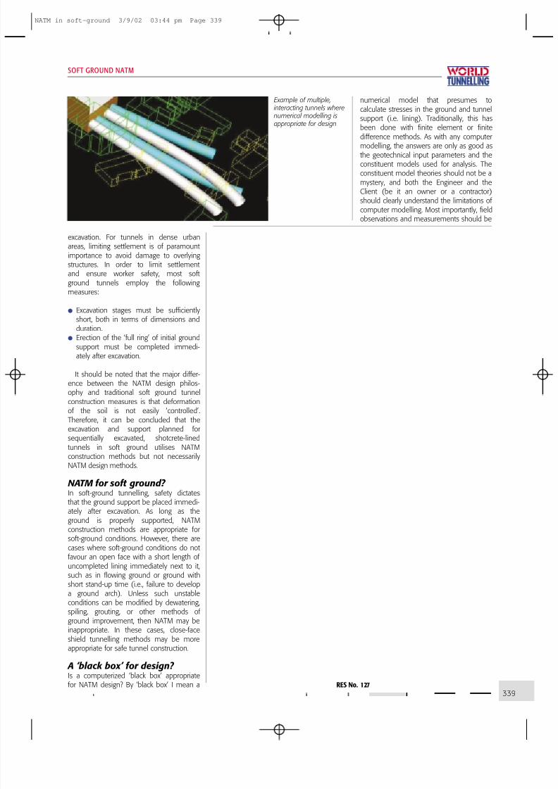
Example of multiple, interacting tunnels where numerical modelling isappropriate for design
used to confirm assumptions and calibratefuture models.
Notwithstanding the above, numericalmodelling is a useful tool for design of
sequentially excavated, shotcrete-linedtunnels in soft ground. In particular, numer-ical modelling is useful where interactingtunnels, unusual geometries, or adjacentstructures are present. We prefer to use thesoftware FLAC or PLAXIS for numericalmodelling of tunnel linings in soft-ground.However, if a shotcrete-lined tunnel has asection that is nearly circular or oval withno irregularities, and if there are no adja-cent surface or subsurface structure inter-acting with the tunnel, then traditionalground-lining interaction methods can beused for design. Indeed, the closed-formground-lining interaction equations provide
a prudent check on numerical modelling.So do you need a black box? If you don’tknow what the theory behind the black boxis and cannot correlate the analysis withtunnel behaviour in the field, then youshould not rely on a black box for any type of tunnel design. However, if you areusing a tested program with goodconstituent models and know its limita-tions, then programs such as FLAC canbe useful design tools. But be sure toverify the results in the field and with atraditional ground-lining interaction analysis,if appropriate.
Instrumentation and monitoring? As noted above, instrumentation and moni-toring play a key role in verifying designassumptions and calibrating numerical
models. More importantly, however, moni-toring serves to alert the designer and theconstructor if the lining is not performing asintended, or is in danger of collapse. In thisrespect instrumentation of NATM construc-tion is no different from other types of geotechnical construction. Therefore thetried and true rules of thumb for geotech-nical instrumentation apply to NATM,
namely:
1. Predict mechanisms that control behav-iour, and define the geotechnical ques-tions to be answered.
2. Define the purpose of instrumentation,and select parameters to be monitored.
3. Predict magnitudes of change, anddetermine threshold limits and remedialactions.
4. Assign tasks and responsibilities.5. Select instruments and locations.6. Devise methods to ensure correctness.7. Plan data collection, processing, presen-
tation, interpretation, and reporting.
If you get these steps in a systematicinstrumentation and monitoring approachcorrect, and there is good communicationbetween the Engineer and the Contractor,then you have a fighting chance ofgetting good data that can be relied upon,in order to make decisions duringconstruction.
Tunnel collapses? Unfortunately there have been severalcollapses or other stability failures of NATMprojects around the world including, mostrecently in Turkey and the US. Perhaps themost famous is the Heathrow Airportcollapse in October 1994, which triggereda thorough review of the NATM by theBritish Health and Safety Executive (HSE).In a 1996 report2, the HSE examined 39NATM failures, categorising the location (inthe tunnel) of the failure. In most cases,the failure was a result of heading collapse.Broadly speaking the causes of these fail-ures were varied, from unanticipatedgeologic conditions, to design errors, toconstruction quality problems, to poormanagement. Nevertheless NATM failures,or for that matter any tunnel failure, haveone thing in common: most are caused
SOFT GROUND NATM
340
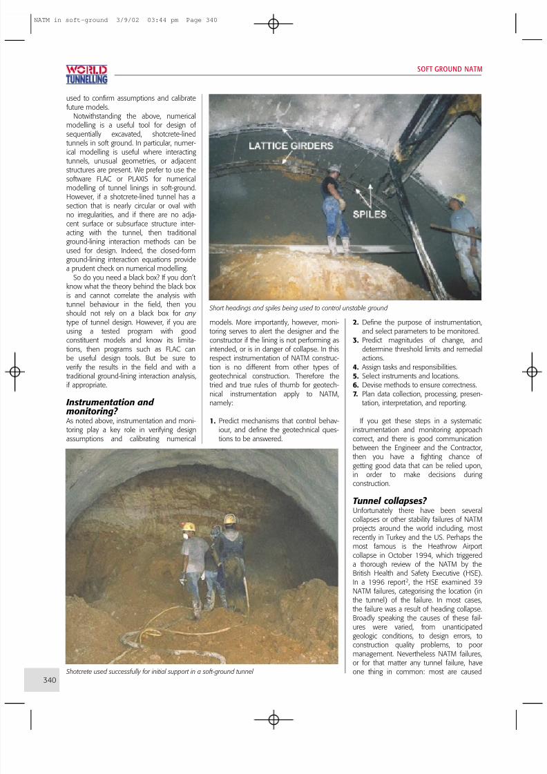
Short headings and spiles being used to control unstable ground
Shotcrete used successfully for initial support in a soft-ground tunnel
by human error. It’s not the fault ofthe method, but misapplication of themethod.
What do we call it?On the question of terminology, it is diffi-cult to cover all aspects of the method. TheBritish have proposed SCL, short forSprayed Concrete Linings (Institution of Civil Engineers, 19963). However, the term‘sprayed concrete’ is not very common inthe US and many other parts of the world,where shotcrete is the commonly usedterm for pneumatically applied concrete.Moreover, shotcrete is used in differenttypes of tunnels (rock and soft ground)and for many different applications (aslining, lagging, surface protection, etc.).Since the use of shotcrete lining in soft-
ground tunnels is almost always associatedwith sequential excavation, my preferredterminology is SEM, for SequentialExcavation Method. The use of SEM asstandard tunnel terminology also highlightsthe fact that this is a construction method,rather than a design method. I would,however, recommend keeping NATM asterminology for the design method used inrock tunnels when support installation istimed to a ground reaction curve.
References1 Brown, E.T. Putting the NATM into
perspective. Tunnels & Tunnelling,
November 1981.2 Health & Safety Executive. Safety ofNew Austrian Tunnelling Method
(NATM) Tunnels, A review of sprayedconcrete lined tunnels with particularreference to London Clay, HSE Books1996.
3
Institution of Civil Engineers. Sprayedconcrete linings (NATM) for tunnels insoft ground. ICE design and practiceguide, Thomas Telford Publishers,London, UK 1996.
Acknowledgement Most of this article was first published inFinal Liner , the Jacobs Associates news- letter, Spring 2002.
If you, the readers, have views on theterminology most appropriate to ‘NATM’ sequential excavation, shotcrete liningsor observational methods please share
them with other readers in the formof a Letter to the Editor of WorldTunnelling , or submitted articles for longer arguments or examples of method deployment.
Victor Romero Associate – Jacobs Associates
SOFT GROUND NATM
343
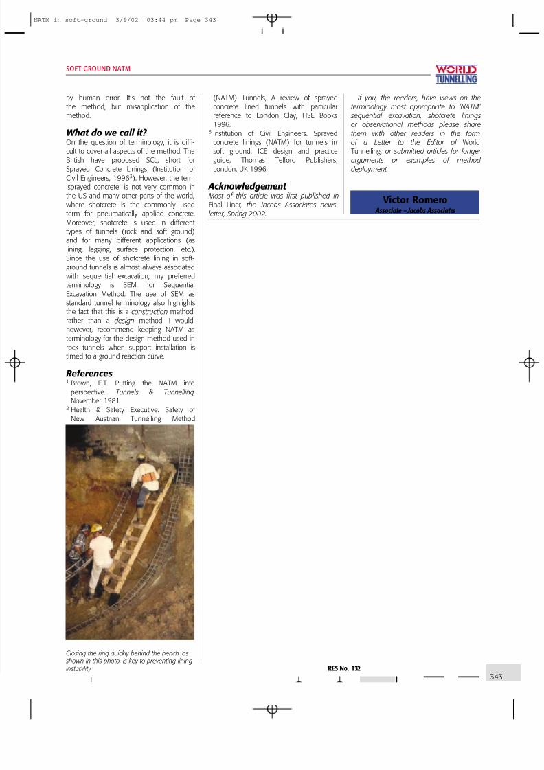
Closing the ring quickly behind the bench, as shown in this photo, is key to preventing lining instability RES No. 132